CN100464899C - An aluminum alloy vacuum pouring device - Google Patents
An aluminum alloy vacuum pouring device Download PDFInfo
- Publication number
- CN100464899C CN100464899C CNB2007100149961A CN200710014996A CN100464899C CN 100464899 C CN100464899 C CN 100464899C CN B2007100149961 A CNB2007100149961 A CN B2007100149961A CN 200710014996 A CN200710014996 A CN 200710014996A CN 100464899 C CN100464899 C CN 100464899C
- Authority
- CN
- China
- Prior art keywords
- cylinder
- connecting rod
- autoclave
- pouring
- tank
- Prior art date
- Legal status (The legal status is an assumption and is not a legal conclusion. Google has not performed a legal analysis and makes no representation as to the accuracy of the status listed.)
- Expired - Fee Related
Links
- 229910000838 Al alloy Inorganic materials 0.000 title claims abstract description 13
- 238000005266 casting Methods 0.000 claims description 14
- 238000000034 method Methods 0.000 abstract description 5
- 244000035744 Hura crepitans Species 0.000 description 5
- XAGFODPZIPBFFR-UHFFFAOYSA-N aluminium Chemical compound [Al] XAGFODPZIPBFFR-UHFFFAOYSA-N 0.000 description 3
- 229910052782 aluminium Inorganic materials 0.000 description 3
- 238000004519 manufacturing process Methods 0.000 description 3
- 239000004576 sand Substances 0.000 description 3
- 239000002893 slag Substances 0.000 description 3
- XLYOFNOQVPJJNP-UHFFFAOYSA-N water Substances O XLYOFNOQVPJJNP-UHFFFAOYSA-N 0.000 description 3
- 230000007547 defect Effects 0.000 description 2
- 238000012797 qualification Methods 0.000 description 2
- 229910000861 Mg alloy Inorganic materials 0.000 description 1
- AZDRQVAHHNSJOQ-UHFFFAOYSA-N alumane Chemical group [AlH3] AZDRQVAHHNSJOQ-UHFFFAOYSA-N 0.000 description 1
- SNAAJJQQZSMGQD-UHFFFAOYSA-N aluminum magnesium Chemical compound [Mg].[Al] SNAAJJQQZSMGQD-UHFFFAOYSA-N 0.000 description 1
- 238000010586 diagram Methods 0.000 description 1
- 238000010438 heat treatment Methods 0.000 description 1
- 239000007788 liquid Substances 0.000 description 1
- 238000007711 solidification Methods 0.000 description 1
- 230000008023 solidification Effects 0.000 description 1
Images
Classifications
-
- B—PERFORMING OPERATIONS; TRANSPORTING
- B22—CASTING; POWDER METALLURGY
- B22D—CASTING OF METALS; CASTING OF OTHER SUBSTANCES BY THE SAME PROCESSES OR DEVICES
- B22D27/00—Treating the metal in the mould while it is molten or ductile ; Pressure or vacuum casting
- B22D27/15—Treating the metal in the mould while it is molten or ductile ; Pressure or vacuum casting by using vacuum
Landscapes
- Engineering & Computer Science (AREA)
- Mechanical Engineering (AREA)
- Manufacture And Refinement Of Metals (AREA)
Abstract
本发明公开了一种铝合金真空浇注装置,包括高压釜罐,高压釜罐内安装导轨,高压釜罐与压缩空气管路一端连接,压缩空气管路另一端与增压罐连接,高压釜罐上部开设第一浇注窗口和第二浇注窗口,第一浇注窗口和第二浇注窗口一侧安装第一气缸,第一气缸的活塞杆与第一连杆连接,第一连杆与浇注窗口盖连接,高压釜罐底部安装固定导轨和活动导轨,高压釜罐一端安装活动门,门连杆一端与高压釜罐连接,活动门与第三气缸连接,高压釜罐一侧安装排气电动球阀。本发明的优点是:除漏斗的放入和取出外将所有工序均采用自动化操作完成,实现了真空状态下的浇注,大幅度降低了劳动强度,为本领域浇注大型薄壁工件,提供了一种安全可靠的设备。
The invention discloses an aluminum alloy vacuum pouring device, which comprises an autoclave tank, a guide rail is installed in the autoclave tank, one end of the autoclave tank is connected with a compressed air pipeline, the other end of the compressed air pipeline is connected with a pressurized tank, and the autoclave tank is connected with a pressurized tank. The first pouring window and the second pouring window are set on the upper part, the first cylinder is installed on the side of the first pouring window and the second pouring window, the piston rod of the first cylinder is connected with the first connecting rod, and the first connecting rod is connected with the pouring window cover , The bottom of the autoclave tank is equipped with fixed guide rails and movable guide rails, one end of the autoclave tank is equipped with a movable door, one end of the door connecting rod is connected to the autoclave tank, the movable door is connected to the third cylinder, and an exhaust electric ball valve is installed on one side of the autoclave tank. The invention has the advantages that all processes are completed by automatic operation except for the putting in and taking out of the funnel, the pouring under vacuum is realized, the labor intensity is greatly reduced, and a large-scale thin-walled workpiece is poured in this field. A safe and reliable device.
Description
技术领域 technical field
本发明涉及铝合金生产设备,是一种在真空状态下实现浇注的一种铝合金真空浇注装置。The invention relates to aluminum alloy production equipment, which is an aluminum alloy vacuum pouring device which realizes pouring in a vacuum state.
背景技术 Background technique
铝合金工件的浇注许多是在罐体内完成的。目前采用高压釜罐体浇注工件是将砂箱吊装到台车上后,人工将高压釜罐体内部活动导轨放倒,然后人工将门打开,再将罐内的活动导轨竖起,最后人工将砂箱台车推入罐体内并定位。在接下来的浇注就位、浇注、增压与凝固、排气和砂箱移出,所有工序均采用人工手动操作完成。这种装置的不足是:由于各结构的设置欠合理性,必须采用人工手动操作完成,劳动强度大,存在不安全因素较多,铸件的废品率高,特别是浇注大型薄件时,铸件上的针孔及二次夹渣等问题始终较难解决,使大型薄件的产品合格率仅为30%左右。因此,如何解决浇注工件避免出现针孔及二次夹渣等问题,提高铝合金工件的浇注质量,是本领域一直研究的主要课题之一,从目前报道的各种方法和装置中也未得到任何启示。Most of the pouring of aluminum alloy workpieces is done in the tank. At present, the casting of workpieces in autoclave tanks is to lift the sand box onto the trolley, manually lay down the movable guide rails inside the autoclave tank, then manually open the door, then erect the movable guide rails in the tank, and finally manually place the sand The trolley is pushed into the tank and positioned. In the following pouring in place, pouring, pressurization and solidification, exhaust and removal of the sand box, all processes are completed manually. The disadvantages of this device are: due to the unreasonable setting of each structure, it must be completed manually, the labor intensity is high, there are many unsafe factors, and the rejection rate of castings is high, especially when pouring large thin parts, the castings on the Problems such as pinholes and secondary slag inclusions are always difficult to solve, so that the product qualification rate of large thin parts is only about 30%. Therefore, how to solve the problems such as pinholes and secondary slag inclusions in pouring workpieces and improve the pouring quality of aluminum alloy workpieces is one of the main subjects of research in this field, and has not been obtained from the various methods and devices reported so far. any enlightenment.
发明内容 Contents of the invention
本发明的目的是,提供一种铝合金真空浇注装置,它全部采用分步自动化操作,以期降低操作者的劳动强度,消除不安全因素,降低产品废品率。The object of the present invention is to provide an aluminum alloy vacuum pouring device, all of which adopt step-by-step automatic operation, in order to reduce the labor intensity of the operator, eliminate unsafe factors, and reduce the product rejection rate.
本发明为实现上述目的,通过以下技术方案实现:一种铝合金真空浇注装置,包括高压釜罐,高压釜罐内安装导轨,高压釜罐与压缩空气管路一端连接,压缩空气管路另一端与增压罐连接,压缩空气管路上安装进气电动球阀,高压釜罐上部开设第一浇注窗口和第二浇注窗口,第一浇注窗口和第二浇注窗口一侧安装第一气缸,第一气缸的活塞杆与第一连杆连接,第一连杆与第一浇注窗口盖连接,高压釜罐内底部安装固定导轨和活动导轨,第一活动导轨与第四气缸连接,第二活动导轨与第五气缸连接,高压釜罐一端安装活动门,活动门与门连杆连接,门连杆一端与高压釜罐连接,活动门与第三气缸连接,高压釜罐一侧安装排气电动球阀。高压釜罐上部内侧安装第一挡板和第二挡板,第一挡板通过连接件与第一连杆连接,第二挡板通过连接件与第二连杆连接。活动导轨为两条,第一活动导轨下部与第一转轴连接,第一转轴通过连杆与第四气缸连接,第二活动导轨下部与第二转轴连接,第二转轴通过连杆与第五气缸连接。高压釜罐内壁上设置支撑筋。高压釜罐外壁上安装真空压力表、手动排气管和自动排气管。In order to achieve the above object, the present invention is achieved through the following technical solutions: an aluminum alloy vacuum pouring device, including an autoclave tank, a guide rail is installed in the autoclave tank, one end of the autoclave tank is connected with a compressed air pipeline, and the other end of the compressed air pipeline is It is connected with the pressurized tank, the air intake electric ball valve is installed on the compressed air pipeline, the first pouring window and the second pouring window are set on the upper part of the autoclave tank, the first cylinder is installed on the side of the first pouring window and the second pouring window, and the first cylinder The piston rod is connected with the first connecting rod, the first connecting rod is connected with the first pouring window cover, the fixed guide rail and the movable guide rail are installed at the inner bottom of the autoclave tank, the first movable guide rail is connected with the fourth cylinder, the second movable guide rail is connected with the second cylinder The five cylinders are connected, the movable door is installed on one end of the autoclave tank, the movable door is connected to the door connecting rod, one end of the door connecting rod is connected to the autoclave tank, the movable door is connected to the third cylinder, and the exhaust electric ball valve is installed on one side of the autoclave tank. A first baffle and a second baffle are installed inside the upper part of the autoclave, the first baffle is connected to the first connecting rod through a connecting piece, and the second baffle is connected to the second connecting rod through a connecting piece. There are two movable guide rails, the lower part of the first movable guide rail is connected with the first rotating shaft, the first rotating shaft is connected with the fourth cylinder through the connecting rod, the lower part of the second movable guide rail is connected with the second rotating shaft, and the second rotating shaft is connected with the fifth cylinder through the connecting rod connect. Support ribs are arranged on the inner wall of the autoclave tank. Vacuum pressure gauges, manual exhaust pipes and automatic exhaust pipes are installed on the outer wall of the autoclave tank.
本发明的优点是:除漏斗的放入和取出外将所有工序均采用自动化操作完成,实现了真空状态下的浇注,大幅度降低了劳动强度,彻底消除了生产中经常发生的各种不安全因素,特别是为本领域浇注大型薄壁工件,提供了一种安全可靠的设备,使大型薄壁工件的产品合格达到98%左右,大幅度降低了生产成本。采用本发明装置还可以较大幅度减少建压时间,使浇注的平稳性进一步提高。并可使铸件进行热处理,也可以生产易氧化的铝镁合金铸件。The advantages of the present invention are: except for the putting in and taking out of the funnel, all processes are completed by automatic operation, which realizes pouring in a vacuum state, greatly reduces labor intensity, and completely eliminates various unsafe conditions that often occur in production Factors, especially for pouring large thin-walled workpieces in this field, a safe and reliable equipment is provided, so that the product qualification of large thin-walled workpieces reaches about 98%, and the production cost is greatly reduced. Adopting the device of the invention can also greatly reduce the pressure building time and further improve the pouring stability. It can also make the castings undergo heat treatment, and can also produce easily oxidized aluminum-magnesium alloy castings.
附图说明 Description of drawings
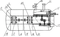
附图1是本发明结构示意图;附图2是附图1中高压釜罐结构示意图;附图3是附图2的俯视结构示意图;附图4是附图2中A-A剖视结构示意图,附图5是附图1中高压釜罐放大结构示意图,主要示意浇勺位置。Accompanying
具体实施方式 Detailed ways
对照附图及实施例,对本发明做进一步说明。The present invention will be further described with reference to the accompanying drawings and examples.
图中3是高压釜罐,高压釜罐3内安装导轨,高压釜罐3与压缩空气管路8一端连接,压缩空气管路8另一端与增压罐7连接,压缩空气管路8上安装进气电动球阀4,高压釜罐3上部开设第一浇注窗口17、第二浇注窗口18、第三浇注窗口14和第四浇注窗口43,第一浇注窗口17和第二浇注窗口18一侧安装第一气缸16,第一气缸16的活塞杆与第一连杆19连接,第一连杆19与第一浇注窗口盖20连接。第三浇注窗口14和第四浇注窗口43一侧安装第二气缸15,第二气缸15活塞杆与第二连接杆32连接,第二连接杆32与浇注窗口盖连接。高压釜罐3底部安装固定导轨21和活动导轨,活动导轨与气缸连接。高压釜罐3一端安装活动门27,活动门27与门连杆25连接,门连杆25一端与高压釜罐3连接,门连杆25是曲杆,呈弧状,便于顺利打开活动门27,并且使用寿命长,活动门27与第三气缸26连接。高压釜罐3一侧安装排气电动球阀5。高压釜罐3上部内侧安装第一挡板30和第二挡板31,用于启闭浇注口,便于更好的完成浇注,不产生浇注缺陷。第一挡板30通过连接件与第一连杆19连接,第二挡板31通过连接件与第二连杆32连接。本发明所述活动导轨为两条,第一活动导轨29下部与第一转轴39连接,第一转轴39通过连杆与第四气缸24连接,第二活动导轨22下部与第二转轴36连接,第二转轴36通过连杆与第五气缸38连接。高压釜罐3内壁上设置支撑筋34,以增加其强度。高压釜罐3外壁上安装真空压力表33、手动排气管40和自动排气管23。本发明使用时,将砂箱28吊装到电动台车上,电器系统先将高压釜罐3内的活动导轨通过气缸及连杆机构将其放倒,然后通过起动第三气缸26驱动门连杆25机构将活动门27打开,再通过电信号控制,通过气缸驱动连杆机构将活动导轨竖起,并与固定导轨相接之后,按动操作台上的开关,使电动台车沿导轨把砂箱平稳地移入到高压釜罐3内,再将活动门27关闭。此时,再起动第一气缸16、第二气缸15通过连杆机构打开浇注窗口,把加铝水用漏斗45从四个窗口放入到高压釜罐3内,并与四个浇勺对接,浇勺44位于砂箱浇口上方。由于浇勺44与摆动油缸12连接,所以可以控制其实现自动倾转浇注。当人工将四个浇包内的铝合金液缓慢通过漏斗倒入高压釜罐体内的浇勺中之后,然后将漏斗45取出,第一气缸16、第二气缸15驱动连杆机构关闭浇注窗口,此时,采用真空泵迅速将高压釜罐3内的气体抽出,达到设定的真空度后,浇勺44中的铝水再平缓倒入砂型中的型腔中。真空浇注完成后,进气电动球阀4打开,增压罐7内的压缩空气迅速充填到高压釜罐3中,并且在很短的时间内使高压釜罐3内的压力迅速增到0.6MPa,此时,铸型型腔内的铝水通过浇口和冒口实现在压力下凝固。本发明的铸件,由于是在真空浇注下完成,所以铝件组织致密,没有针孔,缩孔,缩松及二次夹渣等铸造缺陷。3 in the figure is an autoclave tank, a guide rail is installed in the
当铸件在压力下凝固后打开排气电动球阀5排气,当高压釜罐内的压力为零时,将活动导轨竖起,电动台车把砂箱移出罐体。When the casting is solidified under pressure, open the exhaust
图中6是阀门,13是真空泵,35是轴,41是挡板。6 is a valve among the figure, and 13 is a vacuum pump, and 35 is an axle, and 41 is a baffle plate.
Claims (4)
Priority Applications (3)
| Application Number | Priority Date | Filing Date | Title |
|---|---|---|---|
| CNB2007100149961A CN100464899C (en) | 2007-06-28 | 2007-06-28 | An aluminum alloy vacuum pouring device |
| US12/305,955 US8069902B2 (en) | 2007-06-28 | 2008-05-16 | Aluminum alloy vacuum casting equipment |
| PCT/CN2008/000953 WO2009000143A1 (en) | 2007-06-28 | 2008-05-16 | Aluminum alloy vacuum pouring device |
Applications Claiming Priority (1)
| Application Number | Priority Date | Filing Date | Title |
|---|---|---|---|
| CNB2007100149961A CN100464899C (en) | 2007-06-28 | 2007-06-28 | An aluminum alloy vacuum pouring device |
Publications (2)
| Publication Number | Publication Date |
|---|---|
| CN101108415A CN101108415A (en) | 2008-01-23 |
| CN100464899C true CN100464899C (en) | 2009-03-04 |
Family
ID=39040787
Family Applications (1)
| Application Number | Title | Priority Date | Filing Date |
|---|---|---|---|
| CNB2007100149961A Expired - Fee Related CN100464899C (en) | 2007-06-28 | 2007-06-28 | An aluminum alloy vacuum pouring device |
Country Status (3)
| Country | Link |
|---|---|
| US (1) | US8069902B2 (en) |
| CN (1) | CN100464899C (en) |
| WO (1) | WO2009000143A1 (en) |
Families Citing this family (7)
| Publication number | Priority date | Publication date | Assignee | Title |
|---|---|---|---|---|
| CN100464899C (en) * | 2007-06-28 | 2009-03-04 | 济南铸锻所捷迈机械有限公司 | An aluminum alloy vacuum pouring device |
| CN102581255B (en) * | 2012-03-13 | 2014-04-09 | 中国兵器工业第五九研究所 | Device and process for manufacturing large-scale complex thin-wall aluminum alloy casting through vacuum pressurization casting |
| CN105855521A (en) * | 2014-05-09 | 2016-08-17 | 重庆硕龙科技有限公司 | Method and device for gravity casting of light alloy |
| US20160121394A1 (en) * | 2014-10-30 | 2016-05-05 | Retech Systems Llc | Dual vacuum induction melting & casting |
| US10196951B2 (en) * | 2016-05-31 | 2019-02-05 | Boiler Tube Company Of America | Selective catalytic reactor (SCR) door systems |
| CN109093100B (en) * | 2018-08-09 | 2020-11-13 | 浙江纳迪克数控设备有限公司 | Device for casting aluminum alloy hub |
| CN117139588A (en) * | 2023-08-28 | 2023-12-01 | 台州学院 | An aluminum alloy forced shaping device and aluminum alloy heat treatment method |
Citations (5)
| Publication number | Priority date | Publication date | Assignee | Title |
|---|---|---|---|---|
| US3595303A (en) * | 1967-11-16 | 1971-07-27 | Eric J Ponting | Apparatus for casting molten substances |
| JPS609574A (en) * | 1983-06-29 | 1985-01-18 | M C L:Kk | Casting device |
| CN88202405U (en) * | 1988-04-04 | 1988-10-19 | 冶金工业部钢铁研究总院 | Injection method vacuum suction casting device |
| JPH0275461A (en) * | 1988-09-12 | 1990-03-15 | Mazda Motor Corp | Suction casting apparatus |
| CN1465458A (en) * | 2002-06-28 | 2004-01-07 | 李泽奇 | Sand mould vacuum pressure casting technology and equipment |
Family Cites Families (7)
| Publication number | Priority date | Publication date | Assignee | Title |
|---|---|---|---|---|
| CA970523A (en) * | 1971-06-22 | 1975-07-08 | Pavel V. Norin | Vacuum arc furnace |
| GB1340845A (en) * | 1972-03-10 | 1973-12-19 | Glazunov S G | Vacuum arc furnace |
| US4741384A (en) * | 1982-01-07 | 1988-05-03 | Gte Products Corporation | Apparatus for melting, casting and discharging a charge of metal |
| DE4038576A1 (en) * | 1990-12-04 | 1992-06-11 | Leybold Ag | DEVICE FOR TURNING AND PROCESSING A CHILLING TABLE IN A VACUUM MELTING AND FOUNDATION SYSTEM |
| DE4415855C1 (en) * | 1994-05-05 | 1995-05-24 | Leybold Durferrit Gmbh | Fine casting installation with a gas-lock unit |
| JP4422984B2 (en) * | 2003-07-23 | 2010-03-03 | 日本鋳造株式会社 | Atmosphere control type casting equipment |
| CN100464899C (en) * | 2007-06-28 | 2009-03-04 | 济南铸锻所捷迈机械有限公司 | An aluminum alloy vacuum pouring device |
-
2007
- 2007-06-28 CN CNB2007100149961A patent/CN100464899C/en not_active Expired - Fee Related
-
2008
- 2008-05-16 WO PCT/CN2008/000953 patent/WO2009000143A1/en not_active Ceased
- 2008-05-16 US US12/305,955 patent/US8069902B2/en not_active Expired - Fee Related
Patent Citations (5)
| Publication number | Priority date | Publication date | Assignee | Title |
|---|---|---|---|---|
| US3595303A (en) * | 1967-11-16 | 1971-07-27 | Eric J Ponting | Apparatus for casting molten substances |
| JPS609574A (en) * | 1983-06-29 | 1985-01-18 | M C L:Kk | Casting device |
| CN88202405U (en) * | 1988-04-04 | 1988-10-19 | 冶金工业部钢铁研究总院 | Injection method vacuum suction casting device |
| JPH0275461A (en) * | 1988-09-12 | 1990-03-15 | Mazda Motor Corp | Suction casting apparatus |
| CN1465458A (en) * | 2002-06-28 | 2004-01-07 | 李泽奇 | Sand mould vacuum pressure casting technology and equipment |
Non-Patent Citations (1)
| Title |
|---|
| 小型环氧树脂真空浇注设备. 赵会玲,张洪凯.真空,第6期. 1998 * |
Also Published As
| Publication number | Publication date |
|---|---|
| US8069902B2 (en) | 2011-12-06 |
| US20110162815A1 (en) | 2011-07-07 |
| CN101108415A (en) | 2008-01-23 |
| WO2009000143A1 (en) | 2008-12-31 |
Similar Documents
| Publication | Publication Date | Title |
|---|---|---|
| CN100464899C (en) | An aluminum alloy vacuum pouring device | |
| CN107876734B (en) | A kind of magnesium alloy differential pressure casting method | |
| CN104399881B (en) | The casting method of low-speed diesel for large-bore vessel bearing block steel-casting | |
| CN101168189A (en) | Vacuum differential pressure pressurization casting method and device | |
| CN204449263U (en) | Aluminum-alloy wheel casting machine | |
| CN106735086A (en) | A kind of casting device | |
| CN107900313A (en) | A kind of magnesium alloy automates air injection machine | |
| CN101249559B (en) | Multiple ingot vacuum running castings device and method for vacuum running castings using same | |
| CN204413128U (en) | Bottom filling servo-hydraulic casting machine | |
| US4262827A (en) | Ladle shroud apparatus | |
| CN116727648A (en) | Investment casting multifunctional casting transfer box | |
| CN203076542U (en) | Vacuum sand box capable of purifying flue gas | |
| CN209223128U (en) | A kind of aluminium alloy sand mould casting equipment | |
| CN206952113U (en) | Mold the feeding device in vacuum pouring system | |
| CN211499778U (en) | A central isolation pier automatic formwork trolley | |
| CN108580858A (en) | A kind of pouring manipulator | |
| CN117505814A (en) | A low-pressure casting pool-type holding furnace aluminum liquid conveying device and method thereof | |
| CN207103749U (en) | Double teeming road casting screen pack fetching device | |
| CN203875329U (en) | Lifting ladle support | |
| CN204353470U (en) | A kind of electric self-propelled apparatus for pouring | |
| CN115352819A (en) | Large-tonnage aluminum alloy melt transfer mechanism | |
| CN219335960U (en) | Molten iron casting furnace | |
| CN206882780U (en) | Casting auxiliary car | |
| CN213437113U (en) | Vacuum supercharging device of complicated thin-wall hollow casting | |
| CN207900224U (en) | A kind of used in aluminium alloy casting casting ladle |
Legal Events
| Date | Code | Title | Description |
|---|---|---|---|
| C06 | Publication | ||
| PB01 | Publication | ||
| C10 | Entry into substantive examination | ||
| SE01 | Entry into force of request for substantive examination | ||
| C14 | Grant of patent or utility model | ||
| GR01 | Patent grant | ||
| ASS | Succession or assignment of patent right |
Owner name: JI'NAN FOUNDRY + METALFORMING MACHINERY RESEARCH I Free format text: FORMER OWNER: JINAN CASTING + FORGING JIEMAI MACHINERY CO., LTD. Effective date: 20110104 |
|
| C41 | Transfer of patent application or patent right or utility model | ||
| COR | Change of bibliographic data |
Free format text: CORRECT: ADDRESS; FROM: 250022 FOUNDRY MACHINERY BRANCH, JI'NAN FOUNDRY + METALFORMING MACHINERY RESEARCH INSTITUTE CO., LTD., NO.646, JINGSHI ROAD, JI'NAN CITY, SHANDONG PROVINCE TO: 250306 NO.500, FENGHUANG ROAD, CHANGQING DISTRICT, JI'NAN CITY, SHANDONG PROVINCE |
|
| TR01 | Transfer of patent right |
Effective date of registration: 20110104 Address after: 250306 Phoenix Road, Changqing District, Shandong, Ji'nan, China, 500 Patentee after: Ji'nan Foundry & Metalforming Machinery Research Institute Co., Ltd. Address before: 250022 Shandong city of Ji'nan province by ten Road No. 464 Ji'nan JFMMRI Jiemai Machinery Co Ltd casting machinery branch Patentee before: Jinan Casting & Forging Jiemai Machinery Co., Ltd. |
|
| CF01 | Termination of patent right due to non-payment of annual fee |
Granted publication date: 20090304 Termination date: 20190628 |
|
| CF01 | Termination of patent right due to non-payment of annual fee |
