CN100464503C - Method and apparatus for adjusting clock signal - Google Patents
Method and apparatus for adjusting clock signal Download PDFInfo
- Publication number
- CN100464503C CN100464503C CNB2006101272189A CN200610127218A CN100464503C CN 100464503 C CN100464503 C CN 100464503C CN B2006101272189 A CNB2006101272189 A CN B2006101272189A CN 200610127218 A CN200610127218 A CN 200610127218A CN 100464503 C CN100464503 C CN 100464503C
- Authority
- CN
- China
- Prior art keywords
- frequency
- clock signal
- input data
- time point
- sampling
- Prior art date
- Legal status (The legal status is an assumption and is not a legal conclusion. Google has not performed a legal analysis and makes no representation as to the accuracy of the status listed.)
- Active
Links
- 238000000034 method Methods 0.000 title claims abstract description 30
- 238000005070 sampling Methods 0.000 claims abstract description 32
- 238000006243 chemical reaction Methods 0.000 claims abstract 38
- 230000003111 delayed effect Effects 0.000 claims description 9
- 230000004044 response Effects 0.000 claims description 8
- 238000013519 translation Methods 0.000 claims description 8
- 230000003247 decreasing effect Effects 0.000 claims 5
- 238000011084 recovery Methods 0.000 abstract description 8
- 230000009471 action Effects 0.000 abstract description 6
- 230000005540 biological transmission Effects 0.000 abstract description 5
- 239000012071 phase Substances 0.000 description 33
- 238000010586 diagram Methods 0.000 description 15
- 230000001105 regulatory effect Effects 0.000 description 5
- 238000005516 engineering process Methods 0.000 description 4
- 230000007704 transition Effects 0.000 description 4
- 230000008859 change Effects 0.000 description 3
- 238000009825 accumulation Methods 0.000 description 2
- 230000008034 disappearance Effects 0.000 description 2
- 230000006872 improvement Effects 0.000 description 2
- 238000013461 design Methods 0.000 description 1
- 238000011161 development Methods 0.000 description 1
- 238000007599 discharging Methods 0.000 description 1
- 230000008030 elimination Effects 0.000 description 1
- 238000003379 elimination reaction Methods 0.000 description 1
- 239000008384 inner phase Substances 0.000 description 1
- 230000007246 mechanism Effects 0.000 description 1
- 238000012545 processing Methods 0.000 description 1
- 230000036632 reaction speed Effects 0.000 description 1
Images


Landscapes
- Synchronisation In Digital Transmission Systems (AREA)
Abstract
The invention is a method and device for adjusting a clock signal, which is used to adjust the frequency of a clock signal according to the frequency of an input data, the device includes: a first frequency doubling sampling-statistical judging circuit; a first flip-flop and a logic decision circuit, wherein the bit time of the input data is defined into at least two regions, and the method comprises: sampling the input data by the frequency multiplication of the clock pulse signal; sampling the input data to obtain a distribution waveform of a data conversion time point; and defining the bit time of the input data as at least two regions, and judging to increase or decrease the frequency of the clock pulse signal according to the moving condition of the distribution waveform of the data conversion time point in the bit time. The method and the device for adjusting the clock pulse signal eliminate the difference between the transmission rate of the input data and the frequency of the clock pulse signal, and stably lock the data to perform recovery action.
Description
Technical field
The present invention is a kind of time-vein signal regulating method and device, refers to be applied to string type input data and a this locality especially with reference to time-vein signal regulating method between clock pulse and device.
Background technology
For the asynchronous string type bus of high speed (high speed un-synchronousserial bus), clock-data recovery technology (Clock Data Recovery, be called for short CDR) is that this type of is imported at a high speed/key technology of outgoing interface.See also Fig. 1, it is one commonly used with phase-locked loop (Phase Lock Loop, be called for short PLL) be the partial function block schematic diagram of the basic clock-data recovery circuit of being finished, wherein be to be provided with a phase (Phase/Frequency Detector) 11, and in frequency mode (Frequency mode), it is that phase difference between a clock pulse signal CK who is sent with reference to clock pulse (ref-clock) and voltage-controlled oscillator 16 according to a this locality is exported a up/down pulse wave signal, when this locality was higher than the frequency of clock signal CK with reference to the frequency of clock pulse, the output of phase 11 can be exported (Up) pulse wave signal upwards; If otherwise when local frequency with reference to clock pulse was lower than the frequency of clock signal CK, output can be exported (Down) pulse wave signal downwards.Thus, the pulse wave signal that phase 11 is produced charges and discharge device 14 (ChargePump) and loop filter 15 (Loop Filter) via electric charge subsequently, be converted into afterbody-voltage-controlled oscillator 16 (Voltage Controlled Oscillator, abbreviation VCO) control voltage, and then make the clock signal CK of these voltage-controlled oscillator 16 outputs move closer to this this locality with reference to clock pulse (ref-clock), up to the difference on the frequency of clock signal CK seldom with this this locality with reference to clock pulse (ref-clock) when identical, system just controls this multiplexer 13 and switches to a phase pattern (Phase mode), promptly begins to utilize frequency and this this locality with reference to the much the same clock signal CK of clock pulse (ref-clock) the data Rdata that receives to be taken a sample.
And because when transmitting data with the asynchronous serial mode of above-mentioned high speed, and can't produce certain sampling frequency according to the waveform of the data Rdata that receives itself, when therefore entering this phase pattern (Phase mode), clock pulse data recovery technique commonly used just needs a phase detector (Phase Detector) 12 to detect reception data and inner phase difference of taking a sample between clock pulse (being above-mentioned clock signal CK), pass through to adjust the phase place of above-mentioned clock signal CK again, and then can stably pin data and recover action.But using two kinds of different clock pulse sources or the low-frequency power/ground noise (low frequency power/ground noise) between interface between two interfaces, all will allow the transmission rate of data Rdata and local becoming to avoid and to be difficult to prediction with reference to the frequency difference between clock pulse (ref-clock) (freqency difference).And if above-mentioned both frequency difference values are excessive, above-mentioned usual means will have problems when the data Rdata that receives is locked in this phase pattern (Phasemode), because phase detector (Phase Detector) commonly used still has its limit to exist for the aspect of following the trail of (track) frequency change, so under old design idea, clock pulse data recovery technique commonly used is under the excessive situation of frequency difference, even improve the reaction speed of the phase-locked loop (PLL) that is wherein used, still probably can't effectively pin data and carry out data recovery action.
Summary of the invention
In view of this, how developing the technological means that the above-mentioned mechanism disappearance commonly used of effective improvement, is main purpose of the present invention.
The present invention is the method for adjusting for a kind of clock signal, and in order to adjust a frequency with reference to clock pulse according to an input data frequency, this method includes: with the frequency multiplication of this clock signal this input data of taking a sample; Take a sample these input data to obtain the distribution waveform of a data transaction time point; And the bit time that defines these input data is at least two districts, in the mobile situation of this bit time, judges the frequency that increases or reduce this clock signal according to the distribution waveform of this data transaction time point.
Another aspect of the present invention is to be a kind of clock signal adjusting device, in order to adjust the frequency of a clock pulse signal according to an input data frequency, this device includes: one first frequency multiplication sampling-statistics decision circuitry, in order to receive this input data, and with the frequency multiplication of this clock signal this input data of taking a sample, and export the distribution waveform of one first data transaction time point; One first flip-flop is connected to this first frequency multiplication sampling-statistics decision circuitry, exports after receiving the distribution waveform of this first data transaction time point and the distribution waveform with this first data transaction time point of frequency sample of this clock signal; And a logic judging circuit, be connected to this first flip-flop, judge the situation of the distribution waveform sampling translation of this first data transaction time point; Wherein the bit time of these input data is defined as at least two districts, according to the situation that moves in this bit time after the distribution waveform sampling of this first data transaction time point, increases or reduce the frequency of this clock signal.
Of the present invention is to be a kind of time-vein signal regulating method more on the one hand, in order to adjust a clock pulse signal according to input data, with reference to clock pulse, its method comprises the following step: adjust the frequency of this clock signal with reference to the frequency difference between clock pulse and this clock signal according to this; Adjust the frequency of this clock signal according to the frequency difference between this input data frequency and this clock signal; And the phase place of adjusting this clock signal according to the phase place and the phase difference between this clock signal of these input data, in order to the adjustment of finishing this clock signal and utilize this clock signal to handle this input data.
Time-vein signal regulating method of the present invention and device have been eliminated the transmission rate of input data and the frequency difference of clock signal, have stably pinned data and have recovered action.
Description of drawings
Fig. 1 is the partial function block schematic diagram of a clock-data recovery circuit of being finished for the basis with phase-locked loop (Phase Lock Loop is called for short PLL) commonly used;
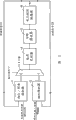
Fig. 2 is that the present invention is the function block schematic diagram that improves the clock pulse sig-nal-conditioning unit that conventional means develops out;
Fig. 3 is the control signal waveform schematic diagram of the present invention's first multiplexer and second multiplexer;
Fig. 4 is the distribution schematic diagram that string type input data is carried out the back data transaction time point that is produced of double frequency sampling;
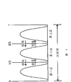
To be the present invention carry out carrying out double frequency sampling (being the twice of clock pulse signal CK) again after the delay of a period of time to these string type input data Fig. 5, and then a normal distribution waveform 50 that is separated into and a schematic diagram that postpones back distribution waveform 51;
Fig. 6 is the preferred embodiment function block schematic diagram of the present invention about the data frequency detector;
The take a sample distribution schematic diagram of resulting data transaction time point of Fig. 7 frequency tripling that to be the present invention carry out a specific quantity to these string type input data;
Fig. 8 is another preferred embodiment function block schematic diagram of data frequency detector of the present invention.
Embodiment
Please earlier referring to Fig. 2, it is that the present invention is the function block schematic diagram that improves the clock pulse sig-nal-conditioning unit that conventional means develops out, its device consists predominantly of a phase-locked loop main body 20, a phase 21, a data frequency detector 22, a phase detector 23, one first multiplexer 24, one second multiplexer 25, and its operation procedure is as described below:
At first, system just enters one first state at the beginning, in this first state, phase 21 is to send first and adjust signal SD1 with reference to the frequency difference between a clock pulse signal CK of clock pulse ref-clock and 20 outputs of this phase-locked loop main body in response to this locality, and then adjusts the frequency of this clock signal CK of phase-locked loop main body 20 outputs.So, when this this locality is exported the frequency of this clock signal CK with reference to the frequency of clock pulse ref-clock greater than this phase-locked loop, just the frequency with clock signal CK adjusts upward, as for when this this locality is exported the frequency of this clock signal CK with reference to the frequency of clock pulse ref-clock less than this phase-locked loop, just the frequency of this clock signal CK is adjusted downwards.Thus, after adjustment after a while, the frequency of clock signal CK just can be approached local frequency with reference to clock pulse ref-clock gradually.
Therefore, after the enough approaching local frequency of the frequency of clock pulse signal CK with reference to clock pulse ref-clock, system just can switch to second state by first state, and in this second state, system uses data frequency detector 22 instead to send second with the frequency difference between clock signal CK in response to the signal frequency of this string type input data Rdata and adjust signal SD2, and then the frequency of adjustment clock signal CK.Thus, after adjustment after a while, the frequency of clock signal CK just can be approached the signal frequency (being message transmission rate) of string type input data Rdata gradually in this state, and then the transmission rate of elimination string type input data Rdata and local with reference to the frequency difference between clock pulse (ref-clock) (frequency difference).
Thus, system just switches to a third state by this second state again, use phase detector 23 instead and send the 3rd adjustment signal SD3 with the phase difference between this clock signal CK in response to the signal phase of this string type input data Rdata, and then the phase place of adjustment clock signal CK, and can further utilize this clock signal CK to come these string type input data are carried out the processing that data are recovered.
Switch to second state and can switch by the control signal that changes first multiplexer 24 and second multiplexer 25 by first state as for above-mentioned by the action that second state switches to the third state, its signal switch schematic diagram see also Fig. 3 shown in.Wherein the control signal of first multiplexer 24 and second multiplexer 25 is respectively (Mux1, Mux2), when (Mux1, Mux2)=(0,0) just represents first state time, and work as (Mux1, Mux2)=(x, 1) Shi Ze representative switches to second state (x represent 0 or 1 all can), as (Mux1, Mux2)=(1,0) time, then representative switches to the third state.
And how to adjust the frequency of this clock signal CK of this phase-locked loop main body 20 outputs, and then dwindle and this string type input data Rdata signal between frequency difference, data frequency detector 22 is to play the part of important role, it mainly is to send second in response to the frequency difference between this clock signal of this string type input data Rdata and 20 outputs of this phase-locked loop main body to adjust signal SD2, when the frequency of clock pulse signal CK is imported the signal frequency of data Rdata greater than this string type, the frequency of clock signal CK is adjusted downwards, and when the frequency of clock pulse signal CK was imported the signal frequency of data Rdata less than this string type, just the frequency with clock signal CK adjusted upward.Thus, the frequency of clock signal CK just can be approached the signal frequency of these string type input data Rdata gradually.And can clearly demonstrating data frequency detector 22, following narration how can reach above-mentioned functions.
Because the waveform that can't directly see through string type input data Rdata is detected the variation of its signal frequency, so must carry out the double frequency sampling (being the twice of clock pulse signal CK) of a specific quantity (for example 10 bit times) to these string type input data Rdata, and then obtain the distribution schematic diagram of data transaction (Data transition) time point as shown in Figure 4.Judge for convenience, the bit time (bittime) of string type input data Rdata is divided into two districts so that tentatively this distribution waveform position is defined in first district or second district.Then by after continuing that these string type input data Rdata carried out double frequency sampling, the moving direction of observing this distribution waveform is again judged the magnitude relationship between the frequency of this string type input data Rdata signal frequency and clock signal CK, because when both are variant, the distribution waveform of this data transaction (Data transition) time point just can begin translation.Wherein when this string type input data Rdata signal frequency during greater than the frequency of clock signal CK, distribution waveform 40 just can become distribution waveform 41 to left, otherwise, when this string type input data Rdata signal frequency during less than the frequency of clock signal CK, distribution waveform just can become distribution waveform 42 to right translation.But it is very unfortunate, under the example of this double frequency sampling, originally be positioned at the distribution waveform in first district, no matter be translation to the left or to the right, therefore all can be observed at last and move to second district, can't effectively judge the magnitude relationship between the frequency of this string type input data Rdata signal frequency and clock signal CK.
So, for solving this problem, just this string type input data Rdata is carried out carrying out double frequency sampling (being the twice of clock pulse signal CK) again after the delay of a period of time, a normal distribution waveform 50 and that forms as shown in Figure 5 postpones back distribution waveform 51.Thus,, just can know and tell mobile direction, and then judge magnitude relationship between the frequency of this string type input data Rdata signal frequency and clock signal CK according to tabulating 1 judgment standard down.
Table 1
| The position moving direction of normal distribution waveform | Move the position that postpones the back distribution waveform | Magnitude relationship |
| Move to second district from first district | Maintain first district | The Rdata signal frequency is greater than clock signal CK |
| Maintain first district | Move to second district from first district | The Rdata signal frequency is less than clock signal CK |
| Move to first district from second district | Maintain second district | The Rdata signal frequency is greater than clock signal CK |
| Maintain second district | Move to first district from second district | The Rdata signal frequency is less than clock signal CK |
So according to above-mentioned phenomenon, just develop the data frequency detector preferred embodiment function block schematic diagram 22 that comes out as shown in Figure 6, it consists predominantly of a delay cell 220, one first double frequency sampling-statistics decision circuitry 221, one second double frequency sampling-statistics decision circuitry 222, first flip-flop 223, second flip-flop 224 and logic judging circuit 225, wherein this delay cell 220 is to receive these string type input data Rdata, and export after this string type input data Rdata postponed to reach a scheduled time, this scheduled time is less than the bit time of these string type input data, 1/4 bit time for example, first double frequency sampling-statistics the decision circuitry 221 and second double frequency sampling-statistics decision circuitry 222 then, just receive respectively this string type input data Rdata with delayed after this string type input data Rdata_delay and carry out double frequency to take a sample and obtain a series of sampling point, and after reaching a predetermined quantity, the sampling point accumulation adds up, and (for example: logical one) send one first numerical value more for a long time in the quantity that sampling point is arranged in one first time domain (the first above-mentioned district) of two time domains, represent this string type input data Rdata or delayed after the distribution waveform of these string type input data Rdata_delay be positioned at first district, and in the quantity that these sampling points are arranged in one second time domain (the second above-mentioned district) of two time domains send more for a long time a second value (for example: logical zero), represent this string type input data Rdata or delayed after the distribution waveform of these string type input data Rdata_delay be positioned at second district.Moreover, 224 of second flip-flops that are electrically connected on first flip-flop 223 of this first double frequency sampling-statistics decision circuitry 221 and are electrically connected on this second double frequency sampling-statistics decision circuitry 222 receive this first numerical value or this second value respectively and postpone to export behind this bit time, be electrically connected on this first double frequency sampling-statistics decision circuitry 221 at last, this second double frequency sampling-statistics decision circuitry 222, first flip-flop 223, this logic judging circuit 225 of this second flip-flop 224 and this second multiplexer 25, it is to send this second adjustment signal SD2 in response to the numerical value change of these circuit outputs according to 2 truth tables (truth table) that disclose of tabulating down.
Table 2
| up | up-p | up-delay | up-delay-p | up- |
| 1 | 0 | 1 | 1 | 1 |
| 0 | 1 | 0 | 0 | 1 |
| 1 | 1 | 1 | 0 | 0 |
| 0 | 0 | 0 | 1 | 0 |
Wherein up, up-delay, up-p, up-delay-p represent the output signal of the first double frequency sampling-statistics decision circuitry 221, this second double frequency sampling-statistics decision circuitry 222, first flip-flop 223 and second flip-flop 224 respectively, and on behalf of distribution waveform, logical one be positioned at first district, and on behalf of distribution waveform, logical zero then be positioned at second district.Thus, logic judging circuit 225 just can be according to the continuous variation of moving of two distribution waveform, tell the magnitude relationship of Rdata signal frequency and clock signal CK frequency, and then change the state of its output signal up-freq, when up-freq is the logical one interval scale frequency of clock signal CK is adjusted upward, and when up-freq is logical zero, just the frequency of clock signal CK is adjusted downwards.
Mainly charging and discharging device 201, loop filter 202 and voltage-controlled oscillator 203 by electric charge as for this phase-locked loop main body 20 is constituted, wherein the electric charge action that charges and discharge device 201, loop filter 202 and voltage-controlled oscillator 203 itself and conventional means there is no different, so do not repeat them here.But its annexation then is electrically connected on this second multiplexer 25 for this electric charge charges and discharge device 201, and being electrically connected on this electric charge, loop filter 202 charges and discharge device 201, be electrically connected on this loop filter 202, this phase 21, this data frequency detector 22 and this phase detector 23 as for 203 of this voltage-controlled oscillators, it is a frequency of adjusting this clock signal CK of its output in response to the output of this loop filter 202.
In addition, see also Fig. 7 again, it is the frequency tripling sampling (be clock pulse signal CK three times) of this string type input data Rdata being carried out a specific quantity (for example 10 bit times), and then the distribution schematic diagram of the data transaction that obtains (Data transition) time point.Thus, the bit time (bit time) of string type input data Rdata will be divided into three districts so that tentatively this distribution waveform position is defined in first district, second district or the 3rd district.And in this example, after continuing that these string type input data Rdata carried out the frequency tripling sampling, the moving direction of observing this distribution waveform more continuously just can directly be judged the magnitude relationship between the frequency of this string type input data Rdata signal frequency and clock signal CK, because when both are variant, the distribution waveform of this data transaction (Data transition) time point just can begin translation.Wherein when this string type input data Rdata signal frequency during greater than the frequency of clock signal CK, distribution waveform just can be to left, so the order that moves just can present the order in the 3rd district → second district → first district.Otherwise when this string type input data Rdata signal frequency during less than the frequency of clock signal CK, distribution waveform just can be to right translation, so the order that moves just can present the order in first district → second district → the 3rd district.So just can effectively judge the magnitude relationship between the frequency of this string type input data Rdata signal frequency and clock signal CK.
So, another preferred embodiment function block schematic diagram of data frequency detector of the present invention as shown in Figure 8 just is developed, it consists predominantly of a frequency tripling sampling-statistics decision circuitry 80, one flip-flop 81 and logic judging circuit 82, wherein this frequency tripling sampling-statistics decision circuitry 80 is to receive these string type input data Rdata, carry out the frequency tripling sampling then and obtain a series of sampling point, and after reaching a predetermined quantity, the sampling point accumulation adds up, and when distribution waveform is positioned at first district, its output signal S0 is with output logic " 1 ", if distribution waveform is not when first district, then output signal S0 is with output logic " 0 ", in like manner, when distribution waveform was positioned at second district, its output signal S1 was with output logic " 1 ", if distribution waveform is not when second district, then output signal S1 is output logic " 0 ", and when distribution waveform was positioned at the 3rd district, its output signal S2 was with output logic " 1 ", if distribution waveform is not when the 3rd district, then output signal S2 is with output logic " 0 ".And flip-flop 81 receives these output signals S0, S1, S2 postpones all after dates of a clock pulse signal CK, produce the output signal S0_P after postponing, S1_P, S2_P, this logic judging circuit 82 is then in response to these output signals S0, S1, S2, S0_P, S1_P, the variation of S2_P and send this according to 3 truth tables (truth table) that disclose of tabulating down and second adjust signal up-freq, wherein up-freq=0 represents the frequency of string type input data Rdata signal frequency less than clock signal CK, so clock signal CK will be turned down, up-freq=1 then represents the frequency of string type input data Rdata signal frequency greater than clock signal CK, so clock signal CK will be heightened.
Table 3
| S0_P | S1_P | S2_P | S0 | S1 | S2 | Up- |
| 1 | 0 | 0 | 0 | 1 | 0 | 0 |
| 0 | 1 | 0 | 0 | 0 | 1 | 0 |
| 0 | 0 | 1 | 1 | 0 | 0 | 0 |
| 1 | 0 | 0 | 0 | 0 | 1 | 1 |
| 0 | 1 | 0 | 1 | 0 | 0 | 1 |
| 0 | 0 | 1 | 0 | 1 | 0 | 1 |
In sum, the present invention develops the difference that a plurality of embodiment method and apparatus that all can effectively detect frequency between string type input data Rdata signal frequency and clock signal CK, and then effectively improve the disappearance of above-mentioned conventional means, and then reach development main purpose of the present invention.Certainly, except the sample rate of two frequencys multiplication and frequency tripling, the sample rate of other higher frequency multiplication also is to reach purpose of the present invention, but it has been the technique variation that can simply know by inference, so do not repeat them here.
The above only is preferred embodiment of the present invention; so it is not in order to limit scope of the present invention; any personnel that are familiar with this technology; without departing from the spirit and scope of the present invention; can do further improvement and variation on this basis, so the scope that claims were defined that protection scope of the present invention is worked as with the application is as the criterion.
Being simply described as follows of symbol in the accompanying drawing:
Phase/frequency detector: 11
Voltage-controlled oscillator: 16
Electric charge charges and discharge device: 14
Loop filter: 15
Multiplexer: 13
Phase detector: 12
Phase-locked loop main body: 20
Phase/frequency detector: 21
Data frequency detector: 22
Phase detector: 23
First multiplexer: 24
Second multiplexer: 25
Electric charge charges and discharge device: 201
Loop filter: 202
Voltage-controlled oscillator: 203
Distribution waveform: 40,41,42
Normal distribution waveform: 50
Postpone the back distribution waveform: 51
Delay cell: 220
The first double frequency sampling-statistics decision circuitry: 221
The second double frequency sampling-statistics decision circuitry: 222
First flip-flop: 223
Second flip-flop: 224
Logic judging circuit: 225
Frequency tripling sampling-statistics decision circuitry: 80
Flip-flop: 81
Logic judging circuit: 82
Claims (18)
Priority Applications (1)
| Application Number | Priority Date | Filing Date | Title |
|---|---|---|---|
| CNB2006101272189A CN100464503C (en) | 2006-09-12 | 2006-09-12 | Method and apparatus for adjusting clock signal |
Applications Claiming Priority (1)
| Application Number | Priority Date | Filing Date | Title |
|---|---|---|---|
| CNB2006101272189A CN100464503C (en) | 2006-09-12 | 2006-09-12 | Method and apparatus for adjusting clock signal |
Publications (2)
| Publication Number | Publication Date |
|---|---|
| CN1921315A CN1921315A (en) | 2007-02-28 |
| CN100464503C true CN100464503C (en) | 2009-02-25 |
Family
ID=37778925
Family Applications (1)
| Application Number | Title | Priority Date | Filing Date |
|---|---|---|---|
| CNB2006101272189A Active CN100464503C (en) | 2006-09-12 | 2006-09-12 | Method and apparatus for adjusting clock signal |
Country Status (1)
| Country | Link |
|---|---|
| CN (1) | CN100464503C (en) |
Families Citing this family (4)
| Publication number | Priority date | Publication date | Assignee | Title |
|---|---|---|---|---|
| CN103684440B (en) * | 2012-09-04 | 2017-10-27 | 瑞昱半导体股份有限公司 | Clock and data recovery circuit and clock and data recovery method |
| CN105099410B (en) * | 2014-05-16 | 2018-08-28 | 瑞昱半导体股份有限公司 | Clock pulse data reflex circuit and method and grade signal analysis circuit and method |
| CN104965169A (en) * | 2015-07-29 | 2015-10-07 | 江苏杰进微电子科技有限公司 | Full-automatic IC electric signal test device and test method |
| JP6476325B1 (en) * | 2018-02-01 | 2019-02-27 | 華邦電子股▲ふん▼有限公司Winbond Electronics Corp. | Pseudo SRAM and control method thereof |
Citations (2)
| Publication number | Priority date | Publication date | Assignee | Title |
|---|---|---|---|---|
| CN1286532A (en) * | 1999-08-26 | 2001-03-07 | 阿尔卡塔尔公司 | Phase-locked loop frequency synthesizer |
| CN1307406A (en) * | 2000-01-27 | 2001-08-08 | 华为技术有限公司 | Filtering method of digital phase lock loop |
-
2006
- 2006-09-12 CN CNB2006101272189A patent/CN100464503C/en active Active
Patent Citations (2)
| Publication number | Priority date | Publication date | Assignee | Title |
|---|---|---|---|---|
| CN1286532A (en) * | 1999-08-26 | 2001-03-07 | 阿尔卡塔尔公司 | Phase-locked loop frequency synthesizer |
| CN1307406A (en) * | 2000-01-27 | 2001-08-08 | 华为技术有限公司 | Filtering method of digital phase lock loop |
Also Published As
| Publication number | Publication date |
|---|---|
| CN1921315A (en) | 2007-02-28 |
Similar Documents
| Publication | Publication Date | Title |
|---|---|---|
| US6041090A (en) | Data sampling and recover in a phase-locked loop (PLL) | |
| US5850422A (en) | Apparatus and method for recovering a clock signal which is embedded in an incoming data stream | |
| JP4515111B2 (en) | Data restoration apparatus and restoration method thereof | |
| CN100508399C (en) | Locking loop and synchronization method | |
| JP2783470B2 (en) | Digital clock conversion circuit | |
| US8023605B2 (en) | Oversampling circuit and oversampling method | |
| US7889816B2 (en) | Clock and data recovery circuit and communications apparatus including the clock and data recovery circuit | |
| Hsu et al. | An all-digital phase-locked loop (ADPLL)-based clock recovery circuit | |
| EP0653860A2 (en) | Digital phase alignment and integrated multichannel transceiver employing same | |
| EP2617135A1 (en) | Techniques for varying a periodic signal based on changes in a data rate | |
| US8537947B2 (en) | Oversampling circuit, serial communication apparatus and oversampling method | |
| US20040114702A1 (en) | Bang-bang phase detector for full-rate and half-rate schemes clock and data recovery and method therefor | |
| US6229358B1 (en) | Delayed matching signal generator and frequency multiplier using scaled delay networks | |
| US20070280392A1 (en) | Clock and data recovery method and corresponding device | |
| CN100464503C (en) | Method and apparatus for adjusting clock signal | |
| CN117639768A (en) | Lock detection circuit of phase-locked loop | |
| US7916822B2 (en) | Method and apparatus for reducing latency in a clock and data recovery (CDR) circuit | |
| Mesgarzadeh et al. | A new mesochronous clocking scheme for synchronization in SoC | |
| JPH11261409A (en) | Over sampling type clock recovery circuit | |
| Kang et al. | A CMOS high-speed data recovery circuit using the matched delay sampling technique | |
| TW200539562A (en) | High frequency binary phase detector | |
| US7194057B2 (en) | System and method of oversampling high speed clock/data recovery | |
| US7151810B2 (en) | Data and clock synchronization in multi-channel communications | |
| CN100416693C (en) | Clock data recovery circuit with phase selection circuit | |
| Alser et al. | Design and FPGA implementation of PLL-based quarter-rate clock and data recovery circuit |
Legal Events
| Date | Code | Title | Description |
|---|---|---|---|
| C06 | Publication | ||
| PB01 | Publication | ||
| C10 | Entry into substantive examination | ||
| SE01 | Entry into force of request for substantive examination | ||
| C14 | Grant of patent or utility model | ||
| GR01 | Patent grant |