CN100462905C - Portable device having rotatable input buttons and method of operating the same - Google Patents
Portable device having rotatable input buttons and method of operating the same Download PDFInfo
- Publication number
- CN100462905C CN100462905C CNB2006101682342A CN200610168234A CN100462905C CN 100462905 C CN100462905 C CN 100462905C CN B2006101682342 A CNB2006101682342 A CN B2006101682342A CN 200610168234 A CN200610168234 A CN 200610168234A CN 100462905 C CN100462905 C CN 100462905C
- Authority
- CN
- China
- Prior art keywords
- load button
- rotation
- mancarried device
- button
- load
- Prior art date
- Legal status (The legal status is an assumption and is not a legal conclusion. Google has not performed a legal analysis and makes no representation as to the accuracy of the status listed.)
- Expired - Fee Related
Links
Images


Classifications
-
- H—ELECTRICITY
- H04—ELECTRIC COMMUNICATION TECHNIQUE
- H04B—TRANSMISSION
- H04B1/00—Details of transmission systems, not covered by a single one of groups H04B3/00 - H04B13/00; Details of transmission systems not characterised by the medium used for transmission
- H04B1/38—Transceivers, i.e. devices in which transmitter and receiver form a structural unit and in which at least one part is used for functions of transmitting and receiving
- H04B1/40—Circuits
-
- G—PHYSICS
- G06—COMPUTING; CALCULATING OR COUNTING
- G06F—ELECTRIC DIGITAL DATA PROCESSING
- G06F3/00—Input arrangements for transferring data to be processed into a form capable of being handled by the computer; Output arrangements for transferring data from processing unit to output unit, e.g. interface arrangements
- G06F3/01—Input arrangements or combined input and output arrangements for interaction between user and computer
- G06F3/02—Input arrangements using manually operated switches, e.g. using keyboards or dials
- G06F3/0202—Constructional details or processes of manufacture of the input device
-
- G—PHYSICS
- G06—COMPUTING; CALCULATING OR COUNTING
- G06F—ELECTRIC DIGITAL DATA PROCESSING
- G06F3/00—Input arrangements for transferring data to be processed into a form capable of being handled by the computer; Output arrangements for transferring data from processing unit to output unit, e.g. interface arrangements
- G06F3/01—Input arrangements or combined input and output arrangements for interaction between user and computer
- G06F3/048—Interaction techniques based on graphical user interfaces [GUI]
- G06F3/0481—Interaction techniques based on graphical user interfaces [GUI] based on specific properties of the displayed interaction object or a metaphor-based environment, e.g. interaction with desktop elements like windows or icons, or assisted by a cursor's changing behaviour or appearance
- G06F3/0482—Interaction with lists of selectable items, e.g. menus
-
- G—PHYSICS
- G06—COMPUTING; CALCULATING OR COUNTING
- G06F—ELECTRIC DIGITAL DATA PROCESSING
- G06F3/00—Input arrangements for transferring data to be processed into a form capable of being handled by the computer; Output arrangements for transferring data from processing unit to output unit, e.g. interface arrangements
- G06F3/01—Input arrangements or combined input and output arrangements for interaction between user and computer
- G06F3/048—Interaction techniques based on graphical user interfaces [GUI]
- G06F3/0484—Interaction techniques based on graphical user interfaces [GUI] for the control of specific functions or operations, e.g. selecting or manipulating an object, an image or a displayed text element, setting a parameter value or selecting a range
-
- G—PHYSICS
- G06—COMPUTING; CALCULATING OR COUNTING
- G06F—ELECTRIC DIGITAL DATA PROCESSING
- G06F3/00—Input arrangements for transferring data to be processed into a form capable of being handled by the computer; Output arrangements for transferring data from processing unit to output unit, e.g. interface arrangements
- G06F3/01—Input arrangements or combined input and output arrangements for interaction between user and computer
- G06F3/048—Interaction techniques based on graphical user interfaces [GUI]
- G06F3/0487—Interaction techniques based on graphical user interfaces [GUI] using specific features provided by the input device, e.g. functions controlled by the rotation of a mouse with dual sensing arrangements, or of the nature of the input device, e.g. tap gestures based on pressure sensed by a digitiser
- G06F3/0489—Interaction techniques based on graphical user interfaces [GUI] using specific features provided by the input device, e.g. functions controlled by the rotation of a mouse with dual sensing arrangements, or of the nature of the input device, e.g. tap gestures based on pressure sensed by a digitiser using dedicated keyboard keys or combinations thereof
- G06F3/04892—Arrangements for controlling cursor position based on codes indicative of cursor displacements from one discrete location to another, e.g. using cursor control keys associated to different directions or using the tab key
-
- H—ELECTRICITY
- H04—ELECTRIC COMMUNICATION TECHNIQUE
- H04M—TELEPHONIC COMMUNICATION
- H04M1/00—Substation equipment, e.g. for use by subscribers
- H04M1/02—Constructional features of telephone sets
- H04M1/23—Construction or mounting of dials or of equivalent devices; Means for facilitating the use thereof
- H04M1/233—Construction or mounting of dials or of equivalent devices; Means for facilitating the use thereof including a pointing device, e.g. roller key, track ball, rocker switch or joystick
-
- H—ELECTRICITY
- H04—ELECTRIC COMMUNICATION TECHNIQUE
- H04M—TELEPHONIC COMMUNICATION
- H04M1/00—Substation equipment, e.g. for use by subscribers
- H04M1/72—Mobile telephones; Cordless telephones, i.e. devices for establishing wireless links to base stations without route selection
- H04M1/724—User interfaces specially adapted for cordless or mobile telephones
- H04M1/72469—User interfaces specially adapted for cordless or mobile telephones for operating the device by selecting functions from two or more displayed items, e.g. menus or icons
Abstract
A portable device having rotatable input buttons and a method of operating the portable device are provided. The portable device includes a button rotation detecting unit, a User Interface (UI) generating unit and a mode setting unit. The button rotation detecting unit detects the rotation of the input buttons. The UI generating unit generates desired objects. The mode setting unit changes a current mode of the portable device to a mode of operating on the objects corresponding to the positions of the rotated input buttons when the rotation of the input buttons is detected.
Description
The application requires to be submitted on Dec 28th, 2005 right of priority of the 10-2005-0132045 korean patent application of Korea S Department of Intellectual Property, and this application all is disclosed in this for reference.
Technical field
The present invention relates to a kind of method with mancarried device and this mancarried device of operation of rotatable load button, more particularly, relate to a kind of mancarried device and a kind of method of operating this mancarried device with rotatable load button, wherein, can be installed in load button on the mancarried device to carry out specific function by predetermined angular rotation.
Background technology
Current, graphic user interface (GUI) is being supported the various environment in many fields gradually.For example, begun recently three-dimensional (3D) environment user interface (UI) is introduced field of play.In addition, there are various gui environments, for example have the interface environments of zoom function, only use existing two dimensional navigation type 4 tunnel (upper and lower a, left side and right) key not navigate by the interface environments user.
In addition, many devices are tending towards small size and multi-functional gradually, thereby need to support various and multi-functional input media.
Yet, although, designed and had only narrow UI shape, and do not changed because the various gradually all kinds (for example, 3D UI and amplification/dwindle UI) that turn to of UI need dissimilar input medias.Therefore, only can support 4 to continue to be used to existing 4 road keys that move.
That is to say, have many situations: in the 3D environment, in fact be not supported in the method for carrying out navigation on the z direction of principal axis.Even under the situation of amplification/reduction capability, reuse 4 road keys (for example, when not supporting 4 when mobile, upper and lower button is used for amplification/reduction capability).
In addition, the problem of existence is: can not carry out navigation simultaneously on three direction of principal axis, and depend on environment, identical input block (for example, the button of 4 road keys) is used as different the navigation buttons in a different manner, thereby causes difficulty when using 4 road keys.
Therefore, in order in the various change environment that can not use existing 4 road keys to handle, to support navigation feature (for example, amplification/reduction capability in the 3D environment or z spindle guide boat function), need the input media of new type.
The Jap.P. of patent No. 2002-0916809 (switchgear and portable terminal) discloses a kind of switchgear and portable terminal, comprising can be along first switch of crossedpath selection function, with second switch, and can change the function of first switch by the handle of rotation second switch around first switch rotation.Yet the purpose of above-mentioned patent only is: when the handle of rotation second switch, change the function of first switch, but the arrangement that does not openly change the object on the screen with the position corresponding techniques of switch.
Summary of the invention
Keep it in mind occurring in the problems referred to above of the prior art and make aspect of the present invention, an aspect of of the present present invention is to operate easily and the corresponding object of arranging in the position of the load button that rotates by the load button that is rotatably provided in by predetermined angular in the mancarried device.
Another aspect of the present invention is to operate in the 3 d menu layer that provides on the display panel easily by the load button that is rotatably provided in by predetermined angular in the mancarried device.
In order to realize above-mentioned aspect, exemplary embodiment of the present invention provides a kind of mancarried device with rotatable load button, and this mancarried device comprises: button rotation detecting unit, detect the rotation of load button; The position detection unit, when detecting the rotation of load button, inspection is in response to the position of the load button of user's rotation change; Mode setting unit, when detecting the rotation of load button, with the present mode of mancarried device change into to the pattern of the corresponding Object Operations in position of the load button of rotation; With user interface UI generation unit, produce the corresponding object in position with the load button that rotates.
In addition, exemplary embodiment of the present invention provides a kind of mancarried device with rotatable load button, comprising: button rotation detecting unit, detect the rotation of load button; The position of the load button that changes according to described rotation when detecting the rotation of load button, is checked in the position detection unit; Determining unit determines that the position of the load button that the rotation in response to load button changes is the primary importance or the second place; And mode setting unit, if the position of load button is a primary importance, then the present mode of mancarried device is changed into the pattern of selecting desired object and the pattern that change is set, if the position of load button is the second place, then the present mode of mancarried device is changed into pattern that execution moves and the pattern that change is set between the 3 d menu layer.
In addition, exemplary embodiment of the present invention provides a kind of mancarried device with rotatable load button, and this mancarried device comprises: the load button group, and on the direction of expectation, rotate, and have a plurality of load buttons; Display panel when detecting the rotation of load button, shows the corresponding object in position with the load button that rotates; And control module, be elected to when selecting a time the load button of hoping, to operating with the corresponding object in position of the load button of selecting.
In addition, exemplary embodiment of the present invention provides a kind of mancarried device with rotatable load button, comprising: the load button group, and on the direction of expectation, rotate, and have a plurality of load buttons; Display panel when the rotation load button, shows 3 d menu layer and desired object; And control module, be elected to when selecting a time the load button of hoping, be controlled between the 3 d menu layer and move.
In addition, the method that exemplary embodiment of the present invention provides a kind of operation to have the mancarried device of rotatable load button, this method comprises: detect the rotation of load button; When detecting the rotation of load button, the present mode of mancarried device is changed into input pattern, and determine the position of the load button that the rotation in response to load button changes; When present mode is changed into input pattern, show the corresponding desired object in position with load button; Select a time during the load button of hoping with elected, to operating (activate or take) with the corresponding object in position of the load button of selecting.
In addition, the method that exemplary embodiment of the present invention provides a kind of operation to have the mancarried device of rotatable load button, this method comprises: detect the rotation of load button; When detecting the rotation of load button, determine the position of the load button that the rotation in response to load button changes; As the result who determines,, then the present mode of mancarried device is changed into input pattern, and the pattern of change is set if determine that the position of load button is the second place; When present mode is changed into input pattern, show the 3 d menu layer; Be elected to when selecting a time the load button of hoping, from the 3 d menu layer that shows, select a menu layer.
Description of drawings
By the detailed description of carrying out below in conjunction with accompanying drawing, above-mentioned will becoming with other aspects, characteristics and advantage of the present invention is easier to understand, wherein:
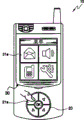
Fig. 1 is the diagrammatic sketch that shows the mancarried device that has rotatable load button according to an exemplary embodiment of the present invention;
Fig. 2 A, 2B and 2C show that rotation has the diagrammatic sketch of the example of the rotatable load button group that is provided with in the mancarried device of rotatable load button according to an exemplary embodiment of the present invention;
Fig. 3 is the in-built block diagram that shows the mancarried device that has rotatable load button according to an exemplary embodiment of the present invention;
Fig. 4 is the in-built block diagram that shows the mancarried device with rotatable load button of another exemplary embodiment according to the present invention;
Fig. 5 A and 5B show the diagrammatic sketch of expecting the example of object according to the operation selection in response to being included in the load button in the mancarried device with rotatable load button of another exemplary embodiment of the present invention;
Fig. 6 A and 6B show according to the operation in response to the load button that is provided with in having the mancarried device of rotatable load button of another exemplary embodiment of the present invention to amplify and the diagrammatic sketch of the example of the expectation object that dwindles;
Fig. 7 A and 7B show the diagrammatic sketch that the example of the 3 d menu layer that provides is provided according to the operation in response to the load button that is provided with of another exemplary embodiment of the present invention in having the mancarried device of rotatable load button;
Fig. 8 is the process flow diagram that shows the method for operating rotatable load button according to an exemplary embodiment of the present invention; With
Fig. 9 is the process flow diagram that shows the method for the 3 d menu layer that exemplary operation provides according to the present invention.
Embodiment
Detailed description of carrying out and exemplary embodiment in conjunction with the drawings, various aspects of the present invention and characteristics will become clearer.Yet, the invention is not restricted to disclosed exemplary embodiment, but can accomplished in various ways.It is of the present invention open to provide exemplary embodiment to finish, and allows those of ordinary skill in the art to understand aspect of the present invention.The present invention only is defined by the following claims.Same numeral is used to represent same or similar part in whole accompanying drawing.
Hereinafter, describe exemplary embodiment of the present with reference to the accompanying drawings in detail.
Fig. 1 is the diagrammatic sketch that shows the mancarried device 10 that has rotatable load button according to an exemplary embodiment of the present invention.
As shown in Figure 1, mancarried device 10 comprises load button group 20, display panel 30 and control module (not shown).
That is to say that when not rotating load button group 20, the pattern of mancarried device 10 is set to basic model, wherein, moving hand (not shown) on the direction that is load button 21 settings.When rotation load button group 20, the pattern of mancarried device 10 is set to input pattern, in this pattern, can operate and the corresponding object in the position of load button 21.
For example, under the situation of basic model, the user can come the object 31 that provides on the mobile display panel 30 by moving hand on the direction that is provided with for load button 21, and selects desired object 31.
In addition, under the situation of input pattern, the user can directly select and the corresponding object of arranging 31 in the position of load button 21, perhaps amplifies and the image of reduced objects 31.
Hereinafter, provide the description of the operation of the mancarried device 10 in the input pattern with reference to Fig. 2 A, 2B and 2C.
For example, when detecting the rotation of load button 21, the corresponding object 31 in position of the load button 21 of activation and demonstration and rotation.
Be elected to when selecting a time the load button of hoping 21, control module is carried out the operational order of expecting object 31 with the position of the load button of selecting 21 accordingly.
Fig. 2 A, 2B and 2C are the diagrammatic sketch that shows the example that is rotated in the rotatable load button group that is provided with in the mancarried device that has rotatable load button according to an exemplary embodiment of the present invention.
Shown in Fig. 2 A, when load button group 20 when predetermined direction (best but inessential, by 45 ° angle) rotates, load button 21 rotates by predetermined angular with load button group 20.In this case, form that can the first, second, third and the 4th quadrant is represented the load button 21 that rotates.
Shown in Fig. 2 B, represent load button 21a, the 21b, 21c and the 21d that rotate with the form of the first, second, third and the 4th quadrant, object 31a, the 31b, 31c and the 31d that are presented on the display panel 30 are arranged corresponding with the first, second, third and the 4th quadrant of load button.
As shown in the figure, the load button of selecting to expect as the user (for example, in the time of 21a), activates and the expectation object (for example 31a) of operation and the corresponding arrangement of the load button of selecting (for example 21a).
Shown in Fig. 2 C, represent the load button that rotates with the form of the first, second, third and the 4th quadrant, object 31a, the 31b, 31c and the 31d that are presented on the display panel 30 are arranged corresponding with the first, second, third and the 4th quadrant of load button.In this case, suppose to show to as if image file.
In addition, (for example, in the time of 21a), (for example, image 31a) is exaggerated the load button of selecting to expect as the user with the corresponding expectation object of arranging of the load button of selecting (for example 21a).(for example, in the time of 21a), (for example, image 31a) is shown on the whole screen that covers display panel 30 same object when the user repeats to select identical load button.
Fig. 3 is the internal frame diagram that shows the mancarried device that has rotatable load button according to an exemplary embodiment of the present invention.
As shown in Figure 3, mancarried device comprises: signal input unit 110, load button rotation detecting circuit 120, UI generation unit 130, mode setting unit 140, position detection unit 150, display unit 160 and control module 180.
Load button rotation detecting circuit 120 detects the user by the rotation that detects load button 21 and whether rotates load button 21, and when detecting the rotation of load button 21, will detect rotation and be notified to control module 180.
When detecting the rotation of load button 21 by load button rotation detecting circuit 120, mode setting unit 140 changes into the present mode of mancarried device to object 31 that provides and the pattern of operating with the corresponding desired object in the position of the load button of selecting 21 are provided on display panel 30.The pattern of mancarried device 10 is classified as one of basic model and input pattern.Basic model is set when not rotating load button 21.In this pattern, pointer can move on the direction of motion that is each load button 21 settings.Input pattern is set when rotation load button 21.Under this pattern, can operate being arranged in and the corresponding locational object 31 in the position of load button 21.
When detecting the rotation of load button 21 by load button rotation detecting circuit 120, the new position of the load button 21 that changes by rotation is checked in position detection unit 150.
For example, when load button 21 that the user selects to expect, determine to be positioned at and the load button 21 corresponding locational objects of selecting 31 based on the position of the change of the load button of checking by position detection unit 150 21.As the result who determines, the corresponding locational object 31 in position of the load button 21 that activates and select, and operate on it.
Display unit 160 shows object 31 and the menu layer 35 that produces by UI generation unit 130.In addition, display unit 160 shows the object 31 according to user's selection activation.
The term of Shi Yonging " unit " (can " module ", " table " etc.) is meant component software and nextport hardware component NextPort in the present embodiment, such as field programmable gate array (FPGA) or special IC (ASIC).Module can be used for carrying out various functions.Yet this is not meant that module is limited to software or hardware.Module can be configured to be present in addressable storage medium, and can be configured on one or more processing units and carry out.For example, module can comprise assembly, such as component software, OO component software, class component and task component, process, function, attribute, program, subroutine, program code segments, driver, firmware, microcode, circuit, data, database, data structure, table, array and parameter.The function that in assembly and module, provides can with the assembly and the module combinations of lesser amt, perhaps can be separated into additional assembly and module.In addition, can realize that assembly and module are to carry out on the one or more CPU in device.
Fig. 4 is the in-built block diagram that shows the mancarried device with rotatable load button 10 of another exemplary embodiment according to the present invention.
As shown in Figure 4, mancarried device 10 comprises: signal input unit 110, load button rotation detecting circuit 120, UI generation unit 130, mode setting unit 140, position detection unit 150, display unit 160, determining unit 170 and control module 180.The signal input unit 110 of mancarried device 10, load button rotation detecting circuit 120, UI generation unit 130, position detection unit 150, display unit 160 and control module 180 are carried out and identical function as described in Figure 3, and increase and implemented the function of mode setting unit 140 and determining unit 170 in this exemplary embodiment.Therefore, here only description scheme the function of unit 140 and determining unit 170 is set.
Determining unit 170 determines that the position of the load button 21 of the rotation that position detection unit 150 is checked is the primary importance or the second place.Primary importance is meant the original position of the load button 21 before load button 21 rotations, and the second place is meant the load button 21 rotations position of the change of load button 21 afterwards.
As the definite result in the determining unit 170, if determine that the position of load button 21 is primary importances, then mode setting unit 140 is provided with the basic model of selecting desired object 31.If determine that the position of load button 21 is second places, then mode setting unit 140 is arranged on the input pattern that moves between the menu layer 35.
For example, when load button 21 did not rotate, load button 21 was arranged in primary importance, and two-dimensional menu layer 35 is presented on the display panel 30.
When load button 21 rotations, the position change of load button 21 is to the second place, and 3 d menu layer 35 is presented on the display panel 30.Therefore, the user can move between the menu layer 35 that shows, and uses the load button 21 of expectation to select one of menu layer 35 that shows.
Fig. 5 A and 5B be show another exemplary embodiment according to the present invention select the diagrammatic sketch of the example of desired object in response to the operation that is included in the load button in the mancarried device with rotatable load button.
Shown in Fig. 5 A, the menu layer 35 with a plurality of objects 31 is presented on the display panel 30, and has the not rotation of load button group 20 of a plurality of load buttons 21.
Shown in Fig. 5 B, when the user rotated load button group 20, load button 21 also rotated, therefore, the position change of load button 21, and the pattern of mancarried device is changed and is provided with.
When the pattern of mancarried device 10 is changed into input pattern from basic model, and when the pattern of mancarried device 10 is set, be presented on the display panel 30 with the object of the corresponding predetermined quantity of arranging in position of load button 21.That is to say, the load button 21 of rotation is arranged in the first, second, third and the 4th quadrant, and the object 31 that is presented on the display panel 30 is arranged arrangement with corresponding with the first, second, third and the 4th quadrant of load button 21 with 2 * 2.
The load button of selecting to expect as the user (for example, in the time of 21a), activate and the corresponding object in position of operation and the load button 21 of selection (for example, 31a).
Fig. 6 A and 6B be show another exemplary embodiment according to the present invention amplify and dwindle the diagrammatic sketch of the example of desired object in response to the operation of the load button that in having the mancarried device of rotatable load button, is provided with.
As shown in Figure 6A, comprise that the menu layer 35 of a plurality of objects 31 is presented on the display panel 30, and the load button group 20 with a plurality of load buttons 21 is not rotated.
Shown in Fig. 6 B, when the user rotated load button group 20, load button 21 also rotated, therefore, the position change of load button 21, and the pattern of mancarried device changes.
The pattern of mancarried device 10 is changed into input pattern from basic model, and when the pattern of change is set, and is presented on the display panel 30 with the object 31 of the corresponding predetermined quantity of arranging in position of load button 21.
The load button of selecting to expect as the user ((for example, in the time of 21a), amplifies and shows the corresponding object in position (for example, image 31a) with the load button 21a of selection.
Fig. 7 A and 7B are the diagrammatic sketch that the example of the 3 d menu layer that provides is provided in the operation in response to the load button that is provided with in having the mancarried device of rotatable load button of demonstration another exemplary embodiment according to the present invention.
Shown in Fig. 7 A, comprise that menu layer 35 two dimensions of a plurality of objects 31 are presented on the display panel 30, and have the not rotation of load button group 20 of a plurality of load buttons 21.
Shown in Fig. 7 B, when the user rotates load button group 20, load button 21 rotations, therefore, the position change of load button 21 is the second place, and the pattern of mancarried device also changes.
When the pattern of mancarried device 10 is changed into input pattern from basic model, 3 d menu layer 35a, 35b and 35c are presented on the display panel 30.
Thereafter, (for example, in the time of 21b), the user can move between the 3 d menu layer 35a, the 35b that show and 35c the load button of selecting to expect as the user.
Specifically, when selecting load button (for example, in the time of 21b), to select the on-screen menu layer (for example, 35b), and it is shown as goes up menu layer most.In addition, (for example, in the time of 21b), the menu layer that selects a sound (for example, 35C), and is shown as it and goes up menu layer most when the user selects load button once more.
Simultaneously, (for example, 35a) during alternative, the user is primary importance by rotation load button group 20 with the position change of load button 21, and also changes the pattern of mancarried device from the superiors of 3 d menu layer 35a, 35b and 35c when user expectation.Thereafter, the user is based upon the direction that moves that each load button 21 is provided with focus is moved to selecteed object.
Fig. 8 is the process flow diagram that shows the method for the rotatable load button of operation of another exemplary embodiment according to the present invention.
At first, at step S800, load button rotation detecting circuit 120 detects the user and whether has rotated load button group 20.In this case, when rotating load button group 20, also rotate load button 21.
As the result who detects, if determine to have rotated load button 21, then at step S810, mode setting unit 140 is changed into input pattern with the pattern of mancarried device 10, and input pattern is set.In this case, pattern that can mancarried device 10 is set to basic model and input pattern.When not rotating load button 21, basic model is set, and pointer moves on the direction that moves that is each load button 21 settings.When rotation load button 21, input pattern is set, and can operates and the corresponding object 31 in the position of load button 21.
Thereafter, when the pattern that changes mancarried device 10 and when its pattern is set, at step S820, position detection unit 150 checks because the position of the load button 21 of the change that the rotation of load button group 20 causes.
Thereafter, UI generation unit 130 produces the UI of the input pattern that is suitable for being provided with, and by display unit 160 UI that produces is presented on the display panel 30.That is to say that at step S830, it is presented at the object 31 with corresponding position of arranging, the position of load button 21 (for example, arranging with 2 * 2).
When at step S840, during load button 21 that the user selects to expect, signal input unit 110 receives the button signal that produces, and sends it to control module 180.
Simultaneously, when the object 31 that is being presented on the display panel 30 is under the situation of image, when the user selected load button 21, the image that is positioned at the object 31 of the corresponding position, position of the load button of selecting 21 was exaggerated (or dwindling).
Therefore, when the object 31 that provides on the display panel 30 was provided user expectation, the user can rotate load button group 20 and select and the corresponding load button 21 in the position of selecteed object 31 is activated the operation of corresponding object at predetermined direction.Therefore, the user can select and operate desired object more quickly and easily.
Fig. 9 is the process flow diagram of the method for the 3 d menu layer that shows that the operation of another exemplary embodiment according to the present invention provides.
At first, at step S900, load button rotation detecting circuit 120 detects the user and whether has rotated load button group 20.In this case, when rotation load button group 20, also rotate load button 21.
As result as detection load button group 20, when determining load button 21 rotations, position detection unit 150 checks because the position (S910) of the load button 21 of the change that the rotation of load button group 20 causes, and determining unit 170 determines that the position of the load buttons 21 checked is the primary importance or the second place.
If at step S920, as the result who determines, the position of determining load button 21 is the second place, and then at step S930, mode setting unit 140 is changed into input pattern with the pattern of mancarried device 10, and input pattern is set.In this case, the pattern of mancarried device 10 can be set to basic model and input pattern.When not rotating load button 21, basic model is set, and pointer can move on the direction that moves that is each load button 21 settings.When rotation load button 21, input pattern is set, and can operates the 3 d menu layer 35 that is presented on the display panel 30.
Thereafter, when the pattern of mancarried device 10 was changed into input pattern and input pattern is set, UI generation unit 130 produced 3 d menu layer 35, and at step S940, by display unit 160 the 3 d menu layer 35 that produces was presented on the display panel 30.
Thereafter, when at step S950, during load button 21 that the user selects to expect, signal input unit 110 receives the button signal that produces, and sends it to control module 180.
Thereafter, when load button 21 that the user selects to expect, control module 180 is carried out control, thereby moves between step S960 is with the menu layer of focus in 3-D display.
Simultaneously, after the user has selected the menu layer 35 of expectation, when user expectation when the menu layer 35 of expectation is selected desired object 31, the user by rotation load button group 20 with the position change of load button 21 to primary importance.Therefore, the pattern of mancarried device is changed into basic model, and basic model is set.In this case, the user can change to focus the object 31 of the moving direction selection that is based upon each load button 21 settings.
As the result who determines, if determine that at step S920 the position of load button is a primary importance, then at step S970, mode setting unit 140 is changed into basic model with the pattern of mancarried device 10, and basic model is set.Thereafter, UI generation unit 130 produces two-dimensional menu layer 35, and by display unit 160 the two-dimensional menu layer 35 that produces is presented on the display panel 30.
Thereafter, when at step S980, during load button 21 that the user selects to expect, signal input unit 110 receives the button signal that produces, and this button signal is sent to control module 180.
Thereafter, when button that the user selects to expect, at step S990, control module 180 moves to focus and is based upon the object 31 that moving direction that each load button 21 is provided with is selected.
Therefore, the user can be only by selecting load button 21 to operate the menu layer 35 of 3-D display easily.
There are one or more following effects in the method for mancarried device with rotatable input buttons according to aspects of the present invention and operation mancarried device.
The advantage that exists is: can operate easily and the corresponding object of arranging in the position of the load button that rotates by the load button that predetermined angular is rotatably provided on the mancarried device.
In addition, the advantage of existence is: can be rotatably provided in the menu layer (or content of expectation) that load button on the mancarried device comes the three-dimensional on the operation display panel easily to provide by predetermined angular.
And the advantage of existence is: can use button to select and operate desired object and three dimensional object, need not the input media that provides independent.
Although, it should be appreciated by those skilled in the art, under situation about not breaking away from, can carry out various modifications, interpolation and replacement by the disclosed scope and spirit of the present invention of claim for disclosing of illustrative purpose exemplary embodiment of the present invention.
Claims (11)
1. mancarried device with rotatable load button comprises:
Button rotation detecting unit detects the rotation of load button;
The position detection unit, when detecting the rotation of load button, inspection is in response to the position of the load button of user's rotation change;
Mode setting unit, when detecting the rotation of load button, with the present mode of mancarried device change into to the pattern of the corresponding Object Operations in position of the load button of rotation; With
User interface UI generation unit produces the corresponding object in position with the load button that rotates.
2. mancarried device as claimed in claim 1, wherein, described to as if image, in response to the selection of load button, will amplify with the image of the corresponding object in position of the load button of selecting and dwindle.
3. mancarried device as claimed in claim 1 also comprises:
Display unit, the object that explicit user interface UI generation unit produces.
4. mancarried device with rotatable load button comprises:
Button rotation detecting unit detects the rotation of load button;
The position of the load button that changes according to described rotation when detecting the rotation of load button, is checked in the position detection unit;
Determining unit determines that the position of the load button that the rotation in response to load button changes is the primary importance or the second place; With
Mode setting unit, if the position of load button is a primary importance, then the present mode of mancarried device is changed into the pattern of selecting desired object and the pattern that change is set, if the position of load button is the second place, then the present mode of mancarried device is changed into pattern that execution moves and the pattern that change is set between the 3 d menu layer.
5. mancarried device as claimed in claim 4 also comprises:
Display shows object and 3 d menu layer corresponding to the primary importance generation of the load button that rotates.
6. mancarried device with rotatable load button comprises:
The load button group is rotated on the direction of expectation, and is had a plurality of load buttons;
Display panel when detecting the rotation of load button, shows the corresponding object in position with the load button that rotates; With
Control module is elected to when selecting a time the load button of hoping, to operating with the corresponding object in position of the load button of selecting.
7. mancarried device with rotatable load button comprises:
The load button group is rotated on the direction of expectation, and is had a plurality of load buttons;
Display panel when the rotation load button, shows 3 d menu layer and desired object; With
Control module is elected to when selecting a time the load button of hoping, is controlled between the 3 d menu layer and moves.
8. an operation has the method for the mancarried device of rotatable load button, and this method comprises:
Detect the rotation of load button;
When detecting the rotation of load button, the present mode of mancarried device is changed into input pattern, and the pattern of change is set, and determine the position of the load button that the rotation in response to load button changes;
When present mode is changed into input pattern, show the corresponding desired object in position with load button; With
Be elected to when selecting a time the load button of hoping, to operating with the corresponding object in position of the load button of selecting.
9. method as claimed in claim 8, wherein, when show to as if during image, in response to the selection of load button, be exaggerated with the image of the corresponding object in position of the load button of selecting and dwindle.
10. an operation has the method for the mancarried device of rotatable load button, and this method comprises:
Detect the rotation of load button;
When detecting the rotation of load button, determine the position of the load button that the rotation in response to load button changes;
As the result who determines,, then the present mode of mancarried device is changed into input pattern, and the pattern of change is set if determine that the position of load button is the second place;
When present mode is changed into input pattern, show the 3 d menu layer;
Be elected to when selecting a time the load button of hoping, from the 3 d menu layer that shows, select a menu layer.
11. method as claimed in claim 10 also comprises:
As the result who determines,, then the present mode of mancarried device is changed into basic model, and the pattern of change is set if determine that the position of load button is a primary importance; With
When present mode is changed into basic model, use load button from 3 d menu layer alternative, and operand.
Applications Claiming Priority (2)
| Application Number | Priority Date | Filing Date | Title |
|---|---|---|---|
| KR1020050132045 | 2005-12-28 | ||
| KR1020050132045A KR100678963B1 (en) | 2005-12-28 | 2005-12-28 | Portable device and operation method comprising input button to enable revolution |
Publications (2)
| Publication Number | Publication Date |
|---|---|
| CN1991711A CN1991711A (en) | 2007-07-04 |
| CN100462905C true CN100462905C (en) | 2009-02-18 |
Family
ID=37772582
Family Applications (1)
| Application Number | Title | Priority Date | Filing Date |
|---|---|---|---|
| CNB2006101682342A Expired - Fee Related CN100462905C (en) | 2005-12-28 | 2006-12-26 | Portable device having rotatable input buttons and method of operating the same |
Country Status (5)
| Country | Link |
|---|---|
| US (1) | US8042058B2 (en) |
| EP (1) | EP1804155B1 (en) |
| JP (1) | JP4559404B2 (en) |
| KR (1) | KR100678963B1 (en) |
| CN (1) | CN100462905C (en) |
Cited By (1)
| Publication number | Priority date | Publication date | Assignee | Title |
|---|---|---|---|---|
| US10510097B2 (en) | 2011-10-19 | 2019-12-17 | Firstface Co., Ltd. | Activating display and performing additional function in mobile terminal with one-time user input |
Families Citing this family (27)
| Publication number | Priority date | Publication date | Assignee | Title |
|---|---|---|---|---|
| KR100742730B1 (en) * | 2005-12-29 | 2007-07-25 | 엘지전자 주식회사 | method for executing menu of mobile phone and mobile phone thereof |
| DE102007021724B3 (en) * | 2007-05-09 | 2008-10-30 | Continental Automotive Gmbh | Arrangement of a keyboard with switchable control buttons for menu control in a motor vehicle |
| JP2009146668A (en) * | 2007-12-12 | 2009-07-02 | Canon Inc | Electronic device |
| CN101943988B (en) * | 2009-07-09 | 2013-04-24 | 深圳富泰宏精密工业有限公司 | System and method for automatically adjusting user interface of electronic device |
| KR20110118239A (en) * | 2010-04-23 | 2011-10-31 | 르노삼성자동차 주식회사 | Apparatus for controlling a car audio and method of playing the car audio using the same |
| KR20120017649A (en) * | 2010-08-19 | 2012-02-29 | 삼성전자주식회사 | Display apparatus and control method |
| KR101250420B1 (en) * | 2011-09-22 | 2013-04-05 | 성균관대학교산학협력단 | Input device for vehicle |
| US11513675B2 (en) | 2012-12-29 | 2022-11-29 | Apple Inc. | User interface for manipulating user interface objects |
| KR102117450B1 (en) * | 2013-03-26 | 2020-06-01 | 삼성전자주식회사 | Display device and method for controlling thereof |
| KR20190114034A (en) * | 2013-09-03 | 2019-10-08 | 애플 인크. | Crown input for a wearable electronic device |
| EP3822759A1 (en) | 2013-09-03 | 2021-05-19 | Apple Inc. | User interface for manipulating user interface objects |
| US11068128B2 (en) | 2013-09-03 | 2021-07-20 | Apple Inc. | User interface object manipulations in a user interface |
| US10545657B2 (en) | 2013-09-03 | 2020-01-28 | Apple Inc. | User interface for manipulating user interface objects |
| DE102014204321A1 (en) * | 2014-03-10 | 2015-09-10 | Ford Global Technologies, Llc | Switch for selecting and adjusting seat-related functions of motor vehicle seats |
| CN106462340B (en) | 2014-06-27 | 2019-09-13 | 苹果公司 | The user interface that size reduces |
| WO2016036416A1 (en) | 2014-09-02 | 2016-03-10 | Apple Inc. | Button functionality |
| CN112199000A (en) | 2014-09-02 | 2021-01-08 | 苹果公司 | Multi-dimensional object rearrangement |
| CN110072131A (en) | 2014-09-02 | 2019-07-30 | 苹果公司 | Music user interface |
| US10073590B2 (en) | 2014-09-02 | 2018-09-11 | Apple Inc. | Reduced size user interface |
| WO2016036509A1 (en) | 2014-09-02 | 2016-03-10 | Apple Inc. | Electronic mail user interface |
| USD800758S1 (en) | 2014-09-23 | 2017-10-24 | Seasonal Specialties, Llc | Computer display screen with graphical user interface for lighting |
| US10365807B2 (en) | 2015-03-02 | 2019-07-30 | Apple Inc. | Control of system zoom magnification using a rotatable input mechanism |
| DK201670595A1 (en) | 2016-06-11 | 2018-01-22 | Apple Inc | Configuring context-specific user interfaces |
| DK179888B1 (en) | 2018-09-11 | 2019-08-27 | Apple Inc. | CONTENT-BASED TACTICAL OUTPUTS |
| US11435830B2 (en) | 2018-09-11 | 2022-09-06 | Apple Inc. | Content-based tactile outputs |
| US11893212B2 (en) | 2021-06-06 | 2024-02-06 | Apple Inc. | User interfaces for managing application widgets |
| JP2023131553A (en) * | 2022-03-09 | 2023-09-22 | 本田技研工業株式会社 | vehicle |
Citations (4)
| Publication number | Priority date | Publication date | Assignee | Title |
|---|---|---|---|---|
| JPH11288346A (en) * | 1998-04-02 | 1999-10-19 | Toshiba Corp | Information display device |
| CN1274892A (en) * | 1999-05-20 | 2000-11-29 | 三星电子株式会社 | Computer system having user interface using rotary switch and method thereof |
| JP2001296953A (en) * | 2000-04-11 | 2001-10-26 | Sony Corp | Information input operation unit |
| CN1579085A (en) * | 2002-07-02 | 2005-02-09 | 索尼株式会社 | Portable information terminal, program, and recording medium having the program recorded therein |
Family Cites Families (19)
| Publication number | Priority date | Publication date | Assignee | Title |
|---|---|---|---|---|
| JP2000194492A (en) * | 1998-12-24 | 2000-07-14 | Matsushita Electric Ind Co Ltd | Image recording and reproducing device |
| DK1028570T3 (en) | 1999-02-11 | 2005-02-14 | Sony Int Europe Gmbh | Wireless telecommunications terminal and method for displaying icons on a display of such a terminal |
| US7750891B2 (en) * | 2003-04-09 | 2010-07-06 | Tegic Communications, Inc. | Selective input system based on tracking of motion parameters of an input device |
| US7286115B2 (en) * | 2000-05-26 | 2007-10-23 | Tegic Communications, Inc. | Directional input system with automatic correction |
| JP2001160933A (en) | 1999-12-01 | 2001-06-12 | Matsushita Electric Ind Co Ltd | Image display device |
| JP3903731B2 (en) * | 2000-08-03 | 2007-04-11 | 松下電器産業株式会社 | Multi-directional input device and electronic apparatus using the same |
| US6593914B1 (en) | 2000-10-31 | 2003-07-15 | Nokia Mobile Phones Ltd. | Keypads for electrical devices |
| JP2002091680A (en) | 2000-09-19 | 2002-03-29 | Matsushita Electric Ind Co Ltd | Switching device and portable terminal |
| JP2002341998A (en) | 2001-05-16 | 2002-11-29 | Casio Comput Co Ltd | Information processor and character input device |
| JP3820548B2 (en) | 2001-06-01 | 2006-09-13 | ソニー株式会社 | Information input device and electronic device using the same |
| US20030044000A1 (en) * | 2001-08-29 | 2003-03-06 | Kfoury Tony N. | Electronic device with rotatable keypad and display |
| US7046230B2 (en) * | 2001-10-22 | 2006-05-16 | Apple Computer, Inc. | Touch pad handheld device |
| US6670563B1 (en) * | 2002-12-03 | 2003-12-30 | Samsung Electronics Co., Ltd. | Rotation key device for a portable terminal |
| JP2004295355A (en) | 2003-03-26 | 2004-10-21 | Nec Corp | Portable radio terminal having multidirectional key switching function |
| JP2004326427A (en) | 2003-04-24 | 2004-11-18 | Mitsumi Electric Co Ltd | Input device for portable equipment |
| JP4356830B2 (en) * | 2003-08-28 | 2009-11-04 | ソニー株式会社 | Information processing apparatus, information processing method, storage medium storing information processing program, and information processing program |
| KR20050031758A (en) * | 2003-09-30 | 2005-04-06 | 엘지전자 주식회사 | Button apparatus of mobile phone |
| US7185818B2 (en) * | 2003-12-29 | 2007-03-06 | Symbol Technologies, Inc. | Rotatable/removeable keyboard |
| CN1985236B (en) | 2004-05-10 | 2010-06-23 | 松下电器产业株式会社 | User interface apparatus, program, and recording medium |
-
2005
- 2005-12-28 KR KR1020050132045A patent/KR100678963B1/en not_active IP Right Cessation
-
2006
- 2006-11-27 US US11/604,306 patent/US8042058B2/en not_active Expired - Fee Related
- 2006-12-13 EP EP06126009.7A patent/EP1804155B1/en not_active Expired - Fee Related
- 2006-12-20 JP JP2006342258A patent/JP4559404B2/en not_active Expired - Fee Related
- 2006-12-26 CN CNB2006101682342A patent/CN100462905C/en not_active Expired - Fee Related
Patent Citations (4)
| Publication number | Priority date | Publication date | Assignee | Title |
|---|---|---|---|---|
| JPH11288346A (en) * | 1998-04-02 | 1999-10-19 | Toshiba Corp | Information display device |
| CN1274892A (en) * | 1999-05-20 | 2000-11-29 | 三星电子株式会社 | Computer system having user interface using rotary switch and method thereof |
| JP2001296953A (en) * | 2000-04-11 | 2001-10-26 | Sony Corp | Information input operation unit |
| CN1579085A (en) * | 2002-07-02 | 2005-02-09 | 索尼株式会社 | Portable information terminal, program, and recording medium having the program recorded therein |
Cited By (3)
| Publication number | Priority date | Publication date | Assignee | Title |
|---|---|---|---|---|
| US10510097B2 (en) | 2011-10-19 | 2019-12-17 | Firstface Co., Ltd. | Activating display and performing additional function in mobile terminal with one-time user input |
| US10896442B2 (en) | 2011-10-19 | 2021-01-19 | Firstface Co., Ltd. | Activating display and performing additional function in mobile terminal with one-time user input |
| US11551263B2 (en) | 2011-10-19 | 2023-01-10 | Firstface Co., Ltd. | Activating display and performing additional function in mobile terminal with one-time user input |
Also Published As
| Publication number | Publication date |
|---|---|
| US8042058B2 (en) | 2011-10-18 |
| JP4559404B2 (en) | 2010-10-06 |
| KR100678963B1 (en) | 2007-02-06 |
| EP1804155B1 (en) | 2017-07-19 |
| EP1804155A2 (en) | 2007-07-04 |
| CN1991711A (en) | 2007-07-04 |
| JP2007179544A (en) | 2007-07-12 |
| EP1804155A3 (en) | 2012-08-22 |
| US20070146352A1 (en) | 2007-06-28 |
Similar Documents
| Publication | Publication Date | Title |
|---|---|---|
| CN100462905C (en) | Portable device having rotatable input buttons and method of operating the same | |
| JP5174372B2 (en) | Function icon display system and method | |
| JP4271702B2 (en) | 3D motion graphic user interface, apparatus and method for providing the same | |
| JP4271700B2 (en) | 3D graphic user interface, apparatus and method for providing the same | |
| US8059094B2 (en) | Apparatus and method for navigation in three-dimensional graphical user interface | |
| US8068094B2 (en) | Pointing device, information display device, and input method utilizing the pointing device | |
| JP3797977B2 (en) | Character input device, character input method, and character input program | |
| JP2007287135A (en) | Image display controller and program for image display controller | |
| WO2017169263A1 (en) | Display processing device and display processing program | |
| CN102402328A (en) | Information processing apparatus, program, and control method | |
| CN103197878A (en) | Information processing apparatus and information processing method | |
| JP5810513B2 (en) | Operation processing apparatus, operation processing method, and program therefor | |
| CN100543659C (en) | The navigator that is used for three-dimensional graphic user interface | |
| JP5830997B2 (en) | Information processing apparatus, information processing method, and program | |
| JP2000032110A (en) | Telephone set | |
| JP4803951B2 (en) | CHARACTER INPUT DEVICE, ITS PROCESSING METHOD, RECORDING MEDIUM, AND PROGRAM | |
| JPH11232026A (en) | Image processor | |
| JP2007156922A (en) | Process instruction receipt method, electronic apparatus, and computer program | |
| JP2004246599A (en) | The japanese syllabary input system and method | |
| JP5060651B2 (en) | Display processing apparatus, display control program, and display processing method | |
| JP5366381B2 (en) | Apparatus and method for providing menu object preview function | |
| KR100664927B1 (en) | Method and apparatus for menu navigation supporting usability | |
| KR101004764B1 (en) | Portable terminal provided with rotary push switch and method for selecting items using the same | |
| KR20100081200A (en) | Method for switching location of menu in user interface | |
| JP2002373054A (en) | Device and method for processing information, input device, recording medium, and program |
Legal Events
| Date | Code | Title | Description |
|---|---|---|---|
| C06 | Publication | ||
| PB01 | Publication | ||
| C10 | Entry into substantive examination | ||
| SE01 | Entry into force of request for substantive examination | ||
| C14 | Grant of patent or utility model | ||
| GR01 | Patent grant | ||
| C17 | Cessation of patent right | ||
| CF01 | Termination of patent right due to non-payment of annual fee |
Granted publication date: 20090218 Termination date: 20100126 |