CN100450427C - Determining relative positional and rotational offsets - Google Patents
Determining relative positional and rotational offsets Download PDFInfo
- Publication number
- CN100450427C CN100450427C CNB038036398A CN03803639A CN100450427C CN 100450427 C CN100450427 C CN 100450427C CN B038036398 A CNB038036398 A CN B038036398A CN 03803639 A CN03803639 A CN 03803639A CN 100450427 C CN100450427 C CN 100450427C
- Authority
- CN
- China
- Prior art keywords
- image
- imaging device
- hole
- labelling
- localizer
- Prior art date
- Legal status (The legal status is an assumption and is not a legal conclusion. Google has not performed a legal analysis and makes no representation as to the accuracy of the status listed.)
- Expired - Fee Related
Links
Images


Classifications
-
- A—HUMAN NECESSITIES
- A61—MEDICAL OR VETERINARY SCIENCE; HYGIENE
- A61B—DIAGNOSIS; SURGERY; IDENTIFICATION
- A61B3/00—Apparatus for testing the eyes; Instruments for examining the eyes
- A61B3/10—Objective types, i.e. instruments for examining the eyes independent of the patients' perceptions or reactions
- A61B3/1015—Objective types, i.e. instruments for examining the eyes independent of the patients' perceptions or reactions for wavefront analysis
-
- A—HUMAN NECESSITIES
- A61—MEDICAL OR VETERINARY SCIENCE; HYGIENE
- A61B—DIAGNOSIS; SURGERY; IDENTIFICATION
- A61B3/00—Apparatus for testing the eyes; Instruments for examining the eyes
- A61B3/10—Objective types, i.e. instruments for examining the eyes independent of the patients' perceptions or reactions
- A61B3/14—Arrangements specially adapted for eye photography
- A61B3/15—Arrangements specially adapted for eye photography with means for aligning, spacing or blocking spurious reflection ; with means for relaxing
- A61B3/152—Arrangements specially adapted for eye photography with means for aligning, spacing or blocking spurious reflection ; with means for relaxing for aligning
-
- G—PHYSICS
- G06—COMPUTING; CALCULATING OR COUNTING
- G06V—IMAGE OR VIDEO RECOGNITION OR UNDERSTANDING
- G06V40/00—Recognition of biometric, human-related or animal-related patterns in image or video data
- G06V40/10—Human or animal bodies, e.g. vehicle occupants or pedestrians; Body parts, e.g. hands
- G06V40/18—Eye characteristics, e.g. of the iris
- G06V40/19—Sensors therefor
Abstract
The present invention provides an apparatus and method for determining a relative positional and rotational offsets between a first and second imaging device. In exemplary embodiments, the present invention can be used to determine the relative offsets between a Hartmann-Shack wavefront sensor and a pupil camera. Calibration apparatus (12) includes a body (48) that may include openings (50) for receiving a calibration rail. A rotatable and translatable body (54) has a centered cross-shaped aperture (2) which is movable coupled to body (48).
Description
With reference to related application
Claim of the present invention the priority of temporary patent application 60/356658, the denomination of invention of this patent application is " equipment and the method that are used for determining the relative position between one first and second imaging device and rotate skew ", submit on February 11st, 2002, its whole inventions are incorporated into herein and are used as reference.
The invention still further relates to temporary patent application 60/356657, denomination of invention for " being used to calibrate the method and apparatus of an optical wavefront system; " and temporary patent application 60/356672 denomination of invention be " being used to excise the closed loop system and the method for lens " with aberration, these two patent applications are all submitted on February 11st, 2002, and its whole inventions are incorporated into herein and are used as reference.
Technical field
The present invention relates generally to one second imaging device and aims at one first imaging device.The invention particularly relates to the relative position between first and second imaging devices that are used for a definite wavefront system and rotate equipment and the method that is offset.
Background technology
Laser operated eye program adopts certain can measure the system of the optical characteristics of patient's eye usually.A kind of eye measurement system likely is VISX WaveScan
TMSystem, this system adopts a Hartmann-Shack wavefront sensing apparatus, and it can quantize the higher order aberratons of whole optical system, comprises single order and second order goalpost surface error, and three to the six rank aberrations that caused by intelligent shape and spherical aberration.The wavefront measurement of eyes produces a higher order aberratons figure, can estimate the aberration of the whole optical path of eyes by it, for example, and the aberration of inner aberration and anterior corneal surface.After this, wavefront aberration information can be saved, and is put into laser system then, so that calculate an excision model of proofreading and correct the customization of the aberration in patient's eye.
WaveScan
TMSystem also comprises a photographing unit (" pupil camera "), and it obtains the image of eyes when obtaining wavefront measurements with Hartmann-Shack wavefront sensing apparatus.The locus that the image of the eyes that obtain with pupil camera can be used for following the tracks of eyes, so as in the corneal ablation therapeutic process, will to excise laser correctly with eye alignment.
Owing in laser ablation process the tracking of eyes and aligning are based on the image that obtains with pupil camera, so (translation ground with rotatably) to aim at be very important on wave front data and the image space that pupil camera is obtained.If pupil camera and Wavefront sensor do not have to get on the space standard when obtaining wavefront measurements, the corneal ablation under laser helps of then ensuing dependence wavefront measurements, then may not with patient's eye alignment.
What therefore, need is to determine the relative position between two imaging devices of wavefront system and the equipment and the method for rotation skew.
Summary of the invention
The present invention measures Hartmann-Shack photographing unit and the relative position between the pupil camera and the rotation skew of wavefront system, and described two photographing units of calibration wavefront system.
The present invention's software algorithm that realizes that can use a computer is proofreaied and correct the position of Hartmann-Shack pick off and pupil camera and the error between the rotation, so that the image that obtains with two imaging devices can correctly be aimed at relative to each other.In case determined the position and the rotation skew of Hartmann-Shack pick off and pupil camera, side-play amount can be stored in the internal memory of system, so that the skew between the image that the software recoverable obtains with photographing unit.Usually, method of the present invention is used in the manufacture process of wavefront system or system before the periodic maintenance process lieutenant colonel quasi wave, so that guarantee that two imaging devices spatially are aligned in actual use.
But, will be appreciated that, though following explanation concentrates on the Hartmann-Shack pick off of a wavefront system and the spacial alignment of pupil camera, the present invention can be used for to any two (or a plurality of) simultaneously the imaging device of document image carry out aligning on the space.
In one aspect, the invention provides a calibrator (-ter) unit, be used for determining relative position and rotation skew between a Hartmann-Shack photographing unit and the pupil camera.This equipment comprises a main body with a hole.In some embodiments, hole is that rotation is asymmetric.Rotate asymmetric hole and can take multiple asymmetric form.In a useful embodiment, asymmetric hole is taked the form of cross or X.In some configuration, equipment can comprise the device of the main body reflection that is used to prevent the direct slave unit of light.In other configuration, hole can be connected on the main body movably, so that allow hole with respect to main body rotation and translation.Equipment can be positioned on the imaging plane of Hartmann-Shack photographing unit and pupil camera, so that it is by two photograph machine simultaneously imagings.The image of equipment can be used for measuring and compensating the position and the rotation skew of two photographing units.
In one aspect of the method, the invention provides and a kind of one first imaging device is aimed at or Calibration Method with one second imaging device.This method comprises substantially places an aligning equipment or localizer, so that localizer is by first imaging device and the second imaging device imaging.The image of the localizer that is obtained by first imaging device and second imaging device is analyzed, to determine the dislocation between first imaging device and second imaging device.
There is multiple localizer to can be used for method and system of the present invention, to measure and to proofread and correct the dislocation between first and second imaging devices.For example, in some embodiments, can use fixed, a uncontrollable calibrator (-ter) unit.The user in other embodiments, can use a complete adjustable calibrator (-ter) unit, so that can regulate a direction of rotation peace pan position of at least a portion of calibrator (-ter) unit.
In one embodiment, this method comprises provides a calibrator (-ter) unit or localizer, and it comprises a main body with the asymmetric hole of rotation.This localizer is placed on the optical path of first imaging device and second imaging device.The image of localizer is obtained by first imaging device and second imaging device.Bootable light arrives first imaging device and second imaging device by rotating asymmetric hole, and with first imaging device and second imaging device to the hole imaging, to determine position and rotation skew.First imaging device can be a Hartmann-Shack photographing unit of measuring wave front data.Hole also can be adjustable.
Labelling or cover layer can be added at least one image in the image of the localizer that first and second imaging devices obtain.Labelling in the image that obtains with first imaging device moves from a nominal position (for example, a center of image), so that labelling is fully alignd with localizer.The mobile message of the labelling in first image (for example, along the rotation of moving and center on the z axle of x axle and y axle) is saved, and is used for reference in the future.Labelling in the image that obtains with second imaging device moves from a nominal position (for example, a center of image), so that labelling is fully alignd with localizer.The mobile message of the labelling in second image also is saved, and is used for reference in the future.At last, relatively the mobile message of the labelling in first image and the mobile message of the labelling in second image are offset to determine rotation and position between first and second imaging devices.
In another embodiment, localizer can be by first imaging device and the second imaging device imaging.Translation position of scalable localizer and direction of rotation are arranged in the position of wanting of image that is obtained by first imaging device, for example image center up to localizer.In case localizer is positioned at the position of wanting, then analyze the image that obtains by second imaging device, whether be positioned at the identical position of wanting (for example a, center of the image that obtains by second imaging device) to determine localizer.If localizer is not positioned at the position of wanting, then a labelling that covers on the image that is obtained by second imaging device can move from the position of wanting, and fully aligns with localizer up to it.The mobile message of labelling can be used for determining that rotation and position between first and second imaging devices are offset then.
In aspect also having one, the invention provides a system, this system comprises an imaging system, and this imaging system has a Hartman-Shack photographing unit and a pupil camera.A calibrator (-ter) unit, for example a main body that comprises an asymmetric hole of rotation can be positioned on the optical path of Hartmann-Shack photographing unit and pupil camera.A control system is connected to Hartmann-Shack photographing unit and pupil camera, to determine the relative position of calibrator (-ter) unit in the image that each photographing unit obtains, so that determine the skew between two photographing units.
In one embodiment, control system has first and second patterns.Control system in first pattern can be configured to that a labelling is superimposed upon image of the calibrator (-ter) unit that obtained by the Hartmann-Shack photographing unit and an image obtaining by pupil camera on nominal position.Can allow labelling to move to the image of asymmetric hole fully aligns.In second pattern, control system can be compared the mobile type of the labelling in the mobile type of the labelling in the image that is obtained by the Hartmann-Shack photographing unit and the image that is obtained by pupil camera, so that determine position and rotation skew between Hartmann-Shack photographing unit and the pupil camera.
In one aspect of the method, the invention provides code module and graphical user interface, be used to realize the method for the present invention that illustrates herein.
These and other aspect will show in appendix, explanation and the claim of remainder.
Description of drawings
Fig. 1 has schematically described a wavefront system, calibrator (-ter) unit and object of being realized by the present invention.
Fig. 2 has schematically described the wavefront system of a simplification of the present invention.
Fig. 3 has schematically described the computer system of a simplification of the present invention.
Fig. 4 has described the certain module that can realize method of the present invention.
Fig. 5 has shown an embodiment that combines a calibrator (-ter) unit of the present invention.
Fig. 6 has schematically described the method for a simplification of the present invention of the calibrator (-ter) unit that uses Fig. 5.
Fig. 7 has shown an image of the calibrator (-ter) unit of the Fig. 5 that is obtained by a pupil camera.
Fig. 8 has shown an image of the calibrator (-ter) unit of the Fig. 5 that is obtained by a Hartmann-Shack photographing unit.
Fig. 9 has shown an amended Hartmann-Shack image of the calibrator (-ter) unit of Fig. 5.
Figure 10 has shown another embodiment that combines a calibrator (-ter) unit of the present invention.
Figure 11 has schematically described the method for a simplification of the present invention of the calibrator (-ter) unit that uses Figure 10; And
Figure 12 to 17 has described some graphical user interface of the present invention of the method for the present invention of the calibrator (-ter) unit that can be used for realizing using Figure 10.
The specific embodiment
The present invention is particularly useful for the accuracy and the effect that strengthen laser operated eye program (for example laser photorefractive keratectomy (PRK), Light therapy keratectomy (PTK), the auxiliary anterior lamellar keratectomy (LASIK) of laser etc.).The present invention preferably can be used to obtain and aims at the method for a corneal ablation or the light degree of accuracy that other dioptric treatment procedure to patient's eye strengthens the dioptric program by improvement.
Though system and method for the present invention mainly is to be illustrated under the situation of a laser operated eye system, but should be appreciated that technology of the present invention can be used for other eye treatment program and system, for example radial keratectomy, the crystalline thing of ophthalmic, corneal ring are implanted, collagen cornea tissue thermogravimetric is moulded etc.
Fig. 1 has schematically described a calibration system 10 of the present invention.Calibration system 10 comprises a Reference, for example is held in place localizer or calibrator (-ter) unit 12 in the optical path 14 of the wavefront system 16 between wavefront system 16 and the object 18.Except that other parts, wavefront system 16 also can comprise a Hartmann-Shack photographing unit and a pupil camera, is used for obtaining respectively simultaneously wave front data and image of eyes.
Light can send from a light source (not shown) of wavefront system 16, and a hole 20 through in the calibrator (-ter) unit 12 is mapped on the object 18 then.Object 18 can be used for producing a point source of Hartmann-Shack photographing unit and pupil camera.A branch of generation or reverse light can be penetrated by the hole 20 of calibrator (-ter) unit 12 from object 18 and get back to the wavefront system 16.Because calibrator (-ter) unit 12 is placed in the plane of delineation of Hartmann-Shack photographing unit, therefore a speckle patterns corresponding to the shape of the hole in the calibrator (-ter) unit 12 20 appears in the image that is obtained by the Hartmann-Shack photographing unit.In one embodiment, hole 20 is that rotation is asymmetric.If necessary, hole can be rotational symmetric but in another embodiment.The position of definite calibrator (-ter) unit 12 and direction are to estimate the skew between the photographing unit in two images.
In a configuration, object 18 can have rough white surface, so that reduce the amount of undesired luminous reflectance.In another configuration, object 18 comprises
 It can be with the light of diffusion on the catoptrics back, by calibrator (-ter) unit 12.But, should be realized that, can use multiple other material as object, so that toward back reflective or generation light, by calibrator (-ter)
 unit 12.
Fig. 2 has schematically described the wavefront system 16 of a simplification of the present invention.Wavefront system 16 comprises a Hartmann-Shack photographing unit 22 substantially, and it is configured to obtain a wavefront measurements of the optical texture of patient's eye.Hartmann-Shack photographing unit 22 has a lens arra (not shown), and this An arrayed recording is in the skew of retina glazed thread from a point source.Wavefront system 16 also comprises a pupil camera 24, CCD for example, and it is configured to an image of record patient eyes when the Hartmann-Shack photographing unit carries out wavefront measurement.A controller, for example a computer system 26 can be connected to photographing unit 22,24, is used to analyze and calibrate the image that is obtained by photographing unit 22,24.Computer system 26 can be combined in the wavefront system 16, and perhaps it can be an independent computer that is connected to photographing unit 22,24.
Fig. 3 is the block diagram of a simplification of a computer system 26, and this computer system can be used for the image according to an embodiment of the invention are aimed at and alignment is obtained by photographing unit 22,24.Computer system 26 comprises at least one processor 28, and it is communicated by letter with a plurality of ancillary equipment by a bus sub 30.These ancillary equipment can comprise a storage subsystem 32, and it comprises a memory subsystem 34 and a file storage subsystem 36, user interface input equipment 38, user interface outut device 40, and an optional network interface subsystem 42.Input and output device makes that the user can be mutual with computer system 26.User can be a human user, equipment, process, another computer etc.
User interface input equipment 38 can comprise a keyboard, pointing device (for example mouse, tracking ball, touch pad or a drawing board), a scanner, a barcode scanner, an input equipment that is combined in touch screen, audio input device (for example speech recognition system, mike) and other type in the display.Usually, use " input equipment " this phrase to be intended to comprise the method for all possible equipment of the system's of using a computer 26 input informations.
User interface outut device 40 can comprise the display of a display subsystem, a printer, a facsimile machine or non-vision, for example audio output apparatus.Display subsystem can be a cathode ray tube (CRT), a planar device (a for example liquid crystal display (LCD)), perhaps a projector equipment.Usually, use " outut device " this phrase is intended to comprise all possible equipment and the method from computer system 26 output informations.
Fig. 4 has described the block diagram of a simplification of the certain module of realizing method of the present invention.These modules can realize in the combination of the software in the wavefront system 16, hardware or software and hardware.In embodiment shown in Figure 4, module 80 comprises a Subscriber Interface Module SIM 82, image module 84, image processing module 86 and a calibration module 88.
Subscriber Interface Module SIM 82 provides an interface, but by user's input command of this interface, the result that checks image and check calibration.But user's input command is handled image, to help to determine the direction of rotation and the position of the calibrator (-ter) unit in the image that Hartmann-Shack photographing unit 22 and pupil camera 24 obtain.
According to an embodiment of the invention, the image of calibration module is obtained from photographing unit 22,24 by image module 84.Image can be stored among the data base 90, and this data base can be arranged in a storage subsystem 32, a remote server is medium.Which image the user can show by providing suitable input to specify in Subscriber Interface Module SIM 82.In case suitable image is revealed, then image processing module 86 is configured to receive input command by Subscriber Interface Module SIM 82, handling the image that obtains from one of photographing unit, so that determine the image parameter (for example, the direction of calibrator (-ter) unit and position skew) of the image that obtains by photographing unit.In case analyzed after first image by image processing module 86, then the image and the parameter information of first image can be stored among the data base 90.Available subscribers interface module 82 access images modules 84 then are to check second image (for example, the image that is obtained by another photographing unit).The user can analyze and obtain the image parameter of second image by Subscriber Interface Module SIM 82 indicating image processing modules 86 then, and second image and image parameter are stored among the data base 90.
In case analyzed after two images by image processing module 86, then available calibration module 88 visits are stored in the information among the data base 90, with the skew between the image of determining to be obtained by photographing unit 22,24.Calibration module 88 can be configured to the calibration result of calibration is outputed to Subscriber Interface Module SIM 82, selectively, also can automatically the result be kept among the data base 90 and calculating skew automatically.The result of calibration also can only output to Subscriber Interface Module SIM 82.The user can indicate calibration module 88 that calibration result is kept among the data base 90 then.As can being realized, data base 90 can be visited by other module (can be that local module also can be a far module), so that calibration information can be used in wavefront system and/or the laser surgery system, with any skew between the compensation photographing unit 22,24.
The present invention alignment image also is provided and compensate first imaging device (for example the Hartmann-Shack photographing unit 22) and second imaging device (for example pupil camera 24) between the ad hoc approach of dislocation.If (X
P, Y
P) be the pixel coordinate of pupil camera 24, and (X
HS, Y
HS) be the pixel coordinate of Hartmann-Shack photographing unit 22, a projective transformation that relates to two coordinate systems of Hartmann-Shack photographing unit 22 and pupil camera 24 is then arranged.Find a rigid transformation, be enough to describe two relations between the photographing unit.Thereby this rigid transformation can be described by three parameter Δ x, Δ y and θ, and wherein Δ x is that translation, Δ y along X-axis are the translations along Y-axis, and θ is the rotation around the Z axle.Scale factor " A " between Hartmann-Shack photographing unit 22 and the pupil camera 24 is a known fixed value.Then this is for conversion into:
For determining the value of transformation parameter Δ x, Δ y and θ, localizer or calibrator (-ter) unit 12 can be by Hartmann-Shack photographing unit 22 and pupil camera 24 imagings, position and direction with the equipment in the image of determining two photographing units, so that can determine the spatial deviation of photographing unit, so that estimate transformation parameter subsequently.
Fig. 5 has described one and has combined calibrator (-ter) unit 12 of the present invention.Calibrator (-ter) unit 12 can be positioned over a WaveScan regularly
TMOn the alignment rail (not shown), so that calibrator (-ter) unit 12 is placed on the optical axis 14 of wavefront system 16 (Fig. 1).But, will be appreciated that multiple other conventional fixture can be used for calibrator (-ter) unit is placed on WaveScan
TMSystem or other are for example by Bausch﹠amp; In the plane of delineation of the wavefront system that Lomb, Alcon Labs and Wavefront Sciences make or sell.A hole is positioned at the center of the main body 48 of calibrator (-ter) unit 12, so that light can come from object 18 (Fig. 1) reflection, and gets back in Hartmann-Shack photographing unit 22 and the pupil camera 24 by hole.Hole 20 can be configured to width W on two dimension all corresponding to the twice of the spacing of the lens of the lens arra of Hartmann-Shack photographing unit.
In exemplary embodiment, hole 20 is that rotation is asymmetric, and it is shaped as cross, and pore width is about 1mm.Cross is a first-selected embodiment, so it has clearly center origin (for example, the cross point between horizontal hole and the vertical hole).But should be realized that in other embodiments, hole can be the asymmetric shape of any rotation, for example line, trefoil shape, triangle, polygon have the circle of labelling etc., and can have other sizes.If desired, calibrator (-ter) unit 12 can comprise a plurality of openings 50, to receive the alignment rail (not shown).
As selection, calibrator (-ter) unit 12 also can comprise antireflection device 50, is used to prevent or reduces light directly from the reflection of the main body of calibrator (-ter) unit 12.In described embodiment, a middle body 52 of calibrator (-ter) unit is covered by a non-reflective materials, is perhaps made by a non-reflective materials, goes forward side by side into optical axis 14 from calibrator (-ter) unit 12 reflections so that prevent light.At an embodiment, the part of the diameter 8mm of piece central authorities has been coated with a kind of model railway engine black die with antireflection.Should be realized that, in some embodiments, can only calibrator (-ter) unit 12 be placed on the angle with respect to optical axis 14, so that prevent directly 16 optical axis 14 reflections of light from calibrator (-ter) unit along wavefront system.
Fig. 6 has schematically described a method for simplifying of the present invention that uses the calibrator (-ter) unit of Fig. 5.At first, in step 70, obtain the image of calibrator (-ter) unit, in step 72, determine the direction of rotation and the position of the calibrator (-ter) unit in the image that the Hartmann-Shack photographing unit obtains with Hartmann-Shack photographing unit and pupil camera.In step 74, determine the direction of rotation and the position of the calibrator (-ter) unit in the image that pupil camera is obtained.The position of the calibrator (-ter) unit in the image and rotation parameter and compared to each other to determine any rotation and translational offsets.In step 76, the comparative result of data can be used for the dislocation between definite photographing unit, and alignment image and calibration Hartmann-Shack photographing unit and pupil camera.In case determined the skew of rotation and position, then can generate a software correcting algorithm, to proofread and correct the dislocation between the photographing unit.
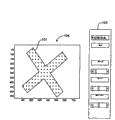
Fig. 7 to 9 has described the graphic user interface of some simplification that the calibrator (-ter) unit of Fig. 5 uses and the image that is obtained by Hartmann-Shack photographing unit 22 and pupil camera 24.For example Fig. 7 has described an image of the calibrator (-ter) unit 12 that is obtained by pupil camera 24.A computer system 26 (Fig. 2 and 3) go up the calibration software of communicate by letter of operation with photographing unit 22,24 can a nominal position at the image of hole 20 in labelling of interpolation or covering, for example red cross image 100 (perhaps corresponding to other images of the shape of hole 20).In a configuration, nominal position is the center of image.In described embodiment, the slider bar on user interface 102 is regulated and is made that the user can be along the mobile red cross image 100 of three parameters (Δ x, Δ y and θ), so that red cross image 100 is fully aimed at the image of hole 20.In said embodiment, position adjustments can be finished by the step-length of 1 pixel, and rotation is regulated and can be finished by the step-length of 1/2 degree.As shown in the slider bar adjusting, in this example, red cross image 100 has moved 27 pixels with respect to its original nominal position in the x direction, has moved 3 pixels in the y direction, and-6.0 ° of degree have been rotated, so that cover graphics 100 is fully aimed at asymmetric hole 20.These are from the value of slider bar, Δ x
Pupil->Object, Δ y
Pupil->ObjectAnd θ
Pupil->ObjectBe stored in the internal memory of computer system 26, so that reference in the future.But, should be realized that, except slider bar is regulated, can use multiple other software approachs with the image alignment of red cross image 100 with hole 20.In addition, except the image alignment with cover graphics and hole 20 manually, software module of the present invention can be configured to automatically cover graphics be alignd with hole 20.
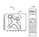
Fig. 8 has shown an image of the calibrator (-ter) unit 12 that Hartmann-Shack photographing unit 22 obtains.As known in the art, will be the form of a speckle patterns 104 from the image of a Hartmann-Shack photographing unit.For ease of reference, image has been limited in peaked more than 10%, so that raising is from the contrast of the speckle of the lens arra of Hartmann-Shack pick off.Similar to pupil camera, calibration software can add a labelling or cover graphics, for example a red cross image 101 or other images in the nominal position on the image that Hartmann-Shack photographing unit 22 obtains.User interface 103 can provide the slider bar of three parameters (Δ x, Δ y and θ) to regulate, and makes the user red cross image of cover graphics fully can be aimed at the spot image of asymmetric hole.As shown in the slider bar adjusting, in this example, red cross image 101 has moved-21 pixels in the x direction, has moved-7 pixels in the y direction, and has rotated 7.5 ° of degree, so that Red Cross 101 is aimed at the spot pattern image 104 of hole.In a configuration, position adjustments can be finished by the step-length of 1 pixel, and rotation is regulated and can be finished by the step-length of 1/2 degree.Usually, red cross image 101 should be placed as and make it cover the speckle of the image of hole 20 as much as possible.It or not institute's spottiness that in all configurations, all may cover the Hartmann-Shack image.From the value of slider bar, Δ x
HS->Object, Δ y
HS->ObjectAnd θ
HS->ObjectBe stored in the internal memory of system, so that reference in the future.
Next procedure in the calibration process is the transformation parameter of setting up between two photographing units 22,24.This can be by realizing the reference of the relative position of an exterior object (for example, the hole of calibrating installation 12) as two photographing units.Therefore:
Δx=Δx
Pupil->Object-Δx
HS->Object
Δy=Δy
Pupil->Object-Δy
HS->Object
θ=θ
Pupil->Object-θ
HS->Object
Above transformation parameter can be placed in the above-mentioned transformation equation, to determine rotation relatively and position skew, so that the enough software of the present invention's energy be proofreaied and correct residual alignment error, so that the image that wavefront system can be obtained wavefront image and pupil camera accurately mates.
Thereby, according to above example:
Δ x=27 pixel-(21) pixel=48 pixels
Δ y=3 pixel-(7) pixel=10 pixels
θ=-6.0 degree-(7.5) degree=1.5 degree
Therefore, for the wavefront front view that Hartmann-Shack photographing unit 22 is obtained is spatially aimed at the image that pupil camera 24 is obtained, software must (for example move 48 pixels in+x direction with wave front chart, to the right), (for example move 10 pixels in+y direction, upwards), and around z axle rotation 1.5 spend (for example, counterclockwise).
Though because the visible edge of hole, make that cross image 100 is orientable with aiming at of hole image in the pupil image, image from the Hartmann-Shack photographing unit comprises one by the visible speckle patterns 104 of hole, but the row in the edge of speckle or the outside may not be clearly as seen.Thereby,, be stored in a image processing algorithm in the internal memory of computer system 26 and can be used for image from the Hartmann-Shack photographing unit in order to simplify with cross image 101 alignment procedures with the Hartmann-Shack image of hole 20.In such embodiment, as shown in Figure 9, can by shorten one of hole arm length revise the cross aperture of calibrator (-ter) unit 12 so that on cross aperture 20 main shaft 106 of definition and a countershaft 108.
For example, algorithm of the present invention can provide the step of a setting threshold, wherein is at least pixel value of being designated as 1 of 20% of highest brightness value in the image.Remaining value value of being designated as 0.It is that the square forming core of 40x40 carries out convolution that piece convolution step comprises 1 size with remaining image and one.This step can expand to speckle bigger piece, so that " speckle " (being bigger piece now) is merged together.At last, algorithm can comprise a morphological operation step, and wherein the remainder of binary picture is analyzed to find out barycenter and main shaft.In one embodiment, this operating procedure can realize with " imfeature " order of Matlab.From then on the value obtained of step can be used for the image of the hole 20 after red cross image 101 and the change is aligned.
Figure 10-17 has described other embodiments of a calibrator (-ter) unit, and the use of calibrator (-ter) unit.Figure 10 has described an adjustable embodiment of calibrator (-ter) unit 12, and it comprises a main body 48, and this main body 48 can comprise one or more optional openings 50, is used to receive alignment rail.Main body 54 with rotatable and translation of a cross hole 20 that is positioned at the center is connected to main body 48 movably.Calibrator (-ter) unit 12 can comprise the combination of rotation adjusting parts 56 and two member of translational 58,60, can carry out the rotation and the position adjustments of hole respectively by them.Pointed as arrow 62, start rotation adjusting parts 56 and make hole 20 around its center rotation.Start member of translational 58 and can make hole translation on the direction of arrow 64, can make hole 20 translation on the direction of arrow 66 and start member of translational 60.In one embodiment, member of translational the 58, the 60th, screw is so that rotary screw can cause moving of member of translational 58,60 and main body 54.
Figure 11 has schematically described the method for a simplification of the present invention of the adjustable calibration apparatus of using Figure 11.At first, in step 61, hole is placed as the center that is positioned at lens, so that it approaches the center of Hartmann-Shack spot image or the part that other are wanted most.Selectively, in step 63, cross aperture can continue be regulated, aims at the center of Hartmann-Shack image is approaching up to cross aperture, and the brightness of the Hartmann-Shack speckle in the row and column (or other parts of speckle patterns) balance more equably.In step 65, in case calibrator (-ter) unit is positioned at the center of Hartmann-Shack image, one with calibrator (-ter) unit in the labelling of hole with essentially identical shape move from center of image, and cover from the hole in the image of pupil camera.For the embodiment of Figure 10, the shape of labelling is a cross-hair, and it corresponds essentially to the shape of cross hole.In case labelling has been aimed at hole, in step 67, the required translation of the image of alignment mark and hole is moved and is rotated amount of movement, with the hope part of image in the hole distance H artmann-Shack image (for example, the center) any skew can be used for the dislocation between definite Hartmann-Shack photographing unit and the pupil camera together.
The present invention further provides the user interface that is used to realize method of the present invention.User interface helps the user to aim at the image of Hartmann-Shack photographing unit 22 and pupil camera 24.The user interface that is generated by the present invention can be stored in the storage subsystem, and output is on an outut device of wavefront system.Figure 12-17 has described multiple user interfaces of the present invention and the method for using the calibrator (-ter) unit of Figure 10.Have ordinary skill person and will recognize that other variations, modification and replacement can be used for the present invention.Therefore, below explanation is intended to describe, rather than limits the scope of the invention.
Figure 12 has described the user interface 110 that Hartmann-Shack photographing unit 22 and pupil camera 24 were calibrated and aimed in exemplary being used to.In said embodiment, user interface has a plurality of tabs 112, and they make the user can select the function of the software that moves on the computer.In order to calibrate Hartmann-Shack photographing unit and pupil camera, the user can select or open " service (service) " tabs 114 (for example, clicking this tabs with a pointer or arrow)." service " tabs window makes the user can select multiple different image parameter, as described by the menu that shows a sub-tabs 116 in the bottom near the interface.For align cameras 22,24, the user can select " camera alignment " tabs 118.
If desired, the user can activate large buttons 142, so that the whole middle body of any one the occupied user interface 110 in the image window 122,124.Can in real time, statically or time-delay is arranged check each image window 122,124.
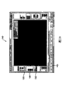
In order to begin to aim at and registration image, the user can activate " opening covering (overlay on) " button 132, so that will show the alignment member that covers on window displayed.In described embodiment, for Hartmann-Shack image window 122, alignment member comprises one first and second cross-hair 134,136.First cross-hair 134 is fixed, can be used for the part of any hope of the center of marking image or image.If software can be determined the center of Hartmann-Shack speckle patterns, then second cross-hair 136 also can be revealed, to describe the center of the speckle patterns of estimating.In one embodiment, showing cross-hair 134 and cross-hair 136 with different color (for example, yellow and blue) and/or different sizes comes so that cross-hair is distinguished from each other.Selectively, if software determines that the Hartmann-Shack image is not positioned at center or image and has rotated with respect to the center of image window, then can on image, show a prompting arrow 138.
Under the situation of pupil image window 124, a cover graphics 140 can comprise a cross corresponding to the shape of the hole in the calibrator (-ter) unit.In some pattern, the user can manual mobile cover graphics 140 and is reset its size.In other patterns, the position of cover graphics 140 and big I are determined automatically by software.
Now, can pass through to start large buttons 142 enlarged image windows 122 (Figure 12) referring to Figure 13 to 14.For improving picture quality, the user can regulate the contrast and the brightness of image by the brightness and contrast that input in input 144 is wished.For example, a useful configuration is that gray scale is about 50, and contrast level is about 100.As can recognizing,, can select other brightness and contrast of other levels according to the specific image that obtains.In case selected the brightness and contrast, the user can press the Next button 146.
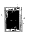
In a specific user, in user interface 147, the user can at first press " automatic focus (Auto-Focus) " button 148 and come focusedimage.If software can obtain the Hartmann-Shack image, results set can be presented in the text box 150,150 ', and whether indicating image is fully aimed at.In one embodiment, text box can be coupled with color, so that indicate whether to have realized aligning visually.For example, but red and/or prompting arrow 138 indicating images are not aligned (Figure 13) as yet, and green (and/or not pointing out arrow) but the aligning of indicating image is acceptable (Figure 14).If frame 150,150 ' indicating image are aimed at (for example, green does not have prompting arrow 138 etc. in the image), the user can be by advancing to next user interface by the Next button 146.
If frame 150,150 ' indicating image misalignment, then the user can be manually or is regulated the direction and the position of calibrator (-ter) unit automatically, so that the image-based of hole originally is positioned at the central authorities of speckle patterns, so that image is vertical and horizontal symmetry.As shown in figure 13, if software can be analyzed speckle patterns, then point out arrow 138 to be presented at the upper left of image window, so which direction indication user calibrator (-ter) unit must be regulated to, so that the center of hole 136 is fully aimed at the center of Hartmann-Shack image 134 (for example, on/down, a left side/right side and/or rotation), so that the center of the center of Hartmann-Shack image and hole (for example, cross-hair 134,136) is fully aimed at.
As frame 150,150, shown in, frame 150 is vertical stackings, and has shown the numeric results corresponding to the mean flow rate of three central row of speckle.The frame 150 that level is piled up is corresponding to the mean flow rate of three central serieses of speckle.The position of user's adjustable calibration apparatus and direction are up to the brightness of the row and column in outside balance more equably.As shown in figure 14, in interface 149, when the centrally aligned of the Hartmann-Shack of hole image and image, and the brightness of the row in the outside is more equably during balance, and first and last numeral in each frame 150,150 ' should be fully equal.As can recognizing, if desired, the user can specify a little calculating difference by tolerance of input in " tolerance (Tolerance) " control input 152, so that do not require that numeral is equal fully.As what can see in Figure 14, in " pattern shift (pattern the ofst) " frame in the lower left corner of user interface, lens arra center (for example, picture centre) calculated automatically with respect to the translation and the angular deflection at the center of the hole of calibrator (-ter) unit.
In case the pattern on the Hartmann-Shack image window 122 is aimed at fully, then the user can press the Next button 146, and it makes software switch to pupil camera image 124 and show this image on user interface 154.In one embodiment, software can be configured to attempt automatically the vertical and horizontal hole part in location.An xanchromatic cover graphics 140 will be indicated the position of the definite hole 20 of software.As an alternative, the user also can manually use in the right panel control 128 relative nominal position (for example, a center of image) position, angular direction and the width of adjusting cross-hair cover graphics 140 are so that be placed on cover graphics 140 on the image of hole.Software can calculate with respect to the translation of nominal position and rotation skew.In case the user determines cover graphics and is suitably placed, then the user can press the Next button 146, so that advance to user interface shown in Figure 16 156, here software will calculate position and the angular variation between Hartmann-Shack photographing unit and the pupil camera, as mentioned above.
Provide information to the analysis of image about the skew at the range image center of two photographing units.Because the absolute position of hole is identical (for example, to the imaging simultaneously of a hole) under two situations, so software can be determined the relative x of Hartmann-Shack photographing unit with respect to pupil camera, y and θ coordinate.Because analyzing is from selecting a specific Hartmann-Shack speckle as its center, and be the center with this speckle with hole, therefore software is also known the absolute position of Hartmann-Shack pattern, and pattern is with respect to the angle rotation of Hartmann-Shack photographing unit.
As can be seen in Figure 15 and 16, the numerical data in " position and rotation " frame 157 have been indicated the relative position and the angle rotation of the cover graphics in the coordinate of pupil camera, so that indication is with respect to the pixel and the differential seat angle of pupil camera picture centre.For the alignment parameter between the photographing unit 22,24 is set, the user can press " aligning is set " button 158, and it starts the calculating about the skew between the photographing unit 22,24, as mentioned above.In case supress " aligning is set " 158 buttons, software calculates the skew between the photographing unit 22,24 according to the method described above, and advances to user interface 160 (Figure 17), calibration here finishes.Selectively, the translation of two photographing units and angular variation also can be presented in " result " frame 164 of user interface.If desired, the user can be by next " printing " button 162 to obtain a hard copy of calibration.In described embodiment, offset data can be presented in " result " part on the lower right side of user interface.
Draw as those art technology practician will appreciate that, the present invention can implement with other particular forms under the situation that does not deviate from its fundamental characteristics.For example, the specific setting of graphic user interface is an example, should in no way limit the present invention.In addition, though method can illustrate a specific order analyzing Hartmann-Shack image and pupil camera image, also can carry out any analysis sequence, and the invention is not restricted to a specific analysis sequence.Above example only is to describe to combine some embodiment of the present invention, does not limit the scope of the invention.Have ordinary skill person and will recognize other variations, modification and replacement.Therefore, above stated specification does not limit the scope of illustrating in following claims of the present invention with explaining usefulness.
Claims (22)
1. be used to measure rotation between one first imaging device and one second imaging device and a kind of method of position skew, this method comprises:
Obtain first image of localizer and second image that second imaging device obtains localizer with first imaging device, wherein said first imaging device comprises a Hartmann-Shack photographing unit;
First labelling is added in first nominal position on first image of the described localizer that obtains with first imaging device;
Second labelling is added in second nominal position on second image of the described localizer that obtains with second imaging device;
Described first nominal position of first labelling from described first image that obtains with first imaging device moved to an aligned substantially position of the image with the hole of described localizer;
Described second nominal position of second labelling from described second image that obtains with second imaging device moved to an aligned substantially position of the described image with the described hole of described localizer;
The mobile message of the labelling in the mobile message of the labelling in first image and second image is compared to determine rotation and the position skew between first and second imaging devices.
2. the process of claim 1 wherein mobile message comprise translation along the x axle, along the translation of y axle and in the rotation of z axle one of at least.
3. the process of claim 1 wherein that the hole of localizer is that rotation is asymmetric.
4. the method for claim 3, wherein the shape of labelling corresponds essentially to the shape of the asymmetric hole of rotation of localizer.
5. the process of claim 1 wherein that the nominal position in the image is the center of image.
6. system comprises:
An imaging system, this system comprise a Hartmann-Shack photographing unit and a pupil camera;
A calibrator (-ter) unit, this equipment comprise a hole, and this hole is placed on the public optical path of optical path of the optical path of Hartmann-Shack photographing unit and pupil camera; And
A control system that is connected to imaging system, wherein control system is configured to have first pattern and second pattern, the control system that wherein is in first pattern is added a labelling to a image that the described hole by described calibrator (-ter) unit uses the Hartmann-Shack photographing unit to obtain, on the nominal position of the image that adds the described hole that obtains with pupil camera to, and allowing labelling to move to the image of described hole aims at substantially
Wherein the labelling in the image that will obtain with the Hartmann-Shack photographing unit of the control system in second pattern move with the image that obtains with pupil camera in labelling mobile phase relatively so that determine position and rotation skew between Hartmann-Shack photographing unit and the pupil camera.
7. the system of claim 6, its mesopore is that rotation is asymmetric.
8. the system of claim 6, wherein said hole comprises asymmetric hole, described asymmetric hole is criss-cross approx.
9. the system of claim 6, wherein imaging system is a wavefront system.
10. the system of claim 6, wherein localizer comprises a unreflecting middle body, to prevent reflection.
11. the system of claim 6 comprises an object on the optical axis that is positioned at imaging system, wherein calibrator (-ter) unit is between object and imaging system.
12. be used for determining first imaging device of a system and a kind of method of relative position between second imaging device and rotation skew, this method comprises:
A main body is provided, and this main body comprises the asymmetric hole of rotation of public optical path of the optical path of an optical path that is arranged in first imaging device and second imaging device;
Guiding light is mapped to first imaging device and second imaging device by rotating asymmetric hole;
To the hole imaging, the image that described first imaging device obtains comprises the speckle patterns corresponding to the shape of the asymmetric hole of described rotation with first imaging device and second imaging device; And
The relatively rotation and the position skew of the image of the image of the hole that obtains of first imaging device and the hole that second imaging device obtains is to determine relative position and the rotation skew between first and second imaging devices.
13. comprising, the method for claim 12, wherein said guiding make of the plane of reflection reflection of described light from an object.
14. the method for claim 12 wherein relatively comprises:
A labelling is added on the image that is obtained by first imaging device, and wherein labelling corresponds essentially to the shape of hole;
A nominal position on the image that described labelling on the image that first imaging device is obtained obtains from this first imaging device moves to hole aims at substantially;
Calculate on the image that first imaging device obtains described labelling along x axle, y axle move and around the rotation of z axle;
A labelling is added on the image that is obtained by second imaging device, and wherein labelling corresponds essentially to the shape of hole;
A nominal position on the image that described labelling on the image that second imaging device is obtained obtains from this second imaging device moves to hole aims at substantially;
Calculate on the image that second imaging device obtains described labelling along x axle, y axle move and around the rotation of z axle;
Labelling in the image that is obtained by first imaging device that calculates mobile deducted moving of labelling in the image that is obtained by second imaging device.
15. be used for one first imaging device and one the second aligned a kind of method of imaging device, described first imaging device comprises a Hartmann-Shack photographing unit, this method comprises:
Place a localizer, so that this localizer is by first imaging device and the second imaging device imaging, described localizer comprises a main body, and described main body comprises a hole, and the image that described first imaging device obtains comprises the speckle patterns corresponding to the shape of described hole; And
The image of the localizer that analysis is obtained by first imaging device and second imaging device is to determine the dislocation between first imaging device and second imaging device.
16. the method for claim 15 comprises the position of regulating localizer, so that localizer is arranged in the center of the image that is obtained by first imaging device.
17. the method for claim 16, wherein adjusting position is included at least one in the angular direction peace pan position that changes localizer in the optical axis of first imaging device.
18. the method for claim 17, wherein analysis image comprises translation and the angular variation of compute location device with respect to the center of the image that is obtained by second imaging device.
19. the method for claim 18, wherein calculating comprises:
A labelling is moved from the center of the image that obtained by second imaging device, aim at substantially with localizer up to labelling; And
Measurement is aimed at required translation substantially with labelling and localizer and is moved and the angle amount of movement.
20. the method for claim 15 comprises, the position of adjustment apertures and at least one in the angular direction, the basic uniform balance of brightness in the part of choosing of speckle patterns.
21. the method for claim 15, the shape of its mesopore is asymmetric, and wherein the hole of the asymmetric shape of localizer and described labelling comprise essentially identical shape.
22. the method for claim 21, the hole that shape is wherein arranged is criss-cross.
Applications Claiming Priority (2)
| Application Number | Priority Date | Filing Date | Title |
|---|---|---|---|
| US35665802P | 2002-02-11 | 2002-02-11 | |
| US60/356,658 | 2002-02-11 |
Publications (2)
| Publication Number | Publication Date |
|---|---|
| CN1630487A CN1630487A (en) | 2005-06-22 |
| CN100450427C true CN100450427C (en) | 2009-01-14 |
Family
ID=27734666
Family Applications (1)
| Application Number | Title | Priority Date | Filing Date |
|---|---|---|---|
| CNB038036398A Expired - Fee Related CN100450427C (en) | 2002-02-11 | 2003-02-11 | Determining relative positional and rotational offsets |
Country Status (9)
| Country | Link |
|---|---|
| US (1) | US7040759B2 (en) |
| EP (1) | EP1480550B1 (en) |
| JP (1) | JP4471661B2 (en) |
| CN (1) | CN100450427C (en) |
| AT (1) | ATE521276T1 (en) |
| AU (1) | AU2003219740A1 (en) |
| CA (1) | CA2475896C (en) |
| MX (1) | MXPA04007577A (en) |
| WO (1) | WO2003068058A1 (en) |
Families Citing this family (39)
| Publication number | Priority date | Publication date | Assignee | Title |
|---|---|---|---|---|
| US7355695B2 (en) | 2003-04-09 | 2008-04-08 | Amo Manufacturing Usa, Llc | Wavefront calibration analyzer and methods |
| US7338164B2 (en) | 2003-07-31 | 2008-03-04 | Visx, Incorporated | Systems and methods for eye aberration and image sensor orientation |
| IL157877A0 (en) * | 2003-09-11 | 2004-03-28 | Imagine It S Happening Ltd | Color edge based 3d scanner |
| US6873924B1 (en) * | 2003-09-30 | 2005-03-29 | General Electric Company | Method and system for calibrating relative fields of view of multiple cameras |
| JP2005118465A (en) * | 2003-10-20 | 2005-05-12 | Canon Inc | Ophthalmologic photographing device and photographing method |
| EP1682927B1 (en) * | 2003-11-10 | 2017-12-27 | AMO Manufacturing USA, LLC | Methods and devices for testing torsional alignment between a diagnostic device and a laser refractive system |
| JP4233439B2 (en) * | 2003-11-28 | 2009-03-04 | 株式会社ニデック | Ophthalmic equipment |
| US7130034B2 (en) * | 2004-04-26 | 2006-10-31 | The Boeing Company | Metrology system and method for measuring five degrees-of-freedom for a point target |
| US8597282B2 (en) * | 2005-01-13 | 2013-12-03 | Amo Manufacturing Usa, Llc | Database system for centralized clinical and research applications with data from wavefront aberrometers |
| JP4591211B2 (en) * | 2005-05-31 | 2010-12-01 | 富士ゼロックス株式会社 | Image processing apparatus, image processing method, medium, code reading apparatus, and program |
| JP4824400B2 (en) * | 2005-12-28 | 2011-11-30 | 株式会社トプコン | Ophthalmic equipment |
| TWI346795B (en) * | 2006-06-29 | 2011-08-11 | Himax Display Inc | Image inspecting device and method for a head-mounted display |
| US20090234692A1 (en) * | 2008-03-13 | 2009-09-17 | Tigo Energy, Inc. | Method and System for Configuring Solar Energy Systems |
| AU2009231687B2 (en) | 2008-04-01 | 2014-10-30 | Amo Development, Llc | Ophthalmic laser apparatus, system, and method with high resolution imaging |
| AU2009231779B2 (en) | 2008-04-01 | 2015-01-15 | Amo Development, Llc | System and method of iris-pupil contrast enhancement |
| US8622951B2 (en) | 2008-06-09 | 2014-01-07 | Abbott Medical Optics Inc. | Controlling a phacoemulsification system based on real-time analysis of image data |
| ATE509568T1 (en) * | 2008-10-22 | 2011-06-15 | Sensomotoric Instr Ges Fuer Innovative Sensorik Mbh | METHOD AND DEVICE FOR IMAGE PROCESSING FOR COMPUTER-ASSISTED EYE OPERATIONS |
| CN101639382B (en) * | 2009-08-25 | 2010-09-29 | 中国科学院光电技术研究所 | Method of using spherical wave front for absolute calibration of Hartmann-Shack sensor |
| TWI426775B (en) * | 2010-12-17 | 2014-02-11 | Ind Tech Res Inst | Camera recalibration system and the method thereof |
| US20120242839A1 (en) * | 2011-03-25 | 2012-09-27 | Tk Holdings Inc. | Image sensor calibration system and method |
| US9091614B2 (en) * | 2011-05-20 | 2015-07-28 | Canon Kabushiki Kaisha | Wavefront optical measuring apparatus |
| US8885882B1 (en) | 2011-07-14 | 2014-11-11 | The Research Foundation For The State University Of New York | Real time eye tracking for human computer interaction |
| US9182289B2 (en) * | 2011-10-14 | 2015-11-10 | Canon Kabushiki Kaisha | Apparatus and method for estimating wavefront parameters |
| CN105530854B (en) * | 2013-09-24 | 2018-01-12 | 视乐有限公司 | Change in response to eyes adjusts laser treatment |
| US20150157197A1 (en) * | 2013-12-09 | 2015-06-11 | Omer Aslam Ilahi | Endoscopic image overlay |
| CN106031081B (en) * | 2014-02-14 | 2019-07-19 | 诺基亚技术有限公司 | A kind of method, apparatus of encryption key distribution, mobile device and computer readable storage medium |
| ES2842183T3 (en) * | 2015-08-10 | 2021-07-13 | Fusmobile Inc | Image Guided Focused Ultrasound Treatment Device and Aiming Device |
| US9924160B1 (en) * | 2016-09-22 | 2018-03-20 | Fluke Corporation | Imaging device with alignment analysis |
| CN107179049A (en) * | 2017-05-27 | 2017-09-19 | 中国科学院上海技术物理研究所 | The optical measuring device and method of a kind of high-precision shafting running accuracy |
| CN107644183B (en) * | 2017-09-01 | 2020-10-23 | 福建联迪商用设备有限公司 | Decoding method and terminal of one-dimensional code CMOS camera engine |
| JP6962769B2 (en) * | 2017-09-28 | 2021-11-05 | 株式会社トプコン | Ophthalmic equipment |
| JP7090446B2 (en) * | 2018-03-22 | 2022-06-24 | 株式会社キーエンス | Image processing equipment |
| CN108510545B (en) * | 2018-03-30 | 2021-03-23 | 京东方科技集团股份有限公司 | Space positioning method, space positioning apparatus, space positioning system, and computer-readable storage medium |
| KR102268094B1 (en) * | 2019-03-09 | 2021-06-22 | 코어포토닉스 리미티드 | System and method for dynamic stereoscopic calibration |
| US20220358792A1 (en) * | 2019-08-09 | 2022-11-10 | Nec Corporation | Information processing system, information processing method, and storage medium |
| EP4037543A1 (en) * | 2019-09-30 | 2022-08-10 | Alcon Inc. | Improved ocular aberrometer systems and methods |
| WO2021159519A1 (en) | 2020-02-14 | 2021-08-19 | 西安大医集团股份有限公司 | Image guidance method and apparatus, radiotherapy device, and computer storage medium |
| CN112097642B (en) * | 2020-09-17 | 2021-06-15 | 北京理工大学 | Three-dimensional cross hole position degree detection instrument and detection method |
| CN114964056B (en) * | 2022-05-05 | 2023-03-17 | 大连理工大学 | Self-calibration method for micro-assembly equipment |
Citations (4)
| Publication number | Priority date | Publication date | Assignee | Title |
|---|---|---|---|---|
| US3614238A (en) * | 1968-01-05 | 1971-10-19 | Itek Corp | Bright line reticle apparatus and optical alignment methods |
| US4672676A (en) * | 1983-12-28 | 1987-06-09 | International Business Machines Corp. | Method and apparatus for automatically aligning an object with respect to a reference pattern |
| US6175750B1 (en) * | 1999-03-19 | 2001-01-16 | Cytometrics, Inc. | System and method for calibrating a reflection imaging spectrophotometer |
| WO2001028476A1 (en) * | 1999-10-21 | 2001-04-26 | Technolas Gmbh Ophthalmologische Systeme | Iris recognition and tracking for optical treatment |
Family Cites Families (18)
| Publication number | Priority date | Publication date | Assignee | Title |
|---|---|---|---|---|
| US3600098A (en) * | 1969-12-29 | 1971-08-17 | Bausch & Lomb | Optical alignment method and apparatus |
| DE3331444A1 (en) * | 1982-09-03 | 1984-03-08 | Asahi Kogaku Kogyo K.K., Tokyo | FOCUS DETECTOR DEVICE |
| JPS59101129A (en) * | 1982-11-30 | 1984-06-11 | キヤノン株式会社 | Apparatus for positional alignment and preciseness judgementof ophthalimic machine |
| US4640619A (en) * | 1985-03-13 | 1987-02-03 | Gca Corporation | Microlithographic calibration scheme |
| US5016282A (en) * | 1988-07-14 | 1991-05-14 | Atr Communication Systems Research Laboratories | Eye tracking image pickup apparatus for separating noise from feature portions |
| JP2974383B2 (en) * | 1990-08-21 | 1999-11-10 | キヤノン株式会社 | Gaze detection device and device having gaze detection device |
| JPH0574684A (en) * | 1991-09-13 | 1993-03-26 | Nikon Corp | Positioning device |
| US5655030A (en) * | 1993-12-27 | 1997-08-05 | Uht Corporation | Method for detecting the center of target marks by image processing |
| US5648854A (en) * | 1995-04-19 | 1997-07-15 | Nikon Corporation | Alignment system with large area search for wafer edge and global marks |
| US5960125A (en) * | 1996-11-21 | 1999-09-28 | Cognex Corporation | Nonfeedback-based machine vision method for determining a calibration relationship between a camera and a moveable object |
| US6396961B1 (en) * | 1997-11-12 | 2002-05-28 | Sarnoff Corporation | Method and apparatus for fixating a camera on a target point using image alignment |
| JP3763958B2 (en) * | 1998-01-20 | 2006-04-05 | 株式会社ニデック | Ophthalmic equipment |
| US6152563A (en) * | 1998-02-20 | 2000-11-28 | Hutchinson; Thomas E. | Eye gaze direction tracker |
| FR2777374B1 (en) * | 1998-04-10 | 2000-05-12 | Commissariat Energie Atomique | METHOD OF RECORDING TWO DIFFERENT IMAGES OF THE SAME OBJECT |
| US6215532B1 (en) * | 1998-07-27 | 2001-04-10 | Mixed Reality Systems Laboratory Inc. | Image observing apparatus for observing outside information superposed with a display image |
| US6199986B1 (en) * | 1999-10-21 | 2001-03-13 | University Of Rochester | Rapid, automatic measurement of the eye's wave aberration |
| WO2001033504A1 (en) * | 1999-10-29 | 2001-05-10 | Cognex Corporation | Method and apparatus for locating objects using universal alignment targets |
| US6637884B2 (en) * | 2001-12-14 | 2003-10-28 | Bausch & Lomb Incorporated | Aberrometer calibration |
-
2003
- 2003-02-11 JP JP2003567250A patent/JP4471661B2/en not_active Expired - Lifetime
- 2003-02-11 AT AT03716011T patent/ATE521276T1/en not_active IP Right Cessation
- 2003-02-11 MX MXPA04007577A patent/MXPA04007577A/en active IP Right Grant
- 2003-02-11 EP EP03716011A patent/EP1480550B1/en not_active Expired - Lifetime
- 2003-02-11 AU AU2003219740A patent/AU2003219740A1/en not_active Abandoned
- 2003-02-11 US US10/365,121 patent/US7040759B2/en not_active Expired - Lifetime
- 2003-02-11 WO PCT/US2003/004122 patent/WO2003068058A1/en active Application Filing
- 2003-02-11 CA CA2475896A patent/CA2475896C/en not_active Expired - Fee Related
- 2003-02-11 CN CNB038036398A patent/CN100450427C/en not_active Expired - Fee Related
Patent Citations (4)
| Publication number | Priority date | Publication date | Assignee | Title |
|---|---|---|---|---|
| US3614238A (en) * | 1968-01-05 | 1971-10-19 | Itek Corp | Bright line reticle apparatus and optical alignment methods |
| US4672676A (en) * | 1983-12-28 | 1987-06-09 | International Business Machines Corp. | Method and apparatus for automatically aligning an object with respect to a reference pattern |
| US6175750B1 (en) * | 1999-03-19 | 2001-01-16 | Cytometrics, Inc. | System and method for calibrating a reflection imaging spectrophotometer |
| WO2001028476A1 (en) * | 1999-10-21 | 2001-04-26 | Technolas Gmbh Ophthalmologische Systeme | Iris recognition and tracking for optical treatment |
Also Published As
| Publication number | Publication date |
|---|---|
| EP1480550A4 (en) | 2006-10-11 |
| US20030151720A1 (en) | 2003-08-14 |
| JP2005516716A (en) | 2005-06-09 |
| CA2475896C (en) | 2011-08-23 |
| US7040759B2 (en) | 2006-05-09 |
| AU2003219740A1 (en) | 2003-09-04 |
| WO2003068058A1 (en) | 2003-08-21 |
| JP4471661B2 (en) | 2010-06-02 |
| EP1480550B1 (en) | 2011-08-24 |
| CN1630487A (en) | 2005-06-22 |
| WO2003068058A9 (en) | 2004-06-03 |
| CA2475896A1 (en) | 2003-08-21 |
| ATE521276T1 (en) | 2011-09-15 |
| EP1480550A1 (en) | 2004-12-01 |
| MXPA04007577A (en) | 2004-11-10 |
Similar Documents
| Publication | Publication Date | Title |
|---|---|---|
| CN100450427C (en) | Determining relative positional and rotational offsets | |
| US20230419623A1 (en) | Systems for augmented reality visual aids and tools | |
| CN100442006C (en) | Tracking torsional eye orientation and position | |
| US7130447B2 (en) | Gaze tracking system, eye-tracking assembly and an associated method of calibration | |
| AU780951B2 (en) | Eye registration and astigmatism alignment control systems and method | |
| US7891811B2 (en) | System and method for axis identification in astigmatic cataract surgery | |
| CN110505459A (en) | Suitable for the image color correction method of endoscope, device and storage medium | |
| CN110321773A (en) | Use the neural metwork training for watching prediction attentively for three-dimensional (3D) of calibration parameter | |
| EP1385335A1 (en) | Image projector with image-feedback control | |
| CN102917635B (en) | Method for determining deviations between coordinate systems of various technical systems | |
| AU2014229610B2 (en) | Wavefront generation for ophthalmic applications | |
| US20040086270A1 (en) | Camera support device | |
| US5037194A (en) | Ophthalmologic apparatus and method of compounding the image of an eye to be examined | |
| CN110320999A (en) | Watch the deep learning of prediction attentively for three-dimensional (3D) | |
| CN111399633B (en) | Correction method for eyeball tracking application | |
| CN100482146C (en) | System for movement tracking of spherical object | |
| CN110320998A (en) | Training to the neural network for watching prediction attentively for three-dimensional (3D) | |
| US8591031B2 (en) | Device and method for determining the visual field | |
| CN109788279A (en) | A kind of linear light source and line-scan digital camera calibration method and device | |
| US20220076417A1 (en) | Vision screening systems and methods | |
| CN109997067A (en) | Use the display device and method of portable electronic device | |
| US20220187909A1 (en) | Light field vision testing device, adjusted pixel rendering method therefor, and vision testing system and method using same | |
| EP4230170A1 (en) | Portable three-dimensional image measuring device, three-dimensional image measuring method using same, and medical image matching system | |
| CN105989587A (en) | Automatic calibration method of multifunctional OCT (optical coherence tomography) system | |
| CN116035563B (en) | Photographic measurement system for abnormal head position |
Legal Events
| Date | Code | Title | Description |
|---|---|---|---|
| C06 | Publication | ||
| PB01 | Publication | ||
| C10 | Entry into substantive examination | ||
| SE01 | Entry into force of request for substantive examination | ||
| C14 | Grant of patent or utility model | ||
| GR01 | Patent grant | ||
| CF01 | Termination of patent right due to non-payment of annual fee | ||
| CF01 | Termination of patent right due to non-payment of annual fee |
Granted publication date: 20090114 Termination date: 20210211 |