CN100447036C - Body structure of automotive bicycle - Google Patents
Body structure of automotive bicycle Download PDFInfo
- Publication number
- CN100447036C CN100447036C CNB2006100716182A CN200610071618A CN100447036C CN 100447036 C CN100447036 C CN 100447036C CN B2006100716182 A CNB2006100716182 A CN B2006100716182A CN 200610071618 A CN200610071618 A CN 200610071618A CN 100447036 C CN100447036 C CN 100447036C
- Authority
- CN
- China
- Prior art keywords
- vehicle body
- handrail
- carrying element
- load
- seat
- Prior art date
- Legal status (The legal status is an assumption and is not a legal conclusion. Google has not performed a legal analysis and makes no representation as to the accuracy of the status listed.)
- Expired - Fee Related
Links
Images


Classifications
-
- B—PERFORMING OPERATIONS; TRANSPORTING
- B62—LAND VEHICLES FOR TRAVELLING OTHERWISE THAN ON RAILS
- B62K—CYCLES; CYCLE FRAMES; CYCLE STEERING DEVICES; RIDER-OPERATED TERMINAL CONTROLS SPECIALLY ADAPTED FOR CYCLES; CYCLE AXLE SUSPENSIONS; CYCLE SIDE-CARS, FORECARS, OR THE LIKE
- B62K11/00—Motorcycles, engine-assisted cycles or motor scooters with one or two wheels
- B62K11/02—Frames
-
- B—PERFORMING OPERATIONS; TRANSPORTING
- B62—LAND VEHICLES FOR TRAVELLING OTHERWISE THAN ON RAILS
- B62J—CYCLE SADDLES OR SEATS; AUXILIARY DEVICES OR ACCESSORIES SPECIALLY ADAPTED TO CYCLES AND NOT OTHERWISE PROVIDED FOR, e.g. ARTICLE CARRIERS OR CYCLE PROTECTORS
- B62J7/00—Luggage carriers
- B62J7/02—Luggage carriers characterised by the arrangement thereof on cycles
- B62J7/04—Luggage carriers characterised by the arrangement thereof on cycles arranged above or behind the rear wheel
-
- B—PERFORMING OPERATIONS; TRANSPORTING
- B62—LAND VEHICLES FOR TRAVELLING OTHERWISE THAN ON RAILS
- B62K—CYCLES; CYCLE FRAMES; CYCLE STEERING DEVICES; RIDER-OPERATED TERMINAL CONTROLS SPECIALLY ADAPTED FOR CYCLES; CYCLE AXLE SUSPENSIONS; CYCLE SIDE-CARS, FORECARS, OR THE LIKE
- B62K2202/00—Motorised scooters
Abstract
The present invention provides a vehicle body structure of a motorcycle capable of easily setting a side grip at the adequate height above a vehicle body without degrading the supporting rigidity of the side grip.A fuel tank cover 17 extends to a rear part of a storage box 8 arranged below an openable/closable seat. A side grip 23 for a rider to support a vehicle body from a lower side thereof with hands of the rider placed thereon is integrated with the fuel tank cover 17. A root part 32 side of the grab rail 31 expanding backward of the seat is fastened to a rear frame 7, and one end of a supporting member 35 is fastened to an upper portion of the root part 32. The other end of the supporting member 35 is fastened to the side grip 23 above the fastened part of the grab rail 31 to the rear frame 7 and at the inner position of the vehicle body.
Description
Technical field
The present invention relates to the body structure of automatic two-wheeled cycle, relate in particular in order when strutting support etc., to support vehicle body and to have the body structure of the automatic two-wheeled cycle of the sidepiece handle that hand is inserted for the rider by lower side.
Background technology
As the body construction of automatic two-wheeled cycle, following content has been proposed in patent documentation 1.
This body structure below the seat that can open and close, is provided with and accommodates case, accommodates the rear sidepiece rising wood of case at this, extends the Fuel Tank cover that is provided with the top that covers Fuel Tank integratedly, at the side edge part of this Fuel Tank cover, is provided with the sidepiece handle.In addition, on the rear portion of vehicle body vehicle frame (vehicle body frames), be supported with the Fuel Tank that covers by described Fuel Tank cover, and, near rearward end, be provided with upward outstanding boss (boss), with pillar that this boss combines on, be fastened with the hinder marginal part (rear end of sidepiece handle) and the baggage rack of described Fuel Tank cover jointly, on baggage rack, in conjunction with armed root.Also have, baggage rack be fastened on pillar below, the hinder marginal part of Fuel Tank cover is combined in the upper face side of pillar.
Therefore, in the body structure of this automatic two-wheeled cycle, if the rider holds the sidepiece handle and lifts vehicle body when strutting support etc., then via the joint portion of Fuel Tank cover to rear portion vehicle frame applied load.
[patent documentation 1] spy opens the 2004-182108 communique
But, in this existing body structure, baggage rack is combined in the following side of pillar that is incorporated into the rear portion vehicle frame of vehicle body via boss, on the other hand, the rear end of sidepiece handle is combined in the upper face side of pillar, therefore, if set the sidepiece handle on the suitable height of desiring when strutting support etc., to wish, then the curve that is used to insert finger of sidepiece handle must be offset greatly to the top of the Support Position of the sidepiece handle of pillar, in this case, increase the wall thickness of sidepiece handle or its periphery, or enhancing is used to guarantee the rigidity of support of sidepiece handle with muscle etc. mechanism is set separately.
Summary of the invention
Therefore, the invention provides the rigidity of support that effectively to guarantee the sidepiece handle, and the sidepiece handle easily can be set in the body structure of the automatic two-wheeled cycle of suitable height.
To achieve these goals, the present invention, (for example be by vehicle body frames, rear portion vehicle frame 7 in the embodiment described later) handrail of Zhi Chenging (grab rail) (for example, handrail 31 in the embodiment described later) outstandingly (for example is arranged on seat that the rider takes a seat, seat 10 in the embodiment described later) rear side, and sidepiece below described seat, be provided with and be used to make the rider that hand with the sidepiece handle that supports vehicle body from lower side (is for example inserted, sidepiece handle 23 in the embodiment described later), in the body structure of this automatic two-wheeled cycle, the root of described handrail is fastened on the vehicle body frames, and the upper face side of the root of this handrail install support described sidepiece handle load-carrying element (for example, load-carrying element 35 in the embodiment described later), with the thick edge portion of sidepiece handle be fastened on this load-carrying element to the outstanding end of vehicle body inside front, to utilize the Support Position of this support member support sidepiece handle, be set in the position that more relies on the top than the fastening position of handrail and vehicle body frames.
Under situation of the present invention, can the Support Position of the sidepiece handle of load-carrying element will be utilized, be set in the position that more relies on the top than the fastening position of handrail and vehicle body frames, therefore can the sidepiece handle be set in the position of the suitable height on the vehicle body not upward under the crooked significantly prerequisite of side.In addition, thus, can be omitted in reinforced rib required under the situation of the big macrobending of side upward or increase the reinforcement of wall thickness etc.
Be preferably, be set as and open and close at described seat, and below this seat, dispose in the automatic two-wheeled cycle of accommodating case, the described case of accommodating (for example is provided with rearward the Extendible flake that extends, Fuel Tank cover 17 in the embodiment described later), integral type forms described sidepiece handle on this Extendible flake.
In this case, sidepiece handle integral type is formed on the Extendible flake of accommodating case, thereby can reduce the parts number of packages, therefore can reduce manufacturing cost, and can improve assembleability.
In addition, also can constitute described load-carrying element, this load-carrying element is fixed on the described handrail with described handrail and vehicle body frames split ground.
In this case, only the shape of vehicle body or the difference of size can be tackled easily, therefore the design-calculated degree of freedom can be improved by the change of load-carrying element, and can handrail is general in other car types.
In addition, be preferably described load-carrying element is fastened on described handrail and the vehicle body frames.
In this case, can be by load-carrying element be fastened on the fastening position of handrail and vehicle body frames simultaneously, and can realize the minimizing of parts number of packages and the simplification of structure, therefore, can densification sidepiece handle periphery, and further reduce manufacturing cost.
Be preferably, the Support Position of the described sidepiece handle on the described load-carrying element is set in the below at described seat, that is, more rely on the position of vehicle-width direction inboard than the fastening position of described handrail and vehicle body frames.
In this case, eliminate sidepiece handle outstanding from the side at seat, thereby can improve the compactedness and the designability of vehicle body.
In addition, be preferably, described Extendible flake also can be that (for example, the Fuel Tank 9 in the embodiment described later) Fuel Tank cover at this moment, is set in the Support Position that utilizes the sidepiece handle of described load-carrying element the position that more relies on the top than Fuel Tank to the covering Fuel Tank.
In this case, Fuel Tank is difficult for by sidepiece handle or load-carrying element restriction, therefore can improve design-calculated degree of freedom such as the size of Fuel Tank or shape.
Described load-carrying element possesses a pair of lower part wall that is parallel to each other and top wall, links this lower part wall and top wall with the pair of angled wall, and the relative lower part wall of top wall is in the inboard offset configuration of vehicle-width direction.
According to this invention, can not upward side under the prerequisite of bent side handle the sidepiece handle is set in the optimum height that is fit to strut support greatly, therefore do not need to increase considerably the wall thickness of sidepiece handle or strengthen, keep high rigidity of support thereby the sidepiece handle can be configured in suitable height and position by muscle.Thereby,, can realize the miniaturization and the lightweight of sidepiece handle according to the present invention.
Description of drawings
Fig. 1 is the lateral plan of the automatic two-wheeled cycle of expression one embodiment of the present invention.
Fig. 2 is the birds-eye view of accommodating case of the same embodiment of expression.
Fig. 3 is the lateral plan of accommodating case of the same embodiment of expression.
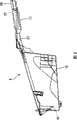
Fig. 4 is the exploded perspective view of the body tail of the same embodiment of expression.
Fig. 5 is same embodiment and the cooresponding section drawing in A-A Fig. 4 cross section of expression.
Fig. 6 is same embodiment and the cooresponding section drawing in B-B Fig. 4 cross section of expression.
Fig. 7 is the birds-eye view of the body tail that takes off the state behind the vehicle seat of the same embodiment of expression.
Fig. 8 is the partial side view in cross section of the body tail of the same embodiment of expression.
Among the figure, 7-rear portion vehicle frame (vehicle body frames), 8-accommodate case, 9-Fuel Tank, 10-seat, 17-Fuel Tank cover (Extendible flake), 23-sidepiece handle, 31-handrail, 35-load-carrying element (support portion).
The specific embodiment
Below, based on accompanying drawing, one embodiment of the present invention is described.
In addition, in the following description, so-called front side is meant the working direction of vehicle, and so-called right side and left side refer to the right side and the left side of vehicle forward direction respectively.
Fig. 1 is the lateral plan of the schematic configuration of expression automatic two-wheeled cycle of the present invention.The automatic two-wheeled cycle of this embodiment is the low-floor vehicle of so-called motor scooter type (scooter type), wherein, the pars intermedia of the Steering gear 2 that links with handle 1 is with 3 supports of head pipe of the part that is configured vehicle body frames rotationally, and front-wheel W
1Lower end side by Steering gear 2 is supported via front fork 4.In addition, on head pipe 3, be combined with the down pipe (down pipe) 6 that extends towards the lower rear of vehicle body, manage 6 rear end in this time and be combined with the rear portion vehicle frame 7 (vehicle body frames) that extends above the body tail.Rear portion vehicle frame 7 is configured in the left and right sides of car body, and links mutually in body rear end portion.
On rear portion vehicle frame 7, be equipped with side by side before and after the vehicle body be used to accommodate the helmet or goods accommodate case 8 and Fuel Tank 9, the vehicle seat 10 of the double seat type that the rider takes a seat is installed above them.This vehicle seat 10, forming in the past, end side is that open on above-below direction or closure at the hinge center.In addition, in the anterior position of this vehicle seat 10, reduce a step and be provided with and be used for the pedal 11 that the rider places pin.
In addition, on rear portion vehicle frame 7, the Power Component 12 that comprises driving engine and change-speed box via not shown pivot fulcrum and suspension link (hanger link) 13 with can be supported in the mode that above-below direction shakes, on this Power Component 12, trailing wheel W
2Be held and drive binding.In addition, between Power Component 12 and rear portion vehicle frame 7, not shown sprung parts is installed.
In addition, be provided with the pivot 15 of main support 14 at the leading section of rear portion vehicle frame 7, thus by erecting this main support 14, can vehicle seat 10 roughly under the position, support vehicle body with orthostatism.
In addition, shown in Fig. 2,3, accommodate case 8 and possess: the box main body portion 16 of upper face side opening; The fuel tank cap 17 (Extendible flake) that extends out towards the rear from the upper back edge of this box main body portion 16, and they are formed as one by resin material.Box main body portion 16 mode that rear portion side deepens gradually so that toe lateral is shallow, integral inclination above making, and, form containment member (not shown) closed contact of vehicle seat 10 sides in the outer peripheral edges portion of opening 18.In addition, as shown in Figure 4, fuel tank cap 17 has the cooresponding substantially profile of profile with the rear end side of rear portion vehicle frame 7, and covers the top of not shown vehicle seat lockout mechanism and Fuel Tank 9 continuously.
Shown in Fig. 4~8, the ora terminalis through both sides forms raised walls 20 by bending to fuel tank cap 17 from the rear portion, is formed with towards the opening 22 of the oil-feed port 21 of Fuel Tank in the substantial middle position that is surrounded by this raised walls 20.And, the front of the raised walls 20 on the left of vehicle body, the cross sectional shape of vehicle-body width direction is towards front side bending change gradually, its sweep and with the wall in the continuous vehicle body outside of this sweep, become the sidepiece handle 23 that when strutting support, makes the rider insert finger tip.In addition, at the hinder marginal part of sidepiece handle 23, be formed with the screw 24 that is used for the periphery of sidepiece handle 23 is attached to rear portion vehicle frame 7 sides.
In addition, in Fig. 4,25 expressions make the outstanding window of locking bar (not shown) of vehicle seat lockout mechanism, and 26 expressions are used to confirm the affirmation window of body number, and 27 expressions cover the lid member of this acknowledgement window 26.
On the other hand, as shown in Figure 4, on the rear portion of vehicle body both sides vehicle frame 7, be welded with the cross branch 28 that connects both at front side than rearward end, be carved with body number carriage 29 and be installed on this cross branch 28, and support the exterior region of Fuel Tank 9 by this carriage 29.The mint-mark of this carriage 29 can be confirmed by described acknowledgement window 26 from box main body 16 sides of accommodating case 8.In addition, the binding sites with cross branch 28 in the middle of the rear portion vehicle frame of vehicle body both sides 7 are compared, and more are separately installed with carriage 30 by rear side, and are combined with roughly the root 32 of both sides of the handrail 31 of " コ " shape on these carriages 30.
In addition, the root 32 in the vehicle body of handrail 31 left side, the upper limb of side screw 33 overlaps forwardly metal load-carrying element 35 (support portion), and this load-carrying element 35 is fixed together by described bolt 34 and handrail 31 and carriage 30.
Shown in Fig. 4,5,8, load-carrying element 35 is to be linked by pair of angled wall 38 by lower part wall 36 that is parallel to each other and top wall 37.And, the upper wall portions 37 relative lower part walls 36 of this load-carrying element 35 dispose to the skew of the inboard of vehicle-width direction, and lower part wall 36 is fixed together by described bolt 34 and handrail 31 and rear portion vehicle frame 7 (carriage 30), with this state, top wall 37 is fixed on the trailing edge of the sidepiece handle 23 of accommodating case 8 by bolt 39.Also have, bolt 39 is inserted to be through in the screw 24 of sidepiece handle 23, and the circumference of this screw 24 becomes the Support Position based on support portion (load-carrying element 35) on the sidepiece handle 23.The Support Position of this sidepiece handle 23, with respect to by the fixing handrail 31 of bolt 34 and the fixed position of rear portion vehicle frame 7 (carriage 30), be configured in the upper side of size of thickness of the root 32 of the height (distance between lower wall portion 36 and the upper wall portions 37) that only is equivalent to load-carrying element 35 and handrail 31.
In addition, be configured in the seat 10 of the top of accommodating case 8, on the base plate 40 that is made of hard resin seat cushion material 41 be housed, the outside of this seat cushion material 41 is covered by surface layer material 42.Base plate 40 is strengthened by not shown a plurality of muscle, and the outer peripheral edges portion at seat 10, and is crooked and form in the mode of the outer regions of the upper end that surrounds box main body portion 16 and Fuel Tank cover 17.Also have, the top position of the sidepiece handle 23 of the Fuel Tank cover 17 in this base plate 40 is formed with concavity portion 43, with the expansion upward of respective sides handle 23.
In addition, the outside of vehicle body by as Fig. 1, resinous main body cover shown in Figure 7 44 coverings, but this main body cover 44 extend in the lower side at seat 10 Fuel Tank cover 17 outer peripheral edges portion near.Also have, main body cover 44 is at the lower position of sidepiece handle 23, be provided with the recess 45 of side direction bending in vehicle body so that can easily in the curve of sidepiece handle 23, insert finger tip (with reference to Fig. 6), this recess 45 extend to sidepiece handle 23 curved shape root position under.
The automatic two-wheeled cycle of this embodiment, as explanation to above structure, constitute the upper side that the root 32 of handrail 31 is fastened on rear portion vehicle frame 7, and load-carrying element 35 is installed in the upper face side of a side root 32, the thick edge portion of sidepiece handle 23 is fastened on to the outstanding end (top wall 37) of the vehicle body inside front of this load-carrying element 35, therefore, can not make sidepiece handle 23 lateral bending song upward significantly, and sidepiece handle 23 is configured in the sufficiently high appropriate location, fastening part of relative rear portion vehicle frame 7 and handrail 31.In a word, the carriage 30 that sidepiece handle 23 is set on the relative rear portion vehicle frame 7 has position highly, described height is equivalent to the thickness of root 32 of handrail 31 and the height dimension sum of load-carrying element 35, therefore, can under the state of the degree of dwindling lateral bending song upward (it is outstanding to expand), guarantee the scope of controlling fully of steerman.
Therefore, according to this vehicle body frames, can be with sidepiece handle 23, without densification and increase considerably wall thickness or the prerequisite of additional rib etc. under, be set in suitable height.
In addition, in this embodiment, sidepiece handle 23 integral types are formed on from the Fuel Tank cover 17 of accommodating case 8 extensions, therefore, can realize the minimizing of parts number of packages and the raising of assembleability.Also have, sidepiece handle 23 can also form and accommodate the parts of case 8 splits.
Also have, in this embodiment, the load-carrying element 35 that becomes split is combined in a side's of handrail 31 the upper face side of root 32, the hinder marginal part of sidepiece handle 23 is combined in the top wall 37 of this load-carrying element 35, therefore, compare the fastening part that the support portion integral type is formed on handrail 31, and sidepiece handle 23 is combined in the situation of this support portion, only can tackle the shape of vehicle body or the difference of size easily by changing load-carrying element 35.Therefore, under the situation of this embodiment, existence can improve the design-calculated degree of freedom, and can be with handrail 31 general advantages in other car types.
In addition, in this embodiment, load-carrying element 35 is fastened on handrail 31 and the rear portion vehicle frame 7 (carriage 30) jointly by shared bolt 34, therefore, can realizes the minimizing of parts number of packages and the simplification of structure.
In addition, under the situation of this embodiment,, the top wall 37 of load-carrying element 35 is fastened on the sidepiece handle 23, therefore, can eliminates from the seat the bloating of sidepiece handle 23 of 10 side in vehicle-width direction inboard.Therefore, can the densification vehicle body, improve designability.
Also have, in this mounting structure, the restraint location that utilizes load-carrying element 35 fastening sidepiece handles 23 is set in the top of Fuel Tank 9, therefore, Fuel Tank 9 is difficult for beared part 35 or the restriction of sidepiece handle, otherwise, improve design-calculated degree of freedom such as the shape of Fuel Tank 9 or size, also be easy to guarantee the capacity of Fuel Tank 9.
Also have, the present invention is not limited to above-mentioned embodiment, and can adopt various design modifications in the scope that does not exceed its aim.For example, adopt the automatic two-wheeled cycle of this body construction to be not limited to the low-floor vehicle of motor scooter type, also go for the vehicle of other types.
Claims (7)
1. the body structure of an automatic two-wheeled cycle, the handrail that is supported by vehicle body frames is outstanding to be located at the rear side at the seat that the rider takes a seat, and below described seat sidepiece, be provided with and be used to make the rider that hand is inserted to support the sidepiece handle of vehicle body from lower side, it is characterized in that
The root of described handrail is fastened on the vehicle body frames, and the load-carrying element that supports described sidepiece handle is installed at the upper face side of the root of this handrail, with the thick edge portion of sidepiece handle be fastened on this load-carrying element to the outstanding end of vehicle body inside front,
To be set in the more top of comparing with the fastening position of handrail and vehicle body frames by the Support Position of this support member support sidepiece handle.
2. the body structure of automatic two-wheeled cycle according to claim 1 is characterized in that,
Described seat is set as and can opens and closes, and below this seat, disposes and accommodate case,
The described case of accommodating is provided with the Extendible flake that extends rearward, and integral type forms described sidepiece handle on this Extendible flake.
3. the body structure of automatic two-wheeled cycle according to claim 1 and 2 is characterized in that,
Constitute described load-carrying element with described handrail and vehicle body frames split ground, this load-carrying element is fixed on the described handrail.
4. the body structure of automatic two-wheeled cycle according to claim 3 is characterized in that,
Described load-carrying element is fastened on the fastening position of described handrail and vehicle body frames.
5. according to the body structure of each the described automatic two-wheeled cycle in the claim 1,2,4, it is characterized in that,
With the Support Position of the described sidepiece handle on the described load-carrying element, be set in the below at described seat, more rely on the position of overall width direction inboard than the fastening position of described handrail and vehicle body frames.
6. the body structure of automatic two-wheeled cycle according to claim 2 is characterized in that,
Described Extendible flake is the Fuel Tank cover that covers Fuel Tank,
To be set in the top of comparing with Fuel Tank by the Support Position of described support member support sidepiece handle.
7. the body structure of automatic two-wheeled cycle according to claim 1 is characterized in that,
Described load-carrying element possesses a pair of lower part wall that is parallel to each other and top wall, links this lower part wall and top wall with the pair of angled wall, and the relative lower part wall of top wall is in the inboard offset configuration of vehicle-width direction.
Applications Claiming Priority (2)
| Application Number | Priority Date | Filing Date | Title |
|---|---|---|---|
| JP2005102505A JP4476857B2 (en) | 2005-03-31 | 2005-03-31 | Motorcycle body structure |
| JP2005102505 | 2005-03-31 |
Publications (2)
| Publication Number | Publication Date |
|---|---|
| CN1840410A CN1840410A (en) | 2006-10-04 |
| CN100447036C true CN100447036C (en) | 2008-12-31 |
Family
ID=37029664
Family Applications (1)
| Application Number | Title | Priority Date | Filing Date |
|---|---|---|---|
| CNB2006100716182A Expired - Fee Related CN100447036C (en) | 2005-03-31 | 2006-03-28 | Body structure of automotive bicycle |
Country Status (5)
| Country | Link |
|---|---|
| JP (1) | JP4476857B2 (en) |
| KR (1) | KR100718061B1 (en) |
| CN (1) | CN100447036C (en) |
| IT (1) | ITTO20060196A1 (en) |
| TW (1) | TWI286110B (en) |
Families Citing this family (7)
| Publication number | Priority date | Publication date | Assignee | Title |
|---|---|---|---|---|
| JP5409208B2 (en) * | 2009-08-31 | 2014-02-05 | 本田技研工業株式会社 | Under-seat cover structure for saddle-ride type vehicles |
| JP5560059B2 (en) * | 2010-01-29 | 2014-07-23 | 本田技研工業株式会社 | Saddle riding |
| JP5872447B2 (en) * | 2012-12-13 | 2016-03-01 | 本田技研工業株式会社 | Rear structure of saddle-ride type vehicle |
| JP6132627B2 (en) * | 2013-03-29 | 2017-05-24 | 本田技研工業株式会社 | Gripping part structure of saddle riding type vehicle |
| CN108263525B (en) * | 2016-12-30 | 2020-04-03 | 雅马哈发动机株式会社 | Saddle-ride type vehicle |
| CN108688754B (en) * | 2017-03-31 | 2021-07-09 | Tvs电机股份有限公司 | Striding type vehicle |
| CN109131653B (en) * | 2017-06-15 | 2022-05-24 | Tvs电机股份有限公司 | Backseat handle for two-wheeled vehicle |
Citations (5)
| Publication number | Priority date | Publication date | Assignee | Title |
|---|---|---|---|---|
| CN1114619A (en) * | 1994-04-04 | 1996-01-10 | 本田技研工业株式会社 | Structure for supporting container box disposed under seat in small-size vehicle |
| CN1449962A (en) * | 2002-04-11 | 2003-10-22 | 本田技研工业株式会社 | Seat locking device and armrest lever installation structure for two-wheel motocycle |
| CN1504382A (en) * | 2002-12-04 | 2004-06-16 | 本田技研工业株式会社 | Bodywork structure of two-wheel motor |
| JP2004299627A (en) * | 2003-03-31 | 2004-10-28 | Honda Motor Co Ltd | Grab rail of motorcycle |
| CN1597423A (en) * | 2003-09-18 | 2005-03-23 | 本田技研工业株式会社 | Luggage carrier device |
Family Cites Families (1)
| Publication number | Priority date | Publication date | Assignee | Title |
|---|---|---|---|---|
| JP2772430B2 (en) | 1989-03-31 | 1998-07-02 | スズキ株式会社 | Scooter stand grip |
-
2005
- 2005-03-31 JP JP2005102505A patent/JP4476857B2/en not_active Expired - Fee Related
-
2006
- 2006-02-22 TW TW095105959A patent/TWI286110B/en active
- 2006-03-13 IT IT000196A patent/ITTO20060196A1/en unknown
- 2006-03-28 CN CNB2006100716182A patent/CN100447036C/en not_active Expired - Fee Related
- 2006-03-30 KR KR1020060028833A patent/KR100718061B1/en not_active IP Right Cessation
Patent Citations (5)
| Publication number | Priority date | Publication date | Assignee | Title |
|---|---|---|---|---|
| CN1114619A (en) * | 1994-04-04 | 1996-01-10 | 本田技研工业株式会社 | Structure for supporting container box disposed under seat in small-size vehicle |
| CN1449962A (en) * | 2002-04-11 | 2003-10-22 | 本田技研工业株式会社 | Seat locking device and armrest lever installation structure for two-wheel motocycle |
| CN1504382A (en) * | 2002-12-04 | 2004-06-16 | 本田技研工业株式会社 | Bodywork structure of two-wheel motor |
| JP2004299627A (en) * | 2003-03-31 | 2004-10-28 | Honda Motor Co Ltd | Grab rail of motorcycle |
| CN1597423A (en) * | 2003-09-18 | 2005-03-23 | 本田技研工业株式会社 | Luggage carrier device |
Also Published As
| Publication number | Publication date |
|---|---|
| JP2006281920A (en) | 2006-10-19 |
| JP4476857B2 (en) | 2010-06-09 |
| KR20060105564A (en) | 2006-10-11 |
| TWI286110B (en) | 2007-09-01 |
| KR100718061B1 (en) | 2007-05-14 |
| ITTO20060196A1 (en) | 2006-10-01 |
| CN1840410A (en) | 2006-10-04 |
| TW200706434A (en) | 2007-02-16 |
Similar Documents
| Publication | Publication Date | Title |
|---|---|---|
| CN100447036C (en) | Body structure of automotive bicycle | |
| CN100548779C (en) | But the armchair structure that is used for the longitudinal sliding motion of two-wheeled or three-wheeled vehicle | |
| US6336579B1 (en) | Helmet storage area for motorcycles | |
| US5388660A (en) | Motor bicycle | |
| EP1818249B1 (en) | Motorcycle comprising a rear cushion arrangement structure | |
| EP1188651B1 (en) | Container box structure in two-wheeled motor vehicle | |
| US20100012411A1 (en) | Vehicle storage compartment | |
| CN1840408A (en) | Body structure of automotive bicycle | |
| JP4549916B2 (en) | Motorcycle body structure | |
| EP2213565B1 (en) | Article storage structure of motorcycle | |
| EP2055621B1 (en) | Vehicle having an article storing structure | |
| EP2246244A1 (en) | Two-wheeled motor vehicle | |
| EP1319591B1 (en) | Straddle type of vehicle | |
| CN100406334C (en) | Body structure of automatic two-wheeled vehicle | |
| JP4573682B2 (en) | Motorcycle | |
| CN100377960C (en) | Pannier device | |
| JP2950847B2 (en) | Motorcycle | |
| JP2694337B2 (en) | Scooter type vehicle | |
| JP2552222B2 (en) | Helmet storage box device for scooter type vehicle | |
| WO2021186460A1 (en) | A saddle type vehicle and a seat-structure thereof | |
| JP2024051349A (en) | Storage box structure | |
| JP2564314B2 (en) | Motorcycle steering system | |
| JP4548852B2 (en) | Saddle riding vehicle | |
| JPS6313850B2 (en) | ||
| JPH072155A (en) | Pocket device for scooter type vehicle |
Legal Events
| Date | Code | Title | Description |
|---|---|---|---|
| C06 | Publication | ||
| PB01 | Publication | ||
| C10 | Entry into substantive examination | ||
| SE01 | Entry into force of request for substantive examination | ||
| C14 | Grant of patent or utility model | ||
| GR01 | Patent grant | ||
| CF01 | Termination of patent right due to non-payment of annual fee |
Granted publication date: 20081231 Termination date: 20200328 |
|
| CF01 | Termination of patent right due to non-payment of annual fee |