CN100441422C - Roll paper transportation device and printing apparatus - Google Patents
Roll paper transportation device and printing apparatus Download PDFInfo
- Publication number
- CN100441422C CN100441422C CNB2006100743921A CN200610074392A CN100441422C CN 100441422 C CN100441422 C CN 100441422C CN B2006100743921 A CNB2006100743921 A CN B2006100743921A CN 200610074392 A CN200610074392 A CN 200610074392A CN 100441422 C CN100441422 C CN 100441422C
- Authority
- CN
- China
- Prior art keywords
- paper
- coil paper
- test rod
- coil
- buffer board
- Prior art date
- Legal status (The legal status is an assumption and is not a legal conclusion. Google has not performed a legal analysis and makes no representation as to the accuracy of the status listed.)
- Active
Links
Images


Classifications
-
- B—PERFORMING OPERATIONS; TRANSPORTING
- B41—PRINTING; LINING MACHINES; TYPEWRITERS; STAMPS
- B41J—TYPEWRITERS; SELECTIVE PRINTING MECHANISMS, i.e. MECHANISMS PRINTING OTHERWISE THAN FROM A FORME; CORRECTION OF TYPOGRAPHICAL ERRORS
- B41J15/00—Devices or arrangements of selective printing mechanisms, e.g. ink-jet printers or thermal printers, specially adapted for supporting or handling copy material in continuous form, e.g. webs
- B41J15/16—Means for tensioning or winding the web
- B41J15/165—Means for tensioning or winding the web for tensioning continuous copy material by use of redirecting rollers or redirecting nonrevolving guides
-
- B—PERFORMING OPERATIONS; TRANSPORTING
- B41—PRINTING; LINING MACHINES; TYPEWRITERS; STAMPS
- B41J—TYPEWRITERS; SELECTIVE PRINTING MECHANISMS, i.e. MECHANISMS PRINTING OTHERWISE THAN FROM A FORME; CORRECTION OF TYPOGRAPHICAL ERRORS
- B41J11/00—Devices or arrangements of selective printing mechanisms, e.g. ink-jet printers or thermal printers, for supporting or handling copy material in sheet or web form
- B41J11/0095—Detecting means for copy material, e.g. for detecting or sensing presence of copy material or its leading or trailing end
-
- B—PERFORMING OPERATIONS; TRANSPORTING
- B41—PRINTING; LINING MACHINES; TYPEWRITERS; STAMPS
- B41J—TYPEWRITERS; SELECTIVE PRINTING MECHANISMS, i.e. MECHANISMS PRINTING OTHERWISE THAN FROM A FORME; CORRECTION OF TYPOGRAPHICAL ERRORS
- B41J15/00—Devices or arrangements of selective printing mechanisms, e.g. ink-jet printers or thermal printers, specially adapted for supporting or handling copy material in continuous form, e.g. webs
- B41J15/04—Supporting, feeding, or guiding devices; Mountings for web rolls or spindles
- B41J15/042—Supporting, feeding, or guiding devices; Mountings for web rolls or spindles for loading rolled-up continuous copy material into printers, e.g. for replacing a used-up paper roll; Point-of-sale printers with openable casings allowing access to the rolled-up continuous copy material
-
- B—PERFORMING OPERATIONS; TRANSPORTING
- B65—CONVEYING; PACKING; STORING; HANDLING THIN OR FILAMENTARY MATERIAL
- B65H—HANDLING THIN OR FILAMENTARY MATERIAL, e.g. SHEETS, WEBS, CABLES
- B65H26/00—Warning or safety devices, e.g. automatic fault detectors, stop-motions, for web-advancing mechanisms
Abstract
A roll paper transportation device and printing apparatus using it reduce the space needed to accommodate a roll paper buffer unit (7) and paper detection unit (8), and reduce poor electrical contact in a contact part of the paper detection unit (8). The roll paper transportation device has the paper detection unit (8) for detecting the presence of roll paper roll paper (5), and a buffer unit (7) for absorbing variations in tension of the roll paper (5) in order to keep the roll paper tension less than or equal to a predetermined level. The paper detection unit (8) is accommodated in a recess formed in the buffer unit (7) in such a way that each is prevented from interfering with the operation of the other.
Description
Technical field
The present invention relates to be used for transmitting reposefully the roll paper transportation device of coil paper, and the PRN device that comprises described roll paper transportation device.
Background technology
Use the conventional printer of coil paper to have tension force usually and absorb buffer gear, be used for tension force with coil paper and remain and be less than or equal to predeterminated level.This buffer gear is supported so that can flexibly move, thereby makes the tension force on the coil paper keep constant.For example, referring to the open H06-8554 of Japanese unexamined patent.
Known a kind of structure with buffer board, described buffer board are used to slow down when beginning to carry coil paper by the high-tension that inertia produced of mandrel, and wherein paper is reeled round refill.Along with the increase of the diameter of coil paper core, inertia increases.Compare with the printer that coil paper is supported on the axle, only be placed on a what is called in the winding paper chamber * winding paper simply at coil paper and fall into formula and load printer (drop-in loading printer), the inertia of refill especially greatly, the tension force that is produced is also big.
The paper detecting unit can be set near buffer board, be used for detecting whether coil paper is arranged.The friction that coil paper is produced during carrying can produce static, and these static can gather, be discharged to then near the paper detecting unit the paper transport path, can damage or destroy the paper detecting unit like this.If the paper detecting unit uses photoelectric sensor, then the position of circuit unit can make that circuit is damaged especially easily on sensor surface, because electrostatic charge can directly be discharged to circuit unit.The metal buffer plate can be set around photoelectric sensor, thereby so that avoid static discharge by the most electrostatic charge of metal buffer plate loss, prevent thus the photoelectric sensor discharge, for example as instructing among the open 2000-62281 of Japanese unexamined patent.Yet this needs complicated metal process operation with the shaping buffer board, has increased cost thus.In addition, buffer board must be electrically connected to framework by for example lead etc., so as reliably from buffer board discharging electrostatic charge to framework, so further make complex structure and cost increased.
Can be with the photoelectric sensor in the layout replacement paper detecting unit that uses mechanical switch, as avoiding by a kind of means of static damage.Fig. 7 is the cutaway view of paper detecting unit and buffer gear in the traditional thermal printer.As shown in Figure 7, these printer 30 maintenance coil papers 31 are wound on paper roll 32 wherein.Coil paper 31 remains between printhead 33 and the platen parts 34.Rotation platen parts 34 advance coil paper 31.The existence that detects coil paper 31 was moved in the position of switch lever 38 when paper detecting unit 37 pivoted according to switch lever 38.Inserting switch lever 38 can make paper detecting unit 37 and coil paper 31 separate.In addition, switch lever can be made by plastics or other electrically non-conductive materials, so that can prevent that static discharge that coil paper 31 produces is to paper detecting unit 37.The direction that the buffer board 36 of buffer gear 35 and the switch lever 38 of paper detecting unit 37 are carried along coil paper 31 is arranged on the transport path between paper roll 32 and the platen parts 34.Buffer board 36 can wave, thereby the inertia that can absorb paper roll 32 when beginning to carry coil paper is applied to the high tension on the coil paper 31.
The paper detecting unit 37 that is used to detect coil paper 31 comprises switch lever 38 and mechanical switch 39.Switch lever 38 touches coil paper 31 and can pivot.If there is coil paper 31, switch lever 38 pivots and moves to position Q, makes contact lever 40 (contact terminal) in the contact portion 41 contact mechanical switch 39 on switch lever 38 ends.If there is no coil paper 31, and then switch lever 38 moves to position P, thereby separate and cut-off switch with contact lever 40.When coil paper 31 is loaded and during contact-making switch bar 38, switch lever 38 pivots and moves to position Q, contact portion 41 contact contact levers 40, and switch connection.The change of the open/close state by switch can detect whether there is coil paper 31.
The problems of the prior art of instructing in Japanese unexamined patent publication H06-8554 are, need buffer gear between paper roll 32 and platen parts 34, and described buffer gear needs big installing space.As shown in Figure 7, between paper roll 32 and platen parts 34, need long distance L 1, so that buffer gear 35 and paper detecting unit 37 are set along the throughput direction of coil paper 31.
Further, so that when avoiding infringement that static discharge causes, produced the distinctive problem of mechanical switch when using mechanical switch to replace photoelectric sensor to be used as the paper detecting unit.When coil paper 31 was transmitted, the vertical variation of moving of paper made the position of switch change during load variations that the friction of carrying owing to coil paper move left and right and coil paper causes and coil paper were carried.Though be slight variation,, even the position of coil paper 31 also can change between coil paper position R1 and R2 repeatedly when using buffer board 36.When the position of coil paper 31 changed, switch lever 38 also pivoted repeatedly, although the distance that moves is small, thus, contact also slip (at the on-position of switch) repeatedly with contact lever 40 at contact portion 41 place's switch levers 38 of mechanical switch 39.On contact portion 41, produce wearing and tearing so gradually, cause poor electric contact at last.
In order to address these problems, the purpose of this invention is to provide a kind of roll paper transportation device and PRN device, they can make and put buffer gear and the required space of paper detecting unit minimizes, and can prevent to be used in the poor electric contact of the contact site office of the mechanical switch in the paper detecting unit.
Summary of the invention
In order to realize this purpose, roll paper transportation device according to the present invention is the device that is used to transmit coil paper, and comprise and be used to detect paper detecting unit and the buffer gear unit whether coil paper exists, described buffer gear unit is used to absorb the variation of coil paper tension force, is less than or equal to predetermined tension force so that tension force is remained.The paper detecting unit is arranged in the accomodating unit of buffer gear unit, and is integral with the buffer gear unit.
This roll paper transportation device can remain on paper detecting unit and buffer gear unit in the accomodating unit of buffer gear unit together.More specifically, compare with the layout that the paper detecting unit is arranged in diverse location with the buffer gear unit, by whole paper detecting unit is positioned in the shared zone, buffer gear unit, putting the required space of buffer gear unit and paper detecting unit can reduce significantly.Paper detecting unit and buffering unit can also be operated independently, and do not interfere with the operation of other devices.Therefore, can in the function that realizes paper detecting unit and roll paper transportation device, provide compacter roll paper transportation device.
Preferably, the buffer gear unit comprises buffer board, and described buffer board is provided with perpendicular to the coil paper throughput direction, and buffer board provides the guidance surface that forms the coil paper transport path.More preferably, buffer board is the coil paper transport path is waved so that absorb the layout of the tension force on the coil paper.
The buffer board of the buffer gear unit of this aspect is provided for guiding the guidance surface of coil paper according to the present invention.The guidance surface of buffer board is arranged on the position that changes the coil paper throughput direction, along guidance surface guiding coil paper, and the side-to-side movement of compensation coil paper and moving both vertically.Thus, by on this guidance surface, guiding coil paper, can correctly guide coil paper along throughput direction.And buffer board is constructed to make the coil paper transport path to wave.When such as coil paper when printing beginning suddenly when paper roll is extracted out, the tension force instantaneous pole the earth on the coil paper increases.The high-tension that is produced (or change of tension force) can disturb normal paper to carry or hinder the normal conveying of paper, and the result causes the uneven stretching of coil paper, wrinkling even be torn.And the excessive load that is produced on defeated paper motor can stop motor normally to move, even can damage motor, and for fear of such problem, when high-tension was applied on the coil paper suddenly, buffer board waved along the direction that reduces this tension force.This waving prevented that hightension was applied on the coil paper.
Further preferably, be used to detect the paper detecting unit whether coil paper exist and have test rod, test rod pivots when contacting with coil paper, and test rod be a kind of when test rod contact with coil paper and buffer board when waving and guidance surface together pivot, thereby test rod can not project to the layout of coil paper side separately from the guidance surface of buffer board.
The paper detecting unit of this aspect has test rod according to the present invention, and described test rod is configured to: when coil paper is loaded and during the contact detection bar, coil paper is depressed test rod, and the operation of paper detecting unit, whether be loaded thereby detect coil paper.When tension force is applied to coil paper, and buffer board is when pivoting, and test rod and buffer board together pivot, and is maintained at not separately from the position that the guidance surface of buffer board is given prominence to.If test rod does not together move with guidance surface, and outstanding from guidance surface separately, then the coil paper end of test rod that will rub stays the strip line or the marking, thereby produce print defect on the coil paper that is printed on paper.If the use heat-sensitive paper, decolouring becomes and can not use thereby this friction can make paper.By the test rod that together moves and do not give prominence to from guidance surface with guidance surface is provided, the papery of the coil paper through printing can variation.
Further preferably, being used to detect the direction that direction that test rod that whether coil paper exist buffer board when contacting coil paper with test rod extends parallels pivots.
Whether the pivot that the direction of the direction almost parallel that the paper detecting unit of this aspect can extend according to test rod buffer board when being loaded with coil paper and contacting with test rod according to the present invention is carried out detects coil paper and exists.By being parallel to the rotation of buffer board direction, test rod is followed the rotate path that is included in the buffer gear unit area, and wherein buffer board is arranged at the buffer gear unit.Therefore, even test rod pivots by big rotate path, test rod also can move in the scope of buffer gear unit, and does not need to provide the independent space that allows test rod to pivot.Therefore, only need less space to put the paper detecting unit.
The roll paper transportation device that transmits coil paper comprised and was used to detect the paper detecting unit whether coil paper exists being used to according to a further aspect of the invention.The paper detecting unit comprises: test rod, and described test rod pivots when coil paper exists, so that detect coil paper; The cam integrally formed with test rod, described cam have the curved surface concentric with the test rod pivot; And switch lever, the curved surface of described switch lever contact cam.
It is that coil paper does not exist that the paper detecting unit of this roll paper transportation device detects.When coil paper is loaded and during the contact detection bar, the test rod of paper detecting unit is depressed and pivots.Thereby when test rod pivoted, the cam integrally formed with test rod also rotated.Cam has the curved surface concentric with the test rod pivot.When cam rotated, switch lever was promoted by the curved surface of cam and waves, thereby moves to and the curved surface position contacting from the position of separating with the curved surface of cam, thereby can operate machine switch.
More specifically, when switch lever was promoted by the curved surface of cam, the switch lever in the mechanical switch waved and contacts contact terminal, thereby operates machine switch.And,, therefore,, can amplify by coil paper and be applied to the little power on the switch lever and the switch of can operating machine reliably by the length of adjusting lever and the shape of cam because by test rod, cam and the switch lever switch of operating machine.Use test rod and cam can also increase the distance from the coil paper to the mechanical switch, and it is electrostatic discharged to mechanical switch to prevent reliably that coil paper from producing.
Also preferably, when coil paper is loaded, and test rod is depressed by coil paper and when pivoting, the curved surface of the cam that switch lever contact and test rod together rotate.
Of the present invention aspect this in, when coil paper was loaded, switch lever was followed cam and is ridden the curved surface that leans against cam and contact with this curved surface.Switch lever is ridden on the curved surface that leans against cam, the contact terminal of contact mechanical switch, and the switch of operating machine.Load changes when transmitting coil paper, and this change of test rod and load is when together and repeatedly mobile, and switch lever slides along the curved surface of cam, but does not wave, because the cam face of bending is concentric with the pivot of test rod.More specifically, when the position of coil paper slightly changed, switch lever did not pivot repeatedly, and therefore, switch lever does not slide against the contact terminal of mechanical switch.Thus, contact terminal that can the limit mechanical switch and the slip between the switch lever, and badly electrically contacting of can preventing that the contact wearing and tearing that caused by this slip and contact wearing and tearing from causing.
PRN device according to a further aspect of the invention is the PRN device that comprises according to roll paper transportation device of the present invention.
This PRN device comprises the paper detecting unit that provides integrally formed and the compact roll paper transportation device of buffer gear unit.As a result, the wabbler mechanism of the buffer board that PRN device can be by the buffer gear unit is alleviated the generation of crossing hightension on the coil paper.And, can be not outstanding from the guidance surface of buffer board independently because detect the test rod of coil paper, therefore, can prevent the damage that produces owing to test rod friction coil paper.And, when in the paper detecting unit, using mechanical switch, contact terminal that can the limit mechanical switch and the slip between the switch lever, and can prevent because the contact friction that this slip causes and because contact friction causes badly electrically contacts.Can also prevent discharging, thereby can also prevent from the paper detecting unit is produced infringement by the static of coil paper generation.Thereby, can provide the compact PRN device of realizing above-mentioned advantage in the PRN device by roll paper transportation device of the present invention is arranged at.
The following description and the claim of carrying out in conjunction with the drawings will become apparent than complete understanding and other purposes of the present invention and achievement of the present invention.
Description of drawings
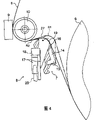
Fig. 1 is the perspective view of PRN device outside;
Fig. 2 is a cutaway view of describing the relative position of the paper detecting unit of roll paper transportation device and buffer gear unit;
Fig. 3 illustrates the cutaway view that is loaded in the coil paper in the roll paper transportation device;
Fig. 4 illustrates the cutaway view of carrying coil paper when tension force is applied on the coil paper;
Fig. 5 is the front view that paper detecting unit when coil paper does not exist is shown;
Fig. 6 is the front view that paper detecting unit when coil paper exists is shown;
Fig. 7 is the cutaway view that paper detecting unit and buffer gear in the traditional thermal printer are shown.
[Reference numeral]
1. printer 4. covers
5. coil paper 6. paper rolls
7. buffer cell 8. paper detecting units
9. printhead 10. platen parts
14. buffer board 16. accomodating units
17. test rod 18. test rod pivots
19. guidance surface 20. cams
21. curved surface 22. mechanical switch
23. switch lever 24. contact levers
25. contact 27. far-ends
The specific embodiment
Below with reference to the preferred embodiment of accompanying drawing description according to roll paper transportation device of the present invention and PRN device.
Fig. 1 is the perspective view of PRN device outside.Fig. 2 is the cutaway view that the relative position of the paper detecting unit of roll paper transportation device and buffer gear unit is shown.Fig. 3 illustrates the cutaway view that is loaded in the coil paper in the roll paper transportation device.
As shown in Figure 1, printer 1 has drain pan 2 and top shell 3.Top shell 3 has and covers 4, and described lid 4 freely opens and closes on printer 1.Be arranged on by opening the parts that cover in 4 spaces that just can enter and comprise: paper roll 6 (there is shown a part), by coil paper 5 coilings are formed described paper roll 6; Buffer cell 7, described buffer cell 7 are used to absorb the change of tension force so that the tension force of coil paper 5 is remained the predetermined tension degree that is equal to or less than; Accomodating unit 16, described accomodating unit 16 is rendered as the cut-out of buffer cell 7; Paper detecting unit 8, whether described paper detecting unit 8 is arranged in the accomodating unit 16, be used to detect coil paper 5 and exist; And printhead 9, be used for coil paper 5 is printed.Platen parts 10 are arranged at and cover on 4, so that by closing cap 4 coil paper 5 is remained between platen parts 10 and the printhead 9.Transmit coil paper 5 by rotation platen parts 10, and printhead 9 is printed on coil paper 5.
Be used to open and cover 4 lid and open the top that button 11 is positioned at top shell 3, and power switch 12 is positioned at the front portion of top shell 3.As shown in Figure 3, buffer cell 7 has buffer board 14.Buffer cell 7 is directed to printhead 9 with coil paper 5, and buffering is applied to the high-tension on the coil paper 5.Buffer board 14 pivots around buffer board pivot 15, so that absorb tension force, and pivots (waving) to printhead 9 when tension force increases, and returns to paper roll 6 when tension force reduces.Therefore, buffer board 14 with the direction of rotation of buffer board 14 substantially rectangular mode (coil paper 5 widths) extend, thereby buffer board 14 can be guided coil paper 5.
For coil paper 5 is loaded in the printer 1, lid is opened button 11 and is depressed and cover 4 to open, and as shown in Figure 1, then, paper roll 6 is placed in the top shell 3, formation state as shown in Figure 2.Then, coil paper 5 is pulled out from paper roll 6 along the direction of printhead 9, so that coil paper 5 covers the guidance surface 19 of buffer cell 7 and buffer board 14, and wherein said guidance surface 19 guiding coil papers 5.Like this, the operation of closing cap 4 makes coil paper 5 pass transport path after paper roll 6 pulling and the location coil paper 5, as shown in Figure 3, covers 4 platen parts 10 coil paper 5 is pressed against printhead 9 and be connected to.Make coil paper 5 push away the test rod 17 of paper detecting unit 8 like this, thus make when do not load coil paper 5 when (not having coil paper) test rod 17 pivot and drop to position Q from the position P of test rod 17.Test rod 17 pivots around test rod pivot 18 along the direction (coil paper 5 widths) that roughly parallels with buffer board 14 bearing of trends.
Buffer cell 7 is between paper roll 6 and platen parts 10.Paper detecting unit 8 is included in the accomodating unit 16 that is arranged in the buffer cell 7.Compare (as shown in Figure 7) with buffer cell 7 is provided separately with the structure of paper detecting unit 8, this structure has greatly reduced to offer the required space of buffer cell 7 and paper detecting unit 8.Like this, the distance L 2 among Fig. 2 between paper roll 6 and the platen parts 10 can be shorter than the distance L between paper roll among Fig. 7 32 and the platen parts 34 1, thereby can reduce overall dimensions in the functional while that keeps buffer gear unit and paper detecting unit.
Be loaded in coil paper 5 in the printer 1 from paper roll 6 guidance surface 19, reach then to platen parts 10 through buffer boards 14.As shown in Figure 3, make the test rod 17 of paper detecting unit 8 descend like this, and test rod 17 pivots and move, make test rod 17 fully and buffer board 14 (coil paper 5 widths) in line.Pivot by test rod 17 utilizes switch lever 23 switch 22 of operating machine, and detects whether there is coil paper 5 by mechanical switch 22.Coil paper 5 is through between platen parts 10 and the printhead 9, and the pressure that passes through platen parts 10 is against printhead 9.Then, transmit coil paper 5 by utilizing unshowned feeding motor to drive platen parts 10 rotatably.Then, when coil paper 5 was transmitted, printhead 9 was printed on coil paper 5, and coil paper 5 is outwards drained into printer 1.Unshowned automatic paper cutter cuts into coil paper 5 length that is suitable for removing.
The rotation of platen parts 10 makes coil paper 5 be pulled from paper roll 6, and coil paper 5 is conducted to printhead 9.In this embodiment of the present invention, printhead 9 is thermal printing heads, and coil paper 5 is heat-sensitive papers.The heat that heater element produced that is conducted to 5 pairs of printheads 9 of coil paper of printhead 9 reacts and changes color.Printer 1 changes the position of color by control coil paper 5 and prints as required.
Shown in Fig. 2 and 3, roll paper transportation device comprises supply unit, and described supply unit is used for keeping and transmitting coil paper 5 by printhead 9 and platen parts 10, buffer cell 7 and paper detecting unit 8.
The conveying of coil paper 5 then will be described.
This printer 1 is not that paper roll 6 is supported on the main shaft, falls into the formula Load System and be to use, and makes the user can simply paper roll 6 be packed in the winding paper chamber * winding paper in the top shell 3.Use falls into the formula Load System makes the user simply paper roll 6 to be arranged on printer 1, because do not need to make the center of main shaft through paper roll 6.When beginning to print, thereby platen parts 10 begin rotation when beginning that coil paper 5 is delivered to printhead 9, and static paper roll 6 must rotation, so that coil paper 5 is pulled down from paper roll 6.In order to spur coil paper 5, paper roll 6 must be with fully big power rotation with the friction that overcomes transport path and make paper roll 6 keep static inertia.Like this, special meeting produces high tension force in coil paper 5, and big load can be applied to the motor that is used to drive platen parts 10.Because in recent printer, print speed speeds, therefore, the supply rate of coil paper 5 also increases, and can produce bigger tension force like this, and can apply bigger load to motor.Along with the increase of paper roll 6 diameters, inertia also increases.When paper roll 6 is replaced, load new paper roll 6, so reel diameter becomes big.As a result, the tension force height on the coil paper 5.These factors make and are applied on the motor even as big as the load that hinders the electric motor starting rotation.If employed motor is a direct current generator, then this can cause overcurrent, and overcurrent can be damaged motor in the worst case.If use stepper motor, this load can make motor lose synchronously, the result can damage motor.
If motor begins rotation, the rotation of platen parts 10 starts drag coil paper 5, and begins coil paper 5 is supplied to printhead 9.At this moment, the tension force on coil paper 5 is temporarily higher, can make like this that coil paper is 5 wrinkling, stretches or even tear to shreds, and these problems do not take place during coil paper 5 is carried usually.If printer 1 is the POS printer that is used to print the cash income receipt, different receipts is printed in then corresponding trade fair each time, and the conveying of coil paper 5 begins continually and stops, and makes above-mentioned because the problem that the high-tension of paper causes takes place repeatedly.
In order to address this problem, printer 1 according to the present invention has buffer cell 7, is used to cushion the tension force on the coil paper 5 and the variation of the load on the motor.Fig. 4 shows the cutaway view under the high situation of tension force on the coil paper wherein.For example, when platen parts 10 began rotation with the startup printing after printer 1 stops, the inertia of paper roll 6 made high tension force be applied on the coil paper 5.The impeller that promotes buffer board 14 towards paper roll 6 is arranged in the buffer cell 7.When the tension force on the coil paper 5 was higher, the described buffer board 14 of buffer cell 7 pivoted around buffer board pivot 15 in this tension force of antagonism.When buffer board 14 during towards platen parts 10 rotation, the tension force in the buffer cell 7 on the motive force of the impeller buffering coil paper 5.As a result, when platen parts 10 begin to rotate, can begin the conveying of coil paper 5, and on motor, not produce instantaneous high capacity.Fig. 4 shows the buffer board 14 that rotates towards platen parts 10 to greatest extent by this instantaneous high capacity.The buffer cell 7 that is used to absorb the variation of coil paper tension force can make tension force remain to be less than or equal to predetermined tension force (less than maximum tension).When coil paper 5 was normally carried, buffer board 14 was not switched to position shown in Figure 4.
When paper roll 6 begins rotation, and coil paper 5 beginning is when advancing with constant speed, and the load relevant with transmitting coil paper 5 is determined by following amount: the inertia that is reduced of paper roll 6; Friction load between the surface of paper roll 6 and top shell 3, wherein paper roll 6 is placed on the top shell 3; And the guidance surface 19 of buffer board 14 and the friction load of coil paper 5, wherein said guidance surface 19 guiding coil papers 5.These friction loads are lower.Like this, buffer board 14 was returned to paper roll 6 by the position that the high-tension on the coil paper 5 is pivoted to when the impeller of buffer board 14 from buffering unit 7 started the coil paper conveying operations, because coil paper tension force descends when carrying continuation.This tension force buffering that rotation provided of buffer board 14 prevents that excessive tension force is applied on the coil paper.
When the far-end 27 of the test rod 17 that detects coil paper 5 contacted with coil paper 5, shown in Fig. 3 and 4, far-end 27 and guidance surface 19 were in same plane.As shown in Figure 3, when coil paper 5 is loaded, and cover 4 when being closed, the far-end 27 of test rod 17 moves to position Q from position P.At this moment, tension force is not applied on the coil paper 5, and buffer board 14 does not pivot.When the far-end 27 contact coil papers 5 of test rod 17, far-end 27 rotate to guidance surface 19 in same plane, and the switch 22 of operating machine.Like this, detect the loading of coil paper 5.
When platen parts 10 begin rotation, and high tension force is when being applied on the coil paper 5, and buffer board 14 pivots towards platen parts 10, and buffering tension force, as shown in Figure 4.Along with buffer board 14 rotations, the far-end 27 of the contact detection bar 17 of coil paper 5 contact guidance surfaces 19 moves to coil paper position R2 from coil paper position R1.Like this, far-end 27 and guidance surface 19 are switched to coil paper position R2 simultaneously.When coil paper 5 when coil paper position R1 moves to coil paper position R2, far-end 27 and guidance surface 19 also remain in the same plane when moving.
No matter buffer board 14 is shifted to paper roll 6 or platen parts 10, and far-end 27 always together pivots with buffer board 14, remain in the same plane with the guidance surface 19 of buffer board 14, and far-end 27 can not given prominence in the path that extend into coil paper 5 separately.Therefore, by the local part of lifting coil paper 5, far-end 27 can not cause that coil paper is wrinkling, produce mark on coil paper 5 or coil paper 5 is produced other infringements.In addition, along with the increase of tension force on the coil paper 5, buffer board 4 further pivots, and far-end 27 also further pivots along the direction that buffer board 14 extends.Like this, far-end 27 moves to obliquity, and the zone that contacts with coil paper 5 increases gradually.Help so further to prevent from coil paper 5 is caused damage.When using heat-sensitive paper, this structure is especially effective, because friction can make paper change color and make the paper blackening.
Below describe the layout of paper detecting unit 8 in detail.Fig. 5 is the front view of paper detecting unit 8 when coil paper 5 does not exist.Fig. 6 is the front view of paper detecting unit 8 when coil paper 5 exists.Fig. 5 is the view of the paper detecting unit 8 of looking by the position of the line B among Fig. 2 indication, and Fig. 6 is the view of the paper detecting unit 8 of looking by the position of the indication of the line B ' among Fig. 3.
As shown in Figure 5, paper detecting unit 8 is arranged in the accomodating unit 16, and accomodating unit 16 is rendered as the excision opening in the buffer board 14, and consistent with the direction of buffer board 14 extensions.Paper detecting unit 8 comprises: around the test rod 17 of test rod pivot 18 pivots; The cam 20 integrally formed with test rod 17; Curved surface 21, described curved surface 21 and test rod pivot 18 are concentric and be the surface of cam 20; Mechanical switch 22; And switch lever 23, when switch lever 23 pivots contact cams 20, switch lever 23 switch 22 of operating machine.The far-end 27 of test rod 17 is circular, so that do not damage coil paper 5.
When paper detecting unit 8 not when coil paper 5 in the printer 1 contacts, the weight of cam 20 makes the far-end 27 of test rod 17 be raised to the position P on the guidance surface 19 of buffer board 14.Like this, switch lever 23 breaks away from cam 20, and contact lever 24 does not contact with contact 25, does not have electrical conduction thus, and switch disconnects.When switch lever 23 was not influenced such as external force such as cams 20, switch lever 23 turned back to this de-energized by unshowned spring or other impellers, and this is the normal position of switch lever 23.When switch lever 23 in this normal position, and switch is when disconnecting, printer 1 determines that coil paper 5 does not exist.
When coil paper 5 is loaded in the printer 1, and cover 4 when being closed, the far-end 27 of paper detecting unit 8 is pushed by coil paper 5, thereby is switched to position Q from position P, as shown in Figure 6.This pivot of far-end 27 makes the terminal push switch bar 23 of cam 20, and like this, switch lever 23 begins to pivot around switch lever pivot 26.When far-end 27 was switched to position Q, switch lever 23 moved on the curved surface 21 of cam 20 from the end of cam 20, moved thereafter to contact with curved surface 21.When switch lever 23 is ridden when placing on the curved surface 21, switch lever 23 pivots, and the contact 25 and the contact lever 24 of switch lever 23 electrically contact, and switch connection.When switch connection, printer 1 detects coil paper 5 and exists.
During normal the printing, the coil paper position R1 that coil paper 5 is contacting with far-end 27.When printer was not printed and print beginning subsequently, powerful tension force was applied on the coil paper 5, thereby buffer board 14 pivots, and coil paper 5 moves to coil paper position R2.Far-end 27 is also together followed the motion of guidance surface 19 and consistent with the motion of guidance surface 19 with buffer board 14.When buffer board 14 along with printing beginning and stopping and front and back when pivoting, the position of coil paper 5 also changes between position R1 and position R2 repeatedly.Far-end 27 also together moves with paper.Because when carrying coil paper 5, coil paper about 5 or the mobile up and down friction that causes make load variations, therefore, far-end 27 may move during coil paper 5 is carried.The curved surface 21 of cam 20 also pivots along with the pivot of far-end 27, but because switch lever 23 has been ridden and placed on the curved surface 21, so switch lever 23 just slides along identical curved surface 21, and does not pivot around switch lever pivot 26.Like this, the contact 25 of switch lever 23 does not slide along contact lever 24, and can control unnecessary slip between contact 25 and the contact lever 24.Because the bad of the wearing and tearing of contact 25 generation electrically contacts also and can reduce.
Roll paper transportation device and printer 1 have according to the preferred embodiment of the invention more than been described.The effect of present embodiment is as described below.
(1) the paper detecting unit 8 in roll paper transportation device can pivoted when being installed in the accomodating unit 6 of buffer cell 7, thus paper detecting unit 8 and buffering unit 7 can work independently, and can not interfere with each other.Therefore, do not need to be used to put the private space of paper detecting unit 8, and roll paper transportation device and comprise that the printer 1 of described roll paper transportation device can be compacter.
(2) far-end 27 of the test rod 17 of contact coil paper 5 pivots along the direction that is roughly parallel to buffer board 14 bearing of trends.More specifically, operate far-end 27 by moving in the distance L 2 between paper roll 6 and platen parts 10 only.Therefore, do not need to be used for the private space that far-end 27 pivots.
(3) when tension force is applied on the coil paper 5, buffer board 14 pivots along the direction that alleviates tension force.This pivot of buffer board 14 prevent since cross hightension cause coil paper 5 stretch, wrinkling and tear, avoid driving the motor excessive loads of platen parts 10, and prevent to damage motor and lose synchronously.Thus, can prevent because the print defect that these problems cause.
(4) far-end 27 of test rod 17 can be not outstanding to coil paper 5 from guidance surface 19 individually.As a result, can prevent far-end 27 since on push away and rub coil paper 5 and on coil paper 5, stay streak and vestige, and can guarantee the print quality of the coil paper 5 that is printed.
(5), and coil paper 5 is detected by the test rod 17 of inserting and switch lever 23 switch 23 of operating machine.Even it is lower that test rod 17 presses the pressure of coil paper 5, by the length ratio of adjusting lever, switch 22 also can promote and operate machine.
(6) test rod 17 has far-end 27 sides and cam 20 sides at the place, relative both sides of test rod pivot 18.Weight balancing deflection cam 20 sides make that when not having coil paper 5 weight of cam 20 sides pivots test rod 17, thereby switch lever 23 is back to the normal turn-off position.Therefore, test rod 17 and cam 20 can be reset to scram position with mechanical switch 22 separately.
(7) even test rod 17 moves a little along with the conveying of coil paper 5, switch lever 23 also only slides along the single curved surface 21 of cam 20, thus the slip between the contact lever 24 of limit mechanical switch 22 and the switch lever 23.Prevent that like this contact from wearing and tearing owing to slight slip the repeatedly, and prevent that cause bad electrically contacts because this contact weares and teares.The endurance of mechanical switch 22 is enhanced.
(8) position of the size of test rod 17 and mechanical switch 22 can be set at paper detecting unit 8 and can be installed in the required scope in accomodating unit 16, and wherein accomodating unit 16 is as the excision opening in the buffer board 14.
(9) a same device that utilizes photoelectric sensor test rod position with prior art is arranged.The mechanical switch 22 more cheap than photoelectric sensor can be used.Therefore, do not need to prevent the device of coil paper generation static discharge, and can reduce the expense of the printer 1 of roll paper transportation device and this roll paper transportation device of use.
The invention is not restricted to the above-mentioned embodiment of the invention, but can change in following mode.
First modification
If when not having coil paper 5, the balance of test rod 17 makes far-end 27 be back to position P, and then the shape of the test rod 17 of paper detecting unit 8 is not limited to all crank structures as shown in Figure 5 and Figure 6.For example, can use L shaped bar or straight-bar.Increase the free degree of the shaped design of test rod 17 like this.Can also use the structure of utilizing impeller switch lever 23 to be reset to the normal turn-off position.
Second modification
Because can freely control the shape of test rod 17, the position of the curved surface 21 of test rod 17 and the position of cam 20 and mechanical switch 22 is not limited to any certain location.For example, test rod 17, cam 20, curved surface 21 and mechanical switch 22 can be arranged to along extending with the direction of the direction almost parallel of buffer board 14.Alternatively, for example, test rod 17, cam 20, curved surface 21 and mechanical switch 22 can be configured to be approximately perpendicular to the direction of buffer board 14.
The 3rd modification
The shape of the guidance surface 19 of buffer board 14 is not limited to curve as shown in Figure 2, can be to be any curved surface at center with buffer board pivot 15.As long as guidance surface 19 has curved surface, just can when moving, eliminate buffer board 14 coil paper moving between coil paper position R1 and R2 fully.
The 4th modification
Printer 1 with buffer cell 7 and paper detecting unit 8 is not limited to print by thermal printing head, can use click take the lead, the printhead of ink gun or other types.The present invention can be applied to polytype printer, and is not limited to any specific Method of printing.Roll paper transportation device also is not limited to keep and transmit the transport driving of coil paper 5 by printhead 9 and platen parts 10, but can use the transport driving in conjunction with roller.
Although with reference to the accompanying drawings, described the present invention in conjunction with the preferred embodiments of the present invention, yet, should be noted that various changes and change are conspicuous for the person of ordinary skill of the art.Be appreciated that this change and change are included in protection scope of the present invention of claims qualification, unless these changes and change have deviated from protection domain of the present invention.
Claims (8)
1. roll paper transportation device that is used to transmit coil paper comprises:
Be used to detect the paper detecting unit whether coil paper exists; And
The buffer gear unit, described buffer gear unit is used to absorb the variation of coil paper tension force,
Wherein, described paper detecting unit is arranged in the accomodating unit of buffer gear unit.
2. roll paper transportation device according to claim 1, wherein:
Described buffer gear unit comprises buffer board, and described buffer board is provided with perpendicular to the coil paper throughput direction, and
Described buffer board provides guidance surface that forms the coil paper transport path and the device that the coil paper transport path is waved.
3. roll paper transportation device according to claim 2, wherein:
Described paper detecting unit comprises test rod, and described test rod pivots when contacting with coil paper, and
Described test rod is to contact with coil paper and buffer board when waving and the device that together pivots of guidance surface when test rod.
4. roll paper transportation device according to claim 3, wherein:
Described test rod pivots along the direction that the direction with the buffer board extension parallels.
5. PRN device comprises:
Be used to detect the paper detecting unit whether coil paper exists; And
The buffer gear unit, described buffer gear unit is used to absorb the variation of coil paper tension force,
Wherein, the paper detecting unit is arranged in the accomodating unit of buffer gear unit.
6. PRN device according to claim 5, wherein:
Described buffer gear unit comprises buffer board, and described buffer board is provided with perpendicular to the coil paper throughput direction, and
Described buffer board provides guidance surface that forms the coil paper transport path and the device that the coil paper transport path is waved.
7. PRN device according to claim 6, wherein:
Described paper detecting unit comprises test rod, and described test rod pivots when contacting with coil paper, and
Described test rod is to contact with coil paper and buffer board when waving and the device that together pivots of guidance surface when test rod.
8. PRN device according to claim 7, wherein:
Described test rod pivots along the direction that the direction with the buffer board extension parallels.
Applications Claiming Priority (2)
| Application Number | Priority Date | Filing Date | Title |
|---|---|---|---|
| JP2005136916A JP4396573B2 (en) | 2005-05-10 | 2005-05-10 | Roll paper transport device and printing device |
| JP2005136916 | 2005-05-10 |
Related Child Applications (1)
| Application Number | Title | Priority Date | Filing Date |
|---|---|---|---|
| CN2008100865311A Division CN101239540B (en) | 2005-05-10 | 2006-04-14 | Roll paper transportation device and printing apparatus |
Publications (2)
| Publication Number | Publication Date |
|---|---|
| CN1861414A CN1861414A (en) | 2006-11-15 |
| CN100441422C true CN100441422C (en) | 2008-12-10 |
Family
ID=36729251
Family Applications (2)
| Application Number | Title | Priority Date | Filing Date |
|---|---|---|---|
| CNB2006100743921A Active CN100441422C (en) | 2005-05-10 | 2006-04-14 | Roll paper transportation device and printing apparatus |
| CN2008100865311A Active CN101239540B (en) | 2005-05-10 | 2006-04-14 | Roll paper transportation device and printing apparatus |
Family Applications After (1)
| Application Number | Title | Priority Date | Filing Date |
|---|---|---|---|
| CN2008100865311A Active CN101239540B (en) | 2005-05-10 | 2006-04-14 | Roll paper transportation device and printing apparatus |
Country Status (5)
| Country | Link |
|---|---|
| US (2) | US7984871B2 (en) |
| EP (2) | EP1721851B1 (en) |
| JP (1) | JP4396573B2 (en) |
| KR (2) | KR100833410B1 (en) |
| CN (2) | CN100441422C (en) |
Families Citing this family (23)
| Publication number | Priority date | Publication date | Assignee | Title |
|---|---|---|---|---|
| JP4396573B2 (en) * | 2005-05-10 | 2010-01-13 | セイコーエプソン株式会社 | Roll paper transport device and printing device |
| US8550733B2 (en) * | 2007-09-19 | 2013-10-08 | Fujitsu Component Limited | Printing apparatus with sealed gear drive mechanism |
| JP2009078522A (en) * | 2007-09-27 | 2009-04-16 | Seiko Instruments Inc | Continuous paper processor |
| JP5298954B2 (en) | 2008-04-10 | 2013-09-25 | セイコーエプソン株式会社 | Printer recording paper transport control method and printer |
| JPWO2010087012A1 (en) * | 2009-01-30 | 2012-07-26 | 株式会社ミマキエンジニアリング | Inkjet printer |
| JP2010244429A (en) * | 2009-04-08 | 2010-10-28 | Toshiba Tec Corp | Pos terminal |
| JP5582753B2 (en) * | 2009-10-05 | 2014-09-03 | キヤノン株式会社 | Printer and printing method |
| JP5577935B2 (en) * | 2010-08-18 | 2014-08-27 | セイコーエプソン株式会社 | printer |
| US8534524B2 (en) * | 2010-10-08 | 2013-09-17 | Gtech Corporation | Perforated ticket dispensing machine |
| JP2012229074A (en) * | 2011-04-25 | 2012-11-22 | Seiko Epson Corp | Conveyance device and image forming apparatus |
| JP5817447B2 (en) * | 2011-11-08 | 2015-11-18 | セイコーエプソン株式会社 | Image recording apparatus and image recording method |
| CN103241015B (en) * | 2012-02-01 | 2015-09-02 | 精工爱普生株式会社 | Medium feeding apparatus and there is the printing equipment of this medium feeding apparatus |
| JP6011209B2 (en) | 2012-02-24 | 2016-10-19 | 株式会社リコー | Paper feeding device and image forming apparatus |
| CN103862887A (en) * | 2012-12-17 | 2014-06-18 | 研能科技股份有限公司 | Printing device |
| WO2015054787A1 (en) | 2013-10-16 | 2015-04-23 | Cascades Canada Ulc | Rolled product dispenser |
| CA2895888A1 (en) | 2014-06-27 | 2015-12-27 | Cascades Canada Ulc | Rolled product dispenser |
| JP6409564B2 (en) * | 2014-12-25 | 2018-10-24 | セイコーエプソン株式会社 | Printing device |
| US10065434B2 (en) * | 2015-08-13 | 2018-09-04 | Seiko Epson Corporation | Printing device and control method of a printing device |
| TWI619618B (en) * | 2016-03-25 | 2018-04-01 | 緯創資通股份有限公司 | Printing device |
| US10994558B2 (en) | 2016-10-25 | 2021-05-04 | Hewlett-Packard Development Company, L.P. | Temporary fixation of a portion of a printable medium |
| EP3575096B1 (en) * | 2017-01-30 | 2022-06-08 | Seiko Epson Corporation | Conveying device and printing device |
| CN108169809A (en) * | 2018-01-02 | 2018-06-15 | 厦门盈趣科技股份有限公司 | The anti-loaded detection device of printer heat-sensitive paper and method based on infrared technique |
| US11654703B2 (en) * | 2021-08-25 | 2023-05-23 | Tsc Auto Id Technology Co., Ltd. | Movable paper guide structure of a label printer |
Citations (3)
| Publication number | Priority date | Publication date | Assignee | Title |
|---|---|---|---|---|
| US5292397A (en) * | 1991-12-18 | 1994-03-08 | Agfa-Gevaert Aktiengesellschaft | Method of and apparatus for locating the ends of webs |
| CN1178765A (en) * | 1996-09-20 | 1998-04-15 | 株式会社汤山制作所 | Method of adjusting tension applied to sheet, and device for the same |
| CN1485201A (en) * | 2002-08-20 | 2004-03-31 | С����ɭ | Rotary press |
Family Cites Families (31)
| Publication number | Priority date | Publication date | Assignee | Title |
|---|---|---|---|---|
| GB364828A (en) * | 1931-01-01 | 1932-01-14 | William Thomas Armstrong | Improvements in measuring devices |
| US4173420A (en) * | 1977-04-05 | 1979-11-06 | Copal Company Limited | Paper feeding mechanism in a printer |
| JPS5448247A (en) * | 1977-09-22 | 1979-04-16 | Canon Inc | Continuous paper conveyor |
| JPS5754399Y2 (en) | 1978-02-20 | 1982-11-25 | ||
| US4224824A (en) * | 1978-03-24 | 1980-09-30 | Giampiero Giusti | Detecting device for breaks or tears and for the end of the strip in a strip of any material during its advance |
| JPS5546523A (en) | 1978-09-29 | 1980-04-01 | Toshiba Corp | Method of manufacturing semiconductor device |
| US4464916A (en) * | 1982-05-28 | 1984-08-14 | The Minster Machine Company | Loop follower straightener control in a press installation |
| JPS5950767A (en) | 1982-09-16 | 1984-03-23 | Hitachi Ltd | Superconductive field coil |
| JPS60183548A (en) * | 1984-03-02 | 1985-09-19 | Nissan Motor Co Ltd | Air fuel ratio detecting device |
| JPS62208970A (en) * | 1986-03-10 | 1987-09-14 | Minolta Camera Co Ltd | Printer |
| JPS6338191A (en) | 1986-08-02 | 1988-02-18 | Koden Electronics Co Ltd | Simplified direction finder |
| JP2523542B2 (en) * | 1986-11-08 | 1996-08-14 | 株式会社リコー | Roll-shaped recording medium supply device |
| JPS6460534A (en) | 1987-08-28 | 1989-03-07 | Canon Kk | Detecting device for presence of detected sheet |
| JPS6487374A (en) | 1987-09-30 | 1989-03-31 | Brother Ind Ltd | Printer with paper supply device |
| JPH01261155A (en) * | 1988-04-11 | 1989-10-18 | Canon Inc | Transport device for record medium roll |
| DE58903689D1 (en) * | 1989-04-05 | 1993-04-08 | Siemens Nixdorf Inf Syst | DIVISIBLE PAPER DIVIDER FOR PRE-FOLDED CONTINUOUS PAPER IN A NON-MECHANICAL PRINTING DEVICE. |
| JPH03161389A (en) * | 1989-11-20 | 1991-07-11 | Fujitsu Ltd | Paper detector of printer |
| JPH04193330A (en) | 1990-11-27 | 1992-07-13 | Ube Ind Ltd | Reed screen-like hollow fiber bundling element an its production |
| JPH05286184A (en) | 1992-04-16 | 1993-11-02 | Brother Ind Ltd | Form feeder for printer |
| JPH068554A (en) | 1992-06-26 | 1994-01-18 | New Oji Paper Co Ltd | Printer using continuous paper |
| US6152631A (en) * | 1996-05-18 | 2000-11-28 | Samsung Electronics Co., Ltd. | Automatic paper sensing technique for an ink jet printer |
| JPH10129904A (en) | 1996-10-29 | 1998-05-19 | Ricoh Co Ltd | Image recording device |
| FR2772736B1 (en) * | 1997-12-22 | 2000-02-18 | Eastman Kodak Co | METHOD FOR INCREASE THE LENGTH OF USE OF A SCROLLABLE LAYER BY UNROLLING THE ENTIRE LAYER WRAPPED AROUND A CORE |
| JP2000062281A (en) | 1998-08-17 | 2000-02-29 | Seiko Epson Corp | Printer |
| JP4348826B2 (en) | 2000-04-19 | 2009-10-21 | セイコーエプソン株式会社 | Printer |
| JP2001302403A (en) * | 2000-04-27 | 2001-10-31 | National Institute Of Fruit Tree Science | Agent for keeping freshness of plant, and method for keeping freshness of plant by using the same |
| JP2002321848A (en) | 2001-04-26 | 2002-11-08 | Canon Inc | Sheet loading device and image forming device |
| JP4127469B2 (en) | 2001-11-16 | 2008-07-30 | 株式会社プリモ | Electret condenser microphone |
| KR100675026B1 (en) | 2003-11-05 | 2007-01-29 | 주식회사 비에스이 | Method of mounting a condenser microphone on main PCB |
| JP2005298114A (en) * | 2004-04-09 | 2005-10-27 | Seiko Epson Corp | Printing device, medium detecting device, medium detecting method, measuring method, program, and printing system |
| JP4396573B2 (en) * | 2005-05-10 | 2010-01-13 | セイコーエプソン株式会社 | Roll paper transport device and printing device |
-
2005
- 2005-05-10 JP JP2005136916A patent/JP4396573B2/en active Active
-
2006
- 2006-04-13 EP EP06007827A patent/EP1721851B1/en active Active
- 2006-04-13 EP EP08007074.1A patent/EP1942067B1/en active Active
- 2006-04-14 CN CNB2006100743921A patent/CN100441422C/en active Active
- 2006-04-14 CN CN2008100865311A patent/CN101239540B/en active Active
- 2006-05-09 KR KR1020060041411A patent/KR100833410B1/en active IP Right Grant
- 2006-05-09 US US11/431,458 patent/US7984871B2/en active Active
-
2007
- 2007-12-14 KR KR1020070131092A patent/KR100865214B1/en active IP Right Grant
-
2010
- 2010-10-29 US US12/915,273 patent/US9387708B2/en active Active
Patent Citations (3)
| Publication number | Priority date | Publication date | Assignee | Title |
|---|---|---|---|---|
| US5292397A (en) * | 1991-12-18 | 1994-03-08 | Agfa-Gevaert Aktiengesellschaft | Method of and apparatus for locating the ends of webs |
| CN1178765A (en) * | 1996-09-20 | 1998-04-15 | 株式会社汤山制作所 | Method of adjusting tension applied to sheet, and device for the same |
| CN1485201A (en) * | 2002-08-20 | 2004-03-31 | С����ɭ | Rotary press |
Also Published As
| Publication number | Publication date |
|---|---|
| US9387708B2 (en) | 2016-07-12 |
| KR100865214B1 (en) | 2008-10-23 |
| CN101239540A (en) | 2008-08-13 |
| US20110044746A1 (en) | 2011-02-24 |
| CN1861414A (en) | 2006-11-15 |
| KR20060116720A (en) | 2006-11-15 |
| EP1942067A1 (en) | 2008-07-09 |
| JP2006315772A (en) | 2006-11-24 |
| EP1942067B1 (en) | 2013-11-20 |
| KR20080003281A (en) | 2008-01-07 |
| US7984871B2 (en) | 2011-07-26 |
| EP1721851A3 (en) | 2007-10-10 |
| CN101239540B (en) | 2012-05-02 |
| EP1721851A2 (en) | 2006-11-15 |
| EP1721851B1 (en) | 2012-03-28 |
| US20060269348A1 (en) | 2006-11-30 |
| JP4396573B2 (en) | 2010-01-13 |
| KR100833410B1 (en) | 2008-05-29 |
Similar Documents
| Publication | Publication Date | Title |
|---|---|---|
| CN100441422C (en) | Roll paper transportation device and printing apparatus | |
| US7614738B2 (en) | Image recording apparatus | |
| CN102218941B (en) | Recording apparatus and control method of recording apparatus | |
| US20070036604A1 (en) | Roll paper printer | |
| US7410315B2 (en) | Paper discharge mechanism for a printer, and a printer | |
| CN102259506A (en) | Printer | |
| JP4964978B2 (en) | Medium detection method, medium detection apparatus, medium discharge apparatus, and printing apparatus | |
| US6987523B2 (en) | Paper feeder and printer | |
| US6540221B2 (en) | Feeder of an image forming apparatus | |
| CN102689522A (en) | Printer | |
| CN102791492A (en) | Printer capable of preventing paper jam | |
| JP4529816B2 (en) | Image forming apparatus | |
| US20100230889A1 (en) | Printing apparatus | |
| JP2008201570A (en) | Paper feeding cassette | |
| JP2000085983A (en) | Printing device | |
| JP2009078524A (en) | Thermal printer | |
| JP3687605B2 (en) | Page change device | |
| KR100186594B1 (en) | Automatic paper sensing system of inkjet printer | |
| JP2005200167A (en) | Sheet discharging device and image forming device with the same | |
| US20100230894A1 (en) | Printing apparatus | |
| KR0131815Y1 (en) | Page pressing device of passbook printer | |
| JP2001096824A (en) | Printer | |
| KR970000271Y1 (en) | Paper feeding apparatus for printer | |
| JP2007054908A (en) | Recording apparatus and cutter mechanism in recording apparatus | |
| JP2003312916A (en) | Delivery device, and printer |
Legal Events
| Date | Code | Title | Description |
|---|---|---|---|
| C06 | Publication | ||
| PB01 | Publication | ||
| C10 | Entry into substantive examination | ||
| SE01 | Entry into force of request for substantive examination | ||
| C14 | Grant of patent or utility model | ||
| GR01 | Patent grant |