Embodiment
That in each accompanying drawing, illustrate and in the external view of Fig. 1 visible switching device 10 directly perceived can be used for portable electron device, in mobile phone or personal organizer.This device has usually that diameter is approximately 20mm, height overall is the plate-like form of 3.25mm.
This switching device consists essentially of a housing 12, has wherein arranged five contacts and a control member 14, and this control member can move with respect to housing 12, thereby changes the state of at least one contact.Move along two vertical basic choice direction X-X and the relative direction among the Y-Y by control member 14, as shown in arrow 16, can change the state of four contacts.By control member 14 is pressed into the final change that can produce the contact state in the housing 12 with the direction Z-Z perpendicular to two choice direction X-X and Y-Y.
In particular, as shown in Figure 2, housing 12 comprises that one has the base unit 18 of bowl-shape form usually.This base unit tegmentum 20 is closed, and this covers the heart therein and partly has a hole 22 as the passage of control member 14.Can select for use the tight fit of lid crimping (not shown) to the unit, bottom by auxiliary, will cover 20 and be fixed on the base unit 18.Control member 14 comprises that one is received in body 24 and in the housing 12 and passes hole 22 to stretch out housing, label be 26 button.Can consider to select this button according to using required outward appearance.
Housing 12 has further encapsulated the whole public conductive member 28 that is used for a plurality of contacts.This public conductive member 28 can be out of shape under the control of control member 14, and guarantees the formation selected of all five electrical connections of contact in housing.
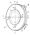
Independent illustrated base unit 18 is by insulating material in Fig. 3, and for example plastic material constitutes.It has the bottom 30 of the annular of being roughly, and is provided with cylindrical side wall 32 at the edge of bottom, has arranged that wherein four openings 34 and described four openings 34 are distributed on the circumference of base unit regularly.
According to two openings 34, be provided with bottom 30 global formations and radially be projected into permanent joint 36 outside the lateral wall 32 on 30 the plane, bottom.Be provided with the recess 38 that is arranged in the bottom and guarantees joint elastic at the edge of these joints side.
These joints are applicable to by bayonet socket and connect the base 100 base unit is installed to be used for admitting described switching device, and the protrusion end of joint 36 is received in the corresponding groove of base.
In order to ensure installing firm that elasticity connects on base, each joint 36 all comprises a protuberance 39 on the surface within it, and this protuberance is suitable for being received within the complementary recess that is arranged on the base.
The bottom 30 has otch 40, and the label that this otch is arranged on two other opening of sidewall 32 is in 42 the zone.
Elastic conduction lug plate 52A, 52B, 52C, 52D, 52E, 52F be from otch 40 extension that meets at right angles, and be projected into outside the outer surface of bottom 30.These conductive connection sheets are applicable to and switching device need not be welded to the circuit of printed circuit, and only press by simple pressure, and base unit is fixed, thereby guarantee to be electrically connected.
The elastic conduction lug plate only has the surface depression that can be electrically connected against the corresponding conductive connector of printed circuit by simple contact at its free end.
The conductive connection sheet is arranged along string triplets ground in otch 40 of cylindrical bottom portion 30.Each elastic conduction lug plate 52A, 52B, 52C, 52D are connected to conductive connector 56A, 56B, 56C, 56D by conducting wire 54A, 54B, 54C, 54D respectively.
These conductive connectors are arranged in the inner surface of bottom 30 and are arranged on foursquare four angles.
In addition, central conductive connection sheet 52E is connected to central conductive connector 56E by conducting wire 54E, and central conductive connector 56E is arranged in the place, foursquare diagonal crosspoint that is limited by conductive connector 56A, 56B, 56C, 56D.
At last, conductive connection sheet 52F is connected to the conductive region 56F that is arranged in bottom 30 inner surfaces by conducting wire 54F.This conductive region is an arc form, and this circular arc is 270 ° of extend throughs basically, and is the center with central conductive connector 56E, thereby can not consider the moving direction of control member, guarantees and the electrically contacting of public conductive member 28.
Form conducting wire 54A, 54B, 54C, 54D, 54E and 54F by conductive strips, these conductive strips can be pressed and the imbedding in the material that forms bottom 30 of part by reverse.
The assembly of conductive connection sheet, conducting wire, conductive connector and conductive region constitutes with same sheet metal, especially Dao Dian alloy sheet, for example stainless steel.This sheet be molded and forge and by cutting to obtain the form of expectation.
Behind the reverse press operation, the expose portion of conductive connection sheet, conducting wire, conductive connector and conductive region is coated or silver-plated.
In addition, in order at control member 14 to be the control member guiding when direction Z-Z moves, be provided with four through holes 58 that pass bottom 30 at foursquare four jiaos that with central conductive connector 56E are the center.These holes enlarge to form the centering profile gradually towards the inner surface of bottom.
Two holes extend through conducting wire 54E and 54F, and these conducting wires have the part of extending around the hole.
As shown in Fig. 2,4 and 5, public conductive member 28 is crossed the base plate 60 that is roughly the plane, and frame is on the inner surface of the bottom 30 of base unit.This base plate 60 has foursquare profile and is provided with four elastically deformable plate 62A, 62B, 62C, 62D at the edge, and these elastically deformable plates are in the homonymy bending of base plate, and defines the carriage 64 of the body 24 that is used to admit control member jointly.
These elastically deformable plates 62A is to 62D and base plate 60 global formations, and common partly elasticity is hinged to the side of square floor.
In more detail, base plate 60 is roughly the plane, and part has conduction vault 70 in the central, and this conduction vault stretches in the carriage 64, that is to say, leaves the bottom 30 of base unit.This conduction vault 70 extends facing to central conductive connector 56E substantially, and is suitable for strain and contacts with central conductive connector 56E up to it, guarantees electrical connection.
Static conduction vault 70 has customization height 0.35mm, and has approximately big 10 to 20 times diameter, and this diameter is 6mm like this.
The conduction vault 70 by the ring plain zone 72 of base plate 60 around, this plane domain 72 is supported by conductive region 56F.
Base plate 60 has four holes of aiming at hole 58 74 in its plane domain 72.
Four jiaos at base plate 60 are provided with V-notch 76, allow wherein at least two to admit link post 78, and link post 78 is outstanding with respect to the inner surface of the bottom 30 in joint 36 zones.These link posts 78 and bottom integrated moulding, and lean against on the two edges that limit otch 76, thus guarantee public conductive member 28 location and be fixed in the plane of bottom of base unit.
Each elastically deformable plate 62A, 62B, 62C, 62D are roughly the plane.They 79 are connected with the bottom in its end by cranking arm, and crank arm 79 to form the hair(-)pin that constitutes hinges.Radius of curvature is 0.1mm.These crank arm be the elastically deformable plate part and with base plate 60 global formations.
Each part of 79 of cranking arm is the continuous extension of the plane domain 72 of base unit, and the adjacent part of wherein cranking arm is the continuous extension of the elastically deformable plate of being correlated with.
Fully hinged for the formed hinge of bending area that allows to crank arm is provided with slit 80 on the inner surface of the bottom 30 of the base unit below each bending area of cranking arm.
Slit is roughly rectangular shape, and its length is greater than 79 the width of cranking arm of correspondence.They are suitable for being received in the part that constitutes the hinge of cranking arm during the strain of relevant elastically deformable plate.
Relative elastically deformable plate 62A, 62B, 62C, 62D assemble towards its free end each other.
In inactive state, each elastically deformable plate 62A extends above base plate 60 and substantially limits 55 ° angle with base plate 60 to 62D.
The free margins 81 of each the elastically deformable plate relative with base plate 60 is towards the outer surface slight bending of carriage 64, with the limit on the body 24 that is formed for being supported on control member.
In addition, each elastically deformable plate 62A, 62B, 62C, 62D partly have conductive contact 82A, 82B, 82C, 82D, these conductive contacts and relevant moulding of elastically deformable slab integral and elastically deformable in the central.Each conductive contact 82A, 82B, 82C, 82D are with respect to the outer surface bending of relevant elastically deformable plate towards carriage 64.The curved end that forms the conductive contact of movable conductive finger 83A, 83B, 83C, 83D defines an angle that is approximately 100 ° together with relevant elastically deformable plate.Conductive contact is substantially according to the hinge axes bending of the elastically deformable plate 62A parallel with the face of base plate 60,62B, 62C, 62D.
Public conductive member 28 is made of same rustproof spring steel plate, and this rustproof spring steel plate thickness is about 50 μ m, and be cut, moulding, coated then or silver-plated.
As shown in each accompanying drawing, each movable conductive finger substantially with relevant conductive connector 56A, 56B, 56C, the 56D extension that meets at right angles.
In the inactive state as shown in Fig. 2 and 4, movable conductive finger 83A, 83B, 83C, 83D leave relevant conductive connector and define with conductive connector and be about 25 ° angle.
The body 24 of control member is introduced separately in Fig. 6.It typically is the form of parallelepipedon post.Its external dimensions is slightly larger than the external dimensions of the carriage 64 that is limited by elastically deformable plate 62A, 62B, 62C, 62D, and body can not have being fixed of play and is positioned at central resting position between elastically deformable plate 62A, 62B, 62C, 62D like this.Body 24 is received within the carriage 64 between the elastically deformable plate, and the elastically deformable plate is supported on side 90A, 90B, 90C, the 90D of body.In these sides each all has center cutout 91, thereby the elastically deformable plate only is pressed in the outside of body side along its free margins 81, therefore allows the reversing of elastically deformable plate 62A, 62B, 62C, 62D of part in the central.
The bottom surface label of body is 92, has a ring-type bowl chamber 94 at the middle body of body 24, and this bowl chamber defines a binding post 96 at middle position, the top that is used to push elastic conduction vault 70, and simultaneously, body keeps in touch to press at another side and covers 20.The diameter of binding post 96 is approximately half of conduction vault diameter, that is to say, be approximately 3mm, so that the select location of unattended operation member or resting position, binding post 96 is pressed in the lasting contact in top of vault 70 of guaranteeing to conduct electricity, and covers 20 thereby keep body 24 to press.
In addition, four pins 98 are outstanding from the bottom surface 92 of body 24.They have periphery centering chamfering at its top.These pins are applicable to when depressing control member, are received in the hole 58 of base unit.
As shown in Figure 2, body 24 surface thereon is provided with a space 102, and the ledge 104 of button 26 is force-fitted in wherein, and this part is provided with a ring-type retaining part.Button is rotarily formed usually, and is that 106 exposed surface has a reception groove 108 that is used for the finger manipulation device at its label.This groove 108 is provided with the non skid matting state, helicla flute for example, and the coating of polymer can be set, for example polyurethane.
This groove 108 is provided with a retainer 110 at its edge, this retainer exceeds the periphery in hole 22, has laterally increased button Face.The external diameter of button is 11mm.
Button 26 in height reaches outside the housing 12, but should be highly much smaller than its diameter.This highly is decided to be 1mm, when pressing the button, allows moving both vertically of about 0.35mm.
Be understandable that body 24 is along can translational motion perpendicular to all directions of direction Z-Z, the elastic reaction by conduction vault 70 is held pressing and covers 20 simultaneously.
The elastically deformable plate on four planes (wherein two boards is parallel with other two boards) has reduced the possibility of control member 14 around its vertical axis rotation with the form that is arranged on the side combination on the body 24, in inactive state, make button turn back to its initial state simultaneously.
According to first specific embodiment, hole 22 is round, allows onesize control member 14 along moving perpendicular to all directions of direction Z-Z.
When the control member transverse movement, as shown in Figure 7, one or two elastically deformable plate, for example elastically deformable plate 62B strain and by by outward-dipping and aligned with respect to base plate 60 causes the relevant movable conductive finger 83B that tilts to reduce.This movable conductive finger contacts with following conductive connector 56B then, thereby guarantees being electrically connected between corresponding conductive connector 56B and the public conductive member 28.
When conductive connector 56B is connected to conductive connection sheet 52B, upward base plate 60 is connected on the conductive connection sheet 52F by being supported on conductive region 56F simultaneously, at this moment, between conductive connection sheet 52B and 52F, produce electrical connection.
When releasing operation member 14, control member is driven by the elastically deformable plate of initial deformation, thereby turns back to its resting position, as shown in Figure 2.In this position, do not produce electrical connection, all movable conductive fingers are removed from relevant conductive connector.
Activity at four elastically deformable plates of the horizontal plane surface of control member body allows control member to turn back to its original position with respect to housing on the one hand, turns back to its initial orientation on the other hand, especially with respect to the position, angle about direction Z-Z.
Be understandable that, control member 14 is perpendicular to the motion on one of them direction of two main direction X-X, the Y-Y of direction Z-Z, make conductive connection sheet 52F be connected among conductive connector 56A, 56B, 56C, the 56D at least one, thereby conductive connection sheet 52F is communicated with one of them terminals 52A, 52B, 52C, 52D by public conductive member 28.
During sliding on principal direction X-X or the Y-Y, the free margins 81 that is in substantially parallel relationship to the elastically deformable plate that moving direction extends is the body 24 of pilot operationp member laterally in both sides.In order to produce the switch effect, the stroke of control member on principal direction is approximately 0.8mm.
Further, at control member 14 when a foursquare diagonal that is limited by elastically deformable plate 62A, 62B, 62C, 62D moves, that is to say, when moving with respect to principal direction X-X and Y-Y direction at 45, two adjacent elastically deformable plates flexibly are out of shape and are outwards stressed, cause movable conductive finger to contact simultaneously with relevant conductive connector, this has guaranteed that conductive connection sheet 52F is communicated with two conductive connection sheets corresponding to conductive connector, makes movable conductive finger press conductive connector.
In this way, choice device has formed one and has had eight selectors of selecting paths and to confirm the path.
At last, when control member 14 during in its resting position, as shown in Figure 2, pin 98 58 is arranged towards the hole, thereby is allowed by control member 14 being pressed into housing 12 control member 14 to be moved along direction Z-Z.The chamfering that is located at the pin periphery is beneficial to its joint and aligning enters hole 58, and described Kong Zaiqi end is opened promptly in the bottom 30 inner surface outward and opened.
When depressing control member 14, conduction vault 70 strains, thus its middle body presses central conductive connector 56E by binding post 96, has guaranteed that thus conductive connection sheet 52F and 52E are communicated with by public conductive member 28.
The shape of known conduction vault is suitable for, power according to deformation extent distortion institute palpus is non-linear like this, particularly, in the development of this power, have the appreciable local minimum of a user, guarantee that a haptic effect informs that the user correctly depresses control member and electric switch.As is known, when realizing electrically contacting, the pressure that produces haptic effect changes.
The pin 98 and the existence of complimentary aperture 58 have been guaranteed to have only when control member during in its resting position, depress control member, central conductive connector 56E are communicated with, as shown in Figure 2 with public conductive member 28.
It should be noted,, the centering of control member is acted on, guaranteed the direction Z-Z translation of guiding along control member by elastically deformable plate 62A, 62B, 62C, 62D in this position.
As a modification, can sell without these, thereby not consider the position of control member, allow to depress control member, and therefore confirm.
According to another embodiment, switching device is suitable for allowing conductive connection sheet 52F only to be communicated with single conductive connector 56A, 56B, 56C, 56D at every turn, and this device forms and has four selectors of selecting a path and an affirmation path like this.
For this reason, as shown in Figure 8, label is that 120 case lid has a hole 122, and it makes the shape of restriction control member in the motion of some direction.Particularly, hole 122 is roughly the trilobal with four recess 122A, 122B, 122C, 122D, these recess are arranged on basic exercise direction X-X and the Y-Y, protuberance 124A, the 124B, 124C, the 124D that form retainer are arranged between the recess, move with respect to basic orientation X-X and Y-Y direction at 45 with restriction control member 14 edges.
When using this switching device, the motion of the translation that control member and housing bottom are parallel had both made movable conductive finger 83A, 83B, 83C, 83D very rapidly be connected to corresponding conductive connector, also made the relevant conductive connector of the very fast disengaging of movable conductive finger.So, switching device can be used for carrying out the very fast control of portable electron device, especially at games section (games sector).This device is especially favourable for the games (arcadegames) of game center.
Also promptly to chosen position moving switch device, the upper surface of available finger alternating movement contact button is pointed along a direction movable button for continuously, and returns when pointing, and when promptly breaking away from button slightly, allows button to return its resting position automatically.
User finger this alternately touches motion and can be very easy to realize that continuous selections in a large number can be very rapidly carried out in the slip of control member like this.
In addition, the use of single member has guaranteed the fexible bias pressure of five contacts, control member 14 resting position on its translation and its position, angle and the guiding of this control member simultaneously, make it possible to obtain switching device, only use parts can guarantee the guiding of five contacts and five resiliency urged effects and control member with low cost.
At last, the translational motion of control member 14 with the extension that is positioned at control member 14, hinged movable conductive finger 83A, 83B, 83C, motion that 83D is relevant, makes the housing height reduce greatly specifically.
In the described here device, control member 14 causes the closure of associated contacts towards the motion of a chosen position.As a modification, when control member remains static, junction closure, and control member causes the disconnection of associated contacts when a chosen position moves.
Fig. 9 illustrates the base 100 that is used to admit switching device according to of the present invention.
For example, this base can be formed on the shell of a portable electric appts, and switching device is combined in the base.For example, can be the upper surface of mobile phone.So, base is limited in the wall 102 of plastic material.This base comprise one be used to admit switching device body be roughly columniform path 10 4.This passage has the height that the height corresponding to housing 12 reduces basically.Have two spiral ridges 106 in its bottom, described fin is with respect to the axis symmetry of passage.Described fin is 120 ° of extend throughs basically, and define two through holes 108 that are used for fixing joint 36 together, and described permanent joint extends radially the lateral surface of housing.
Fin 106 108 has gradually the thickness that increases to its other end from the hole, to form the inclined-plane that maintains joint 36 by wedge.Further on the fin 106 relative, provide retainer 110 to limit the location of switching device with hole 108.May further be each fin a complementary recess that is suitable for admitting protuberance 39 is provided, to guarantee that joint 36 is flexibly joined in the base.
As shown in figure 10, be understandable that switching device is combined in the base 100 that is positioned at the electronic equipment outer surface.Particularly, joint 36 engages with hole 108.
This device is around 40 ° of himself rotations then, thereby joint 36 engages with following fin 106, engages with complementary recess against retainer 110 and protuberance 39 up to joint.
This device is located as shown in figure 10 then, arranges and resilient engagement by the bayonet socket that is located at protuberance on joint and the fin and complementary recess, and device is fixed on above-mentioned position.So when fit walls 102 and printed circuit, conductive connection sheet 52A, 52B, 52C, 52D, 52F are connected with the printed circuit of electronic equipment.
Be understandable that,, thereby make switching device with respect to base centering because base has and be roughly the cylinder axis that columniform switching device is connected and have the bayonet socket holding device.Particularly, at the outer surface of electronic equipment, switching device can accurately be fitted, and makes can not produce any attractive slit between the housing of equipment of switching device and global formation.Do not prevent the dust that electronic equipment is inside and outside thereby there is the slit to seal, and " sealing " is positioned at the light that electroluminescent diode sent on the switching device printed circuit nearby.