JP4446925B2 - Slide operation switch - Google Patents
Slide operation switch Download PDFInfo
- Publication number
- JP4446925B2 JP4446925B2 JP2005133129A JP2005133129A JP4446925B2 JP 4446925 B2 JP4446925 B2 JP 4446925B2 JP 2005133129 A JP2005133129 A JP 2005133129A JP 2005133129 A JP2005133129 A JP 2005133129A JP 4446925 B2 JP4446925 B2 JP 4446925B2
- Authority
- JP
- Japan
- Prior art keywords
- slide
- electrode pair
- conductor
- case
- back wall
- Prior art date
- Legal status (The legal status is an assumption and is not a legal conclusion. Google has not performed a legal analysis and makes no representation as to the accuracy of the status listed.)
- Expired - Fee Related
Links
Images


Classifications
-
- E—FIXED CONSTRUCTIONS
- E03—WATER SUPPLY; SEWERAGE
- E03C—DOMESTIC PLUMBING INSTALLATIONS FOR FRESH WATER OR WASTE WATER; SINKS
- E03C1/00—Domestic plumbing installations for fresh water or waste water; Sinks
- E03C1/02—Plumbing installations for fresh water
- E03C1/04—Water-basin installations specially adapted to wash-basins or baths
-
- H—ELECTRICITY
- H01—ELECTRIC ELEMENTS
- H01H—ELECTRIC SWITCHES; RELAYS; SELECTORS; EMERGENCY PROTECTIVE DEVICES
- H01H25/00—Switches with compound movement of handle or other operating part
- H01H25/002—Switches with compound movement of handle or other operating part having an operating member rectilinearly slidable in different directions
-
- E—FIXED CONSTRUCTIONS
- E03—WATER SUPPLY; SEWERAGE
- E03C—DOMESTIC PLUMBING INSTALLATIONS FOR FRESH WATER OR WASTE WATER; SINKS
- E03C1/00—Domestic plumbing installations for fresh water or waste water; Sinks
- E03C1/02—Plumbing installations for fresh water
- E03C1/04—Water-basin installations specially adapted to wash-basins or baths
- E03C2001/0414—Water-basin installations specially adapted to wash-basins or baths allowing different orientations of the spout or the outlet nozzle
-
- H—ELECTRICITY
- H01—ELECTRIC ELEMENTS
- H01H—ELECTRIC SWITCHES; RELAYS; SELECTORS; EMERGENCY PROTECTIVE DEVICES
- H01H15/00—Switches having rectilinearly-movable operating part or parts adapted for actuation in opposite directions, e.g. slide switch
- H01H15/005—Switches having rectilinearly-movable operating part or parts adapted for actuation in opposite directions, e.g. slide switch adapted for connection with printed circuit boards
-
- H—ELECTRICITY
- H01—ELECTRIC ELEMENTS
- H01H—ELECTRIC SWITCHES; RELAYS; SELECTORS; EMERGENCY PROTECTIVE DEVICES
- H01H15/00—Switches having rectilinearly-movable operating part or parts adapted for actuation in opposite directions, e.g. slide switch
- H01H15/02—Details
- H01H15/06—Movable parts; Contacts mounted thereon
- H01H15/10—Operating parts
- H01H15/102—Operating parts comprising cam devices
-
- H—ELECTRICITY
- H01—ELECTRIC ELEMENTS
- H01H—ELECTRIC SWITCHES; RELAYS; SELECTORS; EMERGENCY PROTECTIVE DEVICES
- H01H25/00—Switches with compound movement of handle or other operating part
- H01H25/002—Switches with compound movement of handle or other operating part having an operating member rectilinearly slidable in different directions
- H01H2025/004—Switches with compound movement of handle or other operating part having an operating member rectilinearly slidable in different directions the operating member being depressable perpendicular to the other directions
-
- H—ELECTRICITY
- H01—ELECTRIC ELEMENTS
- H01H—ELECTRIC SWITCHES; RELAYS; SELECTORS; EMERGENCY PROTECTIVE DEVICES
- H01H2227/00—Dimensions; Characteristics
- H01H2227/036—Minimise height
Description
本発明は、ケースに対してスライド移動自在に収められたスライド部材と、このスライド部材を中立位置に付勢する付勢部材と、この付勢部材の付勢力に抗して前記スライド部材を操作した際に電気的な導通状態を生じるスライド操作式スイッチに関する。また、さらにこのスライド部材を押し込み操作した際にも電気的な導通状態を生じる多接点のスライド操作式スイッチに関する。 The present invention relates to a slide member housed slidably with respect to a case, a biasing member that biases the slide member to a neutral position, and operates the slide member against the biasing force of the biasing member The present invention relates to a slide operation type switch that generates an electrical continuity when it is operated. Further, the present invention relates to a multi-contact slide operation type switch that generates an electrical conduction state even when the slide member is pushed.
上記のようなスライド操作式スイッチとして、下記に示す特許文献1には操作部材の押し込み動作を通じて動作される第1スイッチと操作部材の揺動動作を通じて動作される複数の第2スイッチとを備えた多接点入力装置の発明が記載されている。
この第1スイッチは、操作部材の押し込み動作により金属ドームを押圧し、これにより生じるスナップ動作を通じて開閉されるものである。第2スイッチは、第1スイッチから等間隔を隔てた周囲の複数箇所に配備され、操作部材の揺動動作によりアーチ状のスナップ板を押圧し、これにより生じるスナップ動作を通じて開閉されるものである。
特許文献1には好適な実施形態としては、第1スイッチを中心に備え、第1スイッチから等間隔を隔てた周囲にそれぞれ90度ずつ離れて4つの第2スイッチを備える構成が示されている。操作部材の揺動により、1つの第2スイッチを開閉するが、同時に2つの第2スイッチを開閉操作することがないように突起を設けて一定の方向への揺動の移動量を規制している。
As a slide operation type switch as described above,
The first switch presses the metal dome by the pushing operation of the operation member, and is opened and closed through a snap operation generated thereby. The second switch is disposed at a plurality of locations around the first switch at equal intervals, presses the arched snap plate by the swinging motion of the operation member, and is opened and closed through the resulting snap motion. .
また、下記に示す特許文献2には、スライド部材を中立位置に付勢する付勢部材の付勢力に抗してスライド部材を操作した際に電気的な導通状態を生じるスライド操作式スイッチの発明が記載されている。
付勢部材は、正方形状のスライド部材の周壁部を嵌め込み支持する正方形の開口を形成した保持部を有してスライド部材を中立位置に付勢する。付勢部材が収納されるケースは、スライド部材よりも大きい正方形状の底壁とこの底壁の周囲を取り囲む状態で底壁から立ち上がる壁部を有している。付勢部材は、この壁部の角部に向けて正方形状の開口部の角部から突設した突出部を有している。この突出部は開口部の角部から突出部の形成方向に向かって切り開いた状態となるスリットを形成している。スライド部材をスライドさせるとスリットが開き、付勢部材の開口の外側に設けたられた導電体がケースの壁部に設けられた対となる電極間を導通させる。
また、特許文献2には、さらにこのスライド部材を押し込み操作した際にも電気的な導通状態を生じる多接点のスライド操作式スイッチの発明が記載されている。
Further, in
The urging member has a holding portion formed with a square opening for fitting and supporting the peripheral wall portion of the square slide member, and urges the slide member to the neutral position. The case in which the urging member is accommodated has a square bottom wall that is larger than the slide member and a wall portion that rises from the bottom wall so as to surround the bottom wall. The urging member has a protruding portion that protrudes from the corner of the square opening toward the corner of the wall. This protrusion forms a slit that is open from the corner of the opening toward the direction in which the protrusion is formed. When the slide member is slid, the slit opens, and a conductor provided outside the opening of the biasing member conducts between the pair of electrodes provided on the wall portion of the case.
Further,
特許文献1にスイッチでは、周辺部の4つの第2スイッチを操作部材の揺動操作により開閉するため、操作部材を押して傾けるという動作を伴う。第2スイッチの複数が同時に入力されることを想定して操作部材を規制する機構は備えているが、第1スイッチと第2スイッチとが同時に入力される可能性は完全には排除されていない。
In the switch disclosed in
特許文献2のスイッチは、周辺部のスイッチはスライド部材のスライド操作で開閉し、中心部のスイッチはスライド部材の押し込み操作で開閉する。両スイッチを操作する動作が異なるため、両スイッチが同時に入力される可能性は特許文献1の構成よりも低くなる。また、特許文献1の4つのスナップ板に対し、特許文献2では1つの付勢部材を利用して周辺部のスライドスイッチを開閉する。従って、特許文献2のスイッチは、より少ない部品点数で構成できる。しかし、特許文献2のスイッチは、スライド方式のスイッチだけを有する場合には薄く構成できる(特許文献2第3図参照)が、押し込み操作した場合のスイッチも有するとその分だけ厚みを増す構成となる(特許文献2第10図参照)。つまり、スライド方式のスイッチの下部に中間作動部材(特許文献2第10図符号15参照)を備え、この中間作動部材のさらに下部に押し込み操作した場合のスイッチを有する構造である。従って、スイッチ全体の厚みが増し、中間作動部材を必要とする分、部品点数の増化を招く。
In the switch of
本願発明は上記課題に鑑みてなされたもので、部品点数が少なく、薄型に構成可能なスライド操作式スイッチを提供することを目的とする。 The present invention has been made in view of the above problems, and an object of the present invention is to provide a slide operation type switch that has a small number of parts and can be configured to be thin.
この目的を達成するための本発明に係るスライド操作式スイッチの特徴構成は、ケースに対してスライド移動自在に収められたスライド部材と、このスライド部材を中立位置に付勢する付勢部材と、この付勢部材の付勢力に抗して前記スライド部材を操作した際に電気的な導通状態を生じるスライド操作式スイッチであって、
前記ケースを、底部に少なくとも1対の電極対を備えて構成し、前記付勢部材を、前記スライド移動方向に沿う平坦な床部から前記スライド部材に対して前記スライド移動方向で対向する横側に立ち上がり当該スライド部材を前記中立位置に付勢する背壁部と、この背壁部の前記スライド部材の存在側とは反対側に備えられた導電体と、前記背壁部の両端の側壁部と、前記背壁部及び前記側壁部に支持される天井部とを有する突出部を備えて構成し、前記付勢部材は、前記スライド移動方向に直交する方向から前記底部に重ねてあり、前記スライド部材が付勢力に抗して前記突出部の方向へ操作された場合には、この突出部が弾性変形して前記背壁部が前記ケースの底部に向けて倒れることにより、前記導電体を介して前記電極対の各電極同士が導通する点にある。
In order to achieve this object, the characteristic configuration of the slide operation type switch according to the present invention includes a slide member that is slidably moved with respect to the case, a biasing member that biases the slide member to a neutral position, A slide operation type switch that generates an electrically conductive state when the slide member is operated against the biasing force of the biasing member,
The case is configured by including at least one pair of electrodes on the bottom, and the biasing member is opposed to the slide member in the slide movement direction from a flat floor portion along the slide movement direction. A back wall portion that rises to urge the slide member to the neutral position, a conductor provided on a side of the back wall portion opposite to the side where the slide member exists, and side wall portions at both ends of the back wall portion And a projecting part having a ceiling part supported by the back wall part and the side wall part, and the biasing member is superimposed on the bottom part from a direction orthogonal to the sliding movement direction, When the slide member is operated in the direction of the protrusion against the urging force, the protrusion is elastically deformed and the back wall portion falls toward the bottom of the case, thereby Each electrode of the electrode pair But there is a point to conduct.
この特徴構成によれば、付勢部材に突出部を備え、この突出部が有する背壁によってスライド部材を中立位置に付勢する。そして、スライド部材が付勢力に抗して突出部の方向へ操作されると、突出部が弾性変形する。突出部の背壁とは反対側には導電体が備えられており、突出部の弾性変形に伴ってこの導電体がケースの底部に備えられた電極対の各電極同士を導通させる。このように電極対を導通させる導電体が付勢部材に一体化されているため、少ない部品点数でスライド操作式スイッチを構成することができる。
上述した特許文献2の構成においても付勢部材に導電体を備えているが、電極はケースの底から立ち上がる壁面に備えられている。このため、電極の高さ分の壁面がケースに必要となり、これがスライド操作式スイッチの薄型化の限界となる。本発明の構成では、電極対がケースの底部に備えられるため、ケースの壁面は電極に依存されず、薄型化が容易となる。
このように本特徴構成によれば、部品点数が少なく、薄型に構成可能はスライド操作式スイッチを得ることができる。
According to this characteristic configuration, the biasing member is provided with the protruding portion, and the slide member is biased to the neutral position by the back wall of the protruding portion. When the slide member is operated in the direction of the protrusion against the urging force, the protrusion is elastically deformed. A conductor is provided on the side opposite to the back wall of the protrusion, and the conductor conducts the electrodes of the electrode pair provided at the bottom of the case with the elastic deformation of the protrusion. Thus, since the conductor which makes an electrode pair conduct | electrically_connected is integrated with the biasing member, a slide operation type switch can be comprised with few components.
In the configuration of
As described above, according to this characteristic configuration, a slide operation type switch can be obtained that has a small number of parts and can be configured thinly.
また、前記電極対及び前記突出部を、方形状の前記ケースの前記底部の四方の外周側にそれぞれ備え、前記付勢力に抗して前記スライド部材が何れか一つ又は二つの前記突出部の方向へ操作された場合は、当該一つ又は二つの突出部が有する前記導電体を介して前記電極対の各電極同士が導通するものであると好適である。 In addition, the electrode pair and the protruding portion are provided on each of the four outer peripheral sides of the bottom portion of the rectangular case, and the slide member has one or two protruding portions against the urging force. When operated in the direction, it is preferable that the electrodes of the electrode pair are electrically connected to each other through the conductors of the one or two projecting portions.
電極対を方形状のケースの底部の四方の外周側にそれぞれ備え、突出部を方形状の付勢部材の四方の外周にそれぞれ備えて構成すると、それぞれの突出部の背壁は方形状の付勢部材の中心に向いて互いに対向する。そして、ケースや付勢部材と相似形の方形状に構成されたスライド部材は、その四方を4つの背壁部によって良好に支持される。その結果、スライド部材は良好に中立位置に付勢され、多数の接点を有するスライド操作式スイッチを得ることができる。 If the electrode pair is provided on each of the four outer peripheral sides of the bottom of the square case and the protrusion is provided on each of the four outer periphery of the square biasing member, the back wall of each protrusion is attached to the square shape. It faces each other toward the center of the biasing member. And the slide member comprised in the square shape similar to a case or an urging | biasing member is favorably supported by the four back wall parts on the four sides. As a result, the slide member is favorably biased to the neutral position, and a slide operation type switch having a large number of contacts can be obtained.
また、本発明に係るスライド操作式スイッチの別の特徴構成は、ケースに対してスライド移動自在に収められたスライド部材と、このスライド部材を中立位置に付勢する付勢部材と、この付勢部材の付勢力に抗して前記スライド部材を操作した際に電気的な導通状態を生じるスライド操作式スイッチであって、
前記ケースを、底部に少なくとも1対の第一電極対と、1対の第二電極対とを備えて構成し、前記付勢部材を、前記スライド移動方向に沿う平坦な床部から前記スライド部材に対して前記スライド移動方向で対向する横側に立ち上がり前記スライド部材を前記中立位置に付勢する背壁部と、この背壁部の前記スライド部材の存在側とは反対側に備えられた第一導電体と、前記背壁部の両端の側壁部と、前記背壁部及び前記側壁部に支持される天井部とを有する突出部を備えて構成すると共に、前記床部の前記スライド部材の存在側とは反対側に第二導電体を備え、
前記付勢部材は、前記スライド移動方向に直交する方向から前記底部に重ねてあり、
前記スライド部材が付勢力に抗して前記突出部の方向へ操作された場合には、この突出部が弾性変形して前記背壁部が前記ケースの底部に向けて倒れることにより、前記第一導電体を介して前記第一電極対の各電極同士が導通し、前記スライド部材が前記中立位置において前記床部の方向に押圧された場合には、前記第二導電体を介して前記第二電極対の各電極同士が導通する点にある。
Further, another characteristic configuration of the slide operation type switch according to the present invention includes a slide member that is slidably moved with respect to the case, a biasing member that biases the slide member to a neutral position, and the biasing A slide operation type switch that generates an electrical continuity when the slide member is operated against the biasing force of the member,
The case is configured to include at least one first electrode pair and one second electrode pair at the bottom, and the urging member is moved from the flat floor along the sliding movement direction to the slide member. A back wall portion that rises laterally opposite to the slide movement direction and biases the slide member to the neutral position, and a back wall portion that is provided on a side opposite to the slide member existing side . And a projecting portion having a conductor , a side wall portion at both ends of the back wall portion, and a ceiling portion supported by the back wall portion and the side wall portion, and the slide member of the floor portion. A second conductor is provided on the side opposite to the existence side ,
The biasing member is stacked on the bottom from a direction orthogonal to the sliding movement direction,
When the slide member is operated in the direction of the protrusion against the urging force, the protrusion is elastically deformed, and the back wall portion falls toward the bottom of the case, so that the first When the electrodes of the first electrode pair are electrically connected to each other through the conductor, and the slide member is pressed toward the floor portion at the neutral position, the second electrode is interposed through the second conductor. The point is that the electrodes of the electrode pair are electrically connected.
この特徴構成によれば、付勢部材に突出部を備え、この突出部が有する背壁によってスライド部材を中立位置に付勢する。そして、スライド部材が付勢力に抗して突出部の方向へ操作されると、突出部が弾性変形する。突出部の背壁とは反対側には第一導電体が備えられており、突出部の弾性変形に伴ってこの第一導電体がケースの底部に備えられた第一電極対の各電極同士を導通させる。さらに、スライド部材が中立位置において付勢部材の床部方向に押圧された場合は、第二導電体が前記第二電極対の各電極対同士を導通させる。このように少なくとも第一電極対を導通させる第一導電体が付勢部材に一体化されており、第二導電体は別部品であっても1つの部品であるため、少ない部品点数でスライド操作式スイッチを構成することができる。もちろん、第二導電体が付勢部材の他方の面の側に一体化されていれば、さらに少ない部品点数で構成することができる。 According to this characteristic configuration, the biasing member is provided with the protruding portion, and the slide member is biased to the neutral position by the back wall of the protruding portion. When the slide member is operated in the direction of the protrusion against the urging force, the protrusion is elastically deformed. A first conductor is provided on the opposite side of the back wall of the protrusion, and each electrode of the first electrode pair provided on the bottom of the case with the first conductor is elastically deformed of the protrusion. Is made conductive. Furthermore, when the slide member is pressed toward the floor of the biasing member at the neutral position, the second conductor makes the electrode pairs of the second electrode pair conductive. In this way, the first conductor for conducting at least the first electrode pair is integrated with the biasing member, and the second conductor is a single component even if it is a separate component, so the slide operation can be performed with a small number of components. A type switch can be constructed. Of course, if the second conductor is integrated on the other side of the urging member, the number of parts can be reduced.
上述した特許文献2の構成においても付勢部材に第一導電体に相当する導電体を備えている。しかし、第一導電体に相当する導電体はケースの底から立ち上がる壁面に備えられており、第一導電体に相当する導電体の高さ分の壁面がケースに必要となる。これはスライド操作式スイッチの薄型化の限界となる。
また、特許文献2の構成では付勢部材が環状に構成されており、中立位置に付勢されたスライド部材の下方(ケースの方向)には付勢部材が存在しない。このため、第二導電体を付勢部材と一体化することはできない。さらに、第一導電体と第一電極対とによるスライド操作式スイッチの下部に、第二導電体と第二電極対とを備えた2階建て構造となって薄型化の妨げとなっている。また、この2階建て構造に起因して、第二導電体に相当する導電体と付勢部材との間には中間作動部材を必要している。
本発明の構成では、第一電極対及び第二電極対が共に同じケースの底部に備えられるため、ケースの壁面は電極に依存されず、薄型化が容易となる。また、スライド操作によるスイッチと押し込み操作によるスイッチとを2階建て構造にしたものではなく、一層構造であるので、良好に薄型化が図れる。中間作動部材も必要としないので、より少ない部品点数でスライド操作式スイッチを得ることができる。
このように本特徴構成によれば、部品点数が少なく、薄型に構成可能なスライド操作式スイッチを得ることができる。
Also in the configuration of
Moreover, in the structure of
In the configuration of the present invention, since the first electrode pair and the second electrode pair are both provided at the bottom of the same case, the wall surface of the case does not depend on the electrode and can be easily reduced in thickness. In addition, the switch by the slide operation and the switch by the push-in operation are not a two-story structure, but a one-layer structure, so that the thickness can be reduced favorably. Since no intermediate actuating member is required, a slide operation type switch can be obtained with a smaller number of parts.
As described above, according to this characteristic configuration, it is possible to obtain a slide operation type switch that has a small number of parts and can be configured to be thin.
また、前記第一電極対及び前記突出部を、方形状の前記ケースの前記底部の四方の外周側にそれぞれ備え、前記付勢力に抗して前記スライド部材が何れか一つ又は二つの前記突出部の方向へ操作された場合は、当該一つ又は二つの突出部が有する前記第一導電体を介して前記第一電極対の各電極同士が導通するものであると好適である。 Further, the first electrode pair and the projecting portion are provided on each of the four outer peripheral sides of the bottom portion of the square case, and either one or two of the projecting members resist the biasing force. When operated in the direction of the portion, it is preferable that the electrodes of the first electrode pair are electrically connected to each other through the first conductor included in the one or two protruding portions.
第一電極対を方形状のケースの底部の四方の外周側にそれぞれ備え、突出部を方形状の付勢部材の四方の外周にそれぞれ備えて構成すると、それぞれの突出部の背壁は方形状の付勢部材の中心に向いて互いに対向する。好適にはケースや付勢部材と相似形の方形状に構成されたスライド部材は、その四方を4つの背壁によって良好に支持される。その結果、スライド部材は良好に中立位置に付勢される。スライド部材は、方形状の付勢部材の中心部を中立位置とするので、この中立位置の下部に位置する第二電極対及び第二導電体との位置決め精度を向上することができる。 When the first electrode pair is provided on each of the four outer peripheral sides of the bottom of the rectangular case and the protrusion is provided on each of the four outer periphery of the square biasing member, the back wall of each protrusion is rectangular. The two biasing members face each other toward the center. The slide member preferably formed in a square shape similar to the case or the biasing member is favorably supported by the four back walls on all four sides. As a result, the slide member is favorably biased to the neutral position. Since the slide member has the central portion of the square-shaped urging member as the neutral position, the positioning accuracy of the second electrode pair and the second conductor located at the lower portion of the neutral position can be improved.
ここで、前記第二電極対を同心円状に構成し、前記第二導電体を金属ドームで構成すると好適である。 Here, it is preferable that the second electrode pair is formed concentrically and the second conductor is formed of a metal dome.
上述したように、突出部を方形状の付勢部材の四方の外周にそれぞれ備えて構成すると、それぞれの突出部の背壁部は方形状の付勢部材の中心に向いて互いに対向する。スライド部材は、方形状の付勢部材の中心部を中立位置とする。従って方形状の付勢部材の中心部を中心とする同心円状に第二電極対を構成すると、四方に備えられた第一電極対の全てと均等な位置に第二電極対を設けることができる。その結果、スライド操作によるスイッチと押し込み操作によるスイッチとの両機能を安定して発揮することのできるスライド操作式スイッチを得ることができる。
この同心円状の第二電極対を導通させる第二導電体を金属ドームで構成すると、同心円状の外側の第二電極は常に第二導電体と接触し、押し込み操作に従って同心円状の内側の第二電極を第二導電体に接触させることができる。その結果、押し込み方向に偏りが生じた場合でも良好に第二電極対を導通させることができる。また、金属ドームの中央部を押し込み操作によってへこませ、押し込み操作の解除にともなって復帰させるので、押し込み操作によるクリック感を操作者に与えることができる。
As described above, when the protrusions are provided on the four outer circumferences of the square biasing member, the back wall portions of the protrusions face each other toward the center of the square biasing member. The slide member has a neutral position at the center of the square biasing member. Therefore, when the second electrode pair is formed concentrically with the central portion of the square-shaped biasing member as the center, the second electrode pair can be provided at a position equivalent to all of the first electrode pairs provided in the four directions. . As a result, it is possible to obtain a slide operation type switch that can stably exhibit both functions of the switch by the slide operation and the switch by the push operation.
When the second conductor for conducting the concentric second electrode pair is formed of a metal dome, the second electrode on the outer side of the concentric circle always contacts the second conductor, and the second inner electrode on the inner side of the concentric circle follows the pushing operation. The electrode can be in contact with the second conductor. As a result, the second electrode pair can be conducted well even when a deviation occurs in the pushing direction. Further, since the center portion of the metal dome is depressed by the pushing operation and is restored when the pushing operation is released, a feeling of clicking by the pushing operation can be given to the operator.
また、前記第二電極対の外周に前記金属ドームを規制する複数の突起を有すると好適である。 In addition, it is preferable that a plurality of protrusions for restricting the metal dome are provided on the outer periphery of the second electrode pair.
第二導電体を別部品である金属ドームで構成する場合、金属ドームが所定の位置からずれる可能性がある。しかし、上記のように第二電極対の外周に金属ドームを規制するための突起を設けると、このずれを抑制することができて好ましい。 When the second conductor is formed of a metal dome that is a separate part, the metal dome may be displaced from a predetermined position. However, it is preferable to provide a protrusion for restricting the metal dome on the outer periphery of the second electrode pair as described above because this deviation can be suppressed.
以下、本発明の実施例を図面に基づいて説明する。図1は、本発明に係るスライド操作式スイッチの分解斜視図である。図1に示すようにケース1、金属ドーム2、付勢部材3、シート4、スライダー5、カバー6、キートップ7を順次重ね合わせてスライド操作式スイッチを構成する。
Embodiments of the present invention will be described below with reference to the drawings. FIG. 1 is an exploded perspective view of a slide operation type switch according to the present invention. As shown in FIG. 1, the
ケース1は、例えばLCP樹脂(液晶ポリエステル樹脂)などを用いて成形されるものである。LCP樹脂は、耐熱性と成形性に優れた樹脂材料である。近年、環境問題に鑑みて鉛フリー半田の導入が急速に進んでいるが、一般に鉛フリー半田は鉛を含有する半田に比べて融点が高い。そのため、電子部品を基板に半田付けする際のリフロー温度を従来よりも摂氏10〜25度程度高温にする必要が生じる。その影響により、コネクタやスイッチといった成形品に金属端子を有する表面実装部品に対しても耐熱性の向上が望まれている。そのため、本実施形態のように耐熱性に優れた樹脂材料を用いて最も基板に近い場所に配置されるケース1を成形することは好ましいことである。
The
本例においてケース1は、方形(本例では正方形)の底部1Fと、この底部1Fの周部を取り囲む状態で底部1Fから垂直に立ち上がる4辺の壁とを有した箱型形状である。底部1Fの各辺の中央部には、1対の第一電極対1A(本発明の電極対及び第一電極対に相当する)が、各辺に沿って並列に備えられている。底部1Fの中心部には、第二電極対1Cが、底部1Fの中心を中心とする同心円状に備えられている。ケース1の各壁の中央部外側下方には、第一電極対1Aのそれぞれの電極に対応して第一端子対1Tが突出している。本例では、図1に示すように4辺の第一電極対1Aに対応して4つの第一端子対1Tを有している。また、ケース1の対向する壁の一方の組の端部外側下方には、第二電極対1Cのそれぞれの電極に対応して第二端子対1Zが点対称に突出している。これらの電極や端子は、リン青銅などの導電性材料を用いて構成される。
In this example, the
第二電極対1Cは、図1に示すように少しケース1の底部1Fを円形に掘り下げて(凹部を設けて)備えられている。この円形の凹部に例えばりん青銅やステンレス等の金材料属を用いて、中心部が盛り上がった形状の金属ドーム2を設置する。この金属ドーム2は、本発明の第二導電体に相当するものである。金属ドーム2は、同心円状の第二電極対1Cの外側の電極との間で常閉接点を構成する。詳細は後述するが、金属ドーム2の中心部は、第二電極対1Cの内側の電極との間で常開接点を構成する。金属ドーム2の中心部が押圧され、第二電極対1Cの内側の電極と接触すると、第二電極対1Cの2つの電極が金属ドーム2によって導通する。この金属ドーム2の変形及び復元により、押し込み操作時のクリック感を使用者に与えることができる。また、金属ドーム2は押し込み操作の方向において、後述する付勢部材3の床部3Fと共にスライダー5を中立位置に付勢する機能を分担することもできる。また、付勢部材3が床部3Fを有さないような場合は金属ドーム2が単独で押し込み操作の方向における付勢手段として機能してもよい。
As shown in FIG. 1, the
付勢部材3は、シリコーンラバー、EPDM(エチレンプロピレンゴム:Ethylene Propylene Diene Monomer)、ポリエステルエラストマー(Polyethylene elastomer)等の電気的に絶縁性を有し、柔軟に弾性変形する材料を用いて成形される。図1に示すように、付勢部材3の外形は、上面視がケース1の底部1Fとほぼ同程度の方形(本例では正方形)であり、ケース1の4辺の壁の内側に良好に収納される。
The urging
付勢部材3は、各辺の中央部に、床部3Fの外周側に開口した開口部を有する突出部3Pを備えている。この突出部3Pは、平坦な床部3Fよりほぼ垂直に立ち上がる背壁部3Bと、この背壁部3Bの両端の側壁部3Sと、これらの壁部(背壁部3B及び側壁部3S)に支持されて底部1Fにほぼ平行する天井部3Rとを有している。そして、これら壁部及び天井部3Rに囲まれて床部3Fの外周側に開口した開口部とを有している。側壁部3Sは、天井部3Rから床部3Fに向かってやや広がりをもっている。天井部3Rは、辺方向にケース1に備えられた第一電極対1Aの2つの電極間よりも長い長さを有している。そして、天井部3Rの裏側、即ち開口部の内側には、やはり第一電極対1Aの2つの電極間よりも長い長さの第一導電体3Aを有している。この第一導電体3Aは、樹脂等に炭素を含有させるなどした導電性材料を用いて付勢部材3と一体成形される。
The urging
詳細は後述するが、この第一導電体3Aは、第一電極対1Aの両電極との間で常開接点を構成する。突出部3Pが弾性変形して第一電極対1Aの両電極と接触することにより、第一電極対1Aの2つの電極が導通する。尚、第二電極対1Cを金属ドーム2により導通させる構成について上述したが、剛性の高い金属ドーム2のクリック感を要しないような場合、下記のように構成することができる。つまり、付勢部材3の中心部裏面側、即ち突出部3Pが突出する面とは反対の面に導電体を一体成形してもよい。この場合、スライダー5の押し込み操作方向における単独の付勢手段として付勢部材3が機能する。
Although details will be described later, the
スライダー5は、本発明のスライド部材に相当する。スライダー5は、その本体部分が付勢部材3の突出部3Pの背壁部3Bによって囲まれた方形(本例では正方形)にほぼ一致する方形に構成されている。付勢部材3の床部3Fにスライダー5とほぼ同じ大きさのシート4を敷き、その上にスライダー5が背壁部3Bに囲まれるように収納される。スライダー5は、その本体部分の四方を背壁部3Bによって付勢され、ケース1及び付勢部材3の中心部を中立位置として付勢される。詳細は後述するが、この中立位置よりスライダー5をスライド操作することにより、スライド操作式スイッチを作動させる。付勢部材3は上述したようにゴムなどの弾性材料からなり、一般に摩擦係数が高い。シート4は、摩擦係数の高い付勢部材3の床部3Fにおいてスライダー5が良好な滑動性を得られるように設けられている。このため、シート4には摩擦係数の低いPET(ポリエチレンテレフタレート:Polyethylene Terephthalate)やポリイミド(Polyimide )などを用いるとよい。スライダー5は、摩擦磨耗特性に優れ、騒音が発生しにくく安定した摺動が得られるポリアミド(Polyamide )などを用いるとよい。スライダー5の本体部分の下面側(図1では不可視)には、本体部分よりも小さい突出面を有している(図3参照)。スライダー5は、この突出面とシート4との間で摺動する。
The
ケース1、金属ドーム2、付勢部材3、シート4、スライダー5を順次重ね合わせ、さらにカバー6を重ねる。カバー6は、ケース1の外形とほぼ同等の方形(本例では正方形)の外形を有し、平坦な天井部から各辺垂直に垂れ下がる壁部を有した蓋状の形態である。カバー6は、リン青銅やステンレス等の剛性のある金属材料を用いて薄く形成される。スライド操作式スイッチに対する外来ノイズを防止すると共に、スイッチの強度を保持する役割を担っている。
The
カバー6の天井部にはスライダー5の外形よりも小さな方形(本例では正方形)の窓部6Wが設けられている。スライダー5の中央部には、中央に切り欠きを有した係合突起5Pが備えられている。窓部6Wは、この係合突起5Pが良好に延出可能で、スライド操作に伴う移動が可能な広さを有している。
A square (in this example, a square)
カバー6の壁部の内、対向する一方の2辺にはそれぞれ1つの係合穴6Dを有している。また、他方の2辺には係合穴6Dとは形状の異なる係合穴6Eを各辺に2つずつ有している。ケース1の対向する一方の2辺の壁部の外側には、それぞれ係合穴6Dに対応する係合突起1Dが形成されている。また、他方の2辺の壁部の外側には、それぞれ係合穴6Eに対応する係合突起1Eが形成されている。ケース1、金属ドーム2、付勢部材3、シート4、スライダー5を順次重ね合わせ、さらにカバー6を重ねて押圧すると、係合突起1Dと係合穴6Dとが係合し、係合突起1Eと係合穴6Eとが係合する。こうして、ケース1とカバー6とが固定される。そして、ケース1とカバー6との間で金属ドーム2、付勢部材3、シート4、スライダー5が所定位置(中立位置)に保持される。
One of the opposing two sides of the wall portion of the
キートップ7は、平坦部と、平坦部から立ち上がる突起部7Pと、突起部7Pの底に係合穴7Hとを有している。上述したように、ケース1、金属ドーム2、付勢部材3、シート4、スライダー5、カバー6が重ねあわされた状態において、カバー6の窓部6Wからは、スライダー5の係合突起5Pが延出している。スライダー5の係合突起5Pにキートップ7の係合穴7Hを係合させ、スライダー5とキートップ7とを固定すると、キートップ7の操作によりスライダー5が操作可能となる。詳細は後述するが、キートップ7を図1に示す矢印X1、X2、Y1、Y2方向にスライドさせることにより、このスライド操作がスライダー5、付勢部材3を介してスライド操作式スイッチを作動させる。また、キートップ7を矢印Z方向に押し込み操作することにより、スライダー5、付勢部材3、金属ドーム2を介してスライド操作式スイッチを作動させる。このため、キートップ7とカバー6との間には上記操作を円滑に行うための所定の隙間が設けられている。尚、キートップ7は、樹脂材料からなり、使用者によって直接操作される。
The
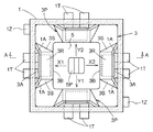
図2は、図1に示すスライド操作式スイッチの横断平面図である。図3は、図1に示すスライド操作式スイッチの縦断平面図(図2のA−A断面図)である。共に非操作状態の中立位置での平面図である。また、理解を容易にするために、ケース1に設けた係合突起1D、1Eや、カバー6は図示を省略している。図2及び図3に示すように、付勢部材3はケース1の壁に接するように収納される。スライダー5は付勢部材3の突出部3Pの背壁部3Bに四方から支持されて中立位置に付勢される。この中立位置において、突出部3Pの天井部3Rの開口部側に備えられた第一導電体3Aは、第一電極対1Aと離間している。また、ケース1の底部1Fの窪みに設けられた第二電極対1Cの上には金属ドーム2が備えられ、図示上方向への付勢力によって付勢部材3の床部3Fの中央を支持している。同心円状の第二電極対1Cの外側の電極は第二導電体としての金属ドーム2と接触しているが、内側の電極は金属ドーム2と離間している。従って、図2及び図3に示した状態では、スライド操作式スイッチは何れの接点も非作動状態である。
FIG. 2 is a cross-sectional plan view of the slide operation type switch shown in FIG. 3 is a vertical plan view (a cross-sectional view taken along line AA in FIG. 2) of the slide operation type switch shown in FIG. Both are plan views at a neutral position in a non-operating state. Further, in order to facilitate understanding, the
図4は、図1に示すスライド操作式スイッチのスライダー5(キートップ7)を付勢部材3の付勢力に抗して矢印X1方向へスライド操作した状態の横断平面図である。図5はその縦断平面図(図4のB−B断面図)である。上述したように、付勢部材3は弾性力に優れた材料により構成されているため、スライダー5により背壁部3Bを押されると、突出部3Pが弾性変形する。本例の構造では、側壁部3Sがそれぞれ側方に広がるように座屈し、これに連動して背壁部3Bもスライダー5の移動方向へ倒れ、これら壁部に支持される天井部3Rも床部3Fの方向へ(図5の矢印D方向へ)倒れ込む。天井部3Rが倒れ込む方向は開口しているので床部3Fは存在せず、天井部3Rの開口部側に設けた第一導電体3Aがケース1の底部1Fに備えた第一電極対1Aに接触する。上述したように第一導電体3Aは第一電極対1Aの2つの電極間よりも長く構成されているので、第一電極対1Aの2つの電極が導通する。尚、この突出部3Pが弾性変形する際には弾性変形の反作用が操作者に伝達され、クリック感を与える。従って、付勢部材3の材料や厚みなどを適宜変更することで、所望のクリック感を得るようにすることができる。
4 is a cross-sectional plan view showing a state in which the slider 5 (key top 7) of the slide operation type switch shown in FIG. 1 is slid in the direction of the arrow X1 against the urging force of the urging
また、特許文献2に記載されているように積極的に複数の第一電極対1Aを同時に導通状態にすることもできる。例えば矢印X1と矢印Y2との中間の方向、方形の床部3Fの角方向にスライダー5をスライド操作すると2ケ所の突出部3Pを同時に弾性変形させることができる。特許文献1に記載されているような揺動操作を伴うスイッチの場合には、各辺へ直交する方向への操作であるか、斜めへの操作であるかが判りにくいため、同時に複数の第一電極対1Aが導通することを抑制している。しかし、本実施形態のようにスライド操作により各辺に直交する方向への操作であるか、斜めへの操作であるかが明確な場合には積極的に斜め方向への操作を活用することができる。斜め方向(角方向)へのスライド操作も加えると4つの第一電極対1Aを用いて、8つの状態を検出することができる。図10は、本発明に係るスライド操作式スイッチの端子接続の一例を示す配線図である。図に示すように、4つの第一電極対1Aと第一導電体3Aとによって、4つの導通状態を検出できる。これに加えて、4つのうちの隣合う2つが同時に導通した状態の4つを検出できるので、合計8つの導通状態を検出することができる。
In addition, as described in
図6は、図1に示すスライド操作式スイッチのスライダー5を矢印Z方向へ押し込み操作した状態の縦断平面図である。スライダー5の押し込み操作に伴い、シート4、付勢部材3、金属ドーム2が弾性変形する。上述したように金属ドーム2の周辺部は、同心円状の第二電極対1Cの外側の電極との間で常閉接点を構成している。金属ドーム2の中心部は同心円状の第二電極対1Cの内側の電極との間で常開接点を構成しているが、この弾性変形により内側の電極に接触する。このようにして、第二電極対1Cの2つの電極が導通する。このとき付勢部材3の突出部3Pにはスライド操作が加えられないので、各突出部3Pに備えられた第一導電体3Aは第一電極対1Aを導通させない。つまり、スライド操作と押し込み操作とが明確に区別可能であるので、第一電極対1A及び第二電極対1Cの導通を明確に切り分けることができる。
FIG. 6 is a longitudinal plan view showing a state in which the
また、上述したように本例の構成では、特許文献2に記載したようにスライダー5の押し込み操作力を伝達するための中間作動部材は不要である。また、第一電極対1Aと、第二電極対1Cとをほぼ同一平面上(底部1F)に備えており、従来のスイッチと比較して薄型に構成できている。つまり、部品点数が少なく、薄型に構成可能なスライド操作式スイッチを提供することができる。
Further, as described above, in the configuration of this example, as described in
以上、本発明を好適且つ技術思想の理解が容易な実施形態を用いて説明したが、勿論上記実施形態に限定されることはない。下記に他の実施形態について簡単に説明を加える。 As described above, the present invention has been described by using the preferred embodiment with easy understanding of the technical idea, but it is needless to say that the present invention is not limited to the above embodiment. Other embodiments will be briefly described below.
〔第一別実施形態〕
図7は、本発明の第一別実施形態に係るスライド操作式スイッチの分解斜視図である。図に示すように、ケース11、第二導電体としての金属ドーム12、付勢部材13、シート14、スライド部材としてのスライダー15、カバー16、キートップ17を順次重ね合わせることによりスライド操作式スイッチを構成する。本実施形態では、付勢部材13に2つの突出部13Pを有しており、スライダー15はこの2つの突出部13Pに挟まれて中立位置に付勢される。スライダー15は、突出部13Pの付勢力に抗して図示矢印X1方向及びX2方向にスライド移動する。カバー16が有する窓部16Wは、スライダー15の係合突起15Pの矢印X1及びX2の方向へ移動を妨げず、矢印X1、X2、Z方向に直行する方向(例えば図1に示す矢印Y1及びY2方向)への移動を規制するように長方形状の形状を有している。
[First embodiment]
FIG. 7 is an exploded perspective view of the slide operation type switch according to the first embodiment of the present invention. As shown in the figure, a slide operation type switch is formed by sequentially stacking a
さらに、カバー16が有する窓部16Wを、矢印X1方向あるいはX2方向の何れか一方の側への移動を規制するように縮めることもできる。つまり、係合突起15Pが中立位置において、窓部16Wの短辺の何れか一方がほぼ接触し、窓部16Wの一方の短辺と、付勢部材13の突出部13Pとによってスライダー15を中立位置に付勢してもよい。このようにすると、スライダー15は矢印X1あるいはX2方向の何れか一方へのスライド移動と、矢印Z方向への押し込み移動を行うものとなる。この場合、スライド操作式スイッチは以下のような構成となる。
Furthermore, the
つまり、ケース11は、底部に1対の第一電極対11Aと、1対の第二電極対11Cとを備えて構成する。付勢部材13を、平坦な床部より立ち上がりスライダー15を中立位置に付勢する背壁部と、この背壁部とは反対側に備えられた第一導電体13Aとを有する突出部13Pを備えて構成する。また、付勢部材13の突出部13Pを有する面とは反対側の面に第二導電体としての金属ドーム12を備える。ケース11と付勢部材13とを、第一電極対11Aと第一導電体13Aとが対向するように且つ第二電極対11Cと金属ドーム12とが対向するように設置する。スライダー15が付勢力に抗して突出部13Pの方向へ操作された場合は、突出部13Pが弾性変形して第一導電体13Aが対向する第一電極対11Aを導通状態とする。スライダー15が中立位置において付勢部材13材の床部方向に押圧された場合は、床部が弾性変形して第二導電体としての金属ドーム12が第二電極対11Cを導通状態とする。
That is, the
〔第二別実施形態〕
本発明は、スライド操作と押し込み操作との2つの操作を伴うスイッチに限らず、押し込み操作を伴わないスライド操作式スイッチにも、もちろん適用することができる。図8は、本発明の第二別実施形態に係るスライド操作式スイッチの分解斜視図である。図に示すように、ケース21、付勢部材23、シート24、スライド部材としてのスライダー25、カバー26、キートップ27を順次重ね合わせることによりスライド操作式スイッチを構成する。ケース21は、底部に少なくとも1対の電極対21Aを備えて構成する。付勢部材23は、平坦な床部より立ち上がりスライダー25を中立位置に付勢する背壁部と、この背壁部とは反対側に備えられた導電体23Aとを有する突出部23Pを備えて構成する。図8に示した例では、電極対21Aを方形状のケース21の底部の四方の外周側にそれぞれ備え、突出部23Pを方形状の付勢部材23の四方の外周にそれぞれ備えて構成している。そして、ケース21と付勢部材23とを電極対21Aと導電体23Aとが対向するように設置する。付勢部材23の突出部23Pの付勢力に抗してスライダー25が、何れか一つ又は二つの突出部23Pの方向へ操作された場合は、図2〜5に示した場合と同様に、これ又はこれらの突出部23Pが弾性変形する。そして、弾性変形した突出部23Pが有する導電体23Aが対向する電極対21Aを導通状態とする。
[Second Embodiment]
The present invention is not limited to a switch that involves two operations, a slide operation and a push-in operation, but can of course be applied to a slide-operated switch that does not involve a push-in operation. FIG. 8 is an exploded perspective view of a slide operation type switch according to a second embodiment of the present invention. As shown in the drawing, a slide operation type switch is configured by sequentially superposing a
〔第三別実施形態〕
図9は、本発明の第三別実施形態に係るスライド操作式スイッチの分解斜視図である。図に示すように、ケース31、付勢部材33、シート34、スライド部材としてのスライダー35、カバー36、キートップ37を順次重ね合わせることによりスライド操作式スイッチを構成する。本実施形態では、付勢部材33に2つの突出部33Pを有しており、スライダー35はこの2つの突出部33Pに挟まれて中立位置に付勢される。スライダー35は、突出部33Pの付勢力に抗して図示矢印X1方向及びX2方向にスライド移動する。カバー36が有する窓部36Wは、スライダー35の係合突起35Pの矢印X1及びX2の方向へ移動を妨げず、矢印X1、X2、Z方向に直行する方向(例えば図1に示す矢印Y1及びY2方向)への移動を規制するように長方形状の形状を有している。
[Third Embodiment]
FIG. 9 is an exploded perspective view of a slide operation type switch according to another embodiment of the present invention. As shown in the figure, a slide operation type switch is configured by sequentially superposing a
さらに、カバー36が有する窓部36Wを、矢印X1方向あるいはX2方向の何れか一方の側への移動を規制するように縮めることもできる。つまり、係合突起35Pが中立位置において、窓部36Wの短辺の何れか一方がほぼ接触し、窓部36Wの一方の短辺と、付勢部材33の突出部33Pとによってスライダー35を中立位置に付勢してもよい。このようにすると、スライダー35は矢印X1あるいはX2方向の何れか一方へのスライド移動のみを行うものとなる。この場合、スライド操作式スイッチは以下のような構成となる。つまり、ケース31は底部に1対の電極対31Aを備えて構成する。付勢部材33を、平坦な床部より立ち上がりスライダー15を中立位置に付勢する背壁部と、この背壁部とは反対側に備えられた導電体33Aとを有する突出部33Pを備えて構成する。ケース31と付勢部材33とを電極対31Aと導電体33Aとが対向するように設置し、スライダー15が付勢力に抗して突出部13Pの方向へ操作された場合は、突出部13Pが弾性変形して第一導電体13Aが対向する第一電極対11Aを導通状態とする。
Furthermore, the
〔第四別実施形態〕
また、端子接続についても、図1〜図10に示した形態に限定されることはない。図10には、図1に示した構成のスライド操作式スイッチに対応した端子接続を示している。つまり、第一電極対1A及び第二電極対1Cのそれぞれの電極対を構成する2つの電極の導通を独立して検出する端子接続を示している。図10に示したように4つの第一電極対1Aと、1つの第二電極対1Cとを有する場合、5つの閉回路を独立して構成できるような端子接続である。
[Fourth embodiment]
Also, the terminal connection is not limited to the form shown in FIGS. FIG. 10 shows terminal connections corresponding to the slide operation type switch having the configuration shown in FIG. That is, the terminal connection which detects independently conduction | electrical_connection of the two electrodes which comprise each electrode pair of 1A of 1st electrode pairs and 1C of 2nd electrodes is shown. As shown in FIG. 10, when there are four first electrode pairs 1A and one
図11には、4つの第一電極対1Aと、1つの第二電極対1Cとを有する場合であっても、それぞれの電極対の一方の電極を全てに共通な端子(コモン端子CMN)とする例を示している。この場合、スライド操作式スイッチの外部へ出る端子としての第一端子対1Tは、1つの端子で構成される第一端子41Tとなる。図11に示した例では、第二端子対1Zは、図10と同様に2つの端子で構成されるが、一方の端子はコモン端子CMNとなる。
In FIG. 11, even if there are four first electrode pairs 1A and one
このようにコモン端子CMNを設けると、例えば次のような利用をする場合に有益である。図4及び図5を用いて説明したように、スライダー5は各辺に垂直な方向へのスライド操作に留まらず、各角の方向へのスライド操作も可能である。そして、角方向へスライド操作した場合には、隣合う2つの第一電極対1Aが導通する。2つの第一電極対1Aが同時に導通したことを確認するためには、それぞれの第一電極対1Aの導通を確認する必要がある。しかし、図11のようにコモン端子を設けると、一つの第一端子41Tとこれに隣合う第一端子41Tとの間の導通を検出すれば、2つの第一電極対1Aが同時に導通したことを確認することができる。従って、このスライド操作式スイッチを利用した周辺回路を簡潔にすることができる。もちろん、端子接続は、図10及び図11に示したものに限ることなく、適宜種々の変更が可能である。
Providing the common terminal CMN in this way is beneficial for the following usage, for example. As described with reference to FIGS. 4 and 5, the
〔第五別実施形態〕
本発明の特徴のひとつとして、図1〜図7に示したように第一電極対1Aと、第二電極対1Cとをほぼ同一平面上(底部1F)に備えており、従来のスイッチと比較して薄型に構成できている点が挙げられる。上述したように第二電極対1Cに対応する第二導電体としての金属ドーム2を所定位置に留めるために、ケース1の底部1Fの中心部に窪みを設け、この窪みに第二電極対1Cを形成している。そして、この窪みに金属ドーム2が留まるように構成している。しかし、この形態に限定することなく、例えば図12のように構成してもよい。即ち、ケース1の底部1Fの中央部には窪みを設けず、第一電極対1Aと第二電極対1Cとを同一平面上に構成する。そして、金属ドーム2を所定の位置に留めるための突起1Pを設けてもよい。
[Fifth embodiment]
As one of the features of the present invention, as shown in FIGS. 1 to 7, the
以上、本発明によって、部品点数が少なく、薄型に構成可能なスライド操作式スイッチを提供することができる。 As described above, according to the present invention, it is possible to provide a slide operation type switch that has a small number of parts and can be configured to be thin.
1 ケース
1A 第一電極対(電極対)
1C 第二電極対
1F 底部
1P 突起
2 金属ドーム(第二導電体)
3 付勢部材
3A 第一導電体(導電体)
3B 背壁部
3F 床部
3P 突起部
3R 天井部
3S 側壁部
5 スライダー(スライド部材)
1
1C
3 Biasing
3R ceiling
Claims (6)
前記ケースを、底部に少なくとも1対の電極対を備えて構成し、
前記付勢部材を、前記スライド移動方向に沿う平坦な床部から前記スライド部材に対して前記スライド移動方向で対向する横側に立ち上がり当該スライド部材を前記中立位置に付勢する背壁部と、この背壁部の前記スライド部材の存在側とは反対側に備えられた導電体と、前記背壁部の両端の側壁部と、前記背壁部及び前記側壁部に支持される天井部とを有する突出部を備えて構成し、
前記付勢部材は、前記スライド移動方向に直交する方向から前記底部に重ねてあり、
前記スライド部材が付勢力に抗して前記突出部の方向へ操作された場合には、この突出部が弾性変形して前記背壁部が前記ケースの底部の側に倒れることにより、前記導電体を介して前記電極対の各電極同士が導通するスライド操作式スイッチ。 A slide member housed slidably with respect to the case, a biasing member that biases the slide member to a neutral position, and an electric power when the slide member is operated against the biasing force of the biasing member A slide-operated switch that produces an electrical conduction state,
The case comprises at least one pair of electrodes on the bottom;
A back wall portion for raising the biasing member from a flat floor portion along the sliding movement direction to a lateral side facing the sliding member in the sliding movement direction and biasing the sliding member to the neutral position; A conductor provided on the side of the back wall opposite to the side where the slide member is present, side walls at both ends of the back wall, and a ceiling supported by the back wall and the side wall. Comprising a protrusion having ,
The biasing member is stacked on the bottom from a direction orthogonal to the sliding movement direction,
When the slide member is operated in the direction of the projecting portion against an urging force, the projecting portion is elastically deformed and the back wall portion falls to the bottom side of the case, whereby the conductor A slide-operated switch in which the electrodes of the electrode pair are electrically connected to each other via a pin.
前記付勢力に抗して前記スライド部材が何れか一つ又は二つの前記突出部の方向へ操作された場合は、当該一つ又は二つの突出部が有する前記導電体を介して前記電極対の各電極同士が導通する請求項1に記載のスライド操作式スイッチ。 The electrode pair and the protrusion are respectively provided on the four outer peripheral sides of the bottom portion of the rectangular case,
When the slide member is operated in the direction of one or two of the protrusions against the biasing force, the electrode pair is connected via the conductors of the one or two protrusions. The slide operation type switch according to claim 1, wherein the electrodes are electrically connected to each other.
前記ケースを、底部に少なくとも1対の第一電極対と、1対の第二電極対とを備えて構成し、
前記付勢部材を、前記スライド移動方向に沿う平坦な床部から前記スライド部材に対して前記スライド移動方向で対向する横側に立ち上がり前記スライド部材を前記中立位置に付勢する背壁部と、この背壁部の前記スライド部材の存在側とは反対側に備えられた第一導電体と、前記背壁部の両端の側壁部と、前記背壁部及び前記側壁部に支持される天井部とを有する突出部を備えて構成すると共に、前記床部の前記スライド部材の存在側とは反対側に第二導電体を備え、
前記付勢部材は、前記スライド移動方向に直交する方向から前記底部に重ねてあり、
前記スライド部材が付勢力に抗して前記突出部の方向へ操作された場合には、この突出部が弾性変形して前記背壁部が前記ケースの底部の側に倒れることにより、前記第一導電体を介して前記第一電極対の各電極同士が導通し、前記スライド部材が前記中立位置において前記床部の方向に押圧された場合には、前記第二導電体を介して前記第二電極対の各電極同士が導通するスライド操作式スイッチ。 A slide member housed slidably with respect to the case, a biasing member that biases the slide member to a neutral position, and an electric power when the slide member is operated against the biasing force of the biasing member A slide-operated switch that produces an electrical conduction state,
The case is configured to include at least one first electrode pair and one second electrode pair at the bottom,
A back wall portion that raises the biasing member from a flat floor portion along the sliding movement direction to a lateral side facing the sliding member in the sliding movement direction, and biases the sliding member to the neutral position; A first conductor provided on the opposite side of the back wall portion from the side where the slide member is present, side wall portions at both ends of the back wall portion, and a ceiling portion supported by the back wall portion and the side wall portion. And a second conductor on the opposite side of the floor from the slide member ,
The biasing member is stacked on the bottom from a direction orthogonal to the sliding movement direction,
When the slide member is operated in the direction of the protrusion against the urging force, the protrusion is elastically deformed, and the back wall portion falls toward the bottom of the case, so that the first When the electrodes of the first electrode pair are electrically connected to each other through the conductor, and the slide member is pressed toward the floor portion at the neutral position, the second electrode is interposed through the second conductor. A slide-operated switch that connects each electrode of an electrode pair.
前記付勢力に抗して前記スライド部材が何れか一つ又は二つの前記突出部の方向へ操作された場合は、当該一つ又は二つの突出部が有する前記第一導電体を介して前記第一電極対の各電極同士が導通する請求項3に記載のスライド操作式スイッチ。 The first electrode pair and the protrusion are respectively provided on the outer peripheral sides of the four sides of the bottom of the rectangular case,
When the slide member is operated in the direction of any one or two of the protrusions against the urging force, the first conductor is included in the first or two protrusions. The slide operation type switch according to claim 3, wherein each electrode of one electrode pair conducts.
The slide operation type switch according to claim 5, further comprising a plurality of protrusions for restricting the metal dome on an outer periphery of the second electrode pair.
Priority Applications (6)
| Application Number | Priority Date | Filing Date | Title |
|---|---|---|---|
| JP2005133129A JP4446925B2 (en) | 2005-04-28 | 2005-04-28 | Slide operation switch |
| TW095105819A TW200644018A (en) | 2005-04-28 | 2006-02-21 | Slide operating type switch |
| KR1020060020696A KR100800242B1 (en) | 2005-04-28 | 2006-03-04 | Slide operating type switch |
| EP06008640A EP1717835B1 (en) | 2005-04-28 | 2006-04-26 | Slide switch |
| CN200610077153A CN100576400C (en) | 2005-04-28 | 2006-04-27 | Slide operation type switch |
| US11/412,537 US7282656B2 (en) | 2005-04-28 | 2006-04-27 | Slide switch |
Applications Claiming Priority (1)
| Application Number | Priority Date | Filing Date | Title |
|---|---|---|---|
| JP2005133129A JP4446925B2 (en) | 2005-04-28 | 2005-04-28 | Slide operation switch |
Publications (2)
| Publication Number | Publication Date |
|---|---|
| JP2006310179A JP2006310179A (en) | 2006-11-09 |
| JP4446925B2 true JP4446925B2 (en) | 2010-04-07 |
Family
ID=36845405
Family Applications (1)
| Application Number | Title | Priority Date | Filing Date |
|---|---|---|---|
| JP2005133129A Expired - Fee Related JP4446925B2 (en) | 2005-04-28 | 2005-04-28 | Slide operation switch |
Country Status (6)
| Country | Link |
|---|---|
| US (1) | US7282656B2 (en) |
| EP (1) | EP1717835B1 (en) |
| JP (1) | JP4446925B2 (en) |
| KR (1) | KR100800242B1 (en) |
| CN (1) | CN100576400C (en) |
| TW (1) | TW200644018A (en) |
Families Citing this family (24)
| Publication number | Priority date | Publication date | Assignee | Title |
|---|---|---|---|---|
| DE202005001495U1 (en) * | 2005-01-31 | 2005-06-09 | Trw Automotive Electronics & Components Gmbh & Co. Kg | 2-pole changeover switch |
| JP4721874B2 (en) * | 2005-11-02 | 2011-07-13 | ホシデン株式会社 | Slide operation switch |
| JP4675282B2 (en) * | 2006-06-14 | 2011-04-20 | 帝国通信工業株式会社 | Multi-directional sliding electronic parts |
| US20080029374A1 (en) * | 2006-07-24 | 2008-02-07 | Motorola, Inc. | Switch and method for operation thereof |
| KR100810314B1 (en) * | 2006-10-11 | 2008-03-04 | 삼성전자주식회사 | Key input apparatus for portable communication device |
| JP4680170B2 (en) * | 2006-11-29 | 2011-05-11 | トヨタ紡織株式会社 | Electric operating device for vehicle seat |
| JP4917416B2 (en) * | 2006-11-29 | 2012-04-18 | トヨタ紡織株式会社 | Electric operating device for vehicle seat |
| JP5087958B2 (en) * | 2007-03-07 | 2012-12-05 | 東レ株式会社 | Molded product comprising liquid crystalline resin composition |
| JP4857183B2 (en) * | 2007-05-10 | 2012-01-18 | アルプス電気株式会社 | Combined operation type switch device |
| CN101312102B (en) * | 2007-05-25 | 2012-08-22 | 深圳富泰宏精密工业有限公司 | Keyboard module and portable electronic device provided with the keyboard module |
| FR2919425B1 (en) * | 2007-07-24 | 2009-10-02 | Itt Ind Soc Par Actions Simpli | ELECTRICAL SWITCH WITH MULTIPLE SWITCHES. |
| JP5006293B2 (en) * | 2007-09-21 | 2012-08-22 | アルプス電気株式会社 | Slide operation mechanism and slide operation type switch device provided with the mechanism |
| WO2009062360A1 (en) * | 2007-11-16 | 2009-05-22 | Hewlett-Packard Technology (Shanghai) Co., Ltd. | Structures for multi-directional operation buttons |
| JP2009224212A (en) * | 2008-03-17 | 2009-10-01 | Hosiden Corp | Slide operation type switch |
| US8970496B2 (en) * | 2008-04-15 | 2015-03-03 | Razer (Asia-Pacific) Pte. Ltd. | Ergonomic slider-based selector |
| KR20100098121A (en) * | 2009-02-27 | 2010-09-06 | 삼성전자주식회사 | Button assembly and digital camera having the same |
| US9234979B2 (en) | 2009-12-08 | 2016-01-12 | Magna Closures Inc. | Wide activation angle pinch sensor section |
| US8493081B2 (en) | 2009-12-08 | 2013-07-23 | Magna Closures Inc. | Wide activation angle pinch sensor section and sensor hook-on attachment principle |
| US20110183759A1 (en) * | 2010-01-27 | 2011-07-28 | Chu-Keng Lin | Joystick Controller |
| JP5551509B2 (en) | 2010-05-13 | 2014-07-16 | デルタ工業株式会社 | Slide switch |
| JP5838946B2 (en) * | 2012-10-15 | 2016-01-06 | 住友電装株式会社 | Combined operation device |
| KR101501141B1 (en) * | 2013-09-17 | 2015-03-12 | (주)코텍 | Control knob with image equipment |
| KR102032991B1 (en) * | 2018-04-05 | 2019-10-16 | 동서콘트롤(주) | Vehicle lever |
| KR20210078782A (en) * | 2019-12-19 | 2021-06-29 | 현대자동차주식회사 | Multi-directional switch |
Family Cites Families (16)
| Publication number | Priority date | Publication date | Assignee | Title |
|---|---|---|---|---|
| JPH09129090A (en) * | 1995-11-06 | 1997-05-16 | Alps Electric Co Ltd | Switch device |
| JPH1021795A (en) | 1996-07-05 | 1998-01-23 | Mitsumi Electric Co Ltd | Multi-slide switch |
| JP3470022B2 (en) | 1997-09-30 | 2003-11-25 | ホシデン株式会社 | Multi-contact input device |
| JP2001135196A (en) * | 1999-11-02 | 2001-05-18 | Hosiden Corp | Sliding switch |
| DE10000598A1 (en) * | 2000-01-10 | 2001-07-12 | Eaton Corp | Electrical switch |
| JP3732380B2 (en) * | 2000-03-09 | 2006-01-05 | ホシデン株式会社 | Pointing device |
| JP3652234B2 (en) | 2000-10-31 | 2005-05-25 | ホシデン株式会社 | Slide operation switch |
| TW516060B (en) * | 2000-10-31 | 2003-01-01 | Hosiden Corp | Slide switch |
| JP3923253B2 (en) * | 2000-12-28 | 2007-05-30 | ホシデン株式会社 | Pointing device |
| JP2003059374A (en) | 2001-06-04 | 2003-02-28 | Mic Electron Co | Slide switch |
| US6689967B2 (en) * | 2002-03-11 | 2004-02-10 | Mitsuku Denshi Kogyo K.K. | Slide switch |
| JP4147839B2 (en) * | 2002-06-26 | 2008-09-10 | ポリマテック株式会社 | Sliding multi-directional input key |
| FR2844094B1 (en) * | 2002-08-28 | 2005-11-18 | Itt Mfg Enterprises Inc | MULTIPLE SWITCHING DEVICE |
| US6765165B1 (en) * | 2003-12-20 | 2004-07-20 | Lear Corporation | Electric switch |
| US6831238B1 (en) * | 2004-01-16 | 2004-12-14 | Nokia Corporation | Finger-controllable multi-directional switch |
| JP4268537B2 (en) * | 2004-02-20 | 2009-05-27 | アルプス電気株式会社 | Multi-directional input device |
-
2005
- 2005-04-28 JP JP2005133129A patent/JP4446925B2/en not_active Expired - Fee Related
-
2006
- 2006-02-21 TW TW095105819A patent/TW200644018A/en not_active IP Right Cessation
- 2006-03-04 KR KR1020060020696A patent/KR100800242B1/en not_active IP Right Cessation
- 2006-04-26 EP EP06008640A patent/EP1717835B1/en not_active Expired - Fee Related
- 2006-04-27 CN CN200610077153A patent/CN100576400C/en not_active Expired - Fee Related
- 2006-04-27 US US11/412,537 patent/US7282656B2/en not_active Expired - Fee Related
Also Published As
| Publication number | Publication date |
|---|---|
| US20060260925A1 (en) | 2006-11-23 |
| CN100576400C (en) | 2009-12-30 |
| TW200644018A (en) | 2006-12-16 |
| TWI311330B (en) | 2009-06-21 |
| CN1855337A (en) | 2006-11-01 |
| EP1717835B1 (en) | 2011-12-14 |
| JP2006310179A (en) | 2006-11-09 |
| EP1717835A2 (en) | 2006-11-02 |
| KR100800242B1 (en) | 2008-02-01 |
| KR20060113382A (en) | 2006-11-02 |
| US7282656B2 (en) | 2007-10-16 |
| EP1717835A3 (en) | 2007-12-19 |
Similar Documents
| Publication | Publication Date | Title |
|---|---|---|
| JP4446925B2 (en) | Slide operation switch | |
| JP4487821B2 (en) | Composite operation type electronic parts | |
| US8022326B2 (en) | Push switch | |
| US20100140065A1 (en) | Multi-step pressurized switch | |
| JP2009266700A (en) | Push-operation type electronic component and push-switch | |
| JP2001266700A (en) | Push switch | |
| CN109690716B (en) | Push switch | |
| JP3178218U (en) | Click spring and push switch using the click spring | |
| US20110083946A1 (en) | Slide Switch | |
| JP2001210178A (en) | Electric switch | |
| US10026568B2 (en) | Electronic device with switch mechanism mounted to substrate | |
| JP5376026B2 (en) | Push switch | |
| JP5428890B2 (en) | Push-on switch | |
| JP4278529B2 (en) | Multi-directional input device | |
| JP2022043622A (en) | Push switch | |
| TW543056B (en) | Multi-direction input device | |
| JP4032381B2 (en) | Pushing connector | |
| KR101100403B1 (en) | Multi-step operation electrical switch | |
| JP2010080330A (en) | Multidirectional input device | |
| KR200297764Y1 (en) | Tack-switch | |
| JP2003151404A (en) | Multidirectional input device | |
| JP2001222926A (en) | Operation button holding structure and electronic equipment having the same | |
| KR101418047B1 (en) | Tact switch for electronic component | |
| KR100766044B1 (en) | A structure of switch | |
| JPH05290670A (en) | Push-button switch |
Legal Events
| Date | Code | Title | Description |
|---|---|---|---|
| A621 | Written request for application examination |
Free format text: JAPANESE INTERMEDIATE CODE: A621 Effective date: 20070319 |
|
| A977 | Report on retrieval |
Free format text: JAPANESE INTERMEDIATE CODE: A971007 Effective date: 20090812 |
|
| A131 | Notification of reasons for refusal |
Free format text: JAPANESE INTERMEDIATE CODE: A131 Effective date: 20090910 |
|
| A521 | Written amendment |
Free format text: JAPANESE INTERMEDIATE CODE: A523 Effective date: 20091105 |
|
| TRDD | Decision of grant or rejection written | ||
| A01 | Written decision to grant a patent or to grant a registration (utility model) |
Free format text: JAPANESE INTERMEDIATE CODE: A01 Effective date: 20100107 |
|
| A01 | Written decision to grant a patent or to grant a registration (utility model) |
Free format text: JAPANESE INTERMEDIATE CODE: A01 |
|
| A61 | First payment of annual fees (during grant procedure) |
Free format text: JAPANESE INTERMEDIATE CODE: A61 Effective date: 20100119 |
|
| FPAY | Renewal fee payment (event date is renewal date of database) |
Free format text: PAYMENT UNTIL: 20130129 Year of fee payment: 3 |
|
| R150 | Certificate of patent or registration of utility model |
Free format text: JAPANESE INTERMEDIATE CODE: R150 |
|
| FPAY | Renewal fee payment (event date is renewal date of database) |
Free format text: PAYMENT UNTIL: 20130129 Year of fee payment: 3 |
|
| FPAY | Renewal fee payment (event date is renewal date of database) |
Free format text: PAYMENT UNTIL: 20140129 Year of fee payment: 4 |
|
| LAPS | Cancellation because of no payment of annual fees |