CN100428373C - Mounting structure of resistors with lead wires - Google Patents
Mounting structure of resistors with lead wires Download PDFInfo
- Publication number
- CN100428373C CN100428373C CNB2004100584979A CN200410058497A CN100428373C CN 100428373 C CN100428373 C CN 100428373C CN B2004100584979 A CNB2004100584979 A CN B2004100584979A CN 200410058497 A CN200410058497 A CN 200410058497A CN 100428373 C CN100428373 C CN 100428373C
- Authority
- CN
- China
- Prior art keywords
- resistor
- bracket
- circuit board
- hole
- wire
- Prior art date
- Legal status (The legal status is an assumption and is not a legal conclusion. Google has not performed a legal analysis and makes no representation as to the accuracy of the status listed.)
- Expired - Lifetime
Links
- 239000000919 ceramic Substances 0.000 claims abstract description 9
- 238000009434 installation Methods 0.000 claims description 17
- 230000017525 heat dissipation Effects 0.000 abstract description 9
- WABPQHHGFIMREM-UHFFFAOYSA-N lead(0) Chemical compound [Pb] WABPQHHGFIMREM-UHFFFAOYSA-N 0.000 abstract description 3
- 229910000679 solder Inorganic materials 0.000 description 16
- 238000005476 soldering Methods 0.000 description 10
- 238000000034 method Methods 0.000 description 9
- 238000003466 welding Methods 0.000 description 8
- 230000002411 adverse Effects 0.000 description 4
- 230000000694 effects Effects 0.000 description 4
- 239000000463 material Substances 0.000 description 3
- 229920003002 synthetic resin Polymers 0.000 description 2
- 239000000057 synthetic resin Substances 0.000 description 2
- 230000000593 degrading effect Effects 0.000 description 1
- 230000002542 deteriorative effect Effects 0.000 description 1
- 238000010586 diagram Methods 0.000 description 1
Images


Landscapes
- Details Of Resistors (AREA)
- Structures For Mounting Electric Components On Printed Circuit Boards (AREA)
Abstract
本发明提供一种不损坏空间系数和散热性来提高独立强度的带导线的电阻器以及其安装结构。带导线的电阻器(11)是由以竖立姿势保持在线路板(20)上的电阻主体(12)、一对突出于电阻器主体(12)的两端而设置并穿过线路板(20)的导线安装孔(21、22)的导线端子(13、14)、具有让一个导线端子(14)穿过的中央孔(16)并安装在电阻器主体(12)的一端的陶瓷制支架(15)所构成。在支架的上下两面形成与中央孔(16)的两端连通的一对凹部(17、18),在一个凹部(17)内插入电阻器主体(12)的一端。并且,在把该带导线的电阻器(11)安装到线路板(20)上时,以使另一个凹部(18)与导线安装孔(22)对向的状态把支架(15)搭载到线路板(20)上。
The present invention provides a resistor with leads and a mounting structure thereof, which improve independent strength without impairing space factor and heat dissipation. The resistor (11) with wire is to be kept on the resistance body (12) on the circuit board (20) with upright attitude, a pair of two ends protruding from the resistor body (12) are arranged and pass through the circuit board (20 ), the lead terminals (13, 14) of the lead wire mounting holes (21, 22), a ceramic bracket having a central hole (16) through which a lead lead terminal (14) passes and installed at one end of the resistor body (12) (15) constituted. A pair of recesses (17, 18) communicating with both ends of the central hole (16) are formed on the upper and lower surfaces of the bracket, and one end of the resistor main body (12) is inserted into one recess (17). And, when the resistor (11) with lead is installed on the circuit board (20), the bracket (15) is mounted on the circuit so that the other recess (18) is opposite to the lead mounting hole (22). plate (20).
Description
技术领域 technical field
本发明涉及以竖立姿势安装在线路板上的带导线的电阻器及其安装结构。The invention relates to a resistor with wires installed on a circuit board in an upright position and its installation structure.
背景技术 Background technique
导线端子突出于电阻器主体的两端而设置的带导线的电阻器虽然也有横向安装在线路板上的,为了提高安装密度和散热效果,多为以竖立姿势安装在线路板上。然而,由于仅把这种竖置型(径向式)带导线的电阻器安装在线路板上时其独立的强度较弱,在组装过程中,在外力作用了的时候易于倾斜,会有比如导线端子接触到其他部件而引起短路的事故。Although the resistors with leads protruding from both ends of the resistor body are installed horizontally on the circuit board, in order to improve the installation density and heat dissipation effect, they are mostly installed on the circuit board in an upright position. However, since the independent strength of this vertical (radial type) resistor with leads is only installed on the circuit board, its independent strength is weak, and it is easy to tilt when an external force acts during the assembly process. An accident in which the terminal contacts other parts and causes a short circuit.
对此,以前为了提高竖置型带导线的电阻器的独立强度,提出了以在该电阻器上附属设置专用支架的状态来安装到的线路板上的技术方案(例如,参照专利文献1)。In contrast, conventionally, in order to improve the independent strength of a vertical type leaded resistor, it has been proposed to mount the resistor on a circuit board with a dedicated bracket attached thereto (for example, refer to Patent Document 1).
图4是用于说明该原有技术的图,该图中所示的带导线的电阻器1是由电阻器主体2和一对导线端子3、4以及支架5所构成。由线材组成的导线端子3、4突出于略圆柱状的电阻器主体2的两端而设置,一个导线端子3被弯曲成U字形。由具有耐热性的合成树脂材料所构成的支架5备有形成有通孔6的竖立部5a和形成有狭槽7的底板部5b,一个导线端子3穿过通孔6,另一个导线端子4穿过狭槽7。在实际安装该带导线的电阻器1的时候,将一对导线端子3、4的各前端部穿过分别与无图示的线路板对应的导线安装孔,将支架5搭载到该线路板上后,将导线端子3、4的各前端部焊接到所对应的焊环(ランド)上。这样,所安装的带导线的电阻器1由于成为以支架5承受作用于线路板上的电阻器主体2的外力的结构,所以能够大幅提高独立强度。FIG. 4 is a diagram for explaining this prior art. A resistor 1 with leads shown in the figure is composed of a
【专利文献1】实开平1-115291号公报(第4页,第2图)[Patent Document 1] Utility Application Publication No. 1-115291 (
图4所示那样的原有的带导线的电阻器1虽然对提高独立的强度是有效的,但是由于不得不附属设置比较大的支架5,从而存在空间系数(スペ一スフアクタ)变差的问题。另外,由合成树脂材料构成的支架5散热性不好,由于积蓄电阻器主体2所产生的热量而导致相当高的温度,从而会有对周围的焊锡等产生不良影响的担心。Although the conventional resistor 1 with lead wires as shown in FIG. 4 is effective for improving independent strength, it has the problem of degrading the space factor because a relatively large bracket 5 has to be attached. . In addition, the holder 5 made of synthetic resin material has poor heat dissipation, and the heat generated by the resistor
发明内容 Contents of the invention
本发明是鉴于这种原有技术的实际情况而产生的,其第1目的是提供一种不损害空间系数和散热性而提高独立的强度的带导线的电阻器。另外,本发明的第2目的是提供该带导线的电阻器的安装结构。The present invention has been made in view of the actual situation of the prior art, and its first object is to provide a resistor with leads having improved independent strength without impairing space factor and heat dissipation. Moreover, the 2nd object of this invention is to provide the mounting structure of this resistor with lead wire.
为了达成上述第一目的,本发明的带导线的电阻器采用了以下结构:备有:以竖立姿势安装在线路板上的电阻器主体、一对突出于该电阻器主体的两端而设置并穿过上述电路板的导线安装孔的导线端子、具有使一个上述导线端子穿过的通孔并安装在上述电阻器主体的一端的耐热性支架,在上述支架上设置与上述通孔的两端连通的一对凹部,在其中一个凹部内插入上述电阻器主体的一端,同时,以使另一个凹部与上述导线安装孔对向的状态把该支架搭载到上述线路板上。In order to achieve the above-mentioned first object, the resistor with leads of the present invention adopts the following structure: it has: a resistor main body installed on a circuit board in an upright posture, a pair of two ends protruding from the resistor main body are provided and A wire terminal passing through the wire mounting hole of the above-mentioned circuit board, a heat-resistant bracket having a through hole through which one of the above-mentioned wire terminals passes and mounted on one end of the above-mentioned resistor main body, and two sides of the above-mentioned through hole are provided on the above-mentioned bracket. One end of the resistor main body is inserted into one of the recesses connected to each other, and the bracket is mounted on the circuit board with the other recess facing the wire mounting hole.
这样所构成的竖置型带导线的电阻器在将一个导线端子被穿过的支架搭载到线路板上后,将两个导线的各前端部焊接在设在线路板的焊环上而成为安装的状态,由于在该状态电阻器主体的一端被插入支架背对电路板侧的凹部内,所以作用在线路板上电阻器主体的外力能够被支架承受,得到了十分大的独立强度。另外,由于支架在线路板侧的凹部与该线路板的导线安装孔对向,而使得在焊接过程中浸入该导线安装孔内的溶化的焊锡浸入该凹部内并附着在一个导线端子的基端部,因而焊接强度得到提高并且独立强度有望能够进一步提高。由于安装在电阻器主体一端的支架也可以是直径小且低矮的材料,所以即使附属设置该支架也不用担心有损空间系数。The vertical type resistor with leads constituted in this way is mounted on the circuit board after the bracket through which one lead terminal is passed, and then the front ends of the two leads are soldered to the solder rings provided on the circuit board to become mounted. In this state, since one end of the resistor main body is inserted into the recess on the side of the bracket facing away from the circuit board, the external force acting on the resistor main body on the circuit board can be borne by the bracket, and a very large independent strength is obtained. In addition, since the recess of the bracket on the side of the circuit board is opposite to the wire installation hole of the circuit board, the melted solder immersed in the wire installation hole during the soldering process is immersed in the recess and adheres to the base end of a wire terminal. Therefore, the welding strength is improved and the independent strength is expected to be further improved. Since the bracket attached to one end of the resistor main body can also be made of a small-diameter and low-profile material, there is no need to worry about deteriorating the space factor even if the bracket is provided additionally.
该结构的带导线的电阻器较好是在穿过上述通孔的一个导线端子上通过压溃加工来形成展宽部,通过将该展宽部压入该通孔内来把支架安装在电阻器主体的一端,这样,安装前能够简单地支架安装在电阻器主体的一端而使得组装性良好,并且,在安装时由于能够把电阻器主体和支架作为一体品来处理而使得作业效率良好。In the resistor with leads of this structure, it is preferable to form a widened part by crushing on one lead terminal passing through the above-mentioned through hole, and mount the bracket on the resistor body by pressing the widened part into the through hole. In this way, the bracket can be simply installed on one end of the resistor body before installation, so that the assemblability is good, and because the resistor body and the bracket can be handled as an integral product during installation, the work efficiency is good.
另外,该结构的带导线的电阻器较好是以陶瓷制成(例如,块滑石)支架,这样,由于支架的散热性提高从而不用担心对周围的焊锡等产生不良影响。In addition, the lead wire resistor of this structure is preferably made of ceramic (for example, steatite) support, so that there is no need to worry about adverse effects on the surrounding solder due to the improved heat dissipation of the support.
另外,该结构的带导线的电阻器较好是上述一对凹部形状相同,这样,由于支架的上下没有区别而组装,从而使得组装更加容易。In addition, it is preferable that the above-mentioned pair of recessed parts have the same shape in the leaded resistor with this structure, so that it can be assembled without distinction between the upper and lower sides of the bracket, which makes the assembly easier.
另外,为了达成上述第2目的,本发明的带导线的电阻器的安装结构采用了以下结构,备有:以竖立姿势安装在线路板上的电阻器主体、一对突出于该电阻器主体的两端而设置的并穿过上述电路板的导线安装孔的导线端子、具有使一个上述导线端子穿过的通孔并介于上述电阻器主体和上述线路板之间而设置的耐热性支架,在上述支架上设置与上述通孔的两端连通的一对凹部,在其中一个凹部内插入上述电阻器主体的一端,同时,以使另一个凹部与上述导线安装孔对向的状态把该支架搭载到上述线路板上。In addition, in order to achieve the above-mentioned second object, the mounting structure of the resistor with leads of the present invention adopts the following structure: a resistor main body mounted on a circuit board in an upright posture; Lead terminals provided at both ends and passing through the lead mounting hole of the above-mentioned circuit board, a heat-resistant bracket provided between the above-mentioned resistor main body and the above-mentioned circuit board having a through hole through which one of the above-mentioned lead terminals passes through A pair of recesses communicating with both ends of the above-mentioned through hole is provided on the above-mentioned bracket, and one end of the above-mentioned resistor body is inserted into one of the recesses, and at the same time, the other recess is placed opposite to the above-mentioned wire installation hole. The bracket is mounted on the above-mentioned circuit board.
在这样的带导线的电阻器的安装结构中,被一个导线端子穿过的支架介于在竖立姿势的电阻器主体和线路板之间而设置,带导线的电阻器通过将两个导线端子各自的前端部焊接在设于线路板上的焊环上而成为安装的状态,由于在该状态,电阻器主体的一端被插入支架背对线路板一侧的凹部内,所以能够以支架承受作用在线路板上的电阻器主体的外力,从而得到十分大的独立强度。另外,由于支架在线路板侧的凹部与该线路板的导线安装孔对向,从而在焊接过程中浸入该导线安装孔的溶化焊锡浸入该凹部内而附着在一个导线端子的基端部,因而焊接强度得到提高而使独立的强度进一步提高。并且,由于介于电阻器主体和线路板之间设置支架也可以是直径小且低矮的部件,从而不会有因该支架而损坏空间系数的担心。In such a mounting structure of a resistor with leads, a bracket through which one lead terminal passes is provided between the resistor main body in an upright position and the circuit board, and the resistor with leads is formed by placing the two lead terminals respectively. The front end of the resistor is welded on the solder ring on the circuit board to become the installed state. In this state, one end of the resistor body is inserted into the recess on the side of the bracket facing away from the circuit board, so the bracket can bear the action on the circuit board. The external force of the resistor body on the circuit board, thus obtaining a very large independent strength. In addition, since the recess of the bracket on the circuit board side faces the wire mounting hole of the circuit board, the melted solder that has penetrated into the wire mounting hole during the soldering process enters the recess and adheres to the base end of a lead terminal. The welding strength is improved to further increase the independent strength. Furthermore, since the bracket interposed between the resistor main body and the circuit board can also be a small-diameter and low-profile member, there is no possibility that the space factor will be damaged by the bracket.
另外,该带导线的电阻器的安装结构较好是以陶瓷制成(例如,块滑石)支架,这样,由于支架的散热性提高从而不用担心对周围的焊锡等产生不良影响。In addition, the mounting structure of the leaded resistor is preferably made of ceramic (for example, steatite) support, so that there is no need to worry about adverse effects on the surrounding solder due to the improved heat dissipation of the support.
另外,该带导线的电阻器的安装结构较好是上述一对凹部形状相同,这样,由于支架的上下没有区别而安装,从而使得组装更加容易。In addition, in the mounting structure of the leaded resistor, it is preferable that the pair of recesses have the same shape, so that the bracket can be mounted without distinction between the upper and lower sides, thereby making assembly easier.
本发明的带导线的电阻器由于是以安装状态将电阻器主体的一端插入支架背对线路板一侧的凹部内,从而能够以支架承受作用在线路板上的电阻器主体的外力而得到十分大的独立强度,同时,由于在焊接过程中溶融焊锡浸入支架在线路板侧的凹孔内并附着在一个导线端子的基端,因而焊接强度得到提高并且独立强度有望能够进一步提高。并且,由于安装在电阻器主体一端的支架也可以是直径小且低矮的部件,所以即使附属设置该支架也不用担心有损空间系数。还有,对该带导线的电阻器来说,由于支架为陶瓷制的话就可以提高散热性从而更好。The resistor with wires of the present invention inserts one end of the resistor main body into the recess on the side of the bracket facing away from the circuit board in the installed state, so that the bracket can bear the external force acting on the resistor main body on the circuit board to obtain a very Great stand-alone strength, meanwhile, since molten solder dips into the concave hole of the bracket on the side of the circuit board and adheres to the base end of a lead terminal during the soldering process, the soldering strength is improved and the stand-alone strength is expected to be further improved. Furthermore, since the bracket attached to one end of the resistor main body can also be a small-diameter and low-profile member, even if the bracket is provided as an accessory, there is no need to worry about loss of space factor. Also, for the resistor with leads, since the holder is made of ceramics, the heat dissipation can be improved, which is better.
另外,本发明的带导线的电阻器的安装结构由于是将电阻器主体的一端插入支架背对线路板一侧的凹部内,从而能够以支架承受作用在线路板上的电阻器主体的外力而得到十分大的独立强度,同时,由于在焊接过程中溶融焊锡浸入支架在线路板侧的凹部内并附着在一个导线端子的基端部,因而焊接强度得到提高并且独立强度有望能够进一步提高。并且,由于安装在电阻器主体一端的支架也可以是直径小且低矮的部件,所以即使附属设置该支架也不用担心有损空间系数。还有,对该安装结构来说,由于支架为陶瓷制的话就可以提高散热性从而更好。In addition, since the installation structure of the resistor with leads of the present invention inserts one end of the resistor main body into the recess on the side of the bracket facing away from the circuit board, the bracket can bear the external force acting on the resistor main body on the circuit board. A very large stand-alone strength is obtained, and at the same time, since the molten solder dips into the concave portion of the bracket on the circuit board side and adheres to the base end portion of a lead terminal during soldering, the soldering strength is improved and the stand-alone strength is expected to be further improved. Furthermore, since the bracket attached to one end of the resistor main body can also be a small-diameter and low-profile member, even if the bracket is provided as an accessory, there is no need to worry about loss of space factor. Also, for this mounting structure, since the bracket is made of ceramics, the heat dissipation can be improved, which is better.
附图说明 Description of drawings
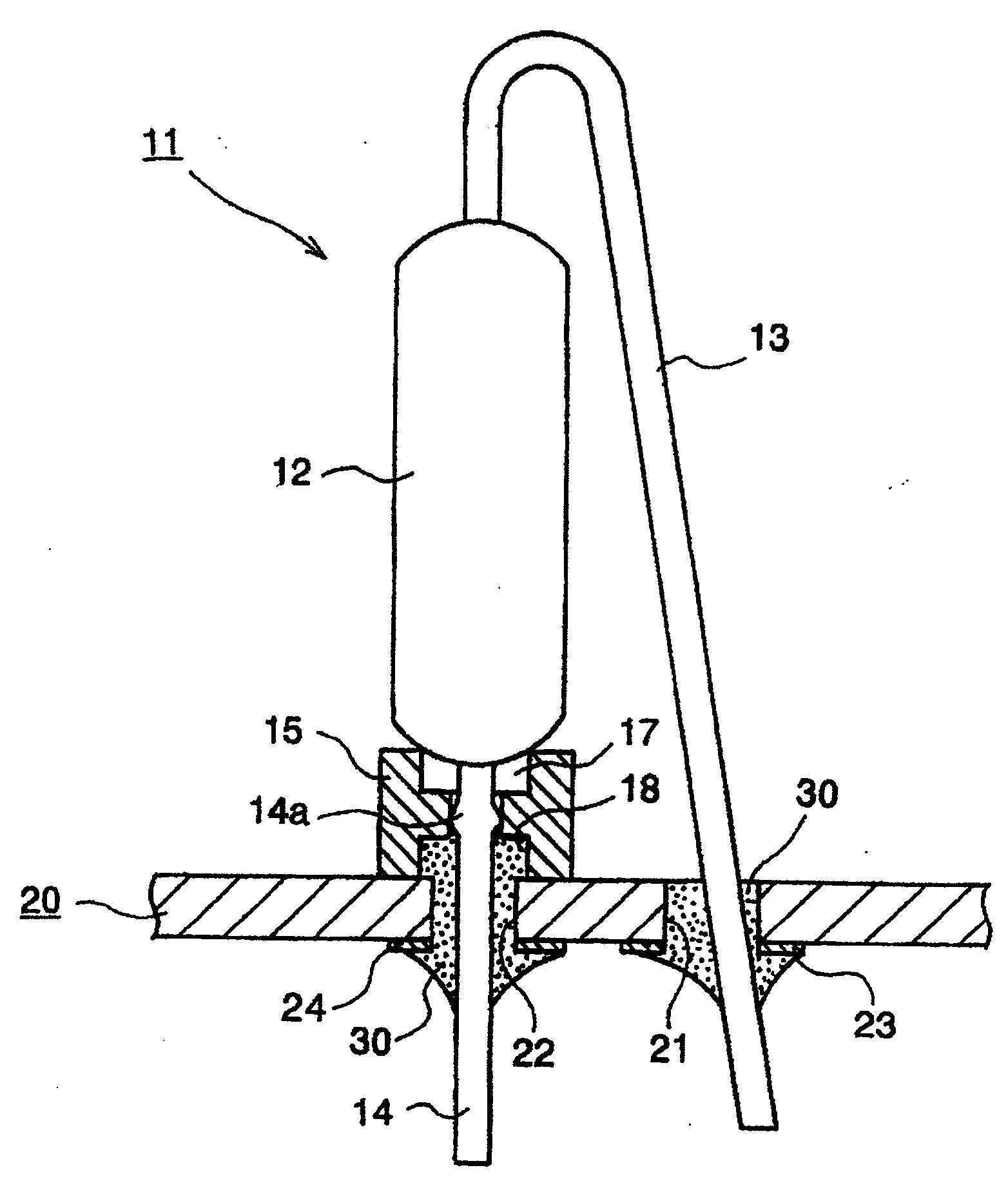
图1是表示本发明的实施例的带导线的电阻器的安装状态的局部剖面图。FIG. 1 is a partial cross-sectional view showing a mounted state of a leaded resistor according to an embodiment of the present invention.
图2是图1所示的支架的俯视图。FIG. 2 is a top view of the bracket shown in FIG. 1 .
图3是该支架的截面图。Fig. 3 is a cross-sectional view of the bracket.
图4是原有技术的带导线的电阻器的立体图。Fig. 4 is a perspective view of a prior art resistor with leads.
具体实施方式 Detailed ways
以下参照附图来说明发明的实施方式。图1是表示本发明的实施例的带导线的电阻器的安装状态的局部剖面图。图2是图1所示的支架的俯视图。图3是该支架的截面图。Embodiments of the invention will be described below with reference to the drawings. FIG. 1 is a partial cross-sectional view showing a mounted state of a leaded resistor according to an embodiment of the present invention. FIG. 2 is a top view of the bracket shown in FIG. 1 . Fig. 3 is a cross-sectional view of the bracket.
图1所示的带导线的电阻器11由略圆柱状的电阻器主体12,突出于该电阻器主体12的两端而设置的一对导线端子13、14,以及陶瓷(例如,块滑石)制成的耐热性的支架15所构成。由线材构成的导线端子13、14之中,一个导线端子13被弯曲成U字形,另一个导线端子14穿过支架15的中央孔16(参照图2、3)。在该导线端子14上通过压溃(つぶし)加工形成展宽部14a,通过将展宽部14a压入支架15的中央孔16内,支架15被安装在电阻器12的一端。另外,在支架15的上下两面形成与中央孔16的两端连通的一对凹部17、18。两凹部以相同的形状形成,电阻器主体12的一端被插入其中一个凹部17内。The leaded
在将这样做构成的带导线的电阻器11安装到线路板20上时,首先,将一对导线端子13、14的各前端部穿过线路板20的对应的导线安装孔21、22,将支架15搭载到线路板20上。还有,在线路板20的背面,在导线安装孔21、22的周围形成有焊环23、24。其次,通过浸渍焊接法或回流焊接法将导线端子13和焊环23焊接起来,同时,将导线端子14和焊环24焊接起来。在该焊接过程中,附着在焊环23上的焊锡30以溶化状态浸入导线安装孔21内,附着在焊环24上的焊锡30以溶化状态浸入导线安装孔22内,由于浸入该导线安装孔22内的溶化的焊锡30浸入凹部18内而附着在导线端子14的基端部。这样,通过焊接,两个导线端子13、14就与相应的焊环23、24电以及机械地连接,由于电阻器主体12成为被支撑在线路板20上的支架15上的状态,所以带导线的电阻器11就以稳定的姿势安装在线路板20上。When mounting the
这样,在本实施方式中,支架15附属设置在电阻器主体12的一端,以该支架15介于竖立姿势的电阻器主体12和线路板20之间而设置的状态安装带导线的电阻器11,在该安装状态,由于电阻器主体12的一端被插入支架15背对线路板20一侧的凹部17内,所以能够以支架15承受作用于线路板20上的电阻器主体12上的外力,而得到十分大的独立强度。另外,由于支架15在线路板20侧的凹部18与导线安装孔22对向,从而在焊接过程中浸入导线安装孔22内的溶化焊锡浸入凹部18内而附着在导线端子14的基端部,因而焊接强度得到提高而使独立的强度进一步提高。并且,由子附属设置在电阻器主体12一端支架15也可以是直径小且低矮的部件,从而不会有因该支架15而损坏空间系数的担心。In this way, in this embodiment, the
还有,由于支架15通过压入导线端子14的展宽部14a来安装到电阻器主体12的一端,该带导线的电阻器11能够在安装前简单地将支架15安装在电阻器主体12上而使得其易于组装,并且,在安装时由于电阻器主体12和支架15能够作为一体部件来处理,从而作业效率良好。但是,即使在安装前支架15和电阻器主体12不一体化,在安装时使支架15介于电阻器主体12和线路板20之间而设置的话,也能够大幅提高带导线的电阻器11的独立强度并且也不损坏空间系数。Also, since the
另外,在本实施方式中,由于支架15是由散热性好的陶瓷制的,不用担心因电阻器主体12所发的热量而使支架15温度过高,从而不用担心支架15的发热对周围的焊锡等产生不良影响。In addition, in this embodiment, since the
另外,在本实施方式中,由于形成于支架15的凹部17、18形状相同,从而该支架15上下没有区别组装而组装性良好。但是,也可以使用凹部17和凹部18形状不同的支架。In addition, in this embodiment, since the
Claims (7)
Applications Claiming Priority (3)
| Application Number | Priority Date | Filing Date | Title |
|---|---|---|---|
| JP2003-298816 | 2003-08-22 | ||
| JP2003298816 | 2003-08-22 | ||
| JP2003298816A JP2005072193A (en) | 2003-08-22 | 2003-08-22 | Resistor with lead and its mounting structure |
Publications (2)
| Publication Number | Publication Date |
|---|---|
| CN1585048A CN1585048A (en) | 2005-02-23 |
| CN100428373C true CN100428373C (en) | 2008-10-22 |
Family
ID=34404206
Family Applications (1)
| Application Number | Title | Priority Date | Filing Date |
|---|---|---|---|
| CNB2004100584979A Expired - Lifetime CN100428373C (en) | 2003-08-22 | 2004-08-19 | Mounting structure of resistors with lead wires |
Country Status (2)
| Country | Link |
|---|---|
| JP (1) | JP2005072193A (en) |
| CN (1) | CN100428373C (en) |
Families Citing this family (1)
| Publication number | Priority date | Publication date | Assignee | Title |
|---|---|---|---|---|
| JP2007317688A (en) * | 2006-05-23 | 2007-12-06 | Sony Corp | Electronic component and electronic component mounting method |
Citations (3)
| Publication number | Priority date | Publication date | Assignee | Title |
|---|---|---|---|---|
| JPH01115291A (en) * | 1987-10-29 | 1989-05-08 | Nec Home Electron Ltd | Rgb multi-terminal input type sequential scanning conversion television receiver |
| JPH02265204A (en) * | 1989-04-05 | 1990-10-30 | Nec Corp | Vertical mounting-type resistor |
| JPH04177801A (en) * | 1990-11-13 | 1992-06-25 | Sony Corp | Electric resistor for vertical type mounting and mounting method therefor |
-
2003
- 2003-08-22 JP JP2003298816A patent/JP2005072193A/en active Pending
-
2004
- 2004-08-19 CN CNB2004100584979A patent/CN100428373C/en not_active Expired - Lifetime
Patent Citations (3)
| Publication number | Priority date | Publication date | Assignee | Title |
|---|---|---|---|---|
| JPH01115291A (en) * | 1987-10-29 | 1989-05-08 | Nec Home Electron Ltd | Rgb multi-terminal input type sequential scanning conversion television receiver |
| JPH02265204A (en) * | 1989-04-05 | 1990-10-30 | Nec Corp | Vertical mounting-type resistor |
| JPH04177801A (en) * | 1990-11-13 | 1992-06-25 | Sony Corp | Electric resistor for vertical type mounting and mounting method therefor |
Also Published As
| Publication number | Publication date |
|---|---|
| CN1585048A (en) | 2005-02-23 |
| JP2005072193A (en) | 2005-03-17 |
Similar Documents
| Publication | Publication Date | Title |
|---|---|---|
| US7791901B2 (en) | Stand-off mounting apparatus for discrete electrical components | |
| US20100090792A1 (en) | Thermally decoupling fuse holder and assembly | |
| US6994565B2 (en) | Electrical contact assembly with insulative carrier, stapled contact attachment and fusible element | |
| JP2007141570A (en) | Mounting structure of female connector | |
| US4559514A (en) | Chip type fuse having connecting legs | |
| JP2002009217A (en) | Resin-sealed semiconductor device | |
| JP3751472B2 (en) | Double-sided pattern sheet metal parts and printed wiring board | |
| CN100428373C (en) | Mounting structure of resistors with lead wires | |
| US5698819A (en) | Surface mount electronic reed switch component | |
| JPH07307545A (en) | Substrate for mounting electronic components of surface mount type and clip lead frame | |
| JP2003187890A (en) | Electrical connection terminal | |
| JP3242858B2 (en) | Connector and manufacturing method thereof | |
| JPH0642371Y2 (en) | Hybrid integrated circuit device | |
| JPH10177901A (en) | Electronic part | |
| JPH0745977Y2 (en) | Board connection structure | |
| JPH0519985B2 (en) | ||
| CN104303296A (en) | Circuit assembly | |
| JP2006108909A (en) | Base for electronic elements | |
| JPH0585051U (en) | IC package | |
| JPH0456295A (en) | Mounting method for electronic component | |
| JPH0656977U (en) | PCB connector | |
| JPS60160640A (en) | Ic socket | |
| JPH04116369U (en) | Grommets to prevent poor connections | |
| JP2003249737A (en) | Connection structure between board and terminal | |
| JPS63313477A (en) | Electrical connection terminal |
Legal Events
| Date | Code | Title | Description |
|---|---|---|---|
| C06 | Publication | ||
| PB01 | Publication | ||
| C10 | Entry into substantive examination | ||
| SE01 | Entry into force of request for substantive examination | ||
| C14 | Grant of patent or utility model | ||
| GR01 | Patent grant | ||
| CX01 | Expiry of patent term |
Granted publication date: 20081022 |
|
| CX01 | Expiry of patent term |