Summary of the invention
The small digital cameras of structure is communication device or other the compact equipment that is used to move.Such camera optics system can include the micro objective assembly that single or multiple lenticular units are formed.This optical system will send transducer series to from the image that external light source is accepted, and this series converts optical signalling to digital signal and handles.In the structure of a plurality of lens, each lens move relative to one another so that the ability of automatic focus and zooming is provided in the optical system.
In the simplest application, can make single main lens that enough moving so that provide automatic focus according to detected target location arranged.Yoke will at first be described the present invention with reference to the application of single adjustable lens for the sake of simplicity, although adopt a plurality of driving mechanisms can construct the structure of a plurality of lens as disclosed in this application.
According to this invention, lens element is installed in the camera on the tube assembly.Successively lens tube is installed on the stay pipe so that move along the longitudinal axis of tube assembly.By a plurality of bimorph cells, for example be provided with around the symmetrical compartment of terrain of the circumference of stay pipe and provide adjustable mobile with 3 elements.Piezoelectric element is connected to and is installed on the flexible printed circuit board (PCB), and this circuit board can comprise other electronic units that are associated with lens drive system.Flexible printed circuit board is installed on the stay pipe and is connected to successively voltage source such as battery.The flexible of printed circuit board (PCB) allows it can form the shape of stay pipe to contact with piezoelectric element is navigated to lens tube.
The bimorph cell of using in subject mechanism is to be formed by at least two layer of piezo-electric material structures, and two layer materials are independently-powered so that produce relative deformation between two layers.The piezoelectric element of using in the system of an embodiment of this invention is the shape that forms beam, has contact mat from its mid point the flat transverse of element to be stretched.Beam is fixed on circuit board near terminal or site position.The outer end of contact mat can move freely, and operationally links to each other with lens tube movably.In a preferred embodiment, this beam comprises a pair of bimorph cell that extends in these contact mat both sides.Each bimorph has two active layers.To cause the piezoelectric element bending by the different distortion that only one deck power supply in two layers is produced, the outer end of contact mat is moved into and the contacting of removable lens tube.By changing the excitation of piezoelectric element, cause contact mat moving axially, thereby regulate the position of lens.The pattern of design excitation is so that produce moving of discrete step.
Processor being connected to printed circuit board (PCB) so that provide the main control and the processor of structure to digital camera is to produce driving voltage waveform according to the required motion of lens.
Provide very high resolution by the mobile of piezoelectric element generation, but do not have structure member that reference marker is provided in order to obtain accurate repeatability.The step-length that can provide by piezoelectric element by the condition changing of operation and environment.In order to obtain precision required in some optical design, the application site sensor is monitored the position of movable tubes.The applied optics sensor is observed the reflecting surface that is installed on the movable tubes.Reflecting surface comprises the gray scale that is incorporated in the movable tubes surface treatment.This structure will provide movable tubes accurate position monitoring.
In second embodiment of this invention, adopt a pair of lens so that the function of varifocal is provided.In this embodiment movable tubes is divided into front lens support section and rear lens support section and by piezoelectric element with above-mentioned similar methods drive respectively each the section.Since should use verifiedly, can optical sensors monitor two sections position.
Each embodiment of all right tectonic association automatic focus and zoom function.
Installing small-sized drive system by this way comes the lens in the mobile camera that the consumption of electric power and occupation space are minimized.
Description of drawings
Describe the present invention below with reference to the accompanying drawings in detail, accompanying drawing has:
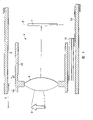
Fig. 1 is the synoptic diagram that is applied in simple optical system in the digital camera according to the preferred embodiment of this invention;
Fig. 2 is the sectional view of getting along profile line a-a that is illustrated in the optical system of this invention among Fig. 1;
Fig. 3 is the calcspar according to the digital camera control system of this invention preferred embodiment;
Fig. 4 a-4e is the enlarged drawing that is illustrated in piezoelectric element among Fig. 1 and 2 under various incentive conditions;
Fig. 5 is the decomposition diagram of each parts of optical system of this invention;
Fig. 6 is the synoptic diagram of another embodiment of this invention optical system;
Fig. 7 is the end-view that is illustrated in this invention optical system among Fig. 6; With
Fig. 8 is the schematic illustration of another embodiment of piezoelectric element of adopting in the embodiment of Fig. 6 and 7;
Fig. 9 a and 9b have removable lens module so that provide automatic focus and the synoptic diagram of the potential optical system of two kinds of functions of zooming;
Figure 10 is the synoptic diagram that drives the circuit of bimorph cell;
Figure 11 is the constructed profile that adopts another embodiment of optical system of position transducer according to this invention expression;
Figure 12 a is the exploded view of primary element of another embodiment of Figure 11;
Figure 12 b is the sectional view that the embodiment that assembles of Figure 12 a gets along the axle profile line;
Figure 12 c is the sectional view that the embodiment that assembles of Figure 12 a gets along the profile line of this device axis of crosscut;
Figure 13 is the constructed profile that the optical system of this invention also has an embodiment;
Figure 14 (a) is that the spring of the embodiment of Figure 13 supports and the perspective illustration of flexible printed circuit board (PCB);
Figure 14 (b) is the spring of embodiment of Figure 13 and the schematic end view of flexible printed circuit board assembly;
Figure 15 is the perspective illustration of movable pipe of the embodiment of Figure 13; With
Figure 16 is the perspective illustration that this invention has the optical system stay pipe of position monitor.
Embodiment
The general optical lens system 1 that automatic focus ability camera is arranged has schematically been described in Fig. 1.Usually it will comprise main lens 2, and its operation projects the focusedimage of object 8 on the plane of delineation 5.As shown in the figure, main lens 2 is adjustable in the X-Y zone.As shown in FIG. 3, in digital camera system 6, use lens combination 1.Lens combination 1 is fixed in the housing (not shown), so as with image projection on the imageing sensor 7 of the plane of delineation 5 that is positioned camera system 6.Main lens 2 is adjustable so that obtain auto-focus function.Select single adjustable lens arrangement for convenience of description.Should be realized that can to obtain a plurality of lens adjustable so that the ability of varifocal is provided.The example of the such system of expression in Fig. 9 a and 9b.In the latter case, can set up a plurality of piezoelectric drive groups so that provide automatic focus and the motion of the independent regulation of zoom lenses.
Lens arrangement body 1 as shown in FIG. 1 comprises stay pipe 9 and lens tube 10.Lens tube 10 clamping lens 2 also are installed in the stay pipe 9 by coaxial.Lens tube 10 is adjustable so that the automatic focus ability of camera system 6 is provided.For necessary adjusting is provided, lens tube 10 is supported on carries out axial motion in the stay pipe 9.As shown in Fig. 1 and 2, provide the support and the motion of lens tube 10 by a plurality of bimorph cells 11,12 and 13.If do not need very big axial force so can by two or even an element drive lens tube.
The circuit board that is used for Piezoelectric Driving is flexible printed circuit board (PCB) 14, and it is around the outer cylinder surface setting of stay pipe 9.Parts that piezoelectric element 11-13 is relevant with their directly are connected and are supported on the flexible circuit board 14.As shown in FIG. 3, by different printed circuit board supports and being connected on the Flame Image Process and related elements of camera system 6, as element 73 expressions of reference number among Figure 12.Power supply supply 22 will be connected to printed circuit board (PCB) 14 and 73 with well-known method as battery.Around the flexible insulating trip 15 of flexible circuit board 14 parcels.Be clamped on the position of stay pipe 9 by the wound spring 16 that splits assembly flexible circuit board and insulating trip 15.By cancelling damping fin 15 and spring 16 in the structure that these functions is attached to flexible circuit board 14.On flexible circuit board 14, form contact 20 so that the path that connects flexible circuit board 14 and power supply supply 22 is provided.Sheet 15 produces the noise that flexible damping allows the essential bending and the decay sense of hearing simultaneously again to piezoelectric deforming in assembly.
As shown in Fig. 1 and 2, piezoelectric element is installed in flexible circuit board 14 on stay pipe 9 neighborings.Element 11-13 is identical, and each all is to constitute with a pair of element 31 and 30, as shown in Fig. 4 e.Element 11 is made up of bimorph sections 30 and 31, and by the passive components 32 at the beam mid point they being linked together constitutes beam.Contact mat 33 is protruding to axis from the level of passive components 32 crosscut beams.Bimorph sections 30 is to be made of two piezoelectrics 30A and 30B, and two piezoelectrics all are active and are connected to flexible circuit board 14 by contact 34.Each piezoelectrics can comprise be connected to each other and polarize which floor in case its effect as a piezoelectric layer.Can reduce essential driving voltage like this.If corresponding distortion enough can also only be used piezoelectrics in each bimorph sections.Identical section 31 is to be made of two piezoelectric layer 31A and 31B, and they are connected to flexible circuit board 14 by contact 35.Contact mat 33 under confined state with stay pipe 9 in opening 18 align so that pad 33 external contravention 36 is contacted with lens support tube 9.
Encourage piezoelectric element 11-13 in predetermined patterns so that the connecting rod 33 that makes element 11-13 and lens tube 10 contact and regulate its axial location.The amount of this adjusting will be determined the distance of this sensor object 8 according to the signal from automatic focus sensor 23.Use suitable algorithm, might be directly obtain self-focusingly to give given data, thereby no longer need the sensor element that separates from imageing sensor.Providing a plurality of lens movements so that have under the situation of zoom function, installing manual zooming control 24, so that send the motion that signal causes zoom lens, as shown in Fig. 9 a to camera control processor.Camera system 6 comprises main processing controller 21, and it is supplied with 22 from power supply and accepts electric power so that the parts of drive system 6.Provide conditioning signal by the automatic focus sensor 23 apart from d between inspected object and the optical system 1.
Camera control processor 21 produces signal and it is delivered to actuator processor controls 25.Actuator processor controls 25 produces the expectant control voltage modes, so that the piezoelectric element response is out of shape from the signal of camera control processor 21.The design voltage pattern makes adjustable lens pipe 10 in the instruction of axial amount of movement according to automatic focus sensor 23.Optical element with the image projection of object 8 to the imageing sensor 7 that is positioned at camera system 6 focussing planes 5.Imageing sensor 7 produces indication by the signal of projects images.In image processor 26, convert picture signal to digital signal.Data image signal is stored in the memory paragraph of camera control processor 21.
An example of expression actuator processor controls 25 in the circuit diagram of Figure 10.Circuit shown in the design goes to control two piezoelectric elements 201 and 202.Comprise the output electric bridge 210 of transistor 211,212,213,214 by driving, control piezoelectric element 201 and another electric bridge that separates 220 that comprises transistor 221,222,223,224 by driving, control another piezoelectric element 202. Electric bridge 210 and 220 transistor can be or device bipolar or field effect (FET); Perhaps their combination.Control electric bridge 210 and control electric bridge 220 by electric bridge control signal 231,232,233,234 by signal 241,242,243,244. Electric bridge 210 and 220 transistor can or discrete or be integrated in the control circuit.The ground connection of 0 indicating circuit and+indication supply line.In operation can control half electric bridge comprising transistor 211 and 212 by electric bridge control signal 231,232 so as output 0 and+between any voltage and by electric bridge control signal 233,234 can control comprise transistor 213,214 half electric bridge 210 in addition so that the complementary voltage of output.
Therefore can the voltage of whole supply line be added in element 201 with any mode.Control signal 231,232,233,234 can also be set at an easy rate turn off all crystals pipe in electric bridge 210 fully.Controller 25 can be controlled electric bridge 220 and comes output voltage to element 202 or element 202 is disconnected in any mode in an identical manner.Application controller 25 is by controlling the motion that two or more elements can be realized all required piezoelectric elements simultaneously respectively.
Fig. 4 a-4e represents double-deck bimorph cell 11, and its structure is to contact so that regulate the axial location of lens tube 10 with lens tube 10.As described earlier, element 11 and its related elements 12 with 13 each be with identical method construct.In each element 11, a pair of bimorph cell 30 and 31 is mechanically to link together by passive part 32 to constitute beam 4.The structure of each section is identical, so only describe one.Bimorph sections 30 comprises two active part 30A and 30B, and they are separated by the electrode 34A of centre.Represent active part 30A with the form of individual layer, but the structure of multilayer can be arranged.Similarly, following active part 30B can comprise many piezoelectric layers, but in order simply only to represent one deck.Hearth electrode (34C) with active part 30B is connected to GND (ground connection) in one embodiment.(34A-C 35A-C) can control separately all in another embodiment electrodes.If use soft piezoelectric, i.e. the material of a kind of easy polarization makes the voltage that is connected to active part 30A top electrode be higher than the crest voltage that is added to signal electrode 34A so.If use hard piezoelectric, can use the polarization opposite with electric field also can be with top electrode ground connection.
By between selected electrode, adding voltage, can encourage active part 30A and 30B respectively.By add voltage on active part 30A, piezoelectric layer expands on direction of an electric field, i.e. every layer of thickening, if but electric field and polarize identical direction is arranged simultaneously, active part 30A will shrink in the vertical so.This pucker ﹠ bloat is relevant with the characteristic coefficient of selected piezoelectric.If active part 30A is constant when excitation active part 30B, the length of active part 30B reduces to cause bimorph sections 30 distortion and is bent upwards, as shown in Fig. 4 a.By in section 31, putting upside down this excitation, obtain opposite distortion, this will cause beam 4 as in the distortion as shown in Fig. 4 a.As shown in Fig. 4 a-d, obtain a kind of pattern that encourages and be out of shape so that each step of motion is provided.Can repeat to excite these steps by appropriate signal.
As shown in Fig. 4 e, bimorph cell 11 comprises two the adjacent piezoelectric beams or the section 30 and 31 of being separated by passive part or parts 32.Element 11 has 3 contact points, and one and another contact jaw 36 at pad 33 is respectively arranged at the two ends of combination beam.For the whole beam that allows each beam section and comprise element 11 has required distortion, the terminal of beam should be installed in flexiblely on the flexible circuit board 14, so that provide to a certain degree rotation at corresponding contact point.
So independently active part 30A, 30B, 31A and 31B form beam 4 by 4.1 to 4 dynamic excitation makes contact mat 33 produce motion at Z and X both direction in 4 active parts.By the cooperation of active part excitation, obtain the motion that in Fig. 4 a-4d, illustrates.Notice that the motion of all piezoelectric elements is all exaggerated in the drawings, only for the principle of account for motion.This provides contact mat 33 disciform motions under ultrasonic frequency, and this will make lens support tube move on directions X.
In on Dec 20th, 2000 application, in the U.S. Patent Application Serial Number 09/739,906 of common pending trial this class piezoelectric drive element has been described.The disclosure of this application all is included in here as a reference.
In another embodiment shown in Fig. 6-8, the semi-girder that two active part 40A that piezoelectric element 11A comprises that passive part 42 supports and 40B form, passive part is installed on the flexible circuit board 14.Piezoelectric element 11A has at least two parallel active part 40A and 40B.Each active part 40A and 40B comprise at least one layer of piezoelectric layer.Can activate active part 40A and 40B respectively by the electrode 43 (only representing in the drawings) that be arranged in parallel with active part 40A and 40B.At the movable tip 45 of piezoelectric element 11A are surface in contacts 48, and surface in contact is contacted with adjustable pipe 10.Flexible circuit board 14 is at passive part 32 support component 11A, and is connected to electrode 43 by suitable mechanism's (not shown).In this embodiment, flexible circuit board 14 is fixed on the inside surface 15 of stay pipe 9.Stay pipe 9 is fixed on (not shown) in the main body of camera system 6.
By on two active part 40A and 40B, applying identical voltage, can make element 11A in axial shrinkage.By on each active part 40A and 40B, applying the different voltages of combination, can be in two-dimensional space (X and Z) mobile drive surfaces 48, elliptical path explanation as shown in FIG. 8 like that.For mobile adjustable tube 10, force element 11A bending to press to it and carry out rubbing contact.Can carry out the active part 40A excitation different with 40B so that element 11A is expanded, this will cause adjustable tube 10 in opposite moving axially.
In any embodiment, by deriving the pattern that will be added to the voltage signal on piezoelectric element 11 electrodes, can obtain the required mode of the motion consistent with required function.Performed special exercise is the signal of response from camera control processor 20.
In order to obtain precision required in some optical design, as shown in Figure 11 and the 12a-c, use location sensor 70 is monitored the position of movable tubes.The optical system of this embodiment comprises foregoing stay pipe 17 and lens tube 10 movably.These parts are directly installed on the printed circuit board (PCB) 73 by clamper 74 (seeing Figure 11).Printed circuit board (PCB) 73 comprises imageing sensor 7, image processor 26 and relevant parts (not shown).Optical sensor 71 is installed and is connected flexible circuit board 14 and uses this sensor to observe the reflecting surface 76 that is installed on the movable tubes 10.Optical sensor 71 can be small-sized, reflection-type, optical chopper commercial sale, inferior, as model GP2S60, from U.S. Camas, the Sharp Micxoelectronics company of WA is on sale.Optical monitoring device 70 comprises that as at the reflecting surface 76 as shown in the embodiment of Figure 15, it comprises the gray scale that is incorporated in the movable tubes surface treatment.In Figure 15, in the back segment 120 of movable tubes 110, represent reflecting surface 76.The assembly of this embodiment also comprise around stay pipe 17 parcel and be clamped in locational flexible circuit board 14 by spring element 16.The contact mat of these elements piezoelectric element 1-13 is installed in a position on the flexible circuit board 14, so that can be contacted with lens tube 10 by the opening 76-78 in the stay pipe 17.The passage of virtual location sensor 71 is provided by the mouth 79 in the stay pipe 17.This structure will provide movable tubes to monitor accurately in various embodiment.In the plug-in package of optical system 1, must provide suitable openings, so that make optical sensor 51 that the passage of visual movable tubes 10 or 110 (in Figure 13) can be arranged.
Above-mentioned piezo driven systems can be fit to move a plurality of lens at an easy rate, perhaps by providing required controllability to the suitable connected system of single driving or by a plurality of drivings independently so that for automatic focus and two kinds of abilities of zooming.Fig. 9 a and 9b represent two kinds of possible lens arrangements that automatic focus and zoom function are provided.In the system of Fig. 9 a, main lens 51 is installed in the motion that is used for relative focussing plane 5 on the stay pipe, installing comprises the zoom assembly of a pair of lens 52 and 53.Zoom lenses is installed to be used for moving relative to main lens 51 and focussing plane 5.Zooming also is installed to be regulated being used for moving forward into line focusing with main lens.Design this system and carry out the motion that main lens supports so that applying piezoelectric drives, it can comprise that the zooming parts drive with second so that the zoom lenses motion that relative main lens supports is provided.
The a pair of lens 61 of the zooming system applies of in Figure 96, representing and 62.This structure also can be fit to carry out as in the motion in 63 and 64 in the zone as shown in Figure 96 as above-mentioned a pair of driving.In these structures, can install the second movable stay pipe, it is installed be used for moving in primary lens support tube 10.In general, provide zoom function, install two groups of lens at least, one group is used to regulate the variation that zooming ratio and another group are used for compensating focusing.Expression provides the piezoelectric driven optical system of zoom function in Figure 13-15.According to the needs of application-specific, there is the structure of countless lens combinations can be fit to the system of this invention.Each system described herein is designed for the various application that its size, weight and consumed energy all need to reach minimum.
In Figure 13-16, in a plurality of lens combinations of the embodiment of expression, optical system 101 is directly installed on the main printed circuit board 122 that comprises the imageing sensor (not shown).First lens element 103 that comprises first lens element 102 and band Infrared filter 104 in the optical system 101 shown in Figure 13-15.Optical system 101 is installed on the movable tubes 110.In this structure, movable tubes 110 is divided into two sections, the leading portion 121 of first lens element 103 and the back segment 120 of installation second lens element are installed.Each section of movable tubes 110 can move mutually.For example, as shown in Figure 15, leading portion 121 can move on back segment 120.Also leading portion 121 can be connected to corrugated tube 105 and provide sealing for optical system 101.
As shown in Figure 14 b, every section of movable tubes 110 by a pair of piezoelectric element drive, and piezoelectric element 112 and 113 can drive back segment 120 and piezoelectric element 111 and 131 can drive leading portion 121.In order to increase the contacting efficiency with Piezoelectric Driving, on leading portion 121 and back segment 120, construct the surface in contact 125 and 126 of actuator pad respectively.Can form each contact mat by changing surface smoothness at correct position.
Be in this embodiment every section 120 and 121 can optical sensors, as 123, it is directly installed on the flexible printed circuit board (PCB) 114.Structure opening 127 in stay pipe 117 is so that provide the optical exposure mouth for the reflecting surface 76 of back on the pipeline section 120.
A kind of general driving mechanism is provided by this way, and it satisfies the every designing requirement to space, power consumption and weight.Concerning the general technical staff of the technical field of the invention, can understand, can carry out various modifications and change to each above-mentioned embodiment and can not deviate from by the defined category of the present invention of claims.