CN100420416C - Separator with multi-air intake and dust cup device thereof - Google Patents
Separator with multi-air intake and dust cup device thereof Download PDFInfo
- Publication number
- CN100420416C CN100420416C CNB2006100779730A CN200610077973A CN100420416C CN 100420416 C CN100420416 C CN 100420416C CN B2006100779730 A CNB2006100779730 A CN B2006100779730A CN 200610077973 A CN200610077973 A CN 200610077973A CN 100420416 C CN100420416 C CN 100420416C
- Authority
- CN
- China
- Prior art keywords
- separator
- cup
- air intake
- air
- dust
- Prior art date
- Legal status (The legal status is an assumption and is not a legal conclusion. Google has not performed a legal analysis and makes no representation as to the accuracy of the status listed.)
- Active
Links
Images


Abstract
A separator with multiple air inlets for increasing the dusting efficiency of cleaner is composed of an upper cylinder and a lower conic barrel, which are coaxial, an air outlet arranged coaxially in said cylinder, and two air inlet tubes, which has involute central line and rectangular cross-section and is connected to the lateral wall of cylinder at same height. A dusting cup unit with said separator is also disclosed.
Description
Technical field
The present invention relates to a kind of multi-air intake separator and contain the cup device for dust of this device.
Background technology
State Intellectual Property Office on March 5th, 2003 Granted publication a name be called " speed reducing centrifugal duster for cleaner ", the patent No. is the patent of invention of ZL02220336.2, this patent disclosure " a kind of speed reducing centrifugal duster for cleaner; comprise the circular cylinder body that connects successively from top to bottom; conical shell and dust-collecting box; discharge pipe on the circular cylinder body and blast pipe; described conical shell upper end is little; the lower end is big, the below that is positioned at discharge pipe in the conical shell is provided with the umbrella shape reflecting disc, the center of umbrella shape reflecting disc is provided with return port, is provided with the dust fall annular space between the periphery of umbrella shape reflecting disc and the sidewall; The atmospheric pressure lost of this device is little, pick-up performance good, filter dirt precision height, operating noise is low, can avoid the secondary pollution of air effectively, is specially adapted to cascade filtration system, the separation fine dust of dust catcher.”
Because above-mentioned separator has only an air inlet, therefore, the area of air inlet is difficult to enlarge, and has become the main cause that restriction dust catcher air quantity improves.
Summary of the invention
The objective of the invention is: a kind of multi-air intake separator is provided and contains the cup device for dust of this device, can increase the incoming air area of dust catcher, improve the efficiency of dust collection of dust catcher.
Technical scheme of the present invention is: a kind of multi-air intake separator, and comprise cylindrical shell, be arranged on discharge pipe and blast pipe on the cylindrical shell, described blast pipe is provided with two at least; Described cylindrical shell comprises circular cylinder body and the conical shell that connects up and down, and discharge pipe is arranged in the circular cylinder body coaxially, and blast pipe is connected on the sidewall of circular cylinder body; The height and position of described two blast pipes on circular cylinder body is identical, circumferential position staggers 180 °, and their air inlet is positioned at through the same plane of the axis of circular cylinder body and towards on the contrary; The center line of described two blast pipes is involute shape; The longitudinal cross-section of described two blast pipes is a rectangle.
A kind of cup device for dust that contains the multi-air intake separator, comprise bowl cover and cup, bowl cover is provided with air outlet, cup is provided with air inlet, the primary dust removing device is installed in the cup, be provided with secondary device in one stage arrangement, described primary dust removing device is a filtering screen, the two-stage dust removal device is the multi-air intake separator, the upper port of filtering screen is cut off by the upper spacer between bowl cover and the cup, the lower port of filtering screen is by the sealing of the lower clapboard of multi-air intake separator periphery, and the blast pipe of multi-air intake separator is positioned at filtering screen, discharge pipe passes upper spacer and is communicated with air outlet on the bowl cover.
Advantage of the present invention is:
1. the present invention has increased an air inlet on the basis of existing separator, to increase incoming air area, air quantity is significantly increased than existing apparatus, has also improved the efficiency of dust collection of dust catcher simultaneously.
2. the present invention adopts two involute air inlet pipe, under the situation of same inlet-duct area and import debugging, entrance width can reduce, the decentre district was far away when dust-contained airflow entered the dust arrester body, under same action of centrifugal force, it is short more that dust is shifted to the distance of wall, favourable more to separative efficiency.
Description of drawings
The invention will be further described below in conjunction with drawings and Examples:
Fig. 1 is the front view of prior art;
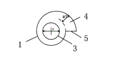
Fig. 2 is the vertical view of circular cylinder body among Fig. 1;
Fig. 3 is a front view of the present invention;
Fig. 4 is the vertical view of circular cylinder body among Fig. 3;
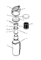
Fig. 5 is the installation diagram of cup device for dust;
Fig. 6 is the outside drawing of cup device for dust.
Wherein: 1 circular cylinder body; 2 conical shells; 3 discharge pipes; 4 blast pipes; 5 air inlets; 6 bowl covers; 7 cups; 8 air outlets; 9 air inlets; 10 filtering screens; 11 multi-air intake separators; 12 upper spacers; 13 lower clapboards.
The specific embodiment
Embodiment: as shown in Figure 3, Figure 4, a kind of multi-air intake separator, comprise up and down the circular cylinder body 1 that connects and conical shell 2, the coaxial discharge pipe 3 that is arranged on circular cylinder body 1 inside, the sidewall of described circular cylinder body 1 is connected with that two center lines are involute shape, the longitudinal cross-section is the blast pipe 4 of rectangle, the height and position of two blast pipes 4 on circular cylinder body 1 is identical, circumferential position staggers 180 °, their air inlet 5 is positioned at through the same plane of the axis of circular cylinder body 1 and towards on the contrary.
As shown in Figure 1 and Figure 2, in existing apparatus, the width of blast pipe 4 is a
1, highly be b, area is m
1=a
1* b, m
1Become the bottleneck of restriction air quantity in the device, prerequisite is m
1Area π r less than discharge pipe 3
2, this is by the decision of the modeling structure of dust catcher.
As shown in Figure 3, Figure 4, in order to strengthen incoming air area, the present invention adopts two air feeder structures, incoming air area m
2=2a
2* b has increased incoming air area than existing apparatus, simultaneously, if m
2Area π r greater than discharge pipe 3
2, then air outlet becomes the bottleneck of device, under the prerequisite that guarantees efficiency of dust collection, increases the diameter of discharge pipe 3, also can improve the air quantity of device.
In addition, under the situation of same inlet-duct area and air inlet pipe height, a
2Can reduce, i.e. a
2The a that has only
1Half when this just makes dust-contained airflow enter the dust arrester body, can help improving efficiency of dust collection away from the gas outlet, center.
As Fig. 5, shown in Figure 6, a kind of cup device for dust that contains the multi-air intake separator, comprise bowl cover 6 and cup 7, bowl cover 6 is provided with air outlet 8, cup 7 is provided with air inlet 9, the primary dust removing device is installed in the cup 7, be provided with secondary device in one stage arrangement, described primary dust removing device is a filtering screen 10, the two-stage dust removal device is a multi-air intake separator 11, the upper port of filtering screen 10 is cut off by the upper spacer between bowl cover 6 and the cup 7 12, the lower port of filtering screen 10 is by lower clapboard 13 sealings of multi-air intake separator 11 peripheries, and the blast pipe 4 of multi-air intake separator 11 is positioned at filtering screen 10, discharge pipe 2 passes upper spacer 12 and is communicated with air outlet 8 on the bowl cover 5.
Claims (1)
1. cup device for dust, comprise bowl cover (6) and cup (7), bowl cover (6) is provided with air outlet (8), cup (7) is provided with air inlet (9), cup is equipped with the primary dust removing device in (7), be provided with secondary device in one stage arrangement, it is characterized in that: described primary dust removing device is filtering screen (10), the two-stage dust removal device is multi-air intake separator (11), the upper port of filtering screen (10) is cut off by the upper spacer (12) between bowl cover (6) and the cup (7), the lower port of filtering screen (10) is by peripheral lower clapboard (13) sealing of multi-air intake separator (11), and the blast pipe (4) of multi-air intake separator (11) is positioned at filtering screen (10), discharge pipe (2) passes upper spacer (12) and is communicated with air outlet (8) on the bowl cover (5).
Priority Applications (1)
| Application Number | Priority Date | Filing Date | Title |
|---|---|---|---|
| CNB2006100779730A CN100420416C (en) | 2006-04-06 | 2006-04-25 | Separator with multi-air intake and dust cup device thereof |
Applications Claiming Priority (3)
| Application Number | Priority Date | Filing Date | Title |
|---|---|---|---|
| CN200620072211.7 | 2006-04-06 | ||
| CN200620072211 | 2006-04-06 | ||
| CNB2006100779730A CN100420416C (en) | 2006-04-06 | 2006-04-25 | Separator with multi-air intake and dust cup device thereof |
Publications (2)
| Publication Number | Publication Date |
|---|---|
| CN1895146A CN1895146A (en) | 2007-01-17 |
| CN100420416C true CN100420416C (en) | 2008-09-24 |
Family
ID=37607901
Family Applications (1)
| Application Number | Title | Priority Date | Filing Date |
|---|---|---|---|
| CNB2006100779730A Active CN100420416C (en) | 2006-04-06 | 2006-04-25 | Separator with multi-air intake and dust cup device thereof |
Country Status (1)
| Country | Link |
|---|---|
| CN (1) | CN100420416C (en) |
Families Citing this family (5)
| Publication number | Priority date | Publication date | Assignee | Title |
|---|---|---|---|---|
| CN103120572B (en) * | 2013-01-10 | 2016-05-18 | 宁波富佳实业有限公司 | Two air inlet dirt cups and use the dust catcher of this dirt cup |
| GB201311451D0 (en) * | 2013-06-27 | 2013-08-14 | Deregallera Holdings Ltd | Vacuum Cleaner |
| CN104587768B (en) * | 2015-02-24 | 2016-02-03 | 郑应力 | The method that the dedusting of a kind of cleaning machine water and particular pollutant are separated and device |
| CN106166047A (en) * | 2016-08-30 | 2016-11-30 | 苏州市春菊电器有限公司 | A kind of multistage cyclone filters dust cup of dust collector |
| CN107149811A (en) * | 2017-06-27 | 2017-09-12 | 佛山市人居环保工程有限公司 | A kind of equal wind apparatus |
Citations (6)
| Publication number | Priority date | Publication date | Assignee | Title |
|---|---|---|---|---|
| US3969096A (en) * | 1974-10-16 | 1976-07-13 | E. I. Du Pont De Nemours And Company | Cyclone separator having multiple-vaned gas inlets |
| WO1998035601A1 (en) * | 1997-02-13 | 1998-08-20 | Aktiebolaget Electrolux | Cyclone separator for a vacuum cleaner |
| US6398973B1 (en) * | 1997-11-04 | 2002-06-04 | B.H.R. Group Limited | Cyclone separator |
| WO2002069778A1 (en) * | 2001-02-13 | 2002-09-12 | Fortum Oyj | Dust separation method and arrangement of a central vacuum cleaner |
| CN2538270Y (en) * | 2002-04-28 | 2003-03-05 | 苏州金莱克清洁器具有限公司 | Speed reducing centrifugal dusting device for suction cleaner |
| CN1473541A (en) * | 2002-08-19 | 2004-02-11 | 乐金电子(天津)电器有限公司 | Centrifugal vacuum cleaner |
-
2006
- 2006-04-25 CN CNB2006100779730A patent/CN100420416C/en active Active
Patent Citations (6)
| Publication number | Priority date | Publication date | Assignee | Title |
|---|---|---|---|---|
| US3969096A (en) * | 1974-10-16 | 1976-07-13 | E. I. Du Pont De Nemours And Company | Cyclone separator having multiple-vaned gas inlets |
| WO1998035601A1 (en) * | 1997-02-13 | 1998-08-20 | Aktiebolaget Electrolux | Cyclone separator for a vacuum cleaner |
| US6398973B1 (en) * | 1997-11-04 | 2002-06-04 | B.H.R. Group Limited | Cyclone separator |
| WO2002069778A1 (en) * | 2001-02-13 | 2002-09-12 | Fortum Oyj | Dust separation method and arrangement of a central vacuum cleaner |
| CN2538270Y (en) * | 2002-04-28 | 2003-03-05 | 苏州金莱克清洁器具有限公司 | Speed reducing centrifugal dusting device for suction cleaner |
| CN1473541A (en) * | 2002-08-19 | 2004-02-11 | 乐金电子(天津)电器有限公司 | Centrifugal vacuum cleaner |
Also Published As
| Publication number | Publication date |
|---|---|
| CN1895146A (en) | 2007-01-17 |
Similar Documents
| Publication | Publication Date | Title |
|---|---|---|
| CN100336482C (en) | Sectional type dust remover of vacuum cleaner | |
| CN100374065C (en) | Dust-collecting unit of outlay type dust collector | |
| CN100394881C (en) | Parallel type dust removing device of vacuum cleaner | |
| CN1969739B (en) | Dust separation device of vacuum cleaner | |
| CN100376191C (en) | Dust collector whirlwind separating arrangement | |
| CN100577081C (en) | Cyclone separation device of dust collector | |
| CA2569432C (en) | A second-stage separator device for a vacuum cleaner | |
| CN100420416C (en) | Separator with multi-air intake and dust cup device thereof | |
| CN201529089U (en) | Cyclone separation device of dust collector | |
| CN103622642A (en) | Dust collector dust cup without suction loss | |
| CN101258999B (en) | Dust removing device for vacuum cleaner | |
| CN100522037C (en) | Cyclone separating device and cyclone separating assembly provided with the same for dust collector | |
| CN201968602U (en) | Dust collector | |
| CN100367900C (en) | Dust collection unit of two segmentation type dust cleaner | |
| CN102613940A (en) | Vertical dust collector and dust separating device thereof | |
| CN2845694Y (en) | Double section dust remover of vacuum cleaner | |
| CN202526084U (en) | Vertical dust collector and dust separation device thereof | |
| CN102525349A (en) | Vacuum cleaner | |
| CN202776166U (en) | Suction force loss-free dust cup for dust collector | |
| CN201977709U (en) | Multistage cyclone dust removal device for vacuum dust collector | |
| CN214595698U (en) | Handheld dust collector | |
| CN109158228B (en) | Cyclone separator and dust collector with same | |
| CN2843328Y (en) | Sectional dust collector | |
| CN110878730A (en) | Long air intake and air guide channel structure of limit compartment | |
| CN101147663B (en) | Vacuum cleaner |
Legal Events
| Date | Code | Title | Description |
|---|---|---|---|
| C06 | Publication | ||
| PB01 | Publication | ||
| C10 | Entry into substantive examination | ||
| SE01 | Entry into force of request for substantive examination | ||
| C14 | Grant of patent or utility model | ||
| GR01 | Patent grant | ||
| TR01 | Transfer of patent right |
Effective date of registration: 20210104 Address after: 215000 No.1 Xiangyang Road, Suzhou New District, Suzhou City, Jiangsu Province Patentee after: KINGCLEAN ELECTRIC Co.,Ltd. Address before: 215009 No. 1 Xiangyang Road, New District, Jiangsu, Suzhou Patentee before: Suzhou Kingclean Floorcare Co.,Ltd. |
|
| TR01 | Transfer of patent right |