Background technology
In above-mentioned pick-up lens, with the plane of incidence of the object side of pick-up lens to the optics of the distance definition of shooting face (the shooting faces of CCD etc.) is long must be short.Promptly when the design lens, optics length must be little to the ratio of the combined focal length of pick-up lens.Below, the also little pick-up lens of ratio of the long focusing of optics length and optics is also referred to as small-sized camera lens.
With the mobile phone is example, and the optics of pick-up lens grows to less shorter than the thickness of mobile phone itself.On the other hand, with should be long as far as possible as the exit facet of side to the back focal length of the distance definition of shooting face from pick-up lens.Promptly when the design lens, the ratio of back focal length focusing should be got greatly as far as possible.This is because must insert accessories such as wave filter or cover glass between pick-up lens and shooting face.
In addition, as pick-up lens, the distortion of various aberrations and portrait must be corrected to fully little degree, so that not by the perception of naked eyes institute, and be enough to satisfy imaging apparatus: the requirement of the integration density of imaging elements (or title " pixel ").In other words, various aberrations need be proofreaied and correct well, below, the portrait that also claims various aberrations to be proofreaied and correct well is " good portrait ".
As follows, be applicable to and adopted CCD that solid-state imagers such as CMOS is in the camera head of representative with portable computer and TV telephone device etc., has the existing report of pick-up lens of three-decker.These camera lenses all can be guaranteed wide viewing angle, can realize the miniaturization lightweight again.
Wherein, the pick-up lens that the first kind has three-decker discloses, and this pick-up lens can be guaranteed wide viewing angle, and can obtain good portrait.(for example, with reference to patent documentation 1)
But this pick-up lens is according to from object side, is made of three pieces of lens series arrangement of first, second and the 3rd lens.The first lens L1 is a convex surface towards as side and have the meniscus shaped lens of positive refractive power, the second lens L2 is towards object side and have the meniscus shaped lens of negative refractive power with convex surface, the 3rd lens L3 is the convex lens with positive refractive power, the result causes its optics length structure excessive to the ratio of back focal length, can't realize the miniaturization of camera lens.
In addition, second class to the, four classes have the pick-up lens of three-decker have been distinguished openly, and these pick-up lenss all can be guaranteed wide viewing angle, and various aberrations are proofreaied and correct well, and have realized short focal lengthization.(for example, with reference to patent documentation 2, patent documentation 3 and patent documentation 4)
These pick-up lenss according to from object side, are made of three pieces of lens series arrangement of first, second and the 3rd lens with different refractive powers also as above-mentioned disclosed pick-up lens.First lens have positive refractive power, and second lens have negative refractive power, and the 3rd lens have positive refractive power.Though the combined focal length of this pick-up lens can design shortly, yet back focal length and optics are long all long.And owing to utilized the glass material lens, so the cost height.
Disclosed the 5th class has in the pick-up lens of three-decker, realizes the miniaturization of pick-up lens by adopting distribution of non-spherical lens and design power and lens surface shape.(for example, with reference to patent documentation 5)
But this pick-up lens is according to from object side, is made of three pieces of lens series arrangement of first, second and the 3rd lens with different refractive powers.First lens have negative refractive power, and second lens have positive refractive power, and the 3rd lens have negative refractive power, and the result becomes the coking distance that is involutory, the pick-up lens that optics is long.And because utilized glass material, so the cost height.
Disclosed the 6th class has in the pick-up lens of three-decker, contains one group and has a non-spherical surface and mutual with the plastic material lens of concave surface towards the other side's falcate separately at least, and whole lens combination is made up of three pieces of lens.This pick-up lens can suppress to move owing to the focus that temperature variation causes when realizing miniaturization and reducing cost simply.(for example, with reference to patent documentation 6)
But this pick-up lens is according to from object side, is made of three pieces of lens series arrangement of first, second and the 3rd lens with different refractive powers.First lens have weak refractive power, and second lens also have weak refractive power, and the 3rd lens have positive refractive power.Therefore only rely on the 3rd lens can not compensate the refractive power of first lens and second lens, the result causes comparing with synthesizing focal length, and back focal length is elongated and optics is long also elongated.And, because the 3rd lens are glass lens, can not reduce cost fully.
Disclosed the 7th class has in the pick-up lens of three-decker, and whole lens are to be divided into forward and backward two groups.This pick-up lens is that preceding group has positive refractive power, afterwards organizes to have negative refractive power De Wang Far type structure.The optics length and the price of pick-up lens are cheap.(for example, with reference to patent documentation 7)
But this lens combination is according to from object side, is made of three pieces of lens series arrangement of first, second and the 3rd lens with different refractive powers.First lens have negative refractive power, and second lens have positive refractive power, and the 3rd lens have negative refractive power, and the spacing of second lens and the 3rd lens is big.Therefore, compare optics with synthetic focal length long long, and the excessive problem in the 3rd lens opening, is not suitable for being loaded into portrait input media, digital camera, the supervision ccd video camera and the testing fixture etc. of mobile phone and PC.
Disclosed the 8th class has in the pick-up lens of three-decker, begins to be aspheric surface and to be formed towards the negative lens of picture side with concave surface by two pieces of positive lenss and one piece of two sides from object side.To lens perimeter, the negative power of this negative lens dies down gradually, and just changes at the power of periphery lens from the lens center.(for example, with reference to patent documentation 8)
But the characteristics of this lens combination are that the lens that are equivalent to the 3rd lens L3 die down gradually from the lens center to the lens perimeter negative power, the power of lens change into positive position far from the lens center distance in 0.7 times~1.0 times scopes of the effective aperture of lens.Among the embodiment of the pick-up lens that is disclosed, the power of camera lens by negative value change on the occasion of turning point be respectively 0.96 times and 0.97 times of effective lens aperture to the distance of lens center, almost be positioned at the periphery of lens.
If the power of camera lens is changed into the periphery that positive turning point is located at lens, incide near the light that lens axis is with shooting hand-deliver point and incide lens perimeter portion, to the incident angle of imaging apparatus near the right angle, yet incide lens axis and shooting hand-deliver point to the light between the lens perimeter portion, to the incident angle of imaging apparatus just away from the right angle.That is to say, to the light that accounts for the portrait critical part between the lens perimeter portion, to the incident angle of imaging apparatus away from the right angle, because light incides imaging apparatus and increases at the volume reflection of the plane of incidence from vergence direction, therefore diminish so be transported to the luminous energy of the photoelectric conversion surface of imaging apparatus, produce this and partly draw a portrait the problem of deepening.
Disclosed the 9th class has in the pick-up lens of three-decker, begin by aperture diaphragm from object side, the two sides is first lens of the positive lens of convex, forms towards the meniscus shaped lens of object side towards second lens and the convex surface of the negative lens of object side with concave surface.(for example, with reference to patent documentation 9)
The design of this lens combination makes that the object side at first lens is provided with under the situation of aperture diaphragm, can obtain good picture and resemble.By object side aperture diaphragm is set at first lens, can be so that object be approached in the position of entrance pupil.Thereby chief ray is to approach the characteristics that vertical angle incides the portrait face.If chief ray incides the portrait face with the angle of inclination, will produce the Shading phenomenon of the incident light quantity minimizing of inciding the picture element (imaging apparatus) that is arranged at the portrait face, so the peripheral portions of picture portrait can deepening.
This problem be because, when light when the vergence direction of imaging apparatus incides imaging apparatus, the volume reflection that produces on the imaging apparatus surface can increase, the light quantity that is sent to the photoelectric conversion surface of imaging apparatus reduces and produces.Therefore, aperture diaphragm is set, can designs the pick-up lens that is difficult for producing the Shading phenomenon by object side at first lens.
To the pick-up lens that designs according to above design guideline, further credit light (being Flare) or the portrait infiltration phenomenon (being Smear) that reduces phenomenon with the contrast that prevents to draw a portrait is purpose, after adding aperture diaphragm between first lens and second lens, will produce following problem.That is, in seeing through the chief ray of aperture diaphragm, the chief ray to the optical axis of pick-up lens has big incident angle can be interdicted by aperture diaphragm.Thereby, this aperture diaphragm is when blocking causes credit light or infiltration etc. to cause fan's light of reason of image quality reduction, can the aforesaid a part of chief ray of blocking, sometimes in addition the light quantity that can produce the peripheral portions of portrait reduce the problem of the peripheral portions deepening of portrait.
In addition, this pick-up lens has, and being equivalent to the 3rd lens is the feature with meniscus shaped lens of positive refractive power, and therefore long with respect to optics, back focal length is short relatively.That is, as insert accessories such as wave filter or cover glass between imaging lens system and lens face, will make the elongated then optics of back focal length long also corresponding elongated, the result causes the excessive problem of pick-up lens itself.
The tenth class has in the pick-up lens of three-decker, from object side, by with first lens of convex surface towards the positive lens of object side, diaphragm, by plastic material constitute have at least one aspheric, form towards the 3rd lens of the positive refractive power of having of object side towards second lens of the refractive power with plus or minus of object side with by two aspheric surfaces and with convex surface with concave surface.(for example, with reference to patent documentation 10)
The tenth class has the pick-up lens of three-decker, between first lens and second lens diaphragm is set, and the function that has aperture diaphragm with this diaphragm is a prerequisite, is designed to obtain good portrait.That is, as shutter etc. being located at the object side of first lens, owing to the incident bore of the reason camera lens of shutter etc. narrows down.Therefore, this shutter etc. has the effect of diaphragm in fact, makes that a part that incides the chief ray on the diaphragm is interdicted.To the chief ray that the optical axis of camera lens has big incident angle, promptly form the light of the periphery of portrait, be set at the blockings such as shutter of the object side of first lens, just may produce the problem of the peripheral portions deepening of portrait.
In addition, this pick-up lens is identical with the pick-up lens of the 9th class three-decker, and the lens that are equivalent to the 3rd lens are the meniscus shaped lens with positive refractive power.Thereby this pick-up lens is identical with the pick-up lens of the 9th class three-decker, and the elongated then optics of back focal length is long also corresponding elongated, and the result produces the excessive problem of shooting mirror itself equally.
The 11 class has in the pick-up lens of three-decker, from object side, by first lens of the convex surface that constitutes with glass material towards the positive refractive power of having of object side, diaphragm, has an aspheric concave surface at least towards second lens of the positive refractive power falcate of having of object side with forming towards the 3rd lens of the refractive power with plus or minus of object side that plastic material constitutes by what plastic material constituted by two aspheric surfaces and convex surface.(for example, with reference to patent documentation 11)
The pick-up lens of the 11 class three-decker is identical with the basic comprising of the pick-up lens of the tenth class three-decker, so with the pick-up lens of the tenth class three-decker identical problem is arranged.
The 12 class has in the pick-up lens of three-decker, from object side, by first lens that have an aspheric surface and two convex surfaces at least with positive refractive power, diaphragm, has an aspheric convex surface at least towards second lens of the positive refractive power meniscus shaped lens of having of object side with forming towards the 3rd lens of the refractive power with plus or minus of object side that plastic material constitutes by two aspheric surfaces and convex surface.(for example, with reference to patent documentation 12)
The pick-up lens of the 12 class three-decker is identical with the basic comprising of the pick-up lens of the tenth class and the 11 class three-decker, so with the pick-up lens of the tenth class and the 11 class three-decker same problem is arranged.
The 13 class has in the pick-up lens of three-decker, from object side, by first lens of convex surface towards the positive refractive power of having of object side, convex surface is formed towards the 3rd lens of the positive refractive power of having of object side towards second lens and convex surface as the falcate of the negative refractive power of having of side.And illustrate that the object side of first lens is provided with the pick-up lens of diaphragm, and the pick-up lens of diaphragm is set between first lens and second lens.(for example, with reference to patent documentation 13)
Promptly, have aperture diaphragm with the diaphragm of the object side setting of first lens and act as prerequisite, the pick-up lens that can obtain good portrait of design, and have aperture diaphragm with the diaphragm that between first lens and second lens, is provided with and act as prerequisite, the pick-up lens that can obtain good portrait of design.
As mentioned above, diaphragm in the object side setting of first lens has under the prerequisite of aperture diaphragm effect, the pick-up lens that can obtain good portrait of design, between first lens and second lens, add diaphragm again, in the chief ray by aperture diaphragm, to the chief ray that the optical axis of pick-up lens has big incident angle, the diaphragm that can be added blocking.Equally, the diaphragm that is provided with between first lens and second lens has under the prerequisite of aperture diaphragm effect, the pick-up lens that can obtain good portrait of design, object side at first lens adds diaphragm again, in the chief ray by aperture diaphragm, to the chief ray that the optical axis of pick-up lens has big incident angle, the diaphragm that can be added blocking.
As can be known, as mentioned above, when blocking causes credit light or infiltration etc. to cause fan's light of reason of image quality reduction, because the part of aforesaid chief ray is interdicted, sometimes in addition the light quantity that can produce the peripheral portions of portrait reduce the problem of the peripheral portions deepening of portrait.
In patent documentation 13, the object side of first lens is provided with the pick-up lens of aperture diaphragm, and the pick-up lens of aperture diaphragm is set between first lens and second lens, in different embodiment designs, be illustrated respectively.That is,,, respectively the shape of first lens to the, three lens and the setting of lens thereof are designed in order to obtain good portrait corresponding to the position that is provided with of different aperture diaphragms.That is, the object side at first lens is provided with diaphragm, and between first lens and second lens, also is provided with the pick-up lens of aperture diaphragm, do not describe.In other words, to except that the aperture diaphragm of determining the entrance pupil position, also having simultaneously for the performance that improves camera lens and establish, is the pick-up lens of the diaphragm of purpose to prevent to shine that light or portrait soak into etc., does not describe.
In addition, the pick-up lens of the 13 class three-decker, identical with the pick-up lens of the 9th class three-decker, the lens that are equivalent to the 3rd lens are the meniscus shaped lens with positive refractive power.Thereby this pick-up lens is identical with the pick-up lens of the 9th class three-decker, and the elongated then optics of back focal length is long also corresponding elongated, and the result causes the excessive same problem of pick-up lens itself.
The 14 class has in the pick-up lens of three-decker, from object side, by first lens of convex surface towards the positive refractive power of having of object side, aperture diaphragm, with convex surface towards forming towards the 3rd lens as the negative refractive power of having of side as side and second lens of meniscus shaped lens and concave surface with positive refractive power.(for example, with reference to patent documentation 14)
In this pinch picture camera lens, a focal distance f 1 and crowd ratio f1/f of the combined focal length f of picture camera lens with first lens are designed to satisfy 0.8<f1/f<2.0.Therefore it is long with long optics to have to get the first weak lens refractive power, and the result can not realize miniaturization.And, because adopt lens, have to shorten the radius-of-curvature as side (towards the convex surface of picture side) of these second lens as second lens with positive refractive power.Therefore, because the curvature of lens face increases, make the casting mold processing difficulties.
Summary of the invention
The objective of the invention is that to be suitable for CCD or CMOS be the pick-up lens of the video camera of imaging apparatus in order to provide, the optics length of this pick-up lens, back focal length are long as far as possible, can obtain good portrait simultaneously.The ratio that specifically is expressed as the long focusing of optics of optics length is little.The ratio that specifically is expressed as the back focal length focusing that back focal length is long is big.
Among the present invention, form because of all lens (three pieces) that constitute pick-up lens all utilize plastic material, thereby realized low cost and lightweight in addition.Here the plastic material of indication is meant and can produces the polymer substance that plastic yield forms lens and can see through visible light or/and pressurize by heating.
To achieve these goals, the pick-up lens of first invention has, aperture diaphragm S1, the first lens L1, the second lens L2 and the 3rd lens L3, according to from object side to picture side order, arrange by aperture diaphragm S1, the first lens L1, the second lens L2 and the 3rd lens L3 and to constitute.The first lens L1 has the lens of positive refractive power with convex surface towards object side and as side, and the second lens L2 is a convex surface towards as side and have the meniscus shaped lens of negative refractive power, and the 3rd lens L3 is the lens that have negative refractive power with convex surface towards object side.
And, the two sides of the two sides of the first lens L1, the second lens L2 and the two sides of the 3rd lens L3 is an aspheric surface.
And according to embodiments of the invention as can be known, this pick-up lens satisfies following conditional (1-1) to (1-4).
0.01<|r2/r3|<0.05 (1-1)
0.05<D/f≤0.1 (1-2)
0.6<L/(2Y)<0.9 (1-3)
0.5<f1/f<0.7 (1-4)
In the formula,
F: the combined focal length of pick-up lens
Near r2: the radius-of-curvature (radius-of-curvature on the axle) the optical axis of the first lens L1 object side
R3: the first lens L1 is as near the radius-of-curvature the optical axis of side (radius-of-curvature on the axle)
D: the spacing on the optical axis of the second lens L2 and the 3rd lens L3
L: the distance on the optical axis from the object side of the first lens L1 to the shooting face in air
2Y: image height (the diagonal angle line length of active area)
F1: the focal length of the first lens L1
With the back focal length bf that defines to the distance of shooting face as the exit facet of side from pick-up lens, this paper middle finger from the picture side of the 3rd lens L3 to the distance of shooting face.Image height 2Y refers to the diagonal angle line length of active area,, refers to be arranged at the catercorner length of the rectangle sensitive surface of the solid-state imager on the shooting face of pick-up lens that is.
The pick-up lens of second invention has, the first lens L1, aperture diaphragm S2, the second lens L2 and the 3rd lens L3, according to from object side to picture side order, constitute by the first lens L1, aperture diaphragm S2, the second lens L2 and the 3rd lens L3.The first lens L1 is towards object side and have the lens of positive refractive power as side with convex surface, the second lens L2 is a convex surface towards as side and have the meniscus shaped lens of negative refractive power, and the 3rd lens L3 is the meniscus shaped lens that has negative refractive power with convex surface towards object side.
And, the two sides of the two sides of the first lens L1, the second lens L2 and the two sides of the 3rd lens L3 is an aspheric surface.
And according to embodiments of the invention as can be known, this pick-up lens satisfies following conditional (2-1) to (2-4).
0.01<|r1/r2|<0.05 (2-1)
0.05<D/f≤0.1 (2-2)
0.6<L/(2Y)<0.9 (2-3)
0.5<f1/f<0.7 (2-4)
In the formula,
F: the combined focal length of pick-up lens
Near r1: the radius-of-curvature (radius-of-curvature on the axle) the optical axis of the first lens L1 object side
R2: the first lens L1 is as near the radius-of-curvature the optical axis of side (radius-of-curvature on the axle)
D: the spacing on the optical axis of the second lens L2 and the 3rd lens L3
L: the distance on the optical axis from the object side of the first lens L1 to the shooting face in air
2Y: image height (the diagonal angle line length of active area)
F1: the focal length of the first lens L1
Here, airborne distance is meant, during to the parallel flat that inserted between the shooting face as accessories such as wave filter or cover glasses, this parallel flat partly is converted into the above-mentioned L value of airborne distance calculation at the 3rd lens L3.Below identical, airborne distance is meant, thereby the parallel flat part calculated the distance value of gained as airborne scaled distance.That is, when the geometric distance of parallel flat part is a, when refractive index is n, this will be scaled a/n apart from a.
With from pick-up lens as the side exit facet to the distance of shooting face and the back focal length bf that defines, this paper middle finger from the picture side of the 3rd lens L3 to the distance of shooting face.Image height 2Y refers to the diagonal angle line length of active area,, refers to be arranged at solid-state imager on the shooting face of pick-up lens, the catercorner length of rectangle sensitive surface that is.
In the pick-up lens of second invention, because of between the first lens L1 and the second lens L2 aperture diaphragm S2 being set, the space D of the first lens L1 to the optical axis of the second lens L2 is as giving a definition.That is, space D is the first lens L1 as the spacing sum of side to the spacing of aperture diaphragm S2 and aperture diaphragm S2 to the second lens L2 object side.
Be suitably in the pick-up lens of the pick-up lens of first invention and second invention, the refractive index of the refractive index ratio first lens L1 of the material of the second lens L2 and the material of the 3rd lens L3 is big, and the Abbe number of the material of the second lens L2 is littler than the Abbe number of the material of the first lens L1 and the 3rd lens L3.
In addition, in the pick-up lens of the pick-up lens of first invention and second invention, the first lens L1, the second lens L2 and the 3rd lens L3 should be that material in 27 to 60 scopes forms by Abbe number.And the first lens L1 and the 3rd lens L3 lens are preferably by the cyclenes plastics, and the second lens L2 is preferably formed by fluorenes kind polyester or makrolon material.
If, the first lens L1 is towards object side and have the lens of positive refractive power as side with convex surface, the second lens L2 is a convex surface towards as side and have the meniscus shaped lens of negative refractive power, the 3rd lens L3 is the meniscus shaped lens that has negative refractive power with convex surface towards object side, by as can be known following, the long L of optics just can shorten.
The following describes above-mentioned conditional (1-1) to (1-4) reaches (2-1) to (2-4) meaning to pick-up lens of the present invention.
Conditional (1-1) and the axle of (2-1) going up radius-of-curvature and the 2nd (as the face of side) for the axle of the 1st (face of object side) determining the first lens L1 be the conditional of the ratio of radius-of-curvature upward.If this ratio greater than condition formula (1-1) and lower limit (2-1); the back focal length sufficient to guarantee of pick-up lens can insert accessories such as cover glass or wave filter between pick-up lens and shooting face, and the back focal length that can guarantee pick-up lens is in certain length range and can not influence the miniaturization of the equipment that loads this pick-up lens.And can guarantee that spherical aberration can be not excessive, also processing easily of the 1st face of the first lens L1 simultaneously.
If the axle of the first lens L1 the 1st (face of object side) is gone up the ratio that the axle of radius-of-curvature and the 2nd (as the face of side) is gone up radius-of-curvature, the less-than condition formula (1-1) and the upper limit (2-1) can shorten back focal length, realize the miniaturization of pick-up lens.In addition,
Spherical aberration and astigmatism can not get too big on the occasion of.And though the distortion aberration is got negative value, its absolute value is fully little.The various aberrations of the second lens L2 and the 3rd lens L3 can be corrected within the necessary scope.
Conditional (1-2) and (2-2) be decision with the combined focal length f of pick-up lens the normalized condition of span with the distance D of the first lens L1 to the optical axis between the second lens L2.
D/f greater than condition formula (1-2) and (2-2) following in limited time, the incident angle of light of peripheral portions that incides image planes is not too large, that is, can not produced eclipsed on shooting face by lenticule.Thereby the peripheral portions of picture can deepening, can obtain good portrait.In addition,, the bore of the 3rd lens L3 needn't be increased, the miniaturization of pick-up lens can be realized when D/f less-than condition formula (1-2) and last prescribing a time limit (2-2).
It (2-3) is regulation that above-mentioned conditional (1-3) reaches, the conditional of the span of the ratio of long L of optics and image height (the diagonal angle line length of active area) 2Y.
As L/ (2Y) greater than condition formula (1-3) and lower limit (2-3), can guarantee the thickness of the first lens L1, the second lens L2 and the 3rd lens L3, greater than forming the necessary thickness of camera lens.That is, when adopting ejection forming method to form the first lens L1, the second lens L2 and the 3rd lens L3, if the too thin resin material that just is not easy of the thickness of lens injects mold equably with resin material.Thereby when forming lens with resin material, lens must have certain thickness.When L/ (2Y) greater than condition formula (1-3) and following prescribing a time limit (2-3), can fully guarantee the thickness of these lens.
As L/ (2Y) the less-than condition formula (1-3) and (2-3) the upper limit, when the profile of guaranteeing the first lens L1, the second lens L2 and the 3rd lens L3 did not influence the miniaturization of pick-up lens, the light amount ratio that can guarantee to arrive the pick-up lens periphery can be not too small.If can constitute the lens of little external diameter, the object side of the first lens L1 to the shooting face optical axis on the air middle distance, promptly the camera lens total length also can correspondingly shorten.
It is the conditional that determines the refractive power of the first lens L1 that above-mentioned conditional (1-4) reaches (2-4).If going up in limited time of f1/f value less-than condition formula, among the first lens L1, the second lens L2 and the 3rd lens L3, unique refractive power with first lens of positive refractive power can be made as suitable value, promptly can be set in the refractive power of first lens in the suitable scope, can not produce excessive aberration, thereby obtain good portrait, can shorten the camera lens total length simultaneously.
If the following of f1/f value greater than condition formula prescribed a time limit, the positive refractive power of first lens must be not excessive, therefore can reduce senior (inferior) spherical aberration and the coma that are produced by first lens.
So, the pick-up lens of the pick-up lens of first invention and second invention, as long as adopt the lens arrangement of four conditions that satisfy above-mentioned conditional (1-1) to (1-4) and conditional (2-1) to (2-4) respectively, above-described problem points can be solved, the small-sized image pickup camera lens of good portrait can be realized having.
The pick-up lens of first invention has, and determines that the aperture diaphragm S1 of entrance pupil position is positioned at the front side of the first lens L1, i.e. the characteristics of the object side of the first lens L1.Thus, can make the position of entrance pupil approach object, allow chief ray incide shooting face, thereby can prevent the Shading phenomenon to approach vertical angle.
The pick-up lens of second invention has, and determines the characteristics of aperture diaphragm S2 between the first lens L1 and the second lens L2 of entrance pupil position.Thus, aperture diaphragm S2 has the effect of removing the credit light that is produced by the first lens L1.
In addition, as long as change the F numerical value that the size of aperture diaphragm just can change pick-up lens.Because of second pick-up lens of inventing is, aperture diaphragm S2 is disposed at the formation between the first lens L1 and the second lens L2, as long as exchange aperture diaphragm S2 just can change the F numerical value of pick-up lens.But to the pick-up lens as first invention, aperture diaphragm is disposed at the front side of the first lens L1, then need trace back to the production phase of stationary cylinder, and this stationary cylinder is the first lens L1 to the, the three lens L3 that constitute pick-up lens for fixing.The front end of cylinder plays aperture diaphragm S1, so must design the size of the opening of cylinder.That is, change F numerical value at every turn, just must redesign the stationary cylinder of pick-up lens, and make the mold of the stationary cylinder of making pick-up lens again.
As mentioned above, the pick-up lens of the pick-up lens of first invention and second invention has different characteristics respectively.
In addition, if the refractive index of the material of the refractive index ratio of the material of the second lens L2 first lens L1 and the 3rd lens L3 is big, and the Abbe number of the material of the second lens L2 is littler than the Abbe number of the material of the first lens L1 and the 3rd lens L3, and aberration/spherical aberration can reduce significantly.
If the second lens L2 utilizes fluorenes kind polyester or makrolon material to form, and the first lens L1 and the 3rd lens L3 utilize the cyclenes plastics to form, the refractive index of material that just can obtain the refractive index ratio first lens L1 of material of the second lens L2 and the 3rd lens L3 is big, and the Abbe number of the material of the second lens L2 is littler than the Abbe number of the material of the first lens L1 and the 3rd lens L3.
Because the refractive index of cyclenes plastics is 1.5304, the refractive index of fluorenes kind polyester is 1.607, the refractive index of polycarbonate is 1.5839, and the Abbe number of cyclenes plastics is 56.0, the Abbe number of fluorenes kind polyester is 27.0, the Abbe number of polycarbonate is 30.0, so these materials can be used for pick-up lens of the present invention.
As everyone knows, cyclenes plastics, polycarbonate and fluorenes kind polyester material are suitable for, and adopt as the ripe injection molding manufactured lens of manufacturing technology.Certainly needn't be defined in specific plastic material, so long as the plastic material or the molded glass material of Abbe number in 27 to 60 scopes can utilize.
Among the embodiment 1 to embodiment 8 hereinafter, the first lens L1 and the 3rd lens L3 utilize the cyclenes plastics to form, and the second lens L2 utilizes fluorenes kind polyester or makrolon material to form.
Embodiment
Below, with reference to the description of drawings embodiments of the invention.These figure are only at shape, size and the configuration relation that can help to understand general description parts on the degree of the present invention.In addition, below numerical value and other conditions of using in the explanation only is suitable examples, and the present invention has more than the form that is confined to these embodiment.
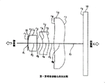
Fig. 1 and Figure 18 are respectively the structural drawing of the pick-up lens of first invention and second invention.Symbols such as surperficial sequence number that in Fig. 1 and Figure 18, defines and surface spacing, general in Fig. 2, Fig. 6, Figure 10, Figure 14, Figure 19, Figure 23, Figure 27 and Figure 31.
Begin to represent with L1, L2 and L3 respectively for first, second lens in turn from object side, represent aperture diaphragm with S1 and S2 with the 3rd.Represent to be arranged on the aperture diaphragm of the first lens L1 front side with S1, and represent to be arranged on aperture diaphragm between first lens and second lens with S2.
Under the situation of not misunderstanding, r
i(i=1,2,3 ..., 8) except going up the variable of radius-of-curvature, also can be used as the identification lens, the symbol of cover glass or shooting face (for example, r1 is used for representing the surface of the object side of first lens) as expression axle.
R shown in these figure
i(i=1,2,3 ..., 8) and d
i(i=1,2,3 ..., 7) isoparametric concrete numerical value provides by following table 1 to table 8.Subscript i, according to from object side to picture side order, at interval corresponding to the thickness of the surperficial sequence number of each lens, lens or lens surface.That is,
r
iThe axle that is the i surface is gone up radius-of-curvature,
d
iBe the distance on surface, i surface to the (i+1),
N
iBe refractive index by the material of lens of i surface and (i+1) surface formation
v
iBe Abbe number by the material of lens of i surface and (i+1) surface formation
Among Fig. 1 and Figure 18, the peristome of diaphragm is represented with line segment.Because, must conclusively show the intersection point of diaphragm face and optical axis in order to define distance from the camera lens face to the diaphragm face.Fig. 2, Fig. 6, Figure 10, Figure 14, Figure 19, Figure 23, Figure 27 and Figure 31 are respectively the sectional views of pinch picture camera lens of first embodiment to the, eight embodiment, opposite with above-mentioned Fig. 1 and Figure 18, the peristome of diaphragm opens wide, and is initial point interdicts light with two straight lines representatives diaphragm itself with the two ends of peristome.This is because in order to represent light such as chief ray, be necessary to reflect the virtual condition of diaphragm, represents so the peristome of diaphragm opened wide.
The long L of optics in pinch picture camera lens of first invention, is the distance from diaphragm S1 to the shooting face, in pinch picture camera lens of second invention, is the distance from the intersection point of the object side surface of first lens and optical axis to the face of shooting.Back focal length bf, be illustrated on the optical axis from the 3rd lens L3 the picture side to the shooting face distance.
To each hurdle of table 8, represent aspherical surface data at table 1 with surperficial sequence number.Because the surface of diaphragm S1, diaphragm S2 and shooting face all are the planes, its radius-of-curvature is represented with ∞.
The aspheric surface of using among the present invention is provided by following formula.
Z=ch
2/[1+[1-(1+k)c
2h
2]
+1/2]+A
0h
4+B
0h
6+C
0h
8+D
0h
10
In the formula,
Z: apart from the distance in the section of surface vertices
C: the paraxial curvature of face
H: apart from the height of optical axis
K: the constant of the cone
A
0: 4 grades of asphericity coefficients
B
0: 6 grades of asphericity coefficients
C
0: 8 grades of asphericity coefficients
D
0: 10 grades of asphericity coefficients
The table 1 of this instructions is represented the numerical value of asphericity coefficient, for example " e-1 " representative " 10 with exponential form to table 8
-1".The focal distance f value representation, the combined focal length of the lens combination of forming by the 1st to the 3rd lens.
Below with reference to Fig. 1 to Figure 17 first to fourth embodiment is described respectively, the 5th to the 8th embodiment is described respectively with reference to Figure 18 to Figure 34.
Fig. 3, Fig. 7, Figure 11, Figure 15, Figure 20, Figure 24, Figure 28 and Figure 32 represent the aberration that distorts, according to corresponding distance (longitudinal axis) expression aberration amount (transverse axis) to optical axis, the longitudinal axis adopts percent to represent, wherein the ultimate range apart from optical axis is 100 in the image planes, and transverse axis adopts percent to represent the discontented capacity of tangent condition.Fig. 4, Fig. 8, Figure 12, Figure 16, Figure 21, Figure 25, Figure 29 and Figure 33 represent astigmatism, the astigmatism curve is identical with the distortion aberration curve, corresponding to the distance shown in the longitudinal axis to optical axis, transverse axis is represented its aberration amount (mm unit), has represented the aberration amount (mm unit) of meridian ellipse (meridional) and sagittal surface (sagittal) among the figure respectively.Fig. 5, Fig. 9, Figure 13, Figure 17, Figure 22, Figure 26, Figure 30 and Figure 34 represent aberration/spherical aberration, and in aberration/spherical aberration curve, the longitudinal axis is the high h of incident (a F numerical value), and corresponding aberration amount (mm unit) is represented with transverse axis.
In addition, in aberration/spherical aberration curve, show and understand, d line (light of wavelength 587.6nm), e line (light of wavelength 546.1nm), the aberration amount of F line (light of wavelength 486.1nm) and g line (light of wavelength 435.8nm) with respect to C line (light of wavelength 656.3nm).Refractive index is the refractive index with respect to d line (light of 587.6nm).
Below, gather the radius-of-curvature (mm unit) that provides the relevant lenticular unit among first to the 8th embodiment, lens surface spacing (mm unit), the refractive index of lens material, Abbe number, focal length, F numerical value and the asphericity coefficient of lens material by table 1 to table 8.In first to the 8th embodiment, distinctly represent the focal length of the first lens L1, the second lens L2 and the 3rd lens L3 with f1, f2 and f3.In all embodiment of first to the 8th embodiment, f1 get on the occasion of, and f2 and f3 get negative value.That is, the first lens L1 is the lens with positive refractive power, and the second lens L2 and the 3rd lens L3 are the lens with negative refractive power.And the combined focal length f of pick-up lens is with 1.00mm normalization.
In addition, radius-of-curvature r on the optical axis
i(i=1,2,3 ..., 8), when object side is convex surface, get on the occasion of, when being convex surface, get negative value as side.By the value symbol of the radius-of-curvature of the curved surface that constitutes camera lens as can be known, the first lens L1 is object side and the convex lens that all are convex surface as side; The second lens L2 is the meniscus shaped lens that is convex surface as side; The 3rd lens L3 is object side and the convex lens that all are convex surface as side.
The following describes the feature of each embodiment.Among first to the 8th embodiment, the first lens L1 and the 3rd lens L3 adopt cyclenes plastics ZEONEX E48R (ZEONEX is the registered trademark of Japanese zeon incorporated company, and E48R is a production code member) to be material.And second lens L2 employing fluorenes kind polyester or polycarbonate are material.
ZEONEX E48R is 1.5304 with respect to the refractive index of d line, and fluorenes kind polyester and polycarbonate are respectively 1.607 and 1.5830 with respect to the refractive index of d line.The Abbe number of ZEONEXE48R is 56.0, and the Abbe number of fluorenes kind polyester and polycarbonate is respectively 27.0 and 30.0.
And, the two sides of the two sides of the first lens L1, the second lens L2, and the two sides of the 3rd lens L3 is an aspheric surface.
[first invention]
The pick-up lens of first invention has aperture diaphragm S1, the first lens L1, the second lens L2 and the 3rd lens L3 as shown in Figure 1, according to from object side to the picture side, constitute by the order of aperture diaphragm S1, the first lens L1, the second lens L2 and the 3rd lens L3.Below gathered to the table 4 among first to fourth embodiment of pick-up lens of first invention at table 1, about the radius-of-curvature (mm unit) of lenticular unit, lens surface spacing (mm unit), the refractive index of lens material, Abbe number, focal length, F numerical value and the asphericity coefficient of lens material.To table 4, the space D on the optical axis of the second lens L2 to the, three lens L3 is corresponding to d at table 1
5
[first embodiment]
It is material that the first lens L1 and the 3rd lens L3 adopt ZEONEX E48R, and the second lens L2 adopts fluorenes kind polyester EP-4000 (EP-4000 is the production code member of gas chemistry incorporated company of Mitsubishi) to be material.
(A) the object side radius-of-curvature r2=0.356mm of the first lens L1
(B) the picture side radius-of-curvature r3=-17.782mm of the first lens L1
(C) the interval D (=d on the optical axis of the second lens L2 and the 3rd lens L3
5)=0.1000mm
(D) the long L=1.121mm of optics
(E) image height (the diagonal angle line length of active area) 2Y=2 * 0.64=1.28mm
(F) the focal distance f 1=0.66mm of the first lens L1
Therefore:
|r2/r3|=|0.356/-17.782|=0.020
D/f=0.1000/1.00=0.1000
L/(2Y)=1.121/1.28=0.876
f1/f=0.66/1.00=0.66
So the lens combination among first embodiment, conditionals (1-1) all below satisfying are to (1-4).
0.01<|r2/r3|<0.05 (1-1)
0.05<D/f≤0.1 (1-2)
0.6<L/(2Y)<0.9 (1-3)
0.5<f1/f<0.7 (1-4)
The conditional of first invention of hereinafter mentioning refers to four conditionals of above-mentioned (1-1) to (1-4).
Diaphragm S1 is as shown in table 1, is located at the intersection point place of the first lens L1 the 1st (face of object side) and optical axis.Because of the diaphragm face is the plane, by r1=∞ in the table 1, diaphragm S1 is arranged at the r1 place as can be known.In addition, F numerical value is 3.4.
Fig. 2 shows the sectional view of the pick-up lens of bright first embodiment.With respect to focal length 1.00mm, back focal length is 0.389mm, therefore can guarantee sufficient length.
Fig. 3 shows bright distortion aberration curve 20, Fig. 4 shows bright astigmatism curve (to the aberration curve 22 of meridian ellipse (meridional) with to the aberration curve 24 of sagittal surface (sagittal)), and Fig. 5 show light colour poor/the spherical aberration curve is (with respect to the aberration curve 26 of C line, aberration curve 28 with respect to the d line, with respect to the aberration curve 30 of e line, with respect to the aberration curve 32 of F line with respect to the aberration curve 34 of g line).
The longitudinal axis of the aberration curve of Fig. 3 and Fig. 4 is represented image height with the percent value to optical axis distance.Among Fig. 3 and Fig. 4,100% corresponding to 0.640mm.In addition, the longitudinal axis of the aberration curve of Fig. 5 is represented the high h of incident (F number), and maximum corresponding to 3.4, transverse axis is represented the size of aberration amount.
The distortion aberration is located at image height 60% (image height 0.384mm), and the absolute value of aberration amount reaches and is 0.2640% to the maximum.And image height is during less than 0.640mm, and the absolute value of its aberration amount is all less than 0.2640%.
Astigmatism is located at image height 100% (image height 0.640mm), the absolute value of the aberration amount of meridian ellipse (meridional) is reached be 0.0513mm to the maximum.And image height is during less than 0.640mm, and the absolute value of its aberration amount is all less than 0.0513mm.
Aberration/spherical aberration is 30% place at the high h of incident, reaches with respect to the absolute value of the aberration amount of the aberration curve 34 of g line to be 0.0114mm to the maximum, and the absolute value of aberration amount is in 0.0114mm.
[second embodiment]
It is material that the first lens L1 and the 3rd lens L3 adopt ZEONEX E48R, and it is material that the second lens L2 adopts polycarbonate.
(A) the object side radius-of-curvature r2=0.356mm of the first lens L1
(B) the picture side radius-of-curvature r3=-17.782mm of the first lens L1
(C) the interval D (=d on the optical axis of the second lens L2 and the 3rd lens L3
5)=0.1000mm
(D) the long L=1.119mm of optics
(E) image height (the diagonal angle line length of active area) 2Y=2 * 0.64=1.28mm
(F) the focal distance f 1=0.66mm of the first lens L1
Therefore:
|r2/r3|=|0.356/-17.782|=0.020
D/f=0.1000/1.00=0.1000
L/(2Y)=1.119/1.28=0.874
f1/f=0.66/1.00=0.66
So the lens combination among second embodiment, conditionals (1-1) all below satisfying are to (1-4).
0.01<|r2/r3|<0.05 (1-1)
0.05<D/f≤0.1 (1-2)
0.6<L/(2Y)<0.9 (1-3)
0.5<f1/f<0.7 (1-4)
The conditional of first invention of hereinafter mentioning refers to four conditionals of above-mentioned (1-1) to (1-4).
Diaphragm S1 is as shown in table 2, is located at the intersection point place of the first lens L1 the 1st (face of object side) and optical axis.Because of the diaphragm face is the plane, by r1=∞ in the table 2, diaphragm S1 is arranged at the r1 place as can be known.In addition, F numerical value is 3.4.
Fig. 6 shows the sectional view of the pick-up lens of bright second embodiment.With respect to focal length 1.00mm, back focal length is 0.386mm, therefore can guarantee sufficient length.
Fig. 7 shows bright distortion aberration curve 36, Fig. 8 shows bright astigmatism curve (to the aberration curve 38 of meridian ellipse (meridional) with to the aberration curve 40 of sagittal surface (sagittal)), and Fig. 9 show light colour poor/the spherical aberration curve is (with respect to the aberration curve 42 of C line, aberration curve 44 with respect to the d line, with respect to the aberration curve 46 of e line, with respect to the aberration curve 48 of F line with respect to the aberration curve 50 of g line).
The longitudinal axis of the aberration curve of Fig. 7 and Fig. 8 is represented image height with the percent value to optical axis distance.Among Fig. 7 and Fig. 8,100% corresponding to 0.640mm.In addition, the longitudinal axis of the aberration curve of Fig. 9 is represented the high h of incident (F number), and maximum corresponding to 3.4, transverse axis is represented the size of aberration amount.
The distortion aberration is located at image height 60% (image height 0.384mm), and the absolute value of aberration amount reaches and is 0.2203% to the maximum.And image height is during less than 0.640mm, and the absolute value of its aberration amount is all less than 0.2203%.
Astigmatism is located at image height 100% (image height 0.640mm), the absolute value of the aberration amount of meridian ellipse (meridional) is reached be 0.0234mm to the maximum.And image height is during less than 0.640mm, and the absolute value of its aberration amount is all less than 0.0234mm.
Aberration/spherical aberration is 30% place at the high h of incident, reaches with respect to the absolute value of the aberration amount of the aberration curve 50 of g line to be 0.0129mm to the maximum, and the absolute value of aberration amount is in 0.0129mm.
[the 3rd embodiment]
It is material that the first lens L1 and the 3rd lens L3 adopt ZEONEX E48R, and it is material that the second lens L2 adopts polycarbonate.
(A) the object side radius-of-curvature r2=0.356mm of the first lens L1
(B) the picture side radius-of-curvature r3=-8.887mm of the first lens L1
(C) the interval D (=d on the optical axis of the second lens L2 and the 3rd lens L3
5)=0.08mm
(D) the long L=1.092mm of optics
(E) image height (the diagonal angle line length of active area) 2Y=2 * 0.64=1.28mm
(F) the focal distance f 1=0.65mm of the first lens L1
Therefore:
|r2/r3|=|0.356/-8.887|=0.04
D/f=0.08/1.00=0.08
L/(2Y)=1.092/1.28=0.8531
f1/f=0.65/1.00=0.65
So the lens combination among the 3rd embodiment, conditionals (1-1) all below satisfying are to (1-4).
0.01<|r2/r3|<0.05 (1-1)
0.05<D/f≤0.1 (1-2)
0.6<L/(2Y)<0.9 (1-3)
0.5<f1/f<0.7 (1-4)
The conditional of first invention of hereinafter mentioning is meant four conditionals of above-mentioned (1-1) to (1-4).
Diaphragm S1 is as shown in table 3, is located at the intersection point place of the first lens L1 the 1st (face of object side) and optical axis.Because of the diaphragm face is the plane, by r1=∞ in the table 3, diaphragm S1 is arranged at the r1 place as can be known.In addition, F numerical value is 3.4.
Figure 10 shows the sectional view of the pick-up lens of bright the 3rd embodiment.With respect to focal length 1.00mm, back focal length is 0.381mm, therefore can guarantee sufficient length.
Figure 11 shows bright distortion aberration curve 52, Figure 12 shows bright astigmatism curve (to the aberration curve 54 of meridian ellipse (meridional) with to the aberration curve 56 of sagittal surface (sagittal)), and Figure 13 show light colour poor/the spherical aberration curve is (with respect to the aberration curve 58 of C line, aberration curve 60 with respect to the d line, with respect to the aberration curve 62 of e line, with respect to the aberration curve 64 of F line with respect to the aberration curve 66 of g line).
The longitudinal axis of the aberration curve of Figure 11 and Figure 12 is represented image height with the percent value to optical axis distance.Among Figure 11 and Figure 12,100% corresponding to 0.640mm.In addition, the longitudinal axis of the aberration curve of Figure 13 is represented the high h of incident (F number), and maximum corresponding to 3.4, transverse axis is represented the size of aberration amount.
The distortion aberration is located at image height 100% (image height 0.640mm), and the absolute value of aberration amount reaches and is 0.5710% to the maximum.And image height is during less than 0.640mm, and the absolute value of its aberration amount is all less than 0.5710%.
Astigmatism is located at image height 100% (image height 0.640mm), the absolute value of the aberration amount of meridian ellipse (meridional) is reached be 0.0115mm to the maximum.And image height is during less than 0.640mm, and the absolute value of its aberration amount is all less than 0.0115mm.
Aberration/spherical aberration is 30% place at the high h of incident, reaches with respect to the absolute value of the aberration amount of the aberration curve 66 of g line to be 0.0154mm to the maximum, and the absolute value of aberration amount is in 0.0154mm.
[the 4th embodiment]
It is material that the first lens L1 and the 3rd lens L3 adopt ZEONEX E48R, and it is material that the second lens L2 adopts polycarbonate.
(A) the object side radius-of-curvature r2=0.356mm of the first lens L1
(B) the picture side radius-of-curvature r3=-8.887mm of the first lens L1
(C) the interval D (=d on the optical axis of the second lens L2 and the 3rd lens L3
5)=0.0511mm
(D) the long L=1.1043mm of optics
(E) image height (the diagonal angle line length of active area) 2Y=2 * 0.64=1.28mm
(F) the focal distance f 1=0.65mm of the first lens L1
Therefore:
|r2/r3|=|0.356/-8.887|=0.04
D/f=0.0511/1.00=0.0511
L/(2Y)=1.104/1.28=0.8627
f1/f=0.65/1.00=0.65
So the lens combination among the 4th embodiment, conditionals (1-1) all below satisfying are to (1-4).
0.01<|r2/r3|<0.05 (1-1)
0.05<D/f≤0.1 (1-2)
0.6<L/(2Y)<0.9 (1-3)
0.5<f1/f<0.7 (1-4)
The conditional of first invention of hereinafter mentioning is meant four conditionals of above-mentioned (1-1) to (1-4).
Diaphragm S1 is as shown in table 4, is located at the intersection point place of the first lens L1 the 1st (face of object side) and optical axis.Because of the diaphragm face is the plane, by r1=∞ in the table 4, diaphragm S1 is arranged at the r1 place as can be known.In addition, F numerical value is 3.4.
Figure 14 shows the sectional view of the pick-up lens of bright the 4th embodiment.With respect to focal length 1.00mm, back focal length is 0.422mm, therefore can guarantee sufficient length.
Figure 15 shows bright distortion aberration curve 68, Figure 16 shows bright astigmatism curve (to the aberration curve 70 of meridian ellipse (meridional) with to the aberration curve 72 of sagittal surface (sagittal)), and Figure 17 show light colour poor/the spherical aberration curve is (with respect to the aberration curve 74 of C line, aberration curve 76 with respect to the d line, with respect to the aberration curve 78 of e line, with respect to the aberration curve 80 of F line with respect to the aberration curve 82 of g line).
The longitudinal axis of the aberration curve of Figure 15 and Figure 16 is represented image height with the percent value to optical axis distance.Among Figure 15 and Figure 16,100% corresponding to 0.639mm.In addition, the longitudinal axis of the aberration curve of Figure 17 is represented the high h of incident (F number), and maximum corresponding to 3.4, transverse axis is represented the size of aberration amount.
The distortion aberration is located at image height 100% (image height 0.639mm), and the absolute value of aberration amount reaches and is 0.5428% to the maximum.And image height is during less than 0.639mm, and the absolute value of its aberration amount is all less than 0.5428%.
Astigmatism is located at image height 80% (image height 0.512mm), the absolute value of the aberration amount of meridian ellipse (meridional) is reached be 0.0512mm to the maximum.And image height is during less than 0.639mm, and the absolute value of its aberration amount is all less than 0.0512mm.
Aberration/spherical aberration is 30% place at the high h of incident, reaches with respect to the absolute value of the aberration amount of the aberration curve 82 of g line to be 0.0153mm to the maximum, and the absolute value of aberration amount is in 0.0153mm.
[second invention]
The pick-up lens of second invention has the first lens L1, aperture diaphragm S2, the second lens L2 and the 3rd lens L3 as shown in figure 18, according to from object side to the picture side, constitute by the order of the first lens L1, aperture diaphragm S2, the second lens L2 and the 3rd lens L3.Below gathered the 5th to the 8th embodiment of the pick-up lens of second invention to the table 8 at table 5, about the radius-of-curvature (mm unit) of lenticular unit, lens surface spacing (mm unit), the refractive index of lens material, Abbe number, focal length, F numerical value and the asphericity coefficient of lens material.To table 8, the space D on the optical axis of the second lens L2 to the, three lens L3 is corresponding to d at table 5
5.
[the 5th embodiment]
It is material that the first lens L1 and the 3rd lens L3 adopt ZEONEX E48R, and the second lens L2 adopts fluorenes kind polyester EP-4000 (EP-4000 is the production code member of gas chemistry incorporated company of Mitsubishi) to be material.
(A) the object side radius-of-curvature r1=0.356mm of the first lens L1
(B) the picture side radius-of-curvature r2=-17.782mm of the first lens L1
(C) interval D=0.1000mm on the optical axis of the second lens L2 and the 3rd lens L3
(D) the long L=1.1208mm of optics
(E) image height (the diagonal angle line length of active area) 2Y=2 * 0.64=1.28mm
(F) the focal distance f 1=0.66mm of the first lens L1
Therefore:
|r1/r2|=|0.356/-17.782|=0.020
D/f=0.1000/1.00=0.1000
L/(2Y)=1.121/1.28=0.8756
f1/f=0.66/1.00=0.66
So the lens combination among the 5th embodiment, conditionals (2-1) all below satisfying are to (2-4).
0.01<|r1/r2|<0.05 (2-1)
0.05<D/f≤0.1 (2-2)
0.6<L/(2Y)<0.9 (2-3)
0.5<f1/f<0.7 (2-4)
The conditional of second invention of hereinafter mentioning is meant four conditionals of above-mentioned (2-1) to (2-4).
Diaphragm S2 is as shown in table 5, is located between the first lens L1 and the first lens L2.Because of the diaphragm face is the plane, by r3=∞ in the table 5, diaphragm S2 is arranged at the r3 place as can be known.In addition, F numerical value is 3.4.
Figure 19 shows the sectional view of the pick-up lens of bright the 5th embodiment.With respect to focal length 1.00mm, back focal length is 0.389mm, therefore can guarantee sufficient length.
Figure 20 shows bright distortion aberration curve 120, Figure 21 shows bright astigmatism curve (to the aberration curve 122 of meridian ellipse (meridional) with to the aberration curve 124 of sagittal surface (sagittal)), and Figure 22 show light colour poor/the spherical aberration curve is (with respect to the aberration curve 126 of C line, aberration curve 128 with respect to the d line, with respect to the aberration curve 130 of e line, with respect to the aberration curve 132 of F line with respect to the aberration curve 134 of g line).
The longitudinal axis of the aberration curve of Figure 20 and Figure 21 is represented image height with the percent value to optical axis distance.Among Figure 24 and Figure 25,100% corresponding to 0.640mm.In addition, the longitudinal axis of the aberration curve of Figure 22 is represented the high h of incident (F number), and maximum corresponding to 3.4, transverse axis is represented the size of aberration amount.
The distortion aberration is located at image height 60% (image height 0.384mm), and the absolute value of aberration amount reaches and is 0.3310% to the maximum.And image height is during less than 0.640mm, and the absolute value of its aberration amount is all less than 0.3310%.
Astigmatism is located at image height 100% (image height 0.640mm), the absolute value of the aberration amount of sagittal surface (sagittal) is reached be 0.0196mm to the maximum.And image height is during less than 0.640mm, and the absolute value of its aberration amount is all less than 0.0196mm.
Aberration/spherical aberration is 30% place at the high h of incident, reaches with respect to the absolute value of the aberration amount of the aberration curve 134 of g line to be 0.0114mm to the maximum, and the absolute value of aberration amount is in 0.0114mm.
[the 6th embodiment]
It is material that the first lens L1 and the 3rd lens L3 adopt ZEONEX E48R, and it is material that the second lens L2 adopts polycarbonate.
(A) the object side radius-of-curvature r1=0.3566mm of the first lens L1
(B) the picture side radius-of-curvature r2=-17.782mm of the first lens L1
(C) interval D=0.1000mm on the optical axis of the second lens L2 and the 3rd lens L3
(D) the long L=1.119mm of optics
(E) image height (the diagonal angle line length of active area) 2Y=2 * 0.64=1.28mm
(F) the focal distance f 1=0.66mm of the first lens L1
Therefore:
|r1/r2|=|0.356/-17.782|=0.020
D/f=0.1000/1.00=0.1000
L/(2Y)=1.119/1.28=0.874
f1/f=0.66/1.00=0.66
So the lens combination among the 6th embodiment, conditionals (2-1) all below satisfying are to (2-4).
0.01<|r1/r2|<0.05 (2-1)
0.05<D/f≤0.1 (2-2)
0.6<L/(2Y)<0.9 (2-3)
0.5<f1/f<0.7 (2-4)
The conditional of second invention of hereinafter mentioning is meant four conditionals of above-mentioned (2-1) to (2-4).
Diaphragm S2 is as shown in table 6, is located between the first lens L1 and the first lens L2.Because of the diaphragm face is the plane, by r3=∞ in the table 6, diaphragm S2 is arranged at the r3 place as can be known.In addition, F numerical value is 3.4.
Figure 23 shows the sectional view of the pick-up lens of bright the 6th embodiment.With respect to focal length 1.00mm, back focal length is 0.386mm, therefore can guarantee sufficient length.
Figure 24 shows bright distortion aberration curve 136, Figure 25 shows bright astigmatism curve (to the aberration curve 138 of meridian ellipse (meridional) with to the aberration curve 140 of sagittal surface (sagittal)), and Figure 26 show light colour poor/the spherical aberration curve is (with respect to the aberration curve 142 of C line, aberration curve 144 with respect to the d line, with respect to the aberration curve 146 of e line, with respect to the aberration curve 148 of F line with respect to the aberration curve 150 of g line).
The longitudinal axis of the aberration curve of Figure 24 and Figure 25 is represented image height with the percent value to optical axis distance.Among Figure 24 and Figure 25,100% corresponding to 0.640mm.In addition, the longitudinal axis of the aberration curve of Figure 26 is represented the high h of incident (F number), and maximum corresponding to 3.4, transverse axis is represented the size of aberration amount.
The distortion aberration is located at image height 60% (image height 0.384mm), and the absolute value of aberration amount reaches and is 0.2936% to the maximum.And image height is during less than 0.640mm, and the absolute value of its aberration amount is all less than 0.2936%.
Astigmatism is located at image height 100% (image height 0.640mm), the absolute value of the aberration amount of sagittal surface (sagittal) is reached be 0.0221mm to the maximum.And image height is during less than 0.640mm, and the absolute value of its aberration amount is all less than 0.0221mm.
Aberration/spherical aberration is 30% place at the high h of incident, reaches with respect to the absolute value of the aberration amount of the aberration curve 150 of g line to be 0.0129mm to the maximum, and the absolute value of aberration amount is in 0.0129mm.
[the 7th embodiment]
It is material that the first lens L1 and the 3rd lens L3 adopt ZEONEX E48R, and it is material that the second lens L2 adopts polycarbonate.
(A) the object side radius-of-curvature r1=0.356mm of the first lens L1
(B) the picture side radius-of-curvature r2=-8.887mm of the first lens L1
(C) interval D=0.08mm on the optical axis of the second lens L2 and the 3rd lens L3
(D) the long L=1.092mm of optics
(E) image height (the diagonal angle line length of active area) 2Y=2 * 0.64=1.28mm
(F) the focal distance f 1=0.65mm of the first lens L1
Therefore:
|r1/r2|=|0.356/-8.887|=0.04
D/f=0.08/1.00=0.08
L/(2Y)=1.092/1.28=0.8531
f1/f=0.65/1.00=0.65
So the lens combination among the 7th embodiment, conditionals (2-1) all below satisfying are to (2-4).
0.01<|r1/r2|<0.05 (2-1)
0.05<D/f≤0.1 (2-2)
0.6<L/(2Y)<0.9 (2-3)
0.5<f1/f<0.7 (2-4)
The conditional of second invention of hereinafter mentioning is meant four conditionals of above-mentioned (2-1) to (2-4).
Diaphragm S2 is as shown in table 7, is located between the first lens L1 and the first lens L2.Because of the diaphragm face is the plane, by r3=∞ in the table 7, diaphragm S2 is arranged at the r3 place as can be known.In addition, F numerical value is 3.4.
Figure 27 shows the sectional view of the pick-up lens of bright the 7th embodiment.With respect to focal length 1.00mm, back focal length is 0.381mm, therefore can guarantee sufficient length.
Figure 28 shows bright distortion aberration curve 152, Figure 29 shows bright astigmatism curve (to the aberration curve 154 of meridian ellipse (meridional) with to the aberration curve 156 of sagittal surface (sagittal)), and Figure 30 show light colour poor/the spherical aberration curve is (with respect to the aberration curve 158 of C line, aberration curve 160 with respect to the d line, with respect to the aberration curve 162 of e line, with respect to the aberration curve 164 of F line with respect to the aberration curve 166 of g line).
The longitudinal axis of the aberration curve of Figure 28 and Figure 29 is represented image height with the percent value to optical axis distance.Among Figure 28 and Figure 29,100% corresponding to 0.640mm.In addition, the longitudinal axis of the aberration curve of Figure 30 is represented the high h of incident (F number), and maximum corresponding to 3.4, transverse axis is represented the size of aberration amount.
The distortion aberration is located at image height 80% (image height 0.512mm), and the absolute value of aberration amount reaches and is 0.3963% to the maximum.And image height is during less than 0.640mm, and the absolute value of its aberration amount is all less than 0.3963%.
Astigmatism is located at image height 100% (image height 0.640mm), the absolute value of the aberration amount of meridian ellipse (meridional) is reached be 0.0579mm to the maximum.And image height is during less than 0.640mm, and the absolute value of its aberration amount is all less than 0.0579mm.
Aberration/spherical aberration is 30% place at the high h of incident, reaches with respect to the absolute value of the aberration amount of the aberration curve 166 of g line to be 0.0154mm to the maximum, and the absolute value of aberration amount is in 0.0154mm.
[the 8th embodiment]
It is material that the first lens L1 and the 3rd lens L3 adopt ZEONEX E48R, and it is material that the second lens L2 adopts polycarbonate.
(A) the object side radius-of-curvature r1=0.356mm of the first lens L1
(B) the picture side radius-of-curvature r2=-8.887mm of the first lens L1
(C) interval D=0.0511mm on the optical axis of the second lens L2 and the 3rd lens L3
(D) the long L=1.104mm of optics
(E) image height (the diagonal angle line length of active area) 2Y=2 * 0.64=1.28mm
(F) the focal distance f 1=0.65mm of the first lens L1
Therefore:
|r1/r2|=|0.356/-8.887|=0.04
D/f=0.0511/1.00=0.0511
L/(2Y)=1.104/1.28=0.8627
f1/f=0.65/1.00=0.65
So the lens combination among the 8th embodiment, conditionals (2-1) all below satisfying are to (2-4).
0.01<|r1/r2|<0.05 (2-1)
0.05<D/f≤0.1 (2-2)
0.6<L/(2Y)<0.9 (2-3)
0.5<f1/f<0.7 (2-4)
The conditional of second invention of hereinafter mentioning is meant four conditionals of above-mentioned (2-1) to (2-4).
Diaphragm S2 is as shown in table 8, is located between the first lens L1 and the first lens L2.Because of the diaphragm face is the plane, by r3=∞ in the table 8, diaphragm S2 is arranged at the r3 place as can be known.In addition, F numerical value is 3.4.
Figure 31 shows the sectional view of the pick-up lens of bright the 8th embodiment.With respect to focal length 1.00mm, back focal length is 0.422mm, therefore can guarantee sufficient length.
Figure 32 shows bright distortion aberration curve 168, Figure 33 shows bright astigmatism curve (to the aberration curve 170 of meridian ellipse (meridional) with to the aberration curve 172 of sagittal surface (sagittal)), and Figure 34 show light colour poor/the spherical aberration curve is (with respect to the aberration curve 174 of C line, aberration curve 176 with respect to the d line, with respect to the aberration curve 178 of e line, with respect to the aberration curve 180 of F line with respect to the aberration curve 182 of g line).
The longitudinal axis of the aberration curve of Figure 32 and Figure 33 is represented image height with the percent value to optical axis distance.Among Figure 32 and Figure 33,100% corresponding to 0.640mm.In addition, the longitudinal axis of the aberration curve of Figure 34 is represented the high h of incident (F number), and maximum corresponding to 3.4, transverse axis is represented the size of aberration amount.
The distortion aberration is located at image height 100% (image height 0.640mm), and the absolute value of aberration amount reaches and is 0.3489% to the maximum.And image height is during less than 0.640mm, and the absolute value of its aberration amount is all less than 0.3489%.
Astigmatism is located at image height 100% (image height 0.640mm), the absolute value of the aberration amount of meridian ellipse (meridional) is reached be 0.0344mm to the maximum.And image height is during less than 0.640mm, and the absolute value of its aberration amount is all less than 0.0344mm.
Aberration/spherical aberration is 30% place at the high h of incident, reaches with respect to the absolute value of the aberration amount of the aberration curve 182 of g line to be 0.0154mm to the maximum, and the absolute value of aberration amount is in 0.0154mm.
From the explanation of the pick-up lens of first invention and second invention as can be known, as long as each lens design that constitutes pick-up lens is become the formula of satisfying condition (1-1) to (1-4) and conditional (2-1) to (2-4), just can solve problem of the present invention.That is, can obtain, not only various aberrations can be proofreaied and correct well, and can guarantee sufficient back focus and the long pick-up lens of short optics.
In the above embodiments, the first lens L1 and the 3rd lens L3 adopt the cyclenes plastic material, the second lens L2 adopts fluorenes kind polyester or polycarbonate plastic material, yet the plastic material beyond the embodiment, it even not plastic material, molded glass etc. for example, so long as satisfied the material of the various conditions that illustrate among the embodiment, no matter be that glass material or other materials can utilize.