CN100414970C - Image pickup apparatus having a display panel - Google Patents
Image pickup apparatus having a display panel Download PDFInfo
- Publication number
- CN100414970C CN100414970C CNB2005100779721A CN200510077972A CN100414970C CN 100414970 C CN100414970 C CN 100414970C CN B2005100779721 A CNB2005100779721 A CN B2005100779721A CN 200510077972 A CN200510077972 A CN 200510077972A CN 100414970 C CN100414970 C CN 100414970C
- Authority
- CN
- China
- Prior art keywords
- image
- operation unit
- image pick
- operating unit
- panel display
- Prior art date
- Legal status (The legal status is an assumption and is not a legal conclusion. Google has not performed a legal analysis and makes no representation as to the accuracy of the status listed.)
- Expired - Fee Related
Links
- 238000000034 method Methods 0.000 claims description 22
- 238000001514 detection method Methods 0.000 description 4
- RUZYUOTYCVRMRZ-UHFFFAOYSA-N doxazosin Chemical compound C1OC2=CC=CC=C2OC1C(=O)N(CC1)CCN1C1=NC(N)=C(C=C(C(OC)=C2)OC)C2=N1 RUZYUOTYCVRMRZ-UHFFFAOYSA-N 0.000 description 2
- 230000003287 optical effect Effects 0.000 description 2
- 230000000007 visual effect Effects 0.000 description 2
- 210000003811 finger Anatomy 0.000 description 1
- 210000005224 forefinger Anatomy 0.000 description 1
- 239000004973 liquid crystal related substance Substances 0.000 description 1
- 239000004065 semiconductor Substances 0.000 description 1
- 230000005236 sound signal Effects 0.000 description 1
- 210000003813 thumb Anatomy 0.000 description 1
Images


Classifications
-
- H—ELECTRICITY
- H04—ELECTRIC COMMUNICATION TECHNIQUE
- H04N—PICTORIAL COMMUNICATION, e.g. TELEVISION
- H04N23/00—Cameras or camera modules comprising electronic image sensors; Control thereof
- H04N23/50—Constructional details
- H04N23/53—Constructional details of electronic viewfinders, e.g. rotatable or detachable
- H04N23/531—Constructional details of electronic viewfinders, e.g. rotatable or detachable being rotatable or detachable
-
- H—ELECTRICITY
- H04—ELECTRIC COMMUNICATION TECHNIQUE
- H04N—PICTORIAL COMMUNICATION, e.g. TELEVISION
- H04N23/00—Cameras or camera modules comprising electronic image sensors; Control thereof
- H04N23/60—Control of cameras or camera modules
- H04N23/63—Control of cameras or camera modules by using electronic viewfinders
Landscapes
- Engineering & Computer Science (AREA)
- Multimedia (AREA)
- Signal Processing (AREA)
- Studio Devices (AREA)
- Structure And Mechanism Of Cameras (AREA)
- Camera Bodies And Camera Details Or Accessories (AREA)
Abstract
An image pick up apparatus having a freely openable and closable panel display that includes a first operation unit provided on a body side of the image pick up apparatus and a second operation unit provided at the panel display, wherein the first operation unit and the second operation unit have an equivalent operation function.
Description
The cross reference of related application
The present invention comprises and relates to the theme of June 16 in 2004 at the Japanese patent application JP2004-178757 of Japan Patent office submission, by reference its full content is herein incorporated.
Technical field
The present invention relates to a kind of image pick-up device.More specifically, the present invention relates to a kind of image pick-up device with the panel display that can freely open and close, wherein, fuselage side at image pick-up device has first operating unit, and on panel display, have second operating unit, by giving first operating unit and second operating unit has improved its operability with identical functions.
Background technology
In correlation technique, the image pick-up device that can easily enjoy the shooting of moving image capture and rest image has become general.Therefore such image pick-up device has zoom function, and can use this zoom function easily with the image of required size reference object.By utilizing the rotation of motor, zoom function makes the focal length of image pickup camera lens change to the scope of dolly-out,ing dolly-back continuously from wide and need not to change camera lens, keeps the optical relation stipulated simultaneously thereby move the multiple series of images pick-up lens along optical axis direction.For example, the camera with the zoom device with patent documentation (the open No.2652891 of Japan Patent) provides TW zoom operation unit and TW direct control unit.When operation TW zoom operation unit, then carry out zoom operation, and when operation TW direct control unit, then the image pickup camera lens directly might be moved to dolly-out, dolly-back end and wide-angle side.
In addition, when carrying out rest image with stillcamera etc. and take,, might automatically adjust camera parameter such as focal length and time for exposure etc. are set when the shutter operation unit half that is pressed.When the shutter operation unit was pressed fully, camera was provided with parameter and is fixed and can takes rest image.
Summary of the invention
Here, zoom operation unit of operating when using zoom function and the shutter operation unit of operating when taking rest image are provided at the position that makes it possible to by operations such as thumb that supports hand and forefingers, so that make it possible to direct control when supporting image pick-up device with a hand.But image pick-up device has various types of users, for example the people of the people of big hand or little hand.Therefore have zoom operation unit and shutter operation unit may be not in the situation of the position of direct control.In addition, under the situation of the design of holding image pick-up device with the right hand, the operation of zoom operation unit and shutter operation unit is just difficult for the people that dominant hand is left hand.
Therefore the invention provides a kind of image pick-up device that improves its operability.
Therefore, image pick-up device of the present invention is the image pick-up device with the panel display that can freely open and close, fuselage side at image pick-up device has first operating unit, and on panel display, having second operating unit, first operating unit and second operating unit have the operating function that is equal to.In addition, as the operating function that is equal to, be provided with the zoom operation function and the shutter operation function that are used to take rest image.
According to the present invention, have first operating unit in the fuselage side of image pick-up device, and on panel display, have second operating unit, first operating unit and second operating unit have the operating function that is equal to.In addition, as the operating function that is equal to, be provided with the zoom operation function and the shutter operation function that are used to take rest image.The result, for example can not use easily under the situation of right-hand operated first operating unit with right hand support image pick-up device, may be by carrying out zoom operation and shutter operation with left-handed operation second operating unit, thus the operability of image pick-up device improved.
Description of drawings
Fig. 1 is the view that the outward appearance of image pick-up device is shown;
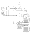
Fig. 2 is the view that the internal structure summary of image pick-up device is shown;
Fig. 3 is the flow chart that zoom operation is shown; And
Fig. 4 is the flow chart that the operation that is used to take rest image is shown.
Embodiment
Be the description that the accompanying drawing with reference to embodiments of the invention carries out below.Fig. 1 illustrates the outward appearance of image pick-up device 10, and wherein Figure 1A illustrates the situation of looking down image pick-up device 10 from the left back, and 1B illustrates the situation of looking down image pick-up device 10 from the right back.
The mains switch 121 of the operation that is used to start or finish image pick-up device 10 is provided on the rear surface of the fuselage of image pick-up device 10.In addition, at mains switch 121, might be at the moving image mode that is used to write down moving image, be used to write down the rest image pattern of rest image and be used to play the moving image that write down or the operator schemes such as play mode of rest image between switch.
Rear end in the right lateral surface of the fuselage of image pick-up device 10 provides the recording start/shutdown switch 122 that is used to start or stop the operation of moving image record.Fuselage side zoom operation unit 123 and the fuselage side shutter operation unit 124 when the front of the right lateral surface of the fuselage of image pick-up device 10 provides when the record rest image, operated.
Top at the fuselage of image pick-up device 10 provides electronic viewfinder (after this being called " EVF ") 31.Left-hand face at fuselage provides panel display 40 in the mode that can freely open and close.With flat-panel screens 41 as structural plane panel displays 40 such as liquid crystal display cells.In addition, the external frame on the opposite of support-side partly provides panel side zoom operation unit 423, and the downside in panel side zoom operation unit 423 provides panel side shutter operation unit 424.
When mains switch 121 is set to moving image mode, when pressing hypograph recording start/shutdown switch 122, image pick-up device 10 begins motion of objects image recording operation, and finishes the operation of moving image record when pressing hypograph recording start/shutdown switch 122 once more.The image of being caught is presented on EVF 31 and/or the panel display 40 then.For example, when having closed panel display 40, on EVF 31, show the image of being caught.In addition, when panel display 40 is opened as shown in Figure 1, on the flat-panel screens 41 of panel display 40, show the image of being caught.When panel display 40 is opened, also can on EVF 31, show the image of being caught.
When mains switch 121 is set to the rest image pattern and a half is pressed in the shutter operation unit 124 of fuselage side or the shutter operation unit 424 of panel side, adjust focal length and exposure etc. automatically.In the time of the shutter operation unit 424 of the shutter operation unit 124 of pressing the fuselage side fully or panel side, then be the object record rest image.
When carrying out the operation of specifying play mode, carry out the broadcast of moving image and rest image according to the play mode of appointment when mains switch 121 is set to play mode.For example, on the screen of flat-panel monitor 41, provide touch panel switch 425.When mains switch 121 was set to play mode, menu displayed the play on panel display 40.When the operation of a kind of play mode of appointment of carrying out from the menu that shows is indicated as operation signal from touch panel switch 425, carry out the broadcast of moving image and rest image by the play mode of appointment.
Showing on EVF 31 or the panel display 40 under the situation of captured image mains switch 121 being set to moving image mode or rest image pattern, if the wide angle switch WZ-P of operation fuselage side zoom operation unit 123 or panel side zoom operation unit 423, then drive the image pickup camera lens, to widen the visual angle of captured image.In addition, if the switch TZ-P that dolly-out,s dolly-back of operation fuselage side zoom operation unit 123 or panel side zoom operation unit 423, then mobile image pickup camera lens shows to amplify object.
Fig. 2 shows the summary of the internal structure of image pick-up device 10.Image pickup camera lens part 21 forms object images at the image pickup surface of image pickup part 22.Lens driver of describing later 27 and controller 28 drive image pickup camera lens part 21.Image pickup part 22 converts object images to electronic signal, and outputs to signal processor 23.Signal processor 23 is handled the signal of being supplied by image pickup part 22, and outputs to record/broadcast part 24.The picture signal record that record/broadcast part 24 provides signal processor 23 is to recording medium 25.The microphone (not shown) is collected sound, and will be input to record/broadcast part 24 by the audio signal that microphone obtains, and is recorded on the recording medium 25 by record/broadcast part 24 with picture signal.Tape, CD or semiconductor memory etc. can be used as recording medium 25.Moving image and rest image can record on identical recording medium or the different recording medium.
Record/broadcast part 24 picture signal that signal processor 23 is provided or offer output dip switch 26 then from the picture signal that recording medium 25 reads.Output dip switch 26 is supplied with the picture signal that record/broadcast part 24 provides the flat-panel screens 41 of EVF 31 or panel display 40.Based on the picture signal that provides via output dip switch 26, the flat-panel screens of EVF 31 or panel display 40 41 shows the image of just taking or is recorded in moving image and rest image on the recording medium.In addition, lens driver 27 drives image pickup camera lens part 21, thereby carries out the operation that changes enlargement ratio and do not change the image space of object.
Fuselage side operating unit 12 is made up of mains switch 121, image recording start/shutdown switch 122, fuselage side zoom operation unit 123 and fuselage side shutter operation unit 124, and produce operation signal according to each switching manipulation, and these operation signals are offered controller 28.In addition, panel side operating unit 42 is made up of panel side zoom operation unit 423, panel side shutter operation unit 424 and touch panel switch 425 etc., and produces operation signal according to each switching manipulation, and these operation signals are offered controller 28.Panel ON/OFF detector 13 detection faces panel displays 40 are opened or are closed, and produce the detection signal of indication testing result, and these results are supplied with controller 28.
With the isostructure controller 28 of microcomputer based on producing control signal CS from the operation signal of fuselage side operating unit 12 and panel side operating unit 42 and from the detection signal of panel ON/OFF detector 13.The control signal CS that produces is supplied with image pickup camera lens part 21, image pickup part 22, signal processor 23, record/broadcast part 24 and output dip switch 26, and come the mode of executable operations to control each operation with operation according to fuselage side operating unit 12 and panel side operating unit 42.In addition, when controller 28 when determining that from the detection signal of panel ON/OFF detector 13 panel display 40 is closed, it is invalid to be set to from the operation signal of panel side operating unit 42.By this way, invalid by when panel display 40 is closed, making from the operation signal of panel side operating unit 42, even touch other parts so that in the operation that leads to errors, also prevent to carry out zoom operation and shutter operation in panel side zoom operation unit 423 grades.
Fig. 3 is the flow chart that is illustrated in the zoom operation when might use fuselage side zoom operation unit 123 and panel side zoom operation unit 423 respectively.
At step ST1, controller 28 determines whether to connect the wide angle switch WZ-B of fuselage side zoom operation unit 123.When thereby operation wide angle switch WZ-B continued, process entered into step ST5, but when wide angle switch WZ-B access failure, process enters step ST2.
At step ST2, controller 28 determines whether to connect the switch TZ-B that dolly-out,s dolly-back of fuselage side zoom operation unit 123.When thereby switch TZ-B continuation was dolly-out,ed dolly-back in operation, process entered into step ST6, but when dolly-out,ing dolly-back switch TZ-B access failure, process enters step ST3.
At step ST3, controller 28 determines whether to connect the wide angle switch WZ-P of panel side zoom operation unit 423.When thereby operation wide angle switch WZ-P continued, process entered into step ST5, but when wide angle switch WZ-P access failure, process enters step ST4.
At step ST4, controller 28 determines whether to open the switch TZ-P that dolly-out,s dolly-back of panel side zoom operation unit 423.When thereby switch TZ-P continuation was dolly-out,ed dolly-back in operation, process entered into step ST6, but when wide angle switch TZ-P access failure, finishes zoom operation.
At step ST5, by driving image pickup camera lens part 21 does not change object to reduce multiplication factor image space with lens driver 27, controller 28 is carried out the operation of zoom wide-angles widening the visual angle of the image of just taking, and finishes zoom operation.At step ST6, by driving image pickup camera lens part 21 does not change object to increase multiplication factor image space with lens driver 27, the operation of dolly-out,ing dolly-back increases the object size of the image of just taking thereby controller 28 is carried out zooms, and finishes zoom operation.
Next, use the flow chart of Fig. 4 to provide the description of the rest image pick-up operation to might use fuselage side shutter operation unit 124 and panel side shutter operation unit 424 respectively the time.
At step ST11, controller 28 determines whether to supress fully fuselage side shutter operation unit 124.When supressing fuselage side shutter operation unit 124 fully, process enters into step ST 15, and when not pressing fuselage side shutter operation unit 124 fully, process enters into step ST12.
At step ST13, controller 28 determines whether to supress fully panel side shutter operation unit 424.When supressing panel side shutter operation unit 424 fully, process enters into step ST15, and when not pressing lower panel side shutter operation unit 424 fully, process enters into step ST13.
At step ST13, controller 28 determines whether fuselage side shutter operation unit 124 is pressed half.When fuselage side shutter operation unit 124 half that is pressed, process enters into step ST16, and when fuselage side shutter operation unit 124 half that is not pressed, process enters into step ST14.
At step ST14, controller 28 determines whether panel side shutter operation unit 424 is pressed half.When panel side shutter operation unit 424 half that is pressed, process enters into step ST16, and when panel side shutter operation unit 424 half that is not pressed, this process finishes.
When process when step ST11 or step ST12 enter into step ST15, controller 28 is only to come controlling recording/broadcast part 24 with an image displayed record of picture signal to the mode on the recording medium 25 when pressing fuselage side shutter operation unit 124 or panel side shutter operation unit 424 fully, this process finishes then.In addition, when process when step ST13 or step ST14 enter into step ST16, controller 28 with in fuselage side shutter operation unit 124 or panel side shutter operation unit 424 mode that a half automatically adjusts focal length and exposure etc. that is pressed come control chart as pick-up lens part 21 and lens driver 27 etc., this process finishes then.
In the zoom operation of the foregoing description, image pickup camera lens part 21 is driven by lens driver 27, but for example can handle picture signal makes object be exaggerated demonstration, promptly so-called electronic zoom.
In this case, not only all provide zoom operation unit and shutter operation unit in fuselage but also in the side of panel display unit.This means and for example can not easily operate under the situation of fuselage side zoom operation unit 123 or the wide angle switch WZ-B of fuselage side shutter operation unit 124 or the switch TZ-B that dolly-out,s dolly-back, might be provided at the wide angle switch WZ-P of the panel side zoom operation unit 423 on the panel display 40 or the switch TZ-P or of dolly-out,ing dolly-back by operation by using another manual manipulation panel side shutter operation unit 424 to carry out zoom operation and write down rest image in direct mode with the finger of the hand of holding image pick-up device 10.
As mentioned above, image pick-up device of the present invention can be in order to improve the operability during zoom operation and to take rest image.
It should be appreciated by those skilled in the art, only otherwise break away from, can carry out various adjustment, combination, part combination and change according to design needs and other factors by appended claims or its equivalent institute restricted portion.
Claims (5)
1. an image pick-up device (10) has the panel display (40) that can freely open and close, and this image pick-up device comprises:
Be provided at first operating unit (12) of the fuselage side of image pick-up device; With
Be provided at second operating unit (42) on the external frame part on opposite of support-side of panel display;
Wherein first operating unit (12) and second operating unit (42) have the operating function that is equal to, and when panel display (40) when being closed, it is invalid to make from the operation signal of second operating unit (42).
2. image pick-up device as claimed in claim 1,
Wherein, the operating function that is equal to is the zoom operation function.
3. image pick-up device as claimed in claim 1,
Wherein, the operating function that is equal to is the shutter operation function when taking rest image.
4. the described image pick-up device of arbitrary as described above claim, wherein, when described panel display was opened, first operating unit and second operating unit all can be operated.
5. image pickup method, its use has the image pick-up device of the panel display that can freely open and close,
Wherein, operate this image pick-up device with second operating unit on the external frame part on first operating unit that is provided at image pick-up device fuselage side and the opposite of the support-side that is provided at panel display, described first operating unit and described second operating unit all have the operating function that is equal to, and when panel display was closed, it was invalid to make from the operation signal of second operating unit.
Applications Claiming Priority (2)
| Application Number | Priority Date | Filing Date | Title |
|---|---|---|---|
| JP178757/04 | 2004-06-16 | ||
| JP2004178757A JP2006005579A (en) | 2004-06-16 | 2004-06-16 | Imaging device |
Related Child Applications (1)
| Application Number | Title | Priority Date | Filing Date |
|---|---|---|---|
| CN2008101087810A Division CN101291395B (en) | 2004-06-16 | 2005-06-16 | Image pickup apparatus having a display panel |
Publications (2)
| Publication Number | Publication Date |
|---|---|
| CN1713695A CN1713695A (en) | 2005-12-28 |
| CN100414970C true CN100414970C (en) | 2008-08-27 |
Family
ID=35124525
Family Applications (2)
| Application Number | Title | Priority Date | Filing Date |
|---|---|---|---|
| CNB2005100779721A Expired - Fee Related CN100414970C (en) | 2004-06-16 | 2005-06-16 | Image pickup apparatus having a display panel |
| CN2008101087810A Expired - Fee Related CN101291395B (en) | 2004-06-16 | 2005-06-16 | Image pickup apparatus having a display panel |
Family Applications After (1)
| Application Number | Title | Priority Date | Filing Date |
|---|---|---|---|
| CN2008101087810A Expired - Fee Related CN101291395B (en) | 2004-06-16 | 2005-06-16 | Image pickup apparatus having a display panel |
Country Status (5)
| Country | Link |
|---|---|
| US (1) | US20050285964A1 (en) |
| EP (1) | EP1608155A3 (en) |
| JP (1) | JP2006005579A (en) |
| KR (1) | KR20060049594A (en) |
| CN (2) | CN100414970C (en) |
Families Citing this family (2)
| Publication number | Priority date | Publication date | Assignee | Title |
|---|---|---|---|---|
| KR20080061844A (en) * | 2006-12-28 | 2008-07-03 | 삼성전자주식회사 | Image photography apparatus |
| KR101371414B1 (en) | 2007-01-31 | 2014-03-10 | 삼성전자주식회사 | Combination A/V apparatus with multi function and method for providing UI |
Citations (4)
| Publication number | Priority date | Publication date | Assignee | Title |
|---|---|---|---|---|
| US5729289A (en) * | 1994-11-08 | 1998-03-17 | Canon Kabushiki Kaisha | Image pick-up device and detachable display device each including means for controlling a predetermined function |
| EP1158785A2 (en) * | 2000-05-18 | 2001-11-28 | Sony Corporation | An image pickup apparatus and its operation method |
| US20020130962A1 (en) * | 2001-03-19 | 2002-09-19 | Tamotsu Senda | Electronic camera recording/playback apparatus |
| US20030163623A1 (en) * | 2002-02-22 | 2003-08-28 | Yeung Chi Ping | Image capture device |
Family Cites Families (26)
| Publication number | Priority date | Publication date | Assignee | Title |
|---|---|---|---|---|
| JP2652891B2 (en) | 1989-10-04 | 1997-09-10 | 富士写真光機株式会社 | Camera with zoom device |
| JP3496207B2 (en) * | 1994-06-22 | 2004-02-09 | ソニー株式会社 | Video camera |
| KR0113218Y1 (en) * | 1994-11-25 | 1998-04-13 | 이헌조 | Handgrip unified l.c.d. for camcordr |
| JPH1031254A (en) * | 1996-07-15 | 1998-02-03 | Nikon Corp | Camera and camera accessory |
| JP3546784B2 (en) * | 1999-12-14 | 2004-07-28 | 日本電気株式会社 | Mobile device |
| US7046287B2 (en) * | 1999-12-24 | 2006-05-16 | Nec Corporation | Portable information terminal equipped with camera |
| JP3546996B2 (en) * | 1999-12-24 | 2004-07-28 | 日本電気株式会社 | Personal digital assistant with camera |
| JP4210818B2 (en) * | 2000-07-31 | 2009-01-21 | 富士フイルム株式会社 | camera |
| JP3636057B2 (en) * | 2000-10-13 | 2005-04-06 | ソニー株式会社 | Portable information processing apparatus, information processing method in portable information processing apparatus, and program storage medium in portable information processing apparatus |
| JP3859196B2 (en) * | 2001-01-31 | 2006-12-20 | 富士フイルムホールディングス株式会社 | Digital camera |
| JP4944306B2 (en) * | 2001-04-16 | 2012-05-30 | キヤノン株式会社 | Recording device |
| KR100412485B1 (en) * | 2001-06-22 | 2003-12-31 | 삼성전자주식회사 | Automatically ejectable Viewfinder of photographing apparatus and phtographing apparatus therewith |
| JP3910112B2 (en) * | 2002-06-21 | 2007-04-25 | シャープ株式会社 | Camera phone |
| JP4071568B2 (en) * | 2002-07-30 | 2008-04-02 | シャープ株式会社 | Portable device |
| JP2004078011A (en) * | 2002-08-21 | 2004-03-11 | Fuji Photo Film Co Ltd | Digital camera |
| JP4030862B2 (en) | 2002-11-29 | 2008-01-09 | 株式会社リコー | Multilevel recording wobble signal detection method and optical information recording apparatus |
| CN1507268A (en) * | 2002-12-09 | 2004-06-23 | �ʼҷ����ֵ��ӹɷ�����˾ | Digital camera with dismountable display screen as remote-controller |
| US20040208492A1 (en) * | 2003-01-06 | 2004-10-21 | Samsung Electronic Co., Ltd. | Video/audio data recording/reproducing apparatus |
| JP3829937B2 (en) * | 2003-07-16 | 2006-10-04 | ソニー株式会社 | Imaging apparatus and imaging system control method |
| JP4380475B2 (en) * | 2003-10-02 | 2009-12-09 | ソニー株式会社 | Imaging device |
| JP2004159363A (en) * | 2003-12-26 | 2004-06-03 | Sharp Corp | Mobile phone |
| JP4101744B2 (en) * | 2003-12-26 | 2008-06-18 | シャープ株式会社 | Mobile terminal device |
| JP2005192011A (en) * | 2003-12-26 | 2005-07-14 | Sony Corp | Camera |
| JP2005189601A (en) * | 2003-12-26 | 2005-07-14 | Sony Corp | Camera |
| KR100867434B1 (en) * | 2006-07-24 | 2008-11-06 | 닛뽕빅터 가부시키가이샤 | Hinge unit and image display device |
| JP4697256B2 (en) * | 2008-04-16 | 2011-06-08 | ソニー株式会社 | Display device |
-
2004
- 2004-06-16 JP JP2004178757A patent/JP2006005579A/en active Pending
-
2005
- 2005-06-14 EP EP05253686A patent/EP1608155A3/en not_active Ceased
- 2005-06-15 KR KR1020050051181A patent/KR20060049594A/en not_active Application Discontinuation
- 2005-06-15 US US11/152,068 patent/US20050285964A1/en not_active Abandoned
- 2005-06-16 CN CNB2005100779721A patent/CN100414970C/en not_active Expired - Fee Related
- 2005-06-16 CN CN2008101087810A patent/CN101291395B/en not_active Expired - Fee Related
Patent Citations (4)
| Publication number | Priority date | Publication date | Assignee | Title |
|---|---|---|---|---|
| US5729289A (en) * | 1994-11-08 | 1998-03-17 | Canon Kabushiki Kaisha | Image pick-up device and detachable display device each including means for controlling a predetermined function |
| EP1158785A2 (en) * | 2000-05-18 | 2001-11-28 | Sony Corporation | An image pickup apparatus and its operation method |
| US20020130962A1 (en) * | 2001-03-19 | 2002-09-19 | Tamotsu Senda | Electronic camera recording/playback apparatus |
| US20030163623A1 (en) * | 2002-02-22 | 2003-08-28 | Yeung Chi Ping | Image capture device |
Also Published As
| Publication number | Publication date |
|---|---|
| US20050285964A1 (en) | 2005-12-29 |
| EP1608155A2 (en) | 2005-12-21 |
| EP1608155A3 (en) | 2006-06-21 |
| CN101291395A (en) | 2008-10-22 |
| CN101291395B (en) | 2012-07-18 |
| JP2006005579A (en) | 2006-01-05 |
| KR20060049594A (en) | 2006-05-19 |
| CN1713695A (en) | 2005-12-28 |
Similar Documents
| Publication | Publication Date | Title |
|---|---|---|
| US7046286B1 (en) | Video camera | |
| JP2001326843A (en) | Image pickup device and its operation method | |
| KR20060099869A (en) | Digital photographing apparatus having two display panels and controlling method therefor | |
| JP2000101879A (en) | Image pickup device | |
| JP4857097B2 (en) | Operation device and control method thereof | |
| US6912005B2 (en) | Electronic camera recording/playback apparatus for shooting pictures and editing shot data | |
| CN100414970C (en) | Image pickup apparatus having a display panel | |
| JP2007028229A (en) | Photographing device | |
| JP2006319903A (en) | Mobile apparatus provided with information display screen | |
| JP2000165718A (en) | Electronic image pickup device | |
| JP2009089328A (en) | Digital camera | |
| TWI231429B (en) | Imaging apparatus, method of creating album files, and a storage medium that records method of creating album files | |
| JP2007048123A (en) | Display device | |
| US20060215051A1 (en) | Display device | |
| JP2952182B2 (en) | Imaging device | |
| US7982780B2 (en) | Photographing apparatus having multiple control button sets and displays and method of displaying image | |
| JP4537107B2 (en) | Video display device, video display method, and computer program | |
| KR20080057048A (en) | Method of controlling digital photographing apparatus within night photographing mode | |
| JP2005197965A (en) | Digital camera | |
| JP4256037B2 (en) | Electronic camera recording and playback device | |
| JP2904736B2 (en) | Video camera with integrated still camera | |
| JP4564865B2 (en) | Imaging apparatus and method, and program | |
| JPH09163214A (en) | Camera incorpolated recording and reproducing device and its function setting method | |
| JP2000235226A (en) | Camera device for drawings and calligraphy | |
| JP2007096682A (en) | Digital camera |
Legal Events
| Date | Code | Title | Description |
|---|---|---|---|
| C06 | Publication | ||
| PB01 | Publication | ||
| C10 | Entry into substantive examination | ||
| SE01 | Entry into force of request for substantive examination | ||
| C14 | Grant of patent or utility model | ||
| GR01 | Patent grant | ||
| CF01 | Termination of patent right due to non-payment of annual fee |
Granted publication date: 20080827 Termination date: 20150616 |
|
| EXPY | Termination of patent right or utility model |