CN100405015C - A Fiber Optic Gyro Inertial Measurement System with High Vibration Resistance - Google Patents
A Fiber Optic Gyro Inertial Measurement System with High Vibration Resistance Download PDFInfo
- Publication number
- CN100405015C CN100405015C CNB2005100748564A CN200510074856A CN100405015C CN 100405015 C CN100405015 C CN 100405015C CN B2005100748564 A CNB2005100748564 A CN B2005100748564A CN 200510074856 A CN200510074856 A CN 200510074856A CN 100405015 C CN100405015 C CN 100405015C
- Authority
- CN
- China
- Prior art keywords
- fiber optic
- optic gyroscope
- pendulum
- measurement system
- inertial measurement
- Prior art date
- Legal status (The legal status is an assumption and is not a legal conclusion. Google has not performed a legal analysis and makes no representation as to the accuracy of the status listed.)
- Expired - Lifetime
Links
Images


Landscapes
- Gyroscopes (AREA)
Abstract
一种具有高抗振性能的光纤陀螺惯性测量系统,主要包括三只光纤陀螺、三只石英加速度计、本体结构等,其特点在于:(1)所述的光纤陀螺采用全固态数字闭环光纤陀螺;(2)所述的加速度计采用抗冲击石英加速度计;(3)所述的本体采用薄壁加筋金属合金结构。本发明在对外连接无需任何减振的情况下,能够承受恶劣的冲击、振动等力学环境条件并保持较好精度,同时也使惯性测量系统保持了安装精度的长期稳定性,提高了惯性测量系统的综合性能。
A fiber optic gyroscope inertial measurement system with high anti-vibration performance mainly includes three fiber optic gyroscopes, three quartz accelerometers, a body structure, etc., and is characterized in that: (1) the fiber optic gyroscope adopts an all-solid-state digital closed-loop fiber optic gyroscope; 2) The accelerometer adopts an anti-shock quartz accelerometer; (3) The body adopts a thin-walled reinforced metal alloy structure. The present invention can withstand severe impact, vibration and other mechanical environment conditions without any vibration reduction for external connection, and maintain good accuracy, and at the same time, it also enables the inertial measurement system to maintain long-term stability of installation accuracy, and improves the inertial measurement system. comprehensive performance.
Description
所属技术领域Technical field
本发明涉及一种光纤陀螺惯性测量系统,特别是一种具有高抗振性能的光纤陀螺惯性测量系统。The invention relates to a fiber optic gyro inertial measurement system, in particular to a fiber optic gyro inertial measurement system with high anti-vibration performance.
背景技术 Background technique
惯性测量系统是实现导弹、运载火箭等飞行器制导与稳定控制的关键敏感测量设备和基准信息源,能够在飞行过程中为飞行器建立基准坐标系,敏感其运动的角速度、视加速度,准确测量姿态、位置、速度等,并通过接口高速输出数据,同时为惯性制导和姿态控制系统提供测量信息,以实现稳定飞行,准确命中目标。新型战术武器不仅要求快速反应、机动突防、精确打击能力,还要求小型化、多功能,在恶劣的环境条件下保持高可靠性、适应强烈的振动、冲击和大过载,同时要求性能保持长期稳定和高寿命,能够在长期贮存条件下始终保持性能稳定,这对其中的惯性测量系统提出了很高的要求。The inertial measurement system is the key sensitive measurement equipment and reference information source to realize the guidance and stability control of aircraft such as missiles and launch vehicles. It can establish a reference coordinate system for the aircraft during flight, be sensitive to its angular velocity and apparent acceleration, and accurately measure attitude, Position, speed, etc., and output data at high speed through the interface, and provide measurement information for the inertial guidance and attitude control system at the same time, so as to achieve stable flight and accurately hit the target. New tactical weapons not only require rapid response, mobile penetration, and precision strike capabilities, but also require miniaturization, multi-function, high reliability under harsh environmental conditions, strong vibration, shock, and large overload, and long-term performance. Stability and high life, which can always maintain stable performance under long-term storage conditions, put forward high requirements for the inertial measurement system.
基于传统惯性器件的惯性测量系统往往采用惯组加速率陀螺、结构与电源系统分开等方式很难实现小型化,由于机械式惯性仪表存在高速转子,自身抗振性能差,对外连接需要依靠减振器才能适应弹上恶劣的力学环境要求,这就需要在役期内多次进行测试、标定与维修,长期稳定性不能保证,而且后期维护成本高,以上分析表明基于传统惯性器件的惯性测量系统不能满足新型战术武器的要求。Inertial measurement systems based on traditional inertial devices often use inertial group acceleration gyroscopes and separate structures from power supply systems to achieve miniaturization. Due to the existence of high-speed rotors in mechanical inertial instruments, their own anti-vibration performance is poor, and external connections need to rely on vibration reduction. In order to adapt to the harsh mechanical environment requirements of the missile, it needs to be tested, calibrated and repaired many times during the service period. The long-term stability cannot be guaranteed, and the maintenance cost in the later period is high. The above analysis shows that the inertial measurement system based on traditional inertial devices Can not meet the requirements of new tactical weapons.
光纤陀螺是一种基于Sagnac效应的新型全固态惯性仪表,具有体积小,重量轻,高可靠性,抗振动、冲击,力学环境特性好等优点,因而光纤陀螺惯性测量系统以其优良的性能成为国内外新型制导与控制系统研制中的关键支撑性高新技术。国外中低精度的光纤陀螺及其惯性测量系统虽然已经产品化,但是其关键技术和设备都是严格封锁和保密的,国内也有相当多的单位进行光纤陀螺的研制,但在光纤陀螺及其惯性测量系统的工程化技术方面一直未能突破,尤其在其性能指标的一致性、研制技术的稳定性和产品的环境适应性尤其是具有高的抗振性和抗冲击能力方面一直不能满足军民品领域应用的要求。The fiber optic gyroscope is a new type of all-solid-state inertial instrument based on the Sagnac effect. It has the advantages of small size, light weight, high reliability, anti-vibration, shock, and good mechanical environment characteristics. Therefore, the fiber optic gyroscope inertial measurement system has become a Key supporting high-tech in the development of new guidance and control systems at home and abroad. Although foreign medium and low-precision fiber optic gyroscopes and their inertial measurement systems have been commercialized, their key technologies and equipment are strictly sealed and kept secret. There are also quite a few domestic units that carry out research and development of fiber optic gyroscopes. The engineering technology of the measurement system has not been able to make a breakthrough, especially in terms of the consistency of its performance indicators, the stability of the development technology and the environmental adaptability of the product, especially the high vibration resistance and impact resistance. field application requirements.
初期研制的光纤陀螺尺寸大、光纤环和光纤陀螺内部光路部分没有进行固化封装,有的虽然进行了固化处理,但传统的固化方法和材料等不能与光纤这种新型材料相匹配,因而光纤陀螺的抗振性和其它性能指标都不高。现有的加速度计抗冲击性能较差,当加速度计受到沿输出轴方向的大冲击时,石英挠性摆片将发生很大变形,一旦挠性梁受到的应力大于材料的强度,挠性梁就会发生断裂失效。本体结构设计方面只提供部分仪表的安装定位,电路部分和本体部分分别安装在另一底座上,体积大、重量大,系统必须采用减振器对外连接,只能适应较低的力学环境条件要求,不能满足弹(箭)的在发射、飞行和再入阶段等过程中的强烈振动、冲击和大过载。The fiber optic gyroscope developed at the initial stage has a large size, and the optical fiber ring and the internal optical path of the fiber optic gyroscope have not been cured and packaged. Although some have been cured, the traditional curing methods and materials cannot match the new material of optical fiber. The vibration resistance and other performance indicators are not high. The impact resistance of existing accelerometers is poor. When the accelerometer is subjected to a large impact along the output axis, the quartz flexible pendulum will be greatly deformed. Once the stress on the flexible beam is greater than the strength of the material, the flexible beam will Fracture failure will occur. The structural design of the main body only provides the installation and positioning of part of the instrument. The circuit part and the main body part are respectively installed on another base, which is bulky and heavy. The system must be connected externally with a shock absorber, which can only meet the requirements of lower mechanical environment , cannot meet the strong vibration, impact and large overload of the projectile (arrow) during the launch, flight and reentry stages.
发明内容 Contents of the invention
本发明的技术解决问题是:提供一种具有高抗振性能的光纤陀螺惯性测量系统,该装置抗振性能好、可靠性高、环境适应性强、长期稳定性好、工程化程度高,可以迅速推广应用。The technical solution of the present invention is to provide a fiber optic gyro inertial measurement system with high anti-vibration performance. The device has good anti-vibration performance, high reliability, strong environmental adaptability, good long-term stability, and high degree of engineering, and can be rapidly popularized application.
本发明的技术解决方案是:一种具有高抗振性能的光纤陀螺惯性测量系统,主要包括三只光纤陀螺、三只石英加速度计、本体结构等,其特点在于:The technical solution of the present invention is: a fiber optic gyroscope inertial measurement system with high anti-vibration performance, mainly including three fiber optic gyroscopes, three quartz accelerometers, body structure, etc., and its characteristics are:
(1)所述的光纤陀螺采用全固态数字闭环光纤陀螺;(1) The fiber optic gyroscope adopts an all-solid-state digital closed-loop fiber optic gyroscope;
(2)所述的加速度计采用抗冲击石英加速度计;(2) described accelerometer adopts impact-resistant quartz accelerometer;
(3)所述的本体采用薄壁加筋金属合金结构,使得整个惯性测量系统对外连接不需减振器而能满足恶劣的力学环境要求。(3) The body adopts a thin-walled reinforced metal alloy structure, so that the external connection of the entire inertial measurement system does not require a shock absorber and can meet the harsh mechanical environment requirements.
所述的全固态数字闭环光纤陀螺由光路部分和电路部分组成,光路部分由宽带光源、光纤耦合器,光电探测器、多功能集成光学芯片和光纤线圈构成,从宽带光源发出的光,经光纤耦合器和多功能集成光学芯片后分成两束;分别按顺时针和逆时针方向沿光纤线圈传输,并在多功能集成光学芯片的Y分支的合光点上发生干涉相位差,此相位差由多功能集成光学芯片调制和反馈后经过光纤耦合器,之后到达光电探测器;电路部分包括放大滤波电路、A/D转换、FPGA逻辑电路、D/A转换器,放大滤波电路对光电探测器的输出模拟信号进行前置放大和选通滤波,并通过A/D转换器进行模数转换后,送入逻辑电路进行处理,其产生的方波调制与数字相位阶梯波反馈信号之和经过D/A转换器后加至多功能集成光学芯片的一臂上。The all-solid-state digital closed-loop fiber optic gyroscope is composed of an optical path part and a circuit part. The optical path part is composed of a broadband light source, a fiber optic coupler, a photodetector, a multifunctional integrated optical chip and a fiber optic coil. The light emitted from the broadband light source passes through the optical fiber The coupler and the multifunctional integrated optical chip are divided into two beams; they are respectively transmitted along the optical fiber coil in clockwise and counterclockwise directions, and an interference phase difference occurs at the combined light point of the Y branch of the multifunctional integrated optical chip. The phase difference is determined by The multifunctional integrated optical chip modulates and feeds back through the fiber coupler, and then reaches the photodetector; the circuit part includes the amplification and filtering circuit, A/D conversion, FPGA logic circuit, D/A converter, and the amplification and filtering circuit for the photodetector. The output analog signal is pre-amplified and strobe filtered, and after analog-to-digital conversion through the A/D converter, it is sent to the logic circuit for processing. The sum of the square wave modulation and the digital phase ladder wave feedback signal is passed through the D/D The A converter is added to one arm of the multifunctional integrated optical chip.
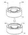
所述的抗冲击石英加速度计由表头和伺服回路组成,加速度计表头包括上力矩器、下力矩器和位于上述两力矩器之间的粘有线圈的石英玻璃摆片,石英玻璃摆片包括支承环、挠性梁、摆和六个支承凸台,支承环位于摆片外缘,为圆环状结构,支承环上正反两面共有六个支承凸台,石英摆片的中部为半圆状的摆,摆通过两个方形的薄挠性梁与支承环相连,在沿输出轴方向上在所述的石英玻璃摆片的支承环和摆之间加有限制石英玻璃摆片变形的限位结构。The impact-resistant quartz accelerometer is composed of a head and a servo loop. The head of the accelerometer includes an upper torque device, a lower torque device and a quartz glass pendulum plate with a coil attached between the above two torque devices. The quartz glass pendulum plate It includes a supporting ring, a flexible beam, a pendulum and six supporting bosses. The supporting ring is located on the outer edge of the pendulum piece and has a circular structure. There are six supporting bosses on the front and back sides of the supporting ring. The middle part of the quartz pendulum piece is a semicircle Shaped pendulum, the pendulum is connected with the support ring through two square thin flexible beams, along the direction of the output shaft, there is a limiter to limit the deformation of the quartz glass pendulum piece between the support ring and the pendulum. bit structure.
本发明与现有技术相比的优点在于:由于采用全固态数字闭环光纤陀螺、抗冲击石英加速度计和本体薄壁加筋金属合金结构,使本发明在对外连接无需任何减振的情况下,能够承受恶劣的冲击、振动等力学环境条件并保持较好精度,同时也使惯性测量系统保持了安装精度的长期稳定性,提高了惯性测量系统的综合性能。Compared with the prior art, the present invention has the advantages of: due to the use of all solid-state digital closed-loop fiber optic gyroscope, impact-resistant quartz accelerometer and thin-walled metal alloy structure of the body, the present invention does not require any vibration reduction for external connections. It can withstand harsh mechanical environment conditions such as shock and vibration and maintain good accuracy. At the same time, it also enables the inertial measurement system to maintain long-term stability of installation accuracy and improves the overall performance of the inertial measurement system.
附图说明 Description of drawings
图1为本发明的结构组成原理框图;Fig. 1 is a structural composition principle block diagram of the present invention;
图2为图1中的光纤陀螺原理框图;Fig. 2 is a schematic block diagram of the fiber optic gyroscope in Fig. 1;
图3图2中的FPGA逻辑电路原理框图;The schematic block diagram of the FPGA logic circuit in Fig. 3 Fig. 2;
图4为图1中石英加速度计的结构示意图;Fig. 4 is the structural representation of quartz accelerometer among Fig. 1;
图5为图4中加有限位凸台的石英玻璃摆片外形示意图;Fig. 5 is the schematic diagram of the appearance of the quartz glass pendulum plate with the limited boss added in Fig. 4;
图6为图4中加有限位销钉的下力矩器顶视图;Fig. 6 is the top view of the lower torque device with limit pin added in Fig. 4;
图7为图4中加有限位销钉的力矩器结构示意图;Fig. 7 is a schematic diagram of the structure of the torque device with limit pins added in Fig. 4;
图8为图1中石英加速度计装配后,限位销钉与摆片之间的位置关系图;Fig. 8 is a diagram of the positional relationship between the limit pin and the swing plate after the quartz accelerometer in Fig. 1 is assembled;
图9为现有的石英加速度计挠性梁在250g输出轴方向加速度作用下,最大拉应力示意图;Fig. 9 is a schematic diagram of the maximum tensile stress of the existing quartz accelerometer flexible beam under the action of acceleration in the direction of the output axis of 250g;
图10为本发明中的抗冲击石英加速度计挠性梁在250g输出轴方向加速度作用下,最大拉应力示意图;Fig. 10 is a schematic diagram of the maximum tensile stress of the shock-resistant quartz accelerometer flexible beam of the present invention under the action of acceleration in the direction of the output axis of 250g;
图11为本发明中的光纤陀螺在10~2000Hz/8g正弦扫描下的输出曲线。Fig. 11 is the output curve of the fiber optic gyroscope in the present invention under 10-2000Hz/8g sine sweep.
具体实施方式 Detailed ways
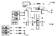
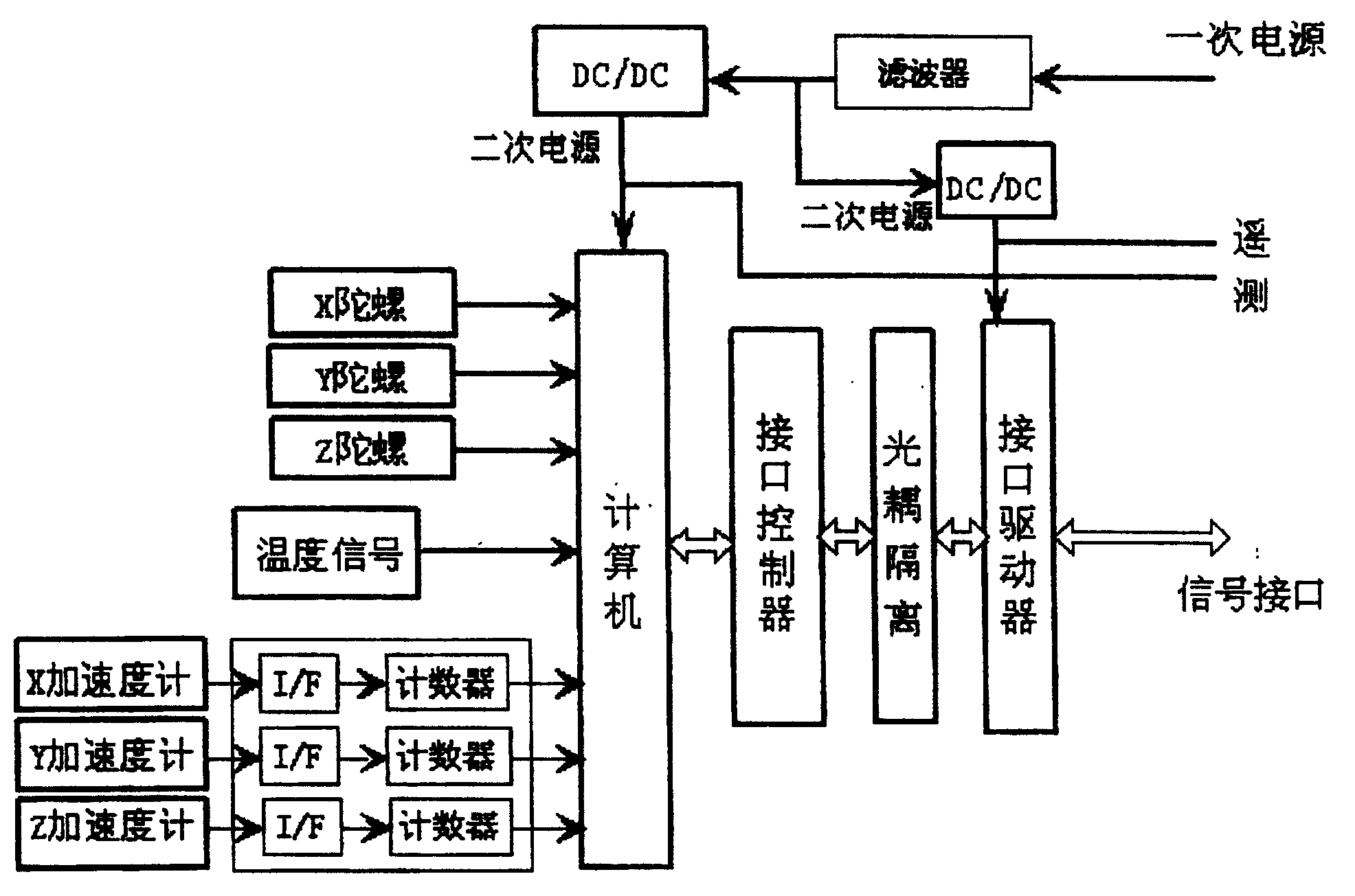
如图1所示,本发明具有高抗振性能的光纤陀螺惯性测量系统主要包括三只光纤陀螺、三只石英加速度计、本体结构等,其中采用正交放置的三个光纤陀螺完成被测体坐标系三个轴的角速度测量,三个光纤陀螺采用全固态数字闭环光纤陀螺;三个石英加速度计正交放置完成被测体坐标系三个轴的加速度测量,三个石英加速度计采用抗冲击石英加速度计;计算机实现信号处理,它在4ms周期内完成从陀螺和加速度计信号取样、误差补偿,发送数据给被测体上计算机和遥测系统的功能,具有高速采集、处理、传输功能;二次电源把一次电源变换为上述部件所需的直流电源;本体结构用于安装上述部件,它采用薄壁加筋铝合金或镁合金金属合金或铝基复合材料等,要保证光纤陀螺和加速度计敏感轴三轴正交性,提供电磁屏蔽与减振功能,保证需要的刚度。提供与被测体的连接基准和连接孔,同时使得整个惯性测量系统对外连接不需减振器而能满足恶劣的力学环境要求。As shown in Figure 1, the fiber optic gyroscope inertial measurement system with high anti-vibration performance of the present invention mainly includes three fiber optic gyroscopes, three quartz accelerometers, a body structure, etc., wherein three fiber optic gyroscopes placed orthogonally are used to complete the coordinate system of the measured body Three-axis angular velocity measurement, three fiber optic gyroscopes adopt all-solid-state digital closed-loop fiber optic gyroscope; three quartz accelerometers are placed orthogonally to complete three-axis acceleration measurement of the measured body coordinate system, and three quartz accelerometers adopt shock-resistant quartz accelerometers The computer implements signal processing, which completes sampling from the gyroscope and accelerometer signals, error compensation, and sends data to the computer and telemetry system on the measured body within a period of 4ms. It has high-speed acquisition, processing, and transmission functions; secondary power supply Convert the primary power supply to the DC power required by the above components; the main body structure is used to install the above components, it is made of thin-walled reinforced aluminum alloy or magnesium alloy metal alloy or aluminum matrix composite materials, etc., to ensure that the optical fiber gyro and accelerometer sensitive axis The three-axis orthogonality provides electromagnetic shielding and vibration reduction functions to ensure the required rigidity. It provides the connection datum and connection hole with the measured body, and at the same time makes the external connection of the entire inertial measurement system not require a shock absorber and can meet the harsh mechanical environment requirements.
光纤陀螺是利用光纤构成的一种环状干涉仪,属纯光学、静止型陀螺,从本质上摆脱了转子陀螺的范畴,无运动部件,全固体化,抗振和抗冲击性能基础好;但是内部光纤细而轻,缠绕在轴上和散布在腔内的光纤如果不加以合理固定,极易在振动和冲击等过程中发生位移或受到应力,影响光信号在光路中传输,从而影响光纤陀螺的性能;光纤经过合理的加固处理后,在振动条件下就可以保持初始位置,光信号在光路中传输时就不会受到影响,因而全固态化的光纤陀螺,具有优良的抗振和抗冲击性能。Fiber optic gyroscope is a kind of annular interferometer composed of optical fiber. It is a pure optical and static gyroscope. It is essentially out of the category of rotor gyroscope. It has no moving parts, is fully solidified, and has a good foundation for anti-vibration and shock resistance; but The internal optical fiber is thin and light. If the optical fiber wound on the axis and scattered in the cavity is not properly fixed, it is easy to be displaced or stressed during vibration and impact, which will affect the transmission of optical signals in the optical path, thereby affecting the optical fiber gyroscope. Excellent performance; After reasonable reinforcement, the optical fiber can maintain the initial position under vibration conditions, and the optical signal will not be affected when it is transmitted in the optical path. Therefore, the all-solid-state optical fiber gyroscope has excellent anti-vibration and shock resistance performance.
为了满足小型化的要求,本体结构设计时体积和质量受到很大的限制,安装仪表的部位壁很薄,强度和刚度不足,抗振性能差,在采用加筋结构后抗振性能得到了一定的提高,但是还不能完全满足要求,在结构限制无法突破的情况下,必须采用新型密度小、具有更高比强度和比高度的结构材料来取代传统的LY12结构材料。本实施例的本体结构采用Al/SiCp铝基复合材料后,其密度与LY12接近,但强度和刚度高,在同样壁厚的情况下抗振性能大大提高;同时本体外罩采用密度更小的镁合金材料,不仅质量轻,还具有吸振性能和电磁屏蔽性能。In order to meet the requirements of miniaturization, the volume and quality of the main body structure design are greatly limited, the wall of the part where the instrument is installed is very thin, the strength and rigidity are insufficient, and the vibration resistance is poor. After adopting the reinforced structure, the vibration resistance has been improved to a certain extent. However, the requirements cannot be fully met. In the case of structural limitations that cannot be broken through, new structural materials with low density, higher specific strength and specific height must be used to replace the traditional LY12 structural material. After the body structure of this embodiment adopts Al/SiCp aluminum-based composite material, its density is close to that of LY12, but its strength and rigidity are high, and the anti-vibration performance is greatly improved under the same wall thickness; at the same time, the body cover is made of magnesium with a lower density Alloy materials are not only light in weight, but also have vibration-absorbing properties and electromagnetic shielding properties.
如图2所示,本发明采用的全固态数字闭环光纤陀螺由光路部分和电路部分组成,光路部分由宽带光源1、光纤耦合器2、光电探测器5、多功能集成光学芯片3和光纤环4构成,从宽带光源1发出的光,经光纤耦合器2和多功能集成光学芯片3后分成两束,分别按顺时针和逆时针外方向沿光纤环4传输,并在多功能集成光学芯片3的Y分支的合光点上发生干涉相位差,多功能集成光学芯片3作为相位调制器将此相位差调制后返回经过光纤耦合器2到达光电探测器5;电路部分由前置放大和滤波电路6、A/D转换7、FPGA逻辑电路8、对FPGA逻辑电路产生的数字信号进行数模转换的D/A转换器9及对FPGA逻辑电路产生的2复位数字补偿信号的进行数模转换的D/A转换器10及增益控制电路15组成,放大滤波电路6对光电探测器5输出的信号进行前置放大和选通滤波,并通过A/D转换器7进行模数转换后,送入FPGA逻辑电路8对数字量进行处理,并存贮陀螺的输出信号,同时其产生的方波调制信号和数字相位阶梯波反馈信号叠加之和进行经过D/A转换9,输入到增益控制器15中,由增益控制15调整增益幅后将方波调制信号和数字相位阶梯波反馈信号之和加到多功能集成光学芯片3的一臂上。As shown in Figure 2, the all-solid-state digital closed-loop fiber optic gyro used in the present invention is composed of an optical path part and a circuit part, and the optical path part is composed of a broadband light source 1, an optical fiber coupler 2, a photodetector 5, a multifunctional integrated optical chip 3 and a fiber optic ring 4, the light emitted from the broadband light source 1 is divided into two beams after passing through the fiber coupler 2 and the multifunctional integrated optical chip 3, and then transmitted along the optical fiber ring 4 in clockwise and counterclockwise directions respectively, and then passed through the multifunctional integrated optical chip Interference phase difference occurs at the light-combining point of the Y branch of 3, and the multifunctional integrated optical chip 3 acts as a phase modulator to modulate the phase difference and then returns to the photodetector 5 through the fiber coupler 2; the circuit part is composed of preamplification and filtering Circuit 6, A/D conversion 7, FPGA logic circuit 8, D/A converter 9 for digital-to-analog conversion of the digital signal generated by the FPGA logic circuit and digital-to-analog conversion of the 2 reset digital compensation signals generated by the FPGA logic circuit The D/A converter 10 and the gain control circuit 15 are composed of the D/A converter 10 and the gain control circuit 15. The amplification filter circuit 6 carries out pre-amplification and gate filtering to the signal output by the photodetector 5, and after the analog-to-digital conversion is carried out by the A/
如图3所示,FPGA逻辑电路8主要由数字解调80、加法器81、存储器82、速率寄存器83、加法器84、存储器85、加法器86、晶振88、分频器87组成,其中数字解调80、加法器81和存储器82完成对多功能集成光学芯片3输出的调制误差信号的数字回路积分功能,产生数字相位阶梯波的高度;寄存器83、加法器84和存储器85完成对数字回路积分后的信号进行二次积分,产生数字相位阶梯波,加法器86将将晶振88和分频器87产生的方波调制信号作为偏置调制与数字相位阶梯波叠加后加到多功能集成电路芯片3的一臂上,使光纤线圈中的顺时针和逆时针光波产生一个固定相位差(等于阶梯波的高度),抵消旋转引起的Sagnac相移,光纤陀螺始终工作在灵敏度最高的零个位差点附近,提高光纤陀螺的标度因数稳定性和动态范围,同时回路积分输出的旋转速率数字量存储在速率寄存器83中作为陀螺的输出值。As shown in Figure 3, the FPGA logic circuit 8 is mainly composed of a digital demodulator 80, an adder 81, a memory 82, a rate register 83, an adder 84, a memory 85, an adder 86, a crystal oscillator 88, and a frequency divider 87. Demodulation 80, adder 81 and memory 82 complete the digital circuit integration function of the modulation error signal output by the multifunctional integrated
此外,光纤陀螺小型化设计,也是提高光纤陀螺抗振性能的结构基础,因为通过小型化刚性设计,可以大大提高光纤陀螺的谐振频率。因此,本发明将图2中的光纤线圈4的长度减少为300m,尽可能扩大其曲率半径,光纤线圈4的骨架直径尺寸为φ76mm,而且改进光纤对接技术,采用套管保护,尽可能节省空间,同时电路设计分成模拟、数字电路板上下两块安装,有效降低了陀螺直径,经过设计后,本发明的光纤陀螺尺寸为φ78mm×49mm。之后,将光纤陀螺光路部分全部用硅橡胶填充,并进行固化封装,光纤线圈4采用局部硅橡胶加固。In addition, the miniaturization design of the fiber optic gyroscope is also the structural basis for improving the anti-vibration performance of the fiber optic gyroscope, because the resonant frequency of the fiber optic gyroscope can be greatly increased through the miniaturized rigid design. Therefore, the present invention reduces the length of the optical fiber coil 4 in Fig. 2 to 300m, expands its radius of curvature as much as possible, the skeleton diameter of the optical fiber coil 4 is φ76mm, and improves the optical fiber docking technology, adopts sleeve protection, saves space as much as possible At the same time, the circuit design is divided into analog and digital circuit boards for installation, which effectively reduces the diameter of the gyroscope. After design, the size of the fiber optic gyroscope of the present invention is φ78mm×49mm. Afterwards, the optical path of the fiber optic gyroscope is completely filled with silicon rubber, and cured and packaged, and the fiber optic coil 4 is partially reinforced with silicon rubber.
如图4、5所示,本发明中的抗冲击石英加速度计由上力矩器11、下力矩器14、粘有线圈13的石英玻璃摆片12组成,石英玻璃摆片12包括支承环21、挠性梁22、摆23、正反两面六个支承凸台24和限位凸台25,支承环21位于摆23外缘,为圆环状结构,支承环21正反两面共有六个支承凸台24,并具有两个限位凸台25,石英摆片12的中部为半圆状的摆23,摆23通过两个方形的很薄的挠性梁22与支承环21相连,在摆23与支承环21之间具有一定的间隙,两个限位凸台25处在支承环21与摆23之间的间隙之中。As shown in Figures 4 and 5, the anti-shock quartz accelerometer among the present invention is made up of
如图6、7、8所示,本发明的抗冲击石英加速度计的另一结构,它由上力矩器11、下力矩器14、粘有线圈13的石英玻璃摆片12组成,石英玻璃摆片12包括支承环21、挠性梁22、摆23、六个支承凸台24,支承环21位于摆23外缘,为圆环状结构,上面正反两面共有六个支承凸台24,石英摆片12的中部为半圆状的摆23,摆23通过两个方形的很薄的挠性梁22与支承环21相连,在摆23与支承环21之间具有一定的间隙,下力矩器14具有限位销钉141,限位销钉141位于同支承环21与摆23之间的间隙相对的位置。仪表装配时,粘有线圈13的石英玻璃摆片12固定在上下力矩器之间,由于限位销钉141同支承环21与摆23之间的气隙相对,装配后限位销钉141处在支承环21与摆23之间的间隙中。上述抗冲击石英加速度计的两实施例中的限位凸台25或限位销钉41与摆23之间的间隙为As shown in Figures 6, 7, and 8, another structure of the shock-resistant quartz accelerometer of the present invention is composed of an
其中,δb为挠性梁应力等于材料极限强度时,摆的变形;nb为安全系数。在本实施例中,挠性梁应力等于材料极限强度时,摆的变形δb=0.05mm,安全系数nb=1.3,间隙δ≈0.04mm。Among them, δ b is the deformation of the pendulum when the stress of the flexible beam is equal to the ultimate strength of the material; n b is the safety factor. In this embodiment, when the stress of the flexible beam is equal to the ultimate strength of the material, the deformation of the pendulum δ b =0.05mm, the safety factor n b =1.3, and the gap δ≈0.04mm.
图9所示为使用现有石英玻璃摆片,加速度计挠性梁在250g输出轴方向加速度作用下,最大应力的计算结果。挠性梁的最大应力为7.159×10⁷Pa,已超过石英玻璃材料的抗拉强度5×10⁷Pa,因此挠性梁将发生断裂。Figure 9 shows the calculation results of the maximum stress of the accelerometer flexible beam under the action of 250g acceleration in the direction of the output axis using the existing quartz glass pendulum. The maximum stress of the flexible beam is 7.159×10 7 Pa, which has exceeded the tensile strength of the quartz glass material by 5×10 7 Pa, so the flexible beam will break.
图10所示为本发明的加有限位结构的石英玻璃摆片,加速度计挠性梁在250g输出轴方向加速度作用下,最大应力的计算结果。由于限位结构的保护,挠性梁的最大应力被限为3.898×10⁷Pa,小于石英玻璃的抗拉强度5×10⁷Pa,挠性梁不会损坏。试验表明,抗冲击石英加速度计可以承受250g的半正弦跌落式冲击,为惯性测量系统的抗振提供了基本保障。Fig. 10 shows the calculation results of the maximum stress of the flexible beam of the accelerometer under the acceleration of 250g in the direction of the output axis of the quartz glass pendulum plate with a limiting structure of the present invention. Due to the protection of the limiting structure, the maximum stress of the flexible beam is limited to 3.898×10 7 Pa, which is less than the tensile strength of quartz glass 5×10 7 Pa, and the flexible beam will not be damaged. Tests have shown that the shock-resistant quartz accelerometer can withstand a 250g half-sine drop shock, which provides a basic guarantee for the vibration resistance of the inertial measurement system.
经过以上各措施,大大提高了光纤陀螺的抗振动冲击能力,达到了冲击试验可承受100g的量级,过载试验可承受55g的量级,正弦扫描振动10~2000Hz/8g,振动条件下保持精度,2000Hz内无谐振等优良抗振性能。图11中给出了光纤陀螺在正弦扫描振动试验中的输出曲线。Through the above measures, the anti-vibration and shock ability of the fiber optic gyroscope has been greatly improved, reaching the level of 100g for shock test, 55g for overload test, 10-2000Hz/8g for sinusoidal scanning vibration, and maintaining accuracy under vibration conditions , Excellent anti-vibration performance such as no resonance within 2000Hz. Figure 11 shows the output curve of the fiber optic gyroscope in the sinusoidal scanning vibration test.
采用全固态光纤陀螺和抗冲击石英加速计及本体薄壁加筋金属合金结构以后,惯性测量系统对外连接无需减振器,而是直接刚性相连,在表1所示的恶劣力学环境下,能够保持精度和稳定性;并且由于不存在非金属弹性连接,使惯性测量系统能够长期保持安装精度,保证可靠性和长期稳定性,在长期贮存条件下,有利于始终保持初始标定精度。After adopting the all-solid-state fiber optic gyroscope, the impact-resistant quartz accelerometer and the thin-walled reinforced metal alloy structure of the body, the external connection of the inertial measurement system does not require a shock absorber, but is directly connected rigidly. Under the harsh mechanical environment shown in Table 1, it can Maintain accuracy and stability; and because there is no non-metallic elastic connection, the inertial measurement system can maintain installation accuracy for a long time, ensuring reliability and long-term stability. Under long-term storage conditions, it is conducive to maintaining the initial calibration accuracy.
表1光纤陀螺惯性测量系统力学环境条件Table 1 Mechanical environment conditions of the fiber optic gyroscope inertial measurement system
采用本发明前的光纤陀螺惯性测量系统在表1所示的随机振动条件下其振动中与振动前的零偏值比较相差很大,表2列出了这套光纤陀螺惯性测量系统随机振动试验振前、振中、振后零偏变化的比较,以其中的X轴为例,振动前陀螺仪的零偏值为1.3546°/h,振动中陀螺仪的零偏值为-17.3922°/h,振动前与振动中的零偏值变化为18.7468°/h,精度变化很大,不能满足零偏值变化<10°/h的使用要求;振动前加速度计的零偏值为0.0046g,振动中加速度计的零偏值为-0.8422g,振动前与振动中的零偏值变化为0.8468g,精度变化很大,不能满足零偏值变化<0.002g的使用要求,说明此方向抗振性能不好。其它方向的分析结果与此结论相同。Adopting the fiber optic gyroscope inertial measurement system before the present invention is compared with the zero bias value before the vibration in its vibration under the random vibration condition shown in table 1 and differs greatly, and table 2 has listed this set of fiber optic gyroscope inertial measurement system random vibration test Comparison of zero bias changes before, during and after vibration, taking the X axis as an example, the zero bias value of the gyroscope before vibration is 1.3546°/h, and the zero bias value of the gyroscope during vibration is -17.3922°/h , the change of zero bias before and during vibration is 18.7468°/h, and the precision changes greatly, which cannot meet the requirement of zero bias change <10°/h; the zero bias of the accelerometer before vibration is 0.0046g, and the vibration The zero bias value of the medium accelerometer is -0.8422g, and the zero bias value change between before vibration and during vibration is 0.8468g, and the accuracy changes greatly, which cannot meet the use requirements of zero bias value change <0.002g, indicating the anti-vibration performance in this direction not good. The analysis results in other directions are the same as this conclusion.
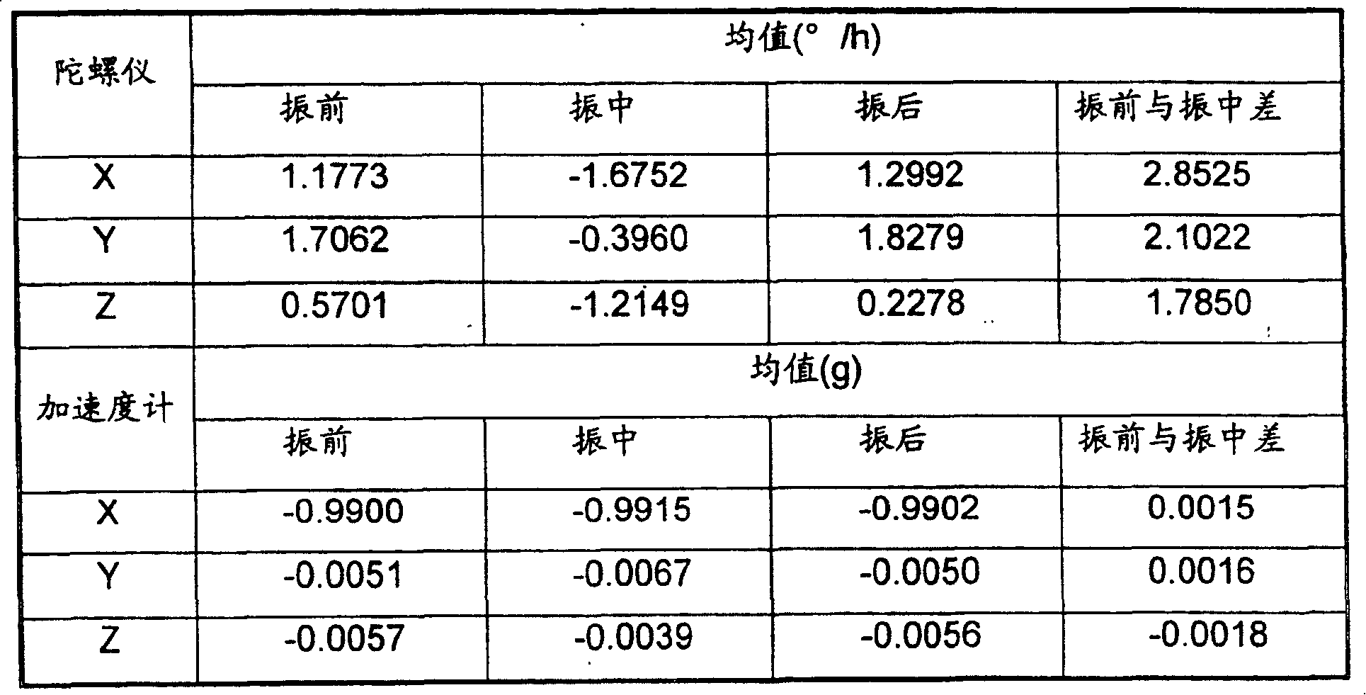
采用本发明后的光纤陀螺惯性测量系统已经研制了数十套,都经过了大量力学环境试验的考核,表3列出了其中一套光纤陀螺惯性测量系统在表1所示随机振动条件下进行试验的振前、振中、振后零偏变化的比较,同样以其中的X轴为例进行说明,振动前陀螺仪的零偏值为1.1773°/h,振动中陀螺仪的零偏值为-1.6752°/h,振动前与振动中的零偏值变化为2.8525°/h,精度变化较小,完全满足零偏值变化<10°/h的使用要求;振动前加速度计的零偏值为-0.9900g,振动中加速度计的零偏值为-0.9915g,振动前与振动中的零偏值变化为0.0015g,满足零偏值变化<0.002g的使用要求。其它方向的分析结果与此结论相同,充分说明采用本发明后的光纤陀螺惯性测量系统具有良好的抗振性,环境适应性强,可靠性高,工程化程度得到了很大突破。The fiber optic gyroscope inertial measurement system after adopting the present invention has been developed dozens of sets, has passed through the assessment of a large amount of mechanical environment tests, and table 3 has listed wherein a set of fiber optic gyroscope inertial measurement system is carried out under the random vibration condition shown in table 1 The comparison of the zero bias changes before, during and after vibration in the test is also illustrated by taking the X axis as an example. The zero bias of the gyroscope before vibration is 1.1773°/h, and the zero bias of the gyroscope during vibration is 1.1773°/h. -1.6752°/h, the change of zero bias value before vibration and during vibration is 2.8525°/h, the accuracy change is small, fully meet the use requirements of zero bias value change <10°/h; the zero bias value of the accelerometer before vibration It is -0.9900g, the zero bias value of the accelerometer during vibration is -0.9915g, and the change of zero bias value before vibration and during vibration is 0.0015g, which meets the use requirement of zero bias value change <0.002g. The analysis results in other directions are the same as this conclusion, which fully demonstrates that the fiber optic gyroscope inertial measurement system adopted by the present invention has good vibration resistance, strong environmental adaptability, high reliability, and a great breakthrough in engineering degree.
表2采用本发明前的光纤陀螺惯性测量系统随机振动试验振前、振中、振后零偏比较Table 2 uses the fiber optic gyroscope inertial measurement system random vibration test before the present invention to compare the zero deviation before vibration, during vibration and after vibration
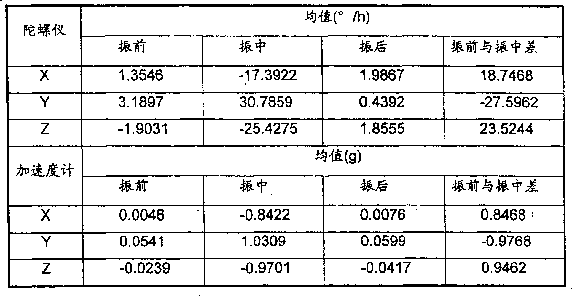
表3采用本发明后的光纤陀螺惯性测量系统随机振动试验振前、振中、振后零偏比较Table 3 Comparison of zero deviation before, during and after vibration of the fiber optic gyroscope inertial measurement system random vibration test after adopting the present invention
Claims (8)
Priority Applications (1)
| Application Number | Priority Date | Filing Date | Title |
|---|---|---|---|
| CNB2005100748564A CN100405015C (en) | 2005-06-07 | 2005-06-07 | A Fiber Optic Gyro Inertial Measurement System with High Vibration Resistance |
Applications Claiming Priority (1)
| Application Number | Priority Date | Filing Date | Title |
|---|---|---|---|
| CNB2005100748564A CN100405015C (en) | 2005-06-07 | 2005-06-07 | A Fiber Optic Gyro Inertial Measurement System with High Vibration Resistance |
Publications (2)
| Publication Number | Publication Date |
|---|---|
| CN1687708A CN1687708A (en) | 2005-10-26 |
| CN100405015C true CN100405015C (en) | 2008-07-23 |
Family
ID=35305750
Family Applications (1)
| Application Number | Title | Priority Date | Filing Date |
|---|---|---|---|
| CNB2005100748564A Expired - Lifetime CN100405015C (en) | 2005-06-07 | 2005-06-07 | A Fiber Optic Gyro Inertial Measurement System with High Vibration Resistance |
Country Status (1)
| Country | Link |
|---|---|
| CN (1) | CN100405015C (en) |
Families Citing this family (22)
| Publication number | Priority date | Publication date | Assignee | Title |
|---|---|---|---|---|
| CN1322312C (en) * | 2006-03-29 | 2007-06-20 | 北京航空航天大学 | Connected inertia measuring device of open-loop fibre-optical |
| CN100454059C (en) * | 2006-05-19 | 2009-01-21 | 北京航空航天大学 | A device for increasing the closed-loop bandwidth of an optical fiber gyroscope by triple frequency modulation |
| CN1888821B (en) * | 2006-07-28 | 2010-05-12 | 北京航空航天大学 | Light composite structure for space application of fiber optic gyroscope |
| CN1888822B (en) * | 2006-07-28 | 2010-05-12 | 北京航空航天大学 | A Fiber Optic Gyroscope Combination Test Platform Suitable for Space Applications |
| CN100449317C (en) * | 2006-11-08 | 2009-01-07 | 浙江大学 | High resolution sub-nanometer optical 3D accelerometer |
| CN101290227B (en) * | 2008-06-17 | 2010-12-29 | 北京航空航天大学 | Three axis optical fibre gyroscope inertia measurement unit integral structure |
| CN101915576B (en) * | 2010-07-13 | 2011-10-26 | 皮亚斌 | Optical fiber loop for optical fiber gyroscope |
| CN102435395B (en) * | 2011-09-01 | 2014-05-28 | 中国航空工业第六一八研究所 | Balance test mould and test method of flexible gyroscope inertia rotor component |
| CN102636169B (en) * | 2012-04-18 | 2014-07-09 | 北京航空航天大学 | Vehicle-mounted dynamic positioning and orientation device based on triaxial integrated high-precision fiber-optic gyroscope |
| CN102901495B (en) * | 2012-10-19 | 2015-06-03 | 重庆华渝电气仪表总厂 | Angular displacement optical fiber gyroscope |
| CN103076011B (en) * | 2012-12-26 | 2015-12-23 | 北京兴华机械厂 | A kind of micromechanical gyroscope combination for body stability contorting |
| CN103114845B (en) * | 2013-01-17 | 2016-01-27 | 北京航空航天大学 | A kind of optical fibre gyro IMU skeleton for oil inclinometer |
| CN103411615B (en) * | 2013-07-26 | 2015-11-11 | 北京航天控制仪器研究所 | The flexible quick-connecting inertia measurement system of a kind of two redundancy |
| CN104270140A (en) * | 2014-09-09 | 2015-01-07 | 张小亚 | Gateway wave generator composed of double hold amplifiers |
| CN104281757B (en) * | 2014-10-29 | 2017-06-30 | 中国电子科技集团公司第二十九研究所 | The electromechanical integral design method of antivibration crystal oscillator |
| CN110031653B (en) * | 2019-05-09 | 2021-07-27 | 保定开拓精密仪器制造有限责任公司 | Small signal sampling device of triaxial quartz flexible accelerometer and processing technology thereof |
| CN110174528B (en) * | 2019-05-09 | 2021-07-27 | 保定开拓精密仪器制造有限责任公司 | Anti-interference quartz flexible accelerometer signal sampling system and compensation calculation method |
| CN111089575B (en) * | 2019-12-13 | 2022-01-04 | 北京航天时代光电科技有限公司 | Micro-miniature optical fiber gyroscope packaging structure |
| CN111964660B (en) * | 2020-06-30 | 2023-02-28 | 北京航天时代光电科技有限公司 | Optical fiber gyroscope capable of independently resisting high-overload large impact in axial direction |
| CN114689084B (en) * | 2021-10-25 | 2025-11-07 | 北京航天时代光电科技有限公司 | Undistorted test method for dynamic error under fiber optic gyroscope line vibration and angular vibration |
| CN114018729B (en) * | 2021-11-02 | 2022-05-17 | 上海交通大学 | Micro-particle accelerating device based on MEMS technology |
| CN114993279B (en) * | 2022-08-03 | 2022-11-22 | 北京晨晶电子有限公司 | Quartz micromechanical gyroscope |
Citations (3)
| Publication number | Priority date | Publication date | Assignee | Title |
|---|---|---|---|---|
| JPS63132111A (en) * | 1986-11-21 | 1988-06-04 | Tokyo Keiki Co Ltd | Attitude detector |
| JP2000180171A (en) * | 1998-12-17 | 2000-06-30 | Tokin Corp | Attitude angle detector |
| JP2002161321A (en) * | 2000-11-21 | 2002-06-04 | Taiheiyo Cement Corp | Stage and housing for inertia device |
-
2005
- 2005-06-07 CN CNB2005100748564A patent/CN100405015C/en not_active Expired - Lifetime
Patent Citations (3)
| Publication number | Priority date | Publication date | Assignee | Title |
|---|---|---|---|---|
| JPS63132111A (en) * | 1986-11-21 | 1988-06-04 | Tokyo Keiki Co Ltd | Attitude detector |
| JP2000180171A (en) * | 1998-12-17 | 2000-06-30 | Tokin Corp | Attitude angle detector |
| JP2002161321A (en) * | 2000-11-21 | 2002-06-04 | Taiheiyo Cement Corp | Stage and housing for inertia device |
Non-Patent Citations (6)
| Title |
|---|
| 一种新颖的QUBIK惯性测量装置. 杨庭楣.系统工程与电子技术,第5期. 1991 |
| 一种新颖的QUBIK惯性测量装置. 杨庭楣.系统工程与电子技术,第5期. 1991 * |
| 光纤陀螺的研究评述. 程加斌,张炎华.光机电信息,第13卷第10期. 1996 |
| 光纤陀螺的研究评述. 程加斌,张炎华.光机电信息,第13卷第10期. 1996 * |
| 捷联惯导系统中的减震技术. 刘一谦,王世震,李红.飞航导弹,第8期. 1990 |
| 捷联惯导系统中的减震技术. 刘一谦,王世震,李红.飞航导弹,第8期. 1990 * |
Also Published As
| Publication number | Publication date |
|---|---|
| CN1687708A (en) | 2005-10-26 |
Similar Documents
| Publication | Publication Date | Title |
|---|---|---|
| CN100405015C (en) | A Fiber Optic Gyro Inertial Measurement System with High Vibration Resistance | |
| CN103256941B (en) | A kind of method that MEMS gyroscope is high-order temperature compensated | |
| CN111678538B (en) | An Error Compensation Method for Dynamic Level Meter Based on Velocity Matching | |
| CN103353310B (en) | A kind of laser near-net shaping | |
| CN102539832A (en) | Biaxially-resonant silicon-micromachined accelerometer structure in shape of Chinese character 'tian' | |
| CN101639541B (en) | Accelerometer relative gravity meter | |
| Wen et al. | An encoder-based relative attitude observation method for self-calibration in dual-axis RINS | |
| CN103389085A (en) | Six-redundancy-type optical fiber gyroscope IMU (inertial measurement unit) table body | |
| CN108089027A (en) | Sensor and navigation attitude instrument based on MEMS capacitive micro-acceleration gauge | |
| Cui et al. | Design and experiment of MEMS solid-state wave gyroscope quadrature error correction system | |
| Barone et al. | The UNISA folded pendulum: A very versatile class of low frequency high sensitive sensors | |
| CN106248078A (en) | Machine laser gyroscope shaking sensitive axes dynamic deflection error parameter is estimated and compensation method | |
| CN101082491A (en) | Pendulum type gyroscope north searching instrument measurement method | |
| CN108710001A (en) | Two axis one gyroaccelerometers of one kind and method of servo-controlling | |
| CN105841715B (en) | A highly dynamic dual-axis angular rate gyroscope bias and scale factor error compensation | |
| CN108072364A (en) | Micro-inertia measuring device | |
| Yang | Design of fiber optic gyro inertial measurement system with high vibration resistance | |
| Ren et al. | A new method for calibrating nonlinear coefficients of PIGA on linear vibrator | |
| US3413859A (en) | Digital rate gyro | |
| CN111006665A (en) | Atomic spin gyroscope strapdown system based on magnetic field feedback | |
| CN112963480B (en) | Controllable vibration reduction device and method of mechanically dithered laser gyro inertial navigation system | |
| Evstifeev et al. | Enhancing the mechanical resistance of micromechanical gyros | |
| Bogolyubov et al. | Astatic gyrocompass based on a hybrid micromechanical gyroscope | |
| Killen et al. | High acceleration, high performance solid state accelerometer development | |
| CN210803518U (en) | High-temperature-resistant quartz flexible acceleration sensor with high sealing structure |
Legal Events
| Date | Code | Title | Description |
|---|---|---|---|
| C06 | Publication | ||
| PB01 | Publication | ||
| C10 | Entry into substantive examination | ||
| SE01 | Entry into force of request for substantive examination | ||
| C14 | Grant of patent or utility model | ||
| GR01 | Patent grant | ||
| ASS | Succession or assignment of patent right |
Owner name: BEIJING SPACE AGE OPTICAL SCIENCE + TECHNOLOGY CO. Free format text: FORMER OWNER: CHINA AEROSPACE TIMES ELECTRONICS CORPORATION Effective date: 20090605 |
|
| C41 | Transfer of patent application or patent right or utility model | ||
| TR01 | Transfer of patent right |
Effective date of registration: 20090605 Address after: Beijing city Fengtai District Xiaotun Road No. 149 North Patentee after: BEIJING AEROSPACE TIMES OPTICAL-ELECTRONIC TECHNOLOGY Co.,Ltd. Address before: No. 52, Yongding Road, Beijing, Haidian District Patentee before: CHINA AEROSPACE TIMES ELECTRONIC Corp. |
|
| CX01 | Expiry of patent term | ||
| CX01 | Expiry of patent term |
Granted publication date: 20080723 |