CN100400243C - Jacket fastener without using tools - Google Patents
Jacket fastener without using tools Download PDFInfo
- Publication number
- CN100400243C CN100400243C CNB011217294A CN01121729A CN100400243C CN 100400243 C CN100400243 C CN 100400243C CN B011217294 A CNB011217294 A CN B011217294A CN 01121729 A CN01121729 A CN 01121729A CN 100400243 C CN100400243 C CN 100400243C
- Authority
- CN
- China
- Prior art keywords
- chuck
- spanner
- nut
- executive component
- electric tool
- Prior art date
- Legal status (The legal status is an assumption and is not a legal conclusion. Google has not performed a legal analysis and makes no representation as to the accuracy of the status listed.)
- Expired - Fee Related
Links
Images


Classifications
-
- B—PERFORMING OPERATIONS; TRANSPORTING
- B23—MACHINE TOOLS; METAL-WORKING NOT OTHERWISE PROVIDED FOR
- B23B—TURNING; BORING
- B23B31/00—Chucks; Expansion mandrels; Adaptations thereof for remote control
- B23B31/001—Protection against entering of chips or dust
-
- B—PERFORMING OPERATIONS; TRANSPORTING
- B23—MACHINE TOOLS; METAL-WORKING NOT OTHERWISE PROVIDED FOR
- B23B—TURNING; BORING
- B23B31/00—Chucks; Expansion mandrels; Adaptations thereof for remote control
- B23B31/02—Chucks
- B23B31/10—Chucks characterised by the retaining or gripping devices or their immediate operating means
- B23B31/12—Chucks with simultaneously-acting jaws, whether or not also individually adjustable
- B23B31/20—Longitudinally-split sleeves, e.g. collet chucks
- B23B31/201—Characterized by features relating primarily to remote control of the gripping means
- B23B31/2012—Threaded cam actuator
- B23B31/20125—Axially fixed cam, moving jaws
-
- B—PERFORMING OPERATIONS; TRANSPORTING
- B25—HAND TOOLS; PORTABLE POWER-DRIVEN TOOLS; MANIPULATORS
- B25D—PERCUSSIVE TOOLS
- B25D17/00—Details of, or accessories for, portable power-driven percussive tools
- B25D17/20—Devices for cleaning or cooling tool or work
-
- B—PERFORMING OPERATIONS; TRANSPORTING
- B23—MACHINE TOOLS; METAL-WORKING NOT OTHERWISE PROVIDED FOR
- B23B—TURNING; BORING
- B23B2231/00—Details of chucks, toolholder shanks or tool shanks
- B23B2231/20—Collet chucks
- B23B2231/2081—Keys, spanners or wrenches to operate the collet chuck
-
- B—PERFORMING OPERATIONS; TRANSPORTING
- B23—MACHINE TOOLS; METAL-WORKING NOT OTHERWISE PROVIDED FOR
- B23B—TURNING; BORING
- B23B2260/00—Details of constructional elements
- B23B2260/078—Hand tools used to operate chucks or to assemble, adjust or disassemble tools or equipment used for turning, boring or drilling
-
- B—PERFORMING OPERATIONS; TRANSPORTING
- B23—MACHINE TOOLS; METAL-WORKING NOT OTHERWISE PROVIDED FOR
- B23B—TURNING; BORING
- B23B2270/00—Details of turning, boring or drilling machines, processes or tools not otherwise provided for
- B23B2270/60—Prevention of rotation
-
- Y—GENERAL TAGGING OF NEW TECHNOLOGICAL DEVELOPMENTS; GENERAL TAGGING OF CROSS-SECTIONAL TECHNOLOGIES SPANNING OVER SEVERAL SECTIONS OF THE IPC; TECHNICAL SUBJECTS COVERED BY FORMER USPC CROSS-REFERENCE ART COLLECTIONS [XRACs] AND DIGESTS
- Y10—TECHNICAL SUBJECTS COVERED BY FORMER USPC
- Y10T—TECHNICAL SUBJECTS COVERED BY FORMER US CLASSIFICATION
- Y10T279/00—Chucks or sockets
- Y10T279/17—Socket type
- Y10T279/17411—Spring biased jaws
- Y10T279/17529—Fixed cam and moving jaws
- Y10T279/17538—Threaded-sleeve actuator
-
- Y—GENERAL TAGGING OF NEW TECHNOLOGICAL DEVELOPMENTS; GENERAL TAGGING OF CROSS-SECTIONAL TECHNOLOGIES SPANNING OVER SEVERAL SECTIONS OF THE IPC; TECHNICAL SUBJECTS COVERED BY FORMER USPC CROSS-REFERENCE ART COLLECTIONS [XRACs] AND DIGESTS
- Y10—TECHNICAL SUBJECTS COVERED BY FORMER USPC
- Y10T—TECHNICAL SUBJECTS COVERED BY FORMER US CLASSIFICATION
- Y10T409/00—Gear cutting, milling, or planing
- Y10T409/30—Milling
- Y10T409/303752—Process
-
- Y—GENERAL TAGGING OF NEW TECHNOLOGICAL DEVELOPMENTS; GENERAL TAGGING OF CROSS-SECTIONAL TECHNOLOGIES SPANNING OVER SEVERAL SECTIONS OF THE IPC; TECHNICAL SUBJECTS COVERED BY FORMER USPC CROSS-REFERENCE ART COLLECTIONS [XRACs] AND DIGESTS
- Y10—TECHNICAL SUBJECTS COVERED BY FORMER USPC
- Y10T—TECHNICAL SUBJECTS COVERED BY FORMER US CLASSIFICATION
- Y10T409/00—Gear cutting, milling, or planing
- Y10T409/30—Milling
- Y10T409/30392—Milling with means to protect operative or machine [e.g., guard, safety device, etc.]
-
- Y—GENERAL TAGGING OF NEW TECHNOLOGICAL DEVELOPMENTS; GENERAL TAGGING OF CROSS-SECTIONAL TECHNOLOGIES SPANNING OVER SEVERAL SECTIONS OF THE IPC; TECHNICAL SUBJECTS COVERED BY FORMER USPC CROSS-REFERENCE ART COLLECTIONS [XRACs] AND DIGESTS
- Y10—TECHNICAL SUBJECTS COVERED BY FORMER USPC
- Y10T—TECHNICAL SUBJECTS COVERED BY FORMER US CLASSIFICATION
- Y10T409/00—Gear cutting, milling, or planing
- Y10T409/30—Milling
- Y10T409/304088—Milling with means to remove chip
-
- Y—GENERAL TAGGING OF NEW TECHNOLOGICAL DEVELOPMENTS; GENERAL TAGGING OF CROSS-SECTIONAL TECHNOLOGIES SPANNING OVER SEVERAL SECTIONS OF THE IPC; TECHNICAL SUBJECTS COVERED BY FORMER USPC CROSS-REFERENCE ART COLLECTIONS [XRACs] AND DIGESTS
- Y10—TECHNICAL SUBJECTS COVERED BY FORMER USPC
- Y10T—TECHNICAL SUBJECTS COVERED BY FORMER US CLASSIFICATION
- Y10T409/00—Gear cutting, milling, or planing
- Y10T409/30—Milling
- Y10T409/306216—Randomly manipulated, work supported, or work following device
- Y10T409/306552—Randomly manipulated
- Y10T409/306608—End mill [e.g., router, etc.]
-
- Y—GENERAL TAGGING OF NEW TECHNOLOGICAL DEVELOPMENTS; GENERAL TAGGING OF CROSS-SECTIONAL TECHNOLOGIES SPANNING OVER SEVERAL SECTIONS OF THE IPC; TECHNICAL SUBJECTS COVERED BY FORMER USPC CROSS-REFERENCE ART COLLECTIONS [XRACs] AND DIGESTS
- Y10—TECHNICAL SUBJECTS COVERED BY FORMER USPC
- Y10T—TECHNICAL SUBJECTS COVERED BY FORMER US CLASSIFICATION
- Y10T409/00—Gear cutting, milling, or planing
- Y10T409/30—Milling
- Y10T409/309352—Cutter spindle or spindle support
Abstract
A collet assembly for a tool comprising a collet nut rotatably connectable to the tool; a collet operatively connectable to the collet nut; and a collet wrench movably connected with the tool and engageable with the collet nut for tightening and loosening the collet.
Description
Technical field
Present invention relates in general to field of power tools.The present invention especially relate to a kind of be used to clamp such as the interchangeable tool fitting of drill bit and be provided with the dust treatment system need be with the chuck assembly of instrument.
Background technology
Various types of instruments need the user optionally to connect a tool fitting, as drill bit or lead bit.At specific operation or duration of work, may need to adopt various accessories and need the accessory that is worn or damage is changed.Therefore, hope can carry out demolition and replacement to these interchangeable tool fitting easily.Common two kinds of mechanical devices that are used for the clamping interchangeable parts are chuck and chuck.The mechanical device of jacket type has higher rotary speed, generally is more favourable with the jacket type mechanical device therefore.
In the jacket type clamper, the handle of tool fitting is inserted in the cavity of chuck.Chuck is a circle tube element with vertical cavity substantially.Chuck has an end at least, have a plurality of longitudinal extensions arc pawl equal angles be arranged on around the chuck circumference, and spaced apart by the otch of a plurality of longitudinal extensions.Can be with the inner end portion of chuck processing in an instrument output element (as axle, rotating shaft or axle), chuck also can be independent (being a barrel-shaped sometimes) element.
Installation one chuck nut or chuck ring on chuck.The chuck nut is screwed on the end of tool spindle or rotating shaft.The chuck nut down is screwed in the rotating shaft, makes the inner surface of chuck nut and/or axle around the tool fitting handle, push the pawl of chuck.So tool fitting just has been fixed in power tool shaft/rotating shaft.
When changing the accessory instrument, must unclamp nut, so that the clamping to tool fitting is expanded and unclamped to chuck.To the tightening and unscrew and partly to operate of chuck nut,, the size of chuck nut and shape come the chuck nut correctly tightened that to begin then to unclamp be very difficult and/or uncomfortable with hand but only making by hand.Therefore, just must adopt spanner or similar instrument in order on the chuck nut, to apply enough moment.
Under the situation that adopts throw or electric tool, when tightening or unscrew the chuck nut, must prevent the rotation of axle/rotating shaft, otherwise will be difficult to realize the relative motion between nut and the rotating rotating shaft.
Traditional situation is, tightening and unscrewing in the process, needs the operator to clamp axle/rotating shaft and chuck nut simultaneously with two independent spanners or similar tool.Just the axle fix in position time, apply a moment then to nut.This process is very clumsy, but also needs the weight of supporting tool itself, and this makes this tighten and to unscrew process more clumsy.
Recently, designed a kind of instrument, this instrument is provided with a locking mechanism, is used for axle/rotating shaft is locked with respect to tool outer casing.Therefore, adopt built-in axle lock just can prevent the rotation of axle simply.This electric tool is tightened and unscrewed the chuck nut only needs a spanner.For example in U.S. Pat 5,496, this situation has been described in 139 and US5,813,805.
Yet, also still be inconvenient even change tool fitting with a hand-operated tools.For example, when needs were changed a drill bit, tool operation person stopped the thing of his WKG working with regard to having to and goes for a spanner.The influence that this at work delay causes is very big, the laid dry device in the work progress of big construction project or reconstruction project for example, and speed of production is necessary at high speed.
Summary of the invention
Owing to need be used for producing the task of dust and chip in conjunction with many instruments of the present invention, therefore, the technical characterictic of wishing to append to these instruments can prevent that instrument from being made dirty by dust.
Therefore, an object of the present invention is to provide a kind of instrument with a chuck assembly, it allows the user to carry out installation or removal to accessory easily, and need not to adopt any hand-operated tools.
Another object of the present invention provides a kind of executive component with the chuck clasper that exposes and can hold with a firm grip, it has the advantage of enough mechanical aspects, make the operator can apply enough moment and tighten or unscrew the chuck nut, and need not to adopt hand-operated tools.
For achieving the above object,, provide a kind of chuck assembly that is used for instrument, having comprised according to one aspect of the invention:
One chuck nut links to each other with instrument rotationally;
One chuck operationally links to each other with the chuck nut; With
One chuck spanner links to each other with instrument movably, and can with the chuck nut engages so that fastening and unclamp chuck.
According to a further aspect of the invention, provide a kind of chuck assembly that links to each other with the instrument with an output element, this chuck assembly comprises:
One chuck nut is threaded with the output element of instrument, and has an axial cavity;
One chuck is set in the cavity of chuck nut at least in part, and has an axial cavity; With
One chuck spanner, be installed in rotation on the instrument, and can between bonding station and disengaged position, move, thereby make when the chuck spanner is in bonding station, the chuck spanner contacts with the chuck nut, and the rotation of chuck spanner can make chuck fastening and unclamp, and when the chuck spanner was in a disengaged position, the chuck spanner can not limit the chuck nut.
According to a further aspect of the invention, the tool fitting that provides a kind of handle to have handle is connected to the method on the throw with conventional jacket spanner, and this method comprises:
Handle inserts in the cavity of chuck;
The rotation of the axle in the restriction instrument;
One chuck nut is engaged with the chuck spanner of integral body; With
Rotate whole chuck spanner, so as the chuck nut to be carried out fastening, thereby chuck be pressed on handle around.
According to a further aspect of the invention, provide tool fitting that a kind of handle has a handle, having comprised from the method that the throw with whole chuck spanner disassembles:
The rotation of the axle in the restriction instrument;
One chuck nut is engaged with the chuck spanner of integral body;
Rotate whole chuck spanner,, thereby unclamp chuck the extruding around the handle so that unclamp the chuck nut;
Handle disassembles from the cavity of chuck.
According to a further aspect of the invention, provide a kind of electric tool, having comprised:
One shell;
One motor is positioned at this enclosure;
One power supply links to each other with motor;
One output element can link to each other with motor drivingly;
One starting element links to each other with power supply and motor, so that optionally apply electric power to motor;
One chuck assembly links to each other with output element, and this chuck assembly comprises:
One chuck nut links to each other with output element rotationally;
One chuck operationally links to each other with the chuck nut; With
One chuck spanner links to each other with shell movably, and can with the chuck nut engages so that chuck is carried out fastening and unclamp.
According to a further aspect of the invention, provide a kind of electric tool, having comprised:
One shell;
One motor is positioned at this enclosure;
One power supply links to each other with motor;
One output element can link to each other with motor drivingly;
One starting element links to each other with power supply and motor, so that optionally apply electric power to motor;
One chuck assembly comprises:
One chuck nut can be threaded with output element, and has an axial cavity;
One chuck is at least partially disposed in the cavity of chuck nut, and has an axial cavity; With
One chuck spanner, link to each other with shell movably, and can between bonding station and disengaged position, move, thereby make when the chuck spanner is positioned at this bonding station, the chuck spanner contacts with the chuck nut, and the rotation of chuck spanner can make chuck fastening and unclamp, and when the chuck spanner was positioned at disengaged position, the chuck spanner did not limit the chuck nut.
According to a further aspect of the invention, provide a kind of electric tool with dust treatment system, this electric tool comprises:
One shell;
One motor is positioned at this enclosure;
One power supply links to each other with motor;
One output element can link to each other with motor drivingly;
One starting element links to each other with power supply and motor, so that optionally apply electric power to motor;
One chuck assembly comprises that an executive component and being used to promotes the device that dust is discharged, otherwise these dusts can accumulate in the chuck assembly, and the device of this promotion dust discharge comprises:
Opening on the executive component is discharged from the chuck assembly to allow dust;
A junction, it has the size between instrument and the executive component, and the size of this connecting portion can allow dust to discharge from the chuck assembly;
One surface of executive component, this surface are looped around around the chuck spanner button basically, and size that should the surface can allow dust to discharge around from the chuck assembly along chuck spanner button.
According to a further aspect of the invention, provide a kind of electric tool that is used for driving rotationally the accessory instrument, having comprised:
One shell;
One motor is installed in this shell;
One power supply links to each other with motor;
One switch links to each other with power supply and motor, is used for optionally applying electric power to motor;
One output shaft can link to each other with motor drivingly;
One axle, have an axis, a front end and a rear end, the rear end of this axle links to each other with axle, the front end of axle has an inner surface and an outer surface, the front inner surface of axle limits an axial cavity, the part of this axial cavity is tapered backward inwardly, and the forward outer surface of axle has screw thread;
Wholeheartedly the axle lock links to each other with shell between the primary importance and the second place movably, and its central shaft lock does not limit the rotation of axle in primary importance, and in the second place, the axle lock limits the rotation of axle;
One chuck assembly comprises:
One roughly cylindrical circular chuck nut, this chuck nut has axial cavity, one rear end and a front end, one inner surface and an outer surface, the part of the front inner surface of chuck nut is tapered forward inwardly, the forward outer surface screw-threaded engagement of the part of the rear inner surface of chuck nut and axle;
One in a tubular form chuck roughly, it is arranged on inside, and between the front end and chuck nut of axle, this chuck has an axial cavity, the outstanding pawl in the outstanding pawl in a plurality of front portions and a plurality of rear portion, anterior outstanding pawl has the outer surface that is tapered forward and slidably engages with the front inner surface of chuck nut inwardly, and the outstanding pawl in rear portion has the outer surface that is tapered backward and slidably engages with the front inner surface of axle inwardly;
One roughly cylindrical circular executive component links to each other with shell rotationally, with axle, chuck and the coaxial setting of chuck nut, and partly around axle, chuck and chuck nut;
One chuck spanner plate, be installed in the executive component movably, and between bonding station and disengaged position, can radially slide, this plate has an interior periphery, this interior periphery limits an opening, this opening passes plate, plate is basically around the chuck nut, this opening has first and second portion, when operation tool, the chuck nut is free to rotate in the first of this opening, and this is corresponding to disengaged position, and second portion can with the chuck nut engages of rotating, this is corresponding to bonding station;
One spring is connected between executive component and the chuck spanner plate, is used under normal conditions chuck spanner plate being biased into disengaged position;
One chuck spanner button links to each other with chuck spanner plate, and is exposed to the outside, so that move into bonding station with handgrip chuck spanner plate, and the compression spring; With
The roughly cylindrical circular chuck clasper of one available grasped, it links to each other with executive component.
The purpose of these purposes of the present invention and other by a kind of have the conventional jacket spanner need not realize with the chuck assembly of instrument.This chuck spanner is installed in rotation on the instrument, is used to turn the chuck nut, so that tighten or loosen chuck.The chuck spanner can also move between bonding station and disengaged position, and at bonding station, the chuck spanner can turn the chuck nut, and at disengaged position, the chuck spanner does not limit the chuck nut, thereby does not disturb the normal rotation of chuck nut during the instrument running.The motion of chuck spanner between bonding station and disengaged position can be axial, radially, rotate or the combination between them.
The chuck spanner can be biased in the disengaged position, and this can realize by the device that a spring or other are used to apply biasing force.
One executive component can link to each other the chuck spanner with instrument.This executive component is supporting the chuck spanner, so that move between bonding station and disengaged position.Executive component also is installed on the instrument movably, is used for passing to the chuck spanner moving.But executive component can comprise the chuck clasper of that expose an and hand grip.By this chuck clasper, the operator can be rotationally and/or is axially moved this chuck spanner.
One chuck spanner button also can be set, be used for mobile chuck spanner between bonding station and disengaged position.
Itself can have several types the chuck spanner.It can be the design openend formula or blind end formula (boxlike spanner).As optional scheme, it can be a kind of chuck spanner with complex internal shape.This complicated shape can have two parts.First is corresponding with disengaged position, and during the normal running of instrument, the chuck nut can freely rotate in this primary importance.Second portion is corresponding with bonding station, and the surface configuration of second portion is made with the chuck nut and contacted and turn this chuck nut.
Chuck nut and/or can partly apply with non-cohesive material with the rotating shaft of its threaded engagement is to reduce to unclamp the required moment of chuck.This non-cohesive material can be, for example polytetrafluoroethylmaterial material.
The inner surface of chuck nut and rotating shaft can match with interchangeable chuck, and this interchangeable chuck has roughly the same external shape and size, but has different cavitys, are used to clamp the accessory with various diameters and geometry handle.
Of the present invention another is characterised in that the design that has improved the rotating shaft lock.The design of this improvement design and chuck spanner is similar, and can adopt open-end wrench or employing to have the spanner of one of described complicated shape.
Some adopts the work of rotary cutting tool and directional orientation tool, and for example laid dry cutting can produce dust, and these dusts can enter tool interior, and influence the operation of button and executive component.Therefore, another object of the present invention provide a kind of in dust or dirty environment are arranged, can prevent to make dirty need be with the chuck assembly of instrument.This purpose can realize that promptly this design can allow some dusts enter inevitably by a kind of like this design, and guarantees that these dusts that enter mechanical device can discharge, make dust can not accumulate to can the running of interference instrument degree.Following several essential characteristics and technology have been adopted in this design, dust treatment system of the common formation of these features and technology, and this essential characteristic and technology are as follows:
Between the parts that move mutually, adopted looser gap;
Avoid or reduce to occur inner dead space or fatal weakness because at the dead angle or the discharge of fatal weakness place dust very slow;
The action of moving-member moves to or shifts onto the exit position to dust along general flow channel by way of parenthesis;
Horizontal or vertical border between subassembly is provided with some through holes, so that dust can move;
Inner member does not closely cooperate with the whole interior periphery of shell or enclosing cover, thereby dust can be moved at these component ambients.
This dust Design of processing system scheme mainly is a kind of passive scheme.That is to say that this scheme is not to provide a kind of precision apparatus to force dust to be discharged.But avoid dirt accumulation, and rely on flowing of dust to discharge dust, this flowing is when operator's tool using, instrument at random on diverse location and direction Move tool caused.Can promote moving of dust by the mobile of parts with by the caused cooling blast of motor fan.At last, these prevent that the identical technical characterictic of dirt accumulation from also making easier cleaning when the needs cleaning means, for example, with compressed air dust are blown out.
Description of drawings
By below reading to the detailed description of embodiment, and with reference to accompanying drawing, other purpose and advantage can clearer understanding of the present invention.In these accompanying drawings,
Fig. 1 is the profile of electric tool, is provided with the chuck assembly that need not use instrument according to of the present invention in this electric tool.
Fig. 2 is the part enlarged drawing of electric tool shown in Figure 1;
Fig. 3 is the parts explosion of the electric tool with chuck shown in Figure 1;
Fig. 4 A is the schematic perspective view of the chuck nut among Fig. 1;
Fig. 4 B is the side view of the chuck nut among Fig. 4 A;
Fig. 4 C is the sectional view of the chuck nut among Fig. 4 A;
Fig. 5 is the schematic perspective view of the chuck among Fig. 1;
Fig. 6 is the front view according to an alternative embodiment of chuck spanner of the present invention;
Fig. 7 is the parts explosion according to an alternative embodiment of chuck assembly of the present invention;
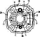
Fig. 8 is the external view of executive component;
Fig. 9 is the external view of front shell.
The specific embodiment
The invention provides a kind of chuck assembly that need not use instrument that is used for instrument.Although expressed the various embodiment that rotate cutting tool by accompanying drawing, those skilled in the art will appreciate that scope of the present invention is not limited thereto.In this, principle of the present invention is applicable to any any instrument that is provided with the chuck assembly that is used for clamping device accessory (as drill bit or driver etc.).
Referring now to accompanying drawing, in the accompanying drawings, element identical or that be equal to adopts identical Reference numeral to represent, especially sees figures.1.and.2, and has expressed an electric tool among the figure, and by Reference numeral 10 expressions.As an example, the specific power tool shown in the figure is a kind of rotation cutting or directional orientation tool 10, and it has a shell 12.It in shell 12 motor 14 that has cooling fan 15.Power supply links to each other with motor 14.In illustrated embodiment, motor 14 links to each other with power line 16 by switch 18.One output element links to each other with motor 14.In this case, motor drive shaft 20 directly links to each other with axle 22, thereby makes the speed rotation of annex (not shown) with motor.Perhaps, can in motor output, gear drive as known in the art be set, so that attachment is rotated with the speed different with motor speed.
Fig. 2 and Fig. 3 have expressed the enlarged drawing of the chuck spanner mechanism 23 and the member that links to each other.Expressed motor drive shaft 20 among the figure and supported by the bearing 26 in the support plate 27, support plate 27 is installed in the front shell 13.What be connected motor drive shaft 20 front ends is an axle 22.An axle locking mechanism 24 also is positioned at front shell 13, and these axle locking mechanism 24 locking spindle/axles are to prevent that these axles rotate when the installation or removal annex (not shown).Axle locking press button 30 in the front shell 13 links to each other with axle lockplate 32.Axle lockplate 32 has a kerf 34, and axle 22 is passed from this otch.Otch 34 in the axle lockplate 32 has two parts.The size of first 36 is made permission and can freely be rotated in this first 36 in axle 22 during electric tool 10 normal runnings.The shape of second portion 38 is made and is contacted with axle 22 and stop axle 22 to be rotated.Therefore, axle lockplate 32 has two parts, 36,38 corresponding latched position and the lockset position of coupler with otch 34.One spring 40 radially upwards is biased into axle lockplate 32 and button 30 in the lockset position of coupler.
Chuck nut 50 is screwed on the screw thread 46 of axle 22.Shown in Fig. 4 A, 4B, 4C, chuck nut 50 has the outer surface 51 of a plurality of facets, is used for being clamped in a conventional manner by spanner or similar tool.Chuck nut 50 has a vertical cavity 52, and this vertical cavity 52 has two parts.External screw thread engagement on the place ahead outer surface 46 of the size of rear part 54 and screw thread and axle 22.The forward part 56 of cavity 52 vertically forward and radially inwardly the opening 58 on the front surface of chuck nut 50 be tapered.
The suitable size of chuck 60 and shape it can be clamped between axle cavity 42 front ends and the chuck nut 50 or within.As shown in Figure 5, chuck 60 roughly in a tubular form, it has axial cavity 61 and tapered end 62, this tapered end 62 radially inwardly is tapered towards the end of chuck.In addition, chuck 60 is divided into the outstanding pawl 66 of the outstanding pawl 64 in many front portions and many rear portions vertically.
When chuck 60 be installed between axle 22 and the chuck nut 50 or within the time, conical surface 44 in the outer surface 62 of taper and the axle cavity 42 and the conical surface 56 in the chuck nut 50 contact.When chuck nut 50 was fastened on the axle 22, the conical surface 56 of chuck nut 50 and the conical surface 44 of axle cavity 42 just applied compression stress on the conical surface 62 of chuck 60.This power is radially inwardly pushed the outstanding pawl 64,66 of chuck 60, so that the handle of clamp fitting (not shown).On the contrary, when chuck nut 50 when axle 22 is resigned from office, this is just reduced by the power that conical surface 44 and 56 acts on the outstanding pawl 64 and 66, makes these pawls expansions, thereby unclamps the handle (not shown) of annex.
In order to make tool fitting adapt to the handle of different-diameter, for example common obtainable diameter is 1/8 inch and 1/4 inch, and the chuck with cavity 61 of suitable internal diameter can mutual alternative.For interchangeable chuck 60 can be effectively cooperates with public chuck nut 50 and axle 22, as mentioned above, the relevant chuck parts 62,64 of these interchangeable chucks and 66 external shape and size are basic identical.
Refer again to Fig. 2 and Fig. 3, chuck 60 and chuck nut 50 are partly put in the executive component 70.Executive component 70 is general cylindrical shape members, and it is installed in rotation on the front shell 13, and during normal operation tool not along with axle 20 and axle 22 are rotated.Executive component 70 has enough big diameter, and the chuck clasper 71 of band grain surface can be set, so that can cosily be held with a firm grip, this helps the operator to apply that enough moment is unclamped or fastening chuck nut 50.
Radially be slidably mounted in the executive component 70 is a chuck spanner button 72.One chuck spanner plate 74 is radially towards chuck spanner button 72 inboard settings.In one embodiment of the invention, chuck spanner plate 74 has an opening 75 by this chuck spanner plate, and this split ring is around chuck nut 50.Opening 75 in the chuck spanner plate 74 has two parts.First 76 is corresponding to disengaged position, and the size of first 76 is made chuck nut 50 can freely rotated in this first 76 during electric tool 10 normal operations.Second portion 78 is corresponding to bonding station, and the size of this second portion is made with the outer surface 51 of chuck nut 50 with shape and contacted.One chuck spanner spring 80 radially outwards is biased into disengaged position to chuck spanner button 72 and chuck spanner plate 74.
For fastening and unclamp chuck 60 around the accessory handle (not shown), the operator at first prevents that axle from rotating to axle 22 lockings by pushing and maintain axle locking press button 30.This will push spring 40, and the second portion 38 of the otch 34 in the axle lockplate 32 is contacted with axle 22.
Then, the operator pushes chuck spanner button 72 and catches chuck clasper 71 with her another hand.Will compress chuck spanner spring 80 to pushing of chuck spanner button 72, and make chuck spanner plate 74 radially be moved into bonding station.At this bonding station, the second portion 78 of chuck spanner plate 74 contacts with the outer surface 51 of chuck nut 50.
Then the operator just can rotating operation element 70 so that tighten or loosen chuck nut 50, thereby compression or unclamp chuck 60.Chuck nut 50 can partly extend the front end 73 of executive component 70 by an opening 77.This exposed ends of chuck nut 50 can tighten or loosen with finger before or after applying bigger moment to chuck spanner mechanism 23 easily, thereby drill bit is inserted or disassembles.For the required moment of the handle that reduces the firm grip tool fitting, chuck nut 50 and/or the axle 22 that is threaded with it can apply one deck non-cohesive material, for example polytetrafluoroethylmaterial material.
As a kind of selectable scheme, shown in Fig. 6 A and 6B, chuck spanner 90 can be open ended, and is similar with traditional open ended spanner.In this embodiment, chuck spanner 90 has the unlimited inner surface 94 of two arms 92 and a surface, is used for the promptly outer surface 51 of chuck nut 50.At least one spring 96 can be disengaged chuck spanner 90 bias voltages, thereby chuck nut 50 can freely be rotated during the normal operation of instrument.
In another embodiment, as shown in Figure 7, chuck spanner 100 moves vertically, so that engage with chuck nut 50.In this embodiment, executive component 102 is arranged to and can be moved vertically and rotate.Spring 104 is biased into disengaged position to chuck spanner 100 and executive component 102 vertically.In this embodiment, chuck spanner 100 can be a kind of spanner of closed end, for example the boxlike spanner.
In the embodiment shown in fig. 7, for the chuck 60 around the handle (not shown) of an accessory is tightened or loosened, at first stationary spindle locking press button 30 comes locking spindle to the operator by pushing also, prevents the axle rotation.This just will compress spring 40, and the second portion 38 of the otch 34 in the axle lockplate 32 is contacted with axle 22.
The operator catches chuck clasper 103 with her another hand and pulls back vertically then.Pulling chuck clasper 103 moves executive component 102 backward, thus compression spring 104, and make chuck spanner 100 move backward to bonding station vertically.At this bonding station, chuck spanner 100 contacts with the outer surface 51 of chuck nut 50.The operator can tighten or loosen chuck nut 50 by rotating operation element 102 then, thereby compresses or unclamp chuck 60.In case unclamp chuck clasper 103, spring 104 just promotes executive component 102 forward vertically, makes chuck spanner 100 turn back to disengaged position.
Consider first embodiment of described chuck spanner mechanism 23 again, and with reference to Fig. 2,8 and 9,, adopted the technical characterictic of various cooperations to form a kind of dust treatment system for flowing of dust that control tool produced.For example, executive component 70 can be provided with a plurality of openings 69, so that dust can move.Can discharge by the connecting portion between executive component 70 and the front shell 13 79 by the dust that opening 69 moves backward.Connecting portion 79 intentionally leaves looser gap, with the discharge of promotion dust, and allows those dusts that enter this connecting portion inevitably to exist.
In addition or additionally, dust can be by moving forward and flow out through the opening the plate 73 77 around chuck nut 50, thereby just can make dust from the inner discharge of executive component.The size of opening 77 makes it that circumferential clearance 81 can be set around chuck nut 50.
Another discharge path of dust in the executive component 70 is around chuck spanner button 72.The size on the surface 68 of the opening at formation chuck spanner button 72 places, can make to provide loose cooperation on the button circumference.
In addition, front shell 13 can also be provided with opening 11, can be communicated with the opening 69 in the executive component 70 according to these openings 11 of rotation direction.The size of support plate 27 and installation make between this support plate and the front shell 13 and leave gap 28.So dust just can be collected through gap 28 from the front area of front shell 13, and the cooling blast that is produced by motor fan 15 blows out by passage 29.
Although above-mentionedly constituted three preferred embodiments of the present invention, should be appreciated that and when not breaking away from proper range of the present invention or not breaking away from the correct connotation of claims, can make modification, change, variation the present invention.For example, the solution of the present invention can be directly used in other and adopts chuck to come on the instrument of clamping device accessory.
Claims (58)
1. chuck assembly that is used for instrument comprises:
One chuck nut links to each other with instrument rotationally;
One chuck operationally links to each other with the chuck nut; With
One chuck spanner links to each other with instrument movably, and can with the chuck nut engages so that fastening and unclamp chuck.
2. chuck assembly that links to each other with instrument with an output element, this chuck assembly comprises:
One chuck nut is threaded with the output element of instrument, and has an axial cavity;
One chuck is set in the cavity of chuck nut at least in part, and has an axial cavity; With
One chuck spanner, be installed in rotation on the instrument, and can between bonding station and disengaged position, move, thereby make when the chuck spanner is in bonding station, the chuck spanner contacts with the chuck nut, and the rotation of chuck spanner can make chuck fastening and unclamp, and when the chuck spanner was in a disengaged position, the chuck spanner can not limit the chuck nut.
3. chuck assembly according to claim 2, wherein chuck is a global facility of output element.
4. chuck assembly according to claim 2, wherein chuck is arranged on an inside and a separate part between chuck nut and output element.
5. chuck assembly according to claim 2 also comprises a spring, and this spring is connected between instrument and the chuck spanner, and under normal conditions the chuck spanner is biased into disengaged position.
6. chuck assembly according to claim 5, its medi-spring are compression springs.
7. chuck assembly according to claim 2 also comprises the device that is used for the chuck spanner is biased into disengaged position.
8. chuck assembly according to claim 2, wherein the chuck spanner moves between disengaged position and bonding station vertically.
9. chuck assembly according to claim 2, wherein the chuck spanner radially moves between disengaged position and bonding station.
10. chuck assembly according to claim 2 also comprises an executive component, and this executive component is arranged to output element coaxial, and supporting the chuck spanner, so that between bonding station and disengaged position, move, and can rotate, so that fastening and unclamp chuck.
11. chuck assembly according to claim 10, wherein executive component comprises the roughly cylindrical circular chuck clasper of an available hand grip.
12. chuck assembly according to claim 10, wherein executive component also comprises a chuck spanner button that links to each other with the chuck spanner, is used for hand the chuck spanner being moved between bonding station and disengaged position.
13. chuck assembly according to claim 10, wherein the chuck nut is projected into the outside of executive component at least in part, to allow coming promptly chuck nut with hand or with hand-operated tools.
14. chuck assembly according to claim 2, wherein the chuck spanner is an open ended spanner.
15. chuck assembly according to claim 2, wherein the chuck spanner is the spanner of a closed end.
16. chuck assembly according to claim 2, wherein the chuck spanner comprises a plate, this plate is provided with roughly the opening around the chuck nut, this opening has first and second portion, when instrument operates, the chuck nut can freely rotate in the first of this opening, second portion can with the chuck nut engages so that turn.
17. chuck assembly according to claim 2 also comprises wholeheartedly axle lock.
18. chuck assembly according to claim 10, wherein executive component has an opening, so that allow dust to discharge from the chuck assembly.
19. chuck assembly according to claim 10 also comprises a junction, this connecting portion is located between instrument and the executive component, and the size of this connecting portion allows dust to discharge from the chuck assembly.
20. chuck assembly according to claim 12 also comprises a surface that is looped around the executive component around the chuck spanner button substantially, and size that should the surface allows dust to discharge around can be from the chuck assembly along chuck spanner button.
21. chuck assembly according to claim 2, wherein at least one the local coating non-cohesive material in chuck nut and the output element.
22. chuck assembly according to claim 4, wherein chuck be have first chuck of first cavity and first outer surface and have second cavity and second chuck of second outer surface in one, first cavity and second cavity are of different sizes, first outer surface and second outer surface are roughly the same, so that match with chuck nut and output element interchangeably.
23. a method that the tool fitting with handle is connected on the throw with conventional jacket spanner, this method comprises:
Handle inserts in the cavity of chuck;
The rotation of the axle in the restriction instrument;
One chuck nut is engaged with the chuck spanner of integral body; With
Rotate whole chuck spanner, so as the chuck nut to be carried out fastening, thereby chuck be pressed on handle around.
24. method according to claim 23, wherein the chuck nut comprises radially mobile this whole chuck spanner with the engaging of chuck spanner of integral body.
25. method according to claim 23, wherein the chuck nut comprises in axial direction mobile this whole chuck spanner with the engaging of chuck spanner of integral body.
26. method according to claim 23, wherein the chuck nut comprises with the engaging of chuck spanner of integral body:
Push a chuck spanner button, so that whole chuck spanner is moved to bonding station from disengaged position; With
Compress a chuck spanner spring.
27. method according to claim 23, wherein the rotation to the chuck spanner of integral body comprises:
Catch an executive component by the chuck clasper;
Rotate this executive component, so that rotate whole chuck spanner.
28. one kind tool fitting with a handle from the method that the throw with whole chuck spanner disassembles, comprising:
The rotation of the axle in the restriction instrument;
One chuck nut is engaged with the chuck spanner of integral body;
Rotate whole chuck spanner,, thereby unclamp chuck the extruding around the handle so that unclamp the chuck nut;
Handle disassembles from the cavity of chuck.
29. method according to claim 28 wherein makes the chuck nut comprise with the engaging of chuck spanner of integral body:
Push a chuck wrench button, be used for whole chuck spanner is moved to bonding station from disengaged position;
Compress a chuck spanner spring.
30. method according to claim 28, wherein the rotation to the chuck spanner of integral body comprises:
Catch executive component by the chuck clasper;
Rotate this executive component, so that whole chuck spanner is rotated.
31. an electric tool comprises:
One shell;
One motor is positioned at this enclosure;
One power supply links to each other with motor;
One output element can link to each other with motor drivingly;
One starting element links to each other with power supply and motor, so that optionally apply electric power to motor;
One chuck assembly links to each other with output element, and this chuck assembly comprises:
One chuck nut links to each other with output element rotationally;
One chuck operationally links to each other with the chuck nut; With
One chuck spanner links to each other with shell movably, and can with the chuck nut engages so that chuck is carried out fastening and unclamp.
32. an electric tool comprises:
One shell;
One motor is positioned at this enclosure;
One power supply links to each other with motor;
One output element can link to each other with motor drivingly;
One starting element links to each other with power supply and motor, so that optionally apply electric power to motor;
One chuck assembly comprises:
One chuck nut can be threaded with output element, and has an axial cavity;
One chuck is at least partially disposed in the cavity of chuck nut, and has an axial cavity; With
One chuck spanner, link to each other with shell movably, and can between bonding station and disengaged position, move, thereby make when the chuck spanner is positioned at this bonding station, the chuck spanner contacts with the chuck nut, and the rotation of chuck spanner can make chuck fastening and unclamp, and when the chuck spanner was positioned at disengaged position, the chuck spanner did not limit the chuck nut.
33. electric tool according to claim 32, wherein chuck is a global facility of output element.
34. electric tool according to claim 32, wherein chuck is one to be arranged on inner separate part, and between chuck nut and output element.
35. electric tool according to claim 32, wherein the chuck assembly also comprises a spring, and this spring is connected between shell and the chuck spanner, is used for the chuck spanner is biased into disengaged position.
36. electric tool according to claim 35, its medi-spring are compression springs.
37. electric tool according to claim 32, wherein the chuck assembly also comprises the device that is used for the chuck spanner is biased into disengaged position.
38. electric tool according to claim 32, wherein the chuck spanner moves between bonding station and disengaged position vertically.
39. electric tool according to claim 32, wherein the chuck spanner radially moves between bonding station and disengaged position.
40. electric tool according to claim 32, wherein the chuck assembly also comprises an executive component, this executive component and the coaxial setting of output element, and supporting the chuck spanner, so that between bonding station and disengaged position, move, and can rotate, so that chuck is carried out fastening and unclamps.
41. according to the described electric tool of claim 40, wherein executive component comprises the roughly cylindrical circular chuck clasper of an available grasped.
42. according to the described electric tool of claim 40, wherein executive component also comprises a chuck spanner button that links to each other with the chuck spanner, is used for hand mobile chuck spanner between bonding station and disengaged position.
43. according to the described electric tool of claim 40, wherein the chuck nut is projected into enclosure at least in part, to allow catching the chuck nut with hand or with hand-operated tools.
44. electric tool according to claim 32, wherein the chuck spanner is open ended spanner.
45. electric tool according to claim 32, wherein the chuck spanner is the spanner of closed end.
46. electric tool according to claim 32, wherein the chuck spanner comprises a plate, this plate limits an opening, this opening is substantially around the chuck nut, this opening has first and second portion, and when operation tool, the chuck nut can rotate in the first of opening automatically, and second portion can with the chuck nut engages so that turn.
47. electric tool according to claim 32 also comprises an output element lock.
48. according to the described electric tool of claim 40, also comprise front shell, be used to make dust to flow into and the outflow executive component with opening.
49. according to the described electric tool of claim 48, also comprise a support plate, this support plate is installed in front shell inside, and is leaving a gap on a part of circumference between support plate and the front shell, so that dust passes through around support plate.
50. according to the described electric tool of claim 40, wherein executive component has an opening, discharges from the chuck assembly to allow dust.
51. according to the described electric tool of claim 40, also comprise a junction, this connecting portion has the size between shell and the executive component, and the size of this connecting portion can be discharged dust from the chuck assembly.
52. according to the described electric tool of claim 42, also comprise a surface of executive component, this surface is roughly around chuck spanner button, and wherein the size on surface allows dust to discharge from the chuck assembly along chuck spanner button on every side.
53. electric tool according to claim 32, wherein at least one in chuck nut and the axle partly scribbles non-cohesive material.
54. electric tool according to claim 34, wherein chuck be have first chuck of first cavity and first outer surface and have second cavity and second chuck of second outer surface in one, first cavity and second cavity are of different sizes, and first outer surface and second outer surface are roughly the same, so that cooperate with chuck nut and output element interchangeably.
55. the electric tool with dust treatment system, this electric tool comprises:
One shell;
One motor is positioned at this enclosure;
One power supply links to each other with motor;
One output element can link to each other with motor drivingly;
One starting element links to each other with power supply and motor, so that optionally apply electric power to motor;
One chuck assembly comprises that an executive component and being used to promotes the device that dust is discharged, otherwise these dusts can accumulate in the chuck assembly, and the device of this promotion dust discharge comprises:
Opening on the executive component is discharged from the chuck assembly to allow dust;
A junction, it has the size between instrument and the executive component, and the size of this connecting portion can allow dust to discharge from the chuck assembly;
One surface of executive component, this surface are looped around around the chuck spanner button basically, and size that should the surface can allow dust to discharge around from the chuck assembly along chuck spanner button.
56. according to the described electric tool of claim 55, also comprise front shell, be used for the dust inflow and flow out executive component with opening.
57. according to the described electric tool of claim 56, also comprise a support plate, this support plate is installed in front shell inside, but is leaving a gap on a part of circumference between support plate and the front shell, is used for dust and passes through around this support plate.
58. an electric tool that is used for driving rotationally the accessory instrument comprises:
One shell;
One motor is installed in this shell;
One power supply links to each other with motor;
One switch links to each other with power supply and motor, is used for optionally applying electric power to motor;
One output shaft can link to each other with motor drivingly;
One axle, have an axis, a front end and a rear end, the rear end of this axle links to each other with axle, the front end of axle has an inner surface and an outer surface, the front inner surface of axle limits an axial cavity, the part of this axial cavity is tapered backward inwardly, and the forward outer surface of axle has screw thread;
Wholeheartedly the axle lock links to each other with shell between the primary importance and the second place movably, and its central shaft lock does not limit the rotation of axle in primary importance, and in the second place, the axle lock limits the rotation of axle;
One chuck assembly comprises:
One roughly cylindrical circular chuck nut, this chuck nut has axial cavity, one rear end and a front end, one inner surface and an outer surface, the part of the front inner surface of chuck nut is tapered forward inwardly, the forward outer surface screw-threaded engagement of the part of the rear inner surface of chuck nut and axle;
One in a tubular form chuck roughly, it is arranged on inside, and between the front end and chuck nut of axle, this chuck has an axial cavity, the outstanding pawl in the outstanding pawl in a plurality of front portions and a plurality of rear portion, anterior outstanding pawl has the outer surface that is tapered forward and slidably engages with the front inner surface of chuck nut inwardly, and the outstanding pawl in rear portion has the outer surface that is tapered backward and slidably engages with the front inner surface of axle inwardly;
One roughly cylindrical circular executive component links to each other with shell rotationally, with axle, chuck and the coaxial setting of chuck nut, and partly around axle, chuck and chuck nut;
One chuck spanner plate, be installed in the executive component movably, and between bonding station and disengaged position, can radially slide, this plate has an interior periphery, this interior periphery limits an opening, this opening passes plate, plate is basically around the chuck nut, this opening has first and second portion, when operation tool, the chuck nut is free to rotate in the first of this opening, and this is corresponding to disengaged position, and second portion can with the chuck nut engages of rotating, this is corresponding to bonding station;
One spring is connected between executive component and the chuck spanner plate, is used under normal conditions chuck spanner plate being biased into disengaged position;
One chuck spanner button links to each other with chuck spanner plate, and is exposed to the outside, so that move into bonding station with handgrip chuck spanner plate, and the compression spring; With
The roughly cylindrical circular chuck clasper of one available grasped, it links to each other with executive component.
Applications Claiming Priority (2)
| Application Number | Priority Date | Filing Date | Title |
|---|---|---|---|
| US09/612,069 | 2000-07-07 | ||
| US09/612,069 US6350087B1 (en) | 2000-07-07 | 2000-07-07 | Tool-free collet tightener |
Publications (2)
| Publication Number | Publication Date |
|---|---|
| CN1332066A CN1332066A (en) | 2002-01-23 |
| CN100400243C true CN100400243C (en) | 2008-07-09 |
Family
ID=24451587
Family Applications (1)
| Application Number | Title | Priority Date | Filing Date |
|---|---|---|---|
| CNB011217294A Expired - Fee Related CN100400243C (en) | 2000-07-07 | 2001-06-28 | Jacket fastener without using tools |
Country Status (8)
| Country | Link |
|---|---|
| US (2) | US6350087B1 (en) |
| EP (2) | EP1174203B1 (en) |
| JP (1) | JP2002066816A (en) |
| CN (1) | CN100400243C (en) |
| AT (2) | ATE495841T1 (en) |
| CA (1) | CA2350410C (en) |
| DE (2) | DE60143913D1 (en) |
| ES (1) | ES2272421T3 (en) |
Families Citing this family (40)
| Publication number | Priority date | Publication date | Assignee | Title |
|---|---|---|---|---|
| US6350087B1 (en) * | 2000-07-07 | 2002-02-26 | Black & Decker Inc. | Tool-free collet tightener |
| US6604744B2 (en) * | 2001-01-16 | 2003-08-12 | Newfrey Llc | Rapid load drill bit adapter |
| US7766586B2 (en) * | 2002-12-12 | 2010-08-03 | Derosa John L | Quick change power tool chuck |
| AU2004273812A1 (en) * | 2003-09-12 | 2005-03-31 | Kalamazoo Holdings, Inc. | The use of labiatae herb preparations for extending the flavor shelf life of malt beverages |
| JP4727208B2 (en) * | 2003-11-28 | 2011-07-20 | ユキワ精工株式会社 | Chuck device |
| US7980325B2 (en) * | 2004-01-16 | 2011-07-19 | Credo Technology Corporation | Rotating shaft locking mechanism |
| US7344141B2 (en) * | 2004-01-30 | 2008-03-18 | Black & Decker Inc. | Collet system for rotary tools |
| HK1073213A2 (en) * | 2004-07-20 | 2005-09-23 | Choon Nang Elec Appl Mfy Ltd | Power tool with tool bit holder operator. |
| CN100563886C (en) * | 2004-09-24 | 2009-12-02 | 布莱克和戴克公司 | A kind of have an electric tool of exempting from the erecting tools sleeve assembly |
| US20060091740A1 (en) * | 2004-10-28 | 2006-05-04 | Whitmire Jason P | Router heat sink system |
| WO2006085351A1 (en) * | 2005-02-09 | 2006-08-17 | Safilens S.R.L. | Contact lens, method for producing same, and pack for storage and maintenance of a contact lens |
| SE529928C2 (en) * | 2006-05-09 | 2008-01-08 | Atlas Copco Tools Ab | Portable tool locking device |
| US7988538B2 (en) * | 2006-10-13 | 2011-08-02 | Black & Decker Inc. | Large angle grinder |
| DE102007014800B3 (en) * | 2007-03-28 | 2008-07-24 | Aeg Electric Tools Gmbh | Spindle locking for hand-operated drill and chipping hammer, has gear casing, counter shaft pivoted around rotating axis in gear casing and locking sheet guided in sliding manner into gear casing parallel to rotating axis in guiding units |
| US7854274B2 (en) * | 2007-11-21 | 2010-12-21 | Black & Decker Inc. | Multi-mode drill and transmission sub-assembly including a gear case cover supporting biasing |
| US7717192B2 (en) | 2007-11-21 | 2010-05-18 | Black & Decker Inc. | Multi-mode drill with mode collar |
| US7798245B2 (en) * | 2007-11-21 | 2010-09-21 | Black & Decker Inc. | Multi-mode drill with an electronic switching arrangement |
| US7770660B2 (en) | 2007-11-21 | 2010-08-10 | Black & Decker Inc. | Mid-handle drill construction and assembly process |
| US7735575B2 (en) | 2007-11-21 | 2010-06-15 | Black & Decker Inc. | Hammer drill with hard hammer support structure |
| US7717191B2 (en) * | 2007-11-21 | 2010-05-18 | Black & Decker Inc. | Multi-mode hammer drill with shift lock |
| US7762349B2 (en) * | 2007-11-21 | 2010-07-27 | Black & Decker Inc. | Multi-speed drill and transmission with low gear only clutch |
| US8011444B2 (en) * | 2009-04-03 | 2011-09-06 | Ingersoll Rand Company | Spindle locking assembly |
| US8608414B2 (en) | 2009-06-01 | 2013-12-17 | Robert Bosch Gmbh | Bi-directional quick change tool-less lever and wedge actuated collet chuck, system and/or method for using the same |
| EP2621680A4 (en) * | 2010-09-27 | 2018-03-28 | Bosch Power Tools (China) Co., Ltd. | Power tool with interlock system |
| CN102485437A (en) * | 2010-12-04 | 2012-06-06 | 浙江特畅恒实业有限公司 | Pendulum-type power tool |
| DE102011003785A1 (en) * | 2011-02-08 | 2012-08-09 | Robert Bosch Gmbh | Tool clamping system and machine tool with a tool clamping system |
| US9144846B2 (en) | 2011-09-08 | 2015-09-29 | Robert Bosch Gmbh | Wrench for rotary tool |
| US9044803B1 (en) * | 2012-03-05 | 2015-06-02 | Jeffrey A. Propst | Flaring tool |
| US9855632B2 (en) | 2012-03-27 | 2018-01-02 | Robert Bosch Tool Corporation | Dust extraction system for a power tool |
| WO2014005768A1 (en) * | 2012-07-04 | 2014-01-09 | Robert Bosch Gmbh | Spindle locking device |
| US9669534B2 (en) * | 2012-08-17 | 2017-06-06 | Makita Corporation | Electric tool having housing, tool holder, shoe and battery mounting portion which slidably receives battery |
| JP5989452B2 (en) * | 2012-08-17 | 2016-09-07 | 株式会社マキタ | Electric tool |
| JP6022305B2 (en) * | 2012-11-01 | 2016-11-09 | 株式会社マキタ | Electric tool |
| US10512971B2 (en) * | 2013-08-28 | 2019-12-24 | Positec Power Tools (Suzhou) Co., Ltd. | Power tool and operation method for quick locking and releasing working attachment thereof |
| EP3444054A1 (en) | 2017-08-18 | 2019-02-20 | HILTI Aktiengesellschaft | Milling handtool with wrench |
| DE102018108762A1 (en) * | 2018-04-12 | 2019-10-17 | Gühring KG | Suction device with blades as well as the production process intended for this purpose |
| US10946455B2 (en) * | 2018-08-03 | 2021-03-16 | Milwaukee Electric Tool Corporation | Keyless chuck assembly |
| KR102251808B1 (en) * | 2018-08-17 | 2021-05-20 | 박성일 | Trigger type hand piece |
| CN109849415B (en) * | 2018-12-14 | 2024-03-22 | 中国工程物理研究院激光聚变研究中心 | Thin-wall part die |
| CN111531185B (en) * | 2020-04-02 | 2021-08-24 | 洛阳轴承研究所有限公司 | Machining method for controlling angular dust-proof groove |
Citations (3)
| Publication number | Priority date | Publication date | Assignee | Title |
|---|---|---|---|---|
| US1952109A (en) * | 1933-01-10 | 1934-03-27 | William H Woodward | Collet chuck |
| US4817972A (en) * | 1986-09-12 | 1989-04-04 | Daishowa Seiki Co., Ltd. | Collet chuck |
| US4848779A (en) * | 1987-04-02 | 1989-07-18 | Black & Decker Inc. | Keyless chuck |
Family Cites Families (30)
| Publication number | Priority date | Publication date | Assignee | Title |
|---|---|---|---|---|
| US2211216A (en) | 1938-02-11 | 1940-08-13 | Oster John Mfg Co | Small power driven tool |
| US2343875A (en) * | 1941-08-09 | 1944-03-14 | Bell Aircraft Corp | Machine tool |
| US2575903A (en) | 1949-01-25 | 1951-11-20 | Casco Products Corp | Power tool chuck |
| US2807732A (en) | 1957-01-04 | 1957-09-24 | Kurtovich Joseph | Electric drill with built-in chuck key |
| US2897302A (en) | 1958-08-07 | 1959-07-28 | Stanley Works | Control mechanism and shaft lock |
| US3811361A (en) * | 1972-11-13 | 1974-05-21 | Singer Co | Collet for a power tool |
| US3872951A (en) | 1973-11-06 | 1975-03-25 | Black & Decker Mfg Co | Spindle locking mechanism for rotary power device |
| US4389146A (en) | 1979-02-26 | 1983-06-21 | Coder James D | Automatically-driven chuck accessory for hand drill |
| US4324512A (en) | 1980-03-31 | 1982-04-13 | Siroky John A | Portable drill with built-in chuck key |
| US4358230A (en) | 1980-04-04 | 1982-11-09 | Rohlin Robert W | Chuck operating device for hand drill |
| US4827996A (en) * | 1987-09-11 | 1989-05-09 | Robert Bosch Power Tool Corporation | Power tool for trimming laminate |
| US5191698A (en) | 1988-09-14 | 1993-03-09 | Matsushita Electric Industrial Co., Ltd. | Method of making a resin-molded motor |
| DE4014381A1 (en) | 1989-11-29 | 1991-11-07 | Felix Leeb | Adaptor fitting range of tools to machine tool - is designed so that overall length of tool and its adaptor is constant |
| IL102732A (en) * | 1992-08-05 | 1995-01-24 | Iscar Ltd | Mechanical device for tool clamping in adaptors |
| US5346342A (en) * | 1993-03-19 | 1994-09-13 | Ryobi Motor Products Corp. | Shaft lock arrangment for a power tool |
| GB9404003D0 (en) | 1994-03-02 | 1994-04-20 | Black & Decker Inc | Plunge type router |
| US5496139A (en) | 1994-09-19 | 1996-03-05 | Snap-On Incorporated | Collet lock arrangement for power tool |
| DE69522201T2 (en) | 1994-09-26 | 2002-05-08 | Nikken Kosakusho Works Ltd | TOOL HOLDER |
| DE4436860B4 (en) * | 1994-10-17 | 2005-01-05 | Robert Bosch Gmbh | Tool holder for a hand tool with a dust cap |
| US5722805A (en) | 1995-12-08 | 1998-03-03 | Giffin; Brian K. | Drill bit adaptor tool |
| DE19613680C2 (en) | 1996-04-05 | 1999-08-05 | Otto Rosenstatter | Dental handpiece |
| US5829931A (en) | 1996-08-09 | 1998-11-03 | S-B Power Tool Company | Removable depth guide for rotary cutting tool |
| US5813805A (en) | 1996-08-29 | 1998-09-29 | Kopras; Robert K. | Spiral cutting tool with detachable handle |
| US5902080A (en) | 1997-07-11 | 1999-05-11 | Roto Zip Tool Corporation | Spiral cutting tool with detachable battery pack |
| US6042310A (en) * | 1997-12-01 | 2000-03-28 | Black & Decker, Inc. | Bit attaching arrangement for power tool |
| US5921730A (en) * | 1998-04-28 | 1999-07-13 | Power Tool Holders Incorporated | Rotary power tool with remotely actuated chuck |
| JP4409674B2 (en) * | 1998-10-09 | 2010-02-03 | ユキワ精工株式会社 | Chuck device |
| US5997225A (en) * | 1998-11-20 | 1999-12-07 | Power Tool Holders Incorporated | Rotary power tool with remotely actuated chuck |
| US6048260A (en) | 1999-07-01 | 2000-04-11 | Roto-Zip Tool Corporation | Angle attachment for power tool |
| US6350087B1 (en) * | 2000-07-07 | 2002-02-26 | Black & Decker Inc. | Tool-free collet tightener |
-
2000
- 2000-07-07 US US09/612,069 patent/US6350087B1/en not_active Expired - Lifetime
-
2001
- 2001-06-13 CA CA002350410A patent/CA2350410C/en not_active Expired - Fee Related
- 2001-06-28 CN CNB011217294A patent/CN100400243C/en not_active Expired - Fee Related
- 2001-07-06 AT AT05010594T patent/ATE495841T1/en not_active IP Right Cessation
- 2001-07-06 ES ES01305850T patent/ES2272421T3/en not_active Expired - Lifetime
- 2001-07-06 EP EP01305850A patent/EP1174203B1/en not_active Expired - Lifetime
- 2001-07-06 EP EP05010594A patent/EP1584421B1/en not_active Expired - Lifetime
- 2001-07-06 AT AT01305850T patent/ATE339267T1/en not_active IP Right Cessation
- 2001-07-06 DE DE60143913T patent/DE60143913D1/en not_active Expired - Lifetime
- 2001-07-06 DE DE60122978T patent/DE60122978T2/en not_active Expired - Lifetime
- 2001-07-09 JP JP2001208460A patent/JP2002066816A/en active Pending
-
2002
- 2002-01-29 US US10/059,685 patent/US6648567B2/en not_active Expired - Lifetime
Patent Citations (3)
| Publication number | Priority date | Publication date | Assignee | Title |
|---|---|---|---|---|
| US1952109A (en) * | 1933-01-10 | 1934-03-27 | William H Woodward | Collet chuck |
| US4817972A (en) * | 1986-09-12 | 1989-04-04 | Daishowa Seiki Co., Ltd. | Collet chuck |
| US4848779A (en) * | 1987-04-02 | 1989-07-18 | Black & Decker Inc. | Keyless chuck |
Also Published As
| Publication number | Publication date |
|---|---|
| EP1174203A2 (en) | 2002-01-23 |
| ATE339267T1 (en) | 2006-10-15 |
| CA2350410A1 (en) | 2002-01-07 |
| EP1174203B1 (en) | 2006-09-13 |
| ES2272421T3 (en) | 2007-05-01 |
| EP1584421A2 (en) | 2005-10-12 |
| EP1584421B1 (en) | 2011-01-19 |
| CN1332066A (en) | 2002-01-23 |
| JP2002066816A (en) | 2002-03-05 |
| CA2350410C (en) | 2008-08-12 |
| US6350087B1 (en) | 2002-02-26 |
| DE60143913D1 (en) | 2011-03-03 |
| DE60122978T2 (en) | 2007-09-06 |
| EP1584421A3 (en) | 2009-07-15 |
| ATE495841T1 (en) | 2011-02-15 |
| US6648567B2 (en) | 2003-11-18 |
| US20020090274A1 (en) | 2002-07-11 |
| DE60122978D1 (en) | 2006-10-26 |
| EP1174203A3 (en) | 2002-04-10 |
Similar Documents
| Publication | Publication Date | Title |
|---|---|---|
| CN100400243C (en) | Jacket fastener without using tools | |
| US7264429B2 (en) | Tool free collet assembly | |
| US4968189A (en) | Hole saw driver-extruder and hole enlarger | |
| US3454059A (en) | Attaching and adjusting construction for depth locating accessory | |
| US6234731B1 (en) | Angle spindle attachment with tool chucking device | |
| JPH0825243A (en) | Collet type clamp removal tool | |
| JPH01306105A (en) | Device for clamping clamping tool operated by power to main spindle for machine tool | |
| CN107414745B (en) | Chuck device and electric tool provided with same | |
| JPS62271609A (en) | Device for fixing work holder operated by power to rotary spindle of machine tool in exchangeable manner | |
| US5325749A (en) | Machine tool having a quick release draw tube and jaw chuck adapter | |
| US3428327A (en) | Quick release rotary tool chuck | |
| US4130289A (en) | Work holder mechanism for automatic machine tool | |
| JP3402572B2 (en) | Spindle cutting fluid, air passage | |
| JP3613735B2 (en) | Tool holder clamping device | |
| US6053507A (en) | Chuck assembly for a tool bit | |
| JPH02172605A (en) | Fastener | |
| JP2593208B2 (en) | Chuck exchange device | |
| JP3922410B2 (en) | Chuck | |
| JPH0243607Y2 (en) | ||
| JPS6312888Y2 (en) | ||
| KR101918586B1 (en) | collet nut for tool holder | |
| JP4316354B2 (en) | Spindle unit | |
| JPS6374508A (en) | Device for changing chuck | |
| JPH0214890Y2 (en) | ||
| JP4165972B2 (en) | Pneumatic tool |
Legal Events
| Date | Code | Title | Description |
|---|---|---|---|
| C06 | Publication | ||
| PB01 | Publication | ||
| C10 | Entry into substantive examination | ||
| SE01 | Entry into force of request for substantive examination | ||
| C14 | Grant of patent or utility model | ||
| GR01 | Patent grant | ||
| CF01 | Termination of patent right due to non-payment of annual fee |
Granted publication date: 20080709 Termination date: 20160628 |
|
| CF01 | Termination of patent right due to non-payment of annual fee |