CN100394771C - Monitoring camera - Google Patents
Monitoring camera Download PDFInfo
- Publication number
- CN100394771C CN100394771C CNB2005101159694A CN200510115969A CN100394771C CN 100394771 C CN100394771 C CN 100394771C CN B2005101159694 A CNB2005101159694 A CN B2005101159694A CN 200510115969 A CN200510115969 A CN 200510115969A CN 100394771 C CN100394771 C CN 100394771C
- Authority
- CN
- China
- Prior art keywords
- circuit board
- heat
- metal framework
- surveillance camera
- casing
- Prior art date
- Legal status (The legal status is an assumption and is not a legal conclusion. Google has not performed a legal analysis and makes no representation as to the accuracy of the status listed.)
- Expired - Fee Related
Links
Images


Classifications
-
- H—ELECTRICITY
- H04—ELECTRIC COMMUNICATION TECHNIQUE
- H04N—PICTORIAL COMMUNICATION, e.g. TELEVISION
- H04N7/00—Television systems
- H04N7/18—Closed-circuit television [CCTV] systems, i.e. systems in which the video signal is not broadcast
-
- H—ELECTRICITY
- H04—ELECTRIC COMMUNICATION TECHNIQUE
- H04N—PICTORIAL COMMUNICATION, e.g. TELEVISION
- H04N23/00—Cameras or camera modules comprising electronic image sensors; Control thereof
- H04N23/50—Constructional details
Abstract
A metal structure ( 101 ) having a substantially U-letter shape is provided in a chassis. Tripod screw attaching portions ( 102 a) are provided to the upper and lower portions of the metal structure. A casing is arranged to cover the front surface of the front portion and the lower surface of the rear portion of the metal structure ( 101 ). A metal chassis panel ( 105, 106 ) is attached to cover at least the left and right surfaces of the metal structure. The casing portion of the front surface of the metal structure is substantially curved to enable tally lamp light to be recognized at the casing portion of the front surface.
Description
Technical field
The present invention relates to the structure of image sensing device (surveillance camera) such as monitoring camera.
Background technology
Usually, surveillance camera be by such as the predetermined monitor area of the solid-state element of CCD photography, with the image signal transmission that obtains to central monitoring position and in display image signals on the monitor screen or with picture signal record and be stored on the hdd recorder etc. to monitor invador's device.When monitoring, naturally, the image sensing scope of surveillance camera is adjusted to the predetermined monitor area that needs supervision, and surveillance camera is set on ceiling, wall, the floor etc., to monitor.
Especially, in recent years, along with the increase of security significance, surveillance camera catches in office, shop, parking lot, open air and in the use of premises.In the case, surveillance camera may be installed in aforesaid or indoor or outdoor any position, and must have and make it can be installed in the shape of any position.
In other words, this surveillance camera need be dealt with the installation portion of installing in any position.Because the character of surveillance camera, when it was installed in the open air, its installation portion and main body itself must have the high strength and the durability of antagonism external damage sexual assault.When surveillance camera is installed in the open air, because sun heat radiation and produce and the heat that elevates the temperature must be dispelled the heat effectively by the internal electronics element.
For example, according to first prior art, when the cuboid surveillance camera was suspended on ceiling, the tripod installation portion of main body utilized screw to be installed to the upper surface part of main body.When desire is installed to the tripod installation portion from the below tripod etc. when going up, certain surveillance camera can be set in two ways.That is, the tripod installation portion can be removed and utilize screw to be installed to the lower surface portion of main body once more, so that surveillance camera can be draped.Selectively, tripod can directly be installed (Japanese Patent Application No.5-207340) from the bottom.According to another example, the tripod threaded portion will be installed to where and how to be mounted according to tripod and be shifted, as Japanese Patent Application No.8-102880.
According to second prior art, the tripod threaded portion is formed directly on the upper and lower surface element of housing of cuboid camera body (Japanese Patent Application No.5-207340).According to the 3rd prior art, the tripod installation portion only be set to or the part of lower surface on, and ccd image according to tripod be how to install from top or bottom output.According to the 4th prior art, the 3rd prior art is modified, so that ccd image is installed in top according to tripod or electricity output is carried out with opposite direction in the bottom.
Consider heat radiation,, make casing by using aluminium die casting, magnesium die casting etc., to dispel the heat from housing according to the 5th prior art.This has also increased the main body intensity of housing casing.In addition, according to the 6th prior art, fan is set in the surveillance camera main body.
In the first above-mentioned prior art, the tripod installation portion utilizes screw fixings to main body, and desires how to install according to video camera, and this tripod installation portion is removed and installs.So when desire increased the intensity of tripod installation portion, the structure of tripod installation portion became greatly inevitably, so main body self becomes huge.Because in second prior art, when the tripod installation portion was formed on the upper and lower of body shell, the load that acts on the tripod installation portion was directly delivered to housing body undesirably.Therefore, the load that is caused by external damage is directly delivered to housing undesirably.
In the 3rd prior art, in case surveillance camera is set, it can not remove along opposite direction and install.For example, in case surveillance camera is installed in the mode that is suspended on the ceiling, it can not be removed and be installed to floor stand afterwards.In the 4th prior art, when when how surveillance camera being installed and changing, image must be reversed.It is complicated that therefore electronic circuits etc. become, thereby increased cost.
In the 5th prior art, because the die casting of aluminium, magnesium etc. is used to form housing, the cost of housing increases greatly.Because in the 6th prior art, if cooling fan is set in the video camera, it is huge that main body becomes, and cost increases.And, from the noise of fan restriction is caused in the infield, make to be difficult to surveillance camera is installed in the place that is needing peace and quiet.
As mentioned above, according to prior art, because of the structure of surveillance camera main body and intensity make design restricted, and main body becomes huge.And the quantity of electronic circuit increases, and cost increases, and produces noise.
Summary of the invention
Made the present invention, solving above-mentioned inconvenience, and the purpose of this invention is to provide a kind of surveillance camera, it can be miniaturized, and has high-intensity installation portion, can reduce noise by removing fan, can reduce cost, and design is more unrestricted.
According to the present invention, a kind of surveillance camera is provided, this surveillance camera is included in the metal body in the housing, and has the screw thread installation portion in the upper and lower of metal body, wherein, housing comprises the upper surface, rear surface, front surface and the lower surface that cover described metal body respectively, the housing member on left surface and right at least surface at least.
According to surveillance camera of the present invention, it is characterized in that the metal body roughly has the U font, and the housing section of metal body front surface is by generally crooked, so that indicator light luminous energy is identified at the housing section place of front surface.
According to surveillance camera of the present invention, it is characterized in that, it has the metal framework of circuit board and covering board, wherein, heat conduction member such as heat conductive rubber are attached to the predetermined portions of metal framework, and circuit board and metal framework are engaged by claw or the engagement member that is formed on the metal framework.
According to surveillance camera of the present invention, it is characterized in that when circuit board and metal framework were engaged, heat conduction member on the metal framework such as heat conductive rubber were placed on the heat-generating electronic elements of circuit board, closely to contact with heat-generating electronic elements.
According to surveillance camera of the present invention, it is characterized in that, when circuit board and metal framework are engaged, the top of metal framework closely contacts with earthed circuit figure on being formed on circuit board, and then with frame ground portion, as the connector on the circuit board, closely contact.
According to surveillance camera of the present invention, it is characterized in that lens unit portion, another composition member and unit member are installed on the metal body.
According to surveillance camera of the present invention, it is characterized in that the metal framework that engages with circuit board is installed on the metal body, to form the box structure body.
According to surveillance camera of the present invention, it is characterized in that, the heat of electronic component conducts to engaged metal framework by heat conduction member such as heat conductive rubber on the circuit board, and then to the metal body conduction that is connected to metal framework, with with heat from the metal body to housing mounted thereto conduction, thereby heat is dispersed into the casing outside.
According to the present invention, typically, the tripod screw member is installed to the metal body (casing) in main body.The tripod screw member is covered by housing member, is covered by the metal chassis plate then.Thereby the tripod threaded portion has very high intensity and has saved the space, thereby has strengthened intensity.
Because the tripod threaded portion is set to two part-upper and lowers, the surveillance camera that is made up can be installed by any way.Because indicator light (LED) is disposed in the bend of housing front surface, no matter how video camera is installed, LED can both be by visual identity well.
Can not use die cast to realize casing no fan, highly effective heat-dissipating structure.Tripod threaded portion on the metal body is covered by the housing of being made by plastic material or elastomeric material, and when camera body was installed to the tripod installation portion, the housing section of being made by plastic material or elastomeric material was as anti-skidding or locking portion of tripod screw thread.
The surveillance camera that can be miniaturized and reduce cost structure can so be provided.
For those skilled in the art, except that above-mentioned other purpose and advantage those will be from behind becomes obvious to the explanation of the preferred embodiment of the present invention.In explanation, with reference to constituting its part and illustrating the accompanying drawing of example of the present invention.Yet such example does not have limit various embodiment of the present invention, therefore with reference to the claim behind the specification to determine scope of the present invention.
Description of drawings
Fig. 1 shows the perspective view of surveillance camera casing of the example of embodiments of the invention;
Fig. 2 shows the perspective view of the surveillance camera casing of example embodiment illustrated in fig. 1 of the present invention;
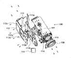
Fig. 3 is the perspective view of surveillance camera internal structure body embodiment illustrated in fig. 1 of the present invention;
Fig. 4 A and 4B are the perspective views of surveillance camera internal structure body embodiment illustrated in fig. 1 of the present invention; And
Fig. 5 A and 5B are the perspective views of surveillance camera casing embodiment illustrated in fig. 1 of the present invention.
Embodiment
The following describes the first embodiment of the present invention.Fig. 1 and 2 is respectively the view from the being seen surveillance camera 100 of left oblique upper and right tiltedly below.Make an explanation below with reference to Fig. 1 and 2.In Fig. 1 and 2, the casing that Reference numeral 101 expressions are made by metallic plate; 103,108 and 107 represent panel U, the panel F and the panel B that make by die-casting material respectively; Panel L and panel R that 105 and 106 expressions are made by metallic plate.These members have constituted the appearance surfaces as housing of surveillance camera 100.
Casing 101 roughly has the U font.Tripod screw member 102a and 102b are installed to the upper and lower of casing 101.After tripod screw member 102a was mounted, panel U 103 was installed to the top of casing 101.In this case, the hole 103a of the threaded portion of tripod screw member 102a from panel U 103 exposes.Because tripod screw member 102a is exposed, tripod etc. can be installed to this part.The material of panel U 103 comprises elastomer, and the surface of panel U 103 has been stamped and has numerous hole, forms the circle concentric with hole 103a.Like this, panel U 103 has great friction coefficient with respect to the tripod installation surface and therefore is difficult to unclamp from it.
Panel F 108 is installed to the front surface of casing 101.Lens unit 110 (will be described hereinafter) enters the hole 108a among the panel F 108, to expose its barrel.The part of tripod screw member 102b enters the hole 108b among the panel F 108, strengthens the installation strength of tripod screw member 102b in the mode identical with the hole 103a of panel U 103.In addition, panel B 107 is placed on the rear surface of casing 101.Panel B 107 has hole 107a etc., can be by it to exposing outside connector.
After above-mentioned member was installed to casing 101, left panel L 105 and right panel R 106 utilized threaded portion 101a of casing 101 etc. to be installed to casing 101.Because casing 101 closely contacts with panel R 106 with panel L 105 by threaded portion 101a etc., casing 101 is with panel L 105 and panel R 106 mutual hot links and be electrically connected.Because casing 101, panel L 105 and panel R 106 as metal material constitute the internal structure body, surveillance camera 100 has fabulous fastness.
Describe this internal structure body below in detail.Fig. 3 is that the outward appearance member is removed the perspective view with the surveillance camera 100 that shows the internal structure body.With reference to figure 3, Reference numeral 111 expression main substrates.Electronic component such as CPU 111b, expose appearance surfaces and be installed on the main substrate 111 with aerial lug 111a of being connected with the outside etc.Main substrate 111 can be installed to have heat sinking function, on the barricade 112 of electro-magnetic screen function and heat conduction function.When main substrate 111 is installed to barricade 112, the barricade 112 main CPU 111b sides that cover main substrate 111.The heat that barricade 112 has the 112c of GND portion of the GND figure (not shown) of desiring to be electrically connected to main substrate 111, produce CPU 111b be transmitted to barricade 112 the 112d of the portion of being heated, temporary fixed main substrate 111 pawl 112a and will be by hot link, be electrically connected to the main body connecting portion 112b of casing 101.
The GND figure of main substrate 111 contacts with barricade 112 by the 112c of GND portion, and main substrate 111 is arranged on identical current potential with barricade 112, so that the capability of electromagnetic shielding of 112 pairs of main substrates 111 of barricade strengthens.Because barricade 112 is fixed to casing 101 by main body connecting portion 112b, casing 101, barricade 112 and main substrate 111 have identical GND current potential.
When main substrate 111 was installed to barricade 112, the portion 112d of being heated was positioned at the CPU111b top, to pass through heat radiation rubber 115 and CPU 111b hot link, to be heated from CPU111b.Barricade 112 is made by the aluminium with high heat conductance.Barricade 112 is conducted to whole barricade 112 substantially equably from the heat that CPU 111b receives, to dispel the heat to atmosphere from the whole surface of barricade 112 by radiation and convection current.As mentioned above, because casing 101 and barricade 112 contact with each other by main body connecting portion 112b, they also can give casing 101 with heat conduction.
Pawl 112a is used for main substrate 111 is temporarily anchored to barricade 112.When main substrate 111 and barricade 112 desires formation unit, main substrate 111 is moved toward the precalculated position of barricade 112.Be formed on the projection (not shown) distortion on a left side and the right pawl 112a, so that main substrate 111 is crossed over a left side and right pawl 112a, and left and right pawl 112a is opened to both sides.When the distortion of the projection (not shown) of pawl 112a when main substrate 111 is crossed over left and right pawl 112a fully, fitting operation is finished with " card clatter " action sound.When main substrate 111 and barricade 112 formed the unit as mentioned above, barricade 112 was fixed to casing 101 at main body connecting portion 112b place.As a result, main substrate 111 is placed in the pre-position of casing 101.
The inside of casing 101 will be described with reference to the decomposition diagram of figure 4A and 4B.With reference to figure 4A and 4B, Reference numeral 113 expression lens brackets.Lens unit 110 desires to be placed in the top of lens bracket 113.When lens bracket 113 was installed to casing 101, lens unit 110 was placed in the pre-position of casing 101.Lens bracket 113 has heat-conducting part 113a, and closely contacts with the radiating part 110a of lens unit 110 by heat radiation rubber.When lens unit 110 is installed to casing 101, the surface with the surface opposite that contacts with heat radiation rubber in heat-conducting part 113a closely contacts with the 101b of the portion of being heated of casing 101, so that heat-conducting part 113a directly contacts with casing 101, arrive casing 101 heat is loose by heat conduction.
At last, will be with reference to figure 5A and 5B explanation outward appearance.Fig. 5 A is from the being seen view of oblique upper, and Fig. 5 B is from the being seen view in oblique below.Shown in Fig. 5 A and 5B, the tripod screw member 102a and the 102b of surveillance camera 100 expose in the upper and lower, so that surveillance camera 100 can fix in every way, for example, by from overhung or by fixing from supported underneath.Curved surface 108c is formed on the bottom of surveillance camera 100 front surfaces, so that for example when surveillance camera 100 is placed in dome, the bight of surveillance camera 100 can not contact with the inwall of dome.When from the front or below when seeing curved surface 108c, as mentioned above, can be identified from the light of LED guiding piece 114 guiding.
The invention is not restricted to the foregoing description, and can make various changes and modification within the spirit and scope of the present invention.So,, made following claim for informing public's protection scope of the present invention.
Claims (6)
1. surveillance camera, described surveillance camera is included in the metal body in the housing, and has the screw thread installation portion in the upper and lower of described metal body, wherein, described housing is by the upper surface that covers described metal body respectively, rear surface, front surface and lower surface, the housing member on left surface and right at least surface constitutes at least, it is characterized in that described surveillance camera also comprises circuit board and covers the metal framework of described circuit board; Heat conduction member is attached to the predetermined portions of described metal framework, and described circuit board and metal framework are engaged by the claw that is formed on the described metal framework.
2. video camera according to claim 1, it is characterized in that, when described circuit board and metal framework were engaged, the described heat conduction member on the described metal framework was placed on the heat-generating electronic elements of described circuit board, closely to contact with described heat-generating electronic elements.
3. video camera according to claim 2, it is characterized in that, when described circuit board and metal framework were engaged, the earthed circuit figure on described metal framework top closely contacted with earthed circuit figure on being formed on described circuit board, and then closely contacted with connector on the described circuit board.
4. according to each described video camera among the claim 1-3, it is characterized in that the described metal framework that engages with described circuit board is installed on the described metal body, to form the box structure body.
5. video camera according to claim 4, it is characterized in that, the heat of the electronic component on the described circuit board is by the metal framework conduction of described heat conduction member to described joint, and then to the described metal body conduction that is connected to described metal framework, with with heat from described metal body to described housing conduction mounted thereto, thereby heat is distributed to described outside.
6. video camera according to claim 5 is characterized in that described heat conduction member comprises heat conductive rubber.
Applications Claiming Priority (2)
| Application Number | Priority Date | Filing Date | Title |
|---|---|---|---|
| JP2004327379 | 2004-11-11 | ||
| JP2004327379A JP4448009B2 (en) | 2004-11-11 | 2004-11-11 | Surveillance camera |
Publications (2)
| Publication Number | Publication Date |
|---|---|
| CN1774042A CN1774042A (en) | 2006-05-17 |
| CN100394771C true CN100394771C (en) | 2008-06-11 |
Family
ID=36315910
Family Applications (1)
| Application Number | Title | Priority Date | Filing Date |
|---|---|---|---|
| CNB2005101159694A Expired - Fee Related CN100394771C (en) | 2004-11-11 | 2005-11-11 | Monitoring camera |
Country Status (5)
| Country | Link |
|---|---|
| US (1) | US7583314B2 (en) |
| JP (1) | JP4448009B2 (en) |
| KR (1) | KR100820846B1 (en) |
| CN (1) | CN100394771C (en) |
| TW (1) | TWI277342B (en) |
Families Citing this family (16)
| Publication number | Priority date | Publication date | Assignee | Title |
|---|---|---|---|---|
| JP4869181B2 (en) * | 2007-08-27 | 2012-02-08 | 三洋電機株式会社 | Portable device with heat dissipation structure |
| US8245670B2 (en) * | 2008-03-13 | 2012-08-21 | Schmitt David W | High temperature adjustable sensor housing system apparatus |
| JP4597225B2 (en) * | 2008-06-26 | 2010-12-15 | 株式会社日立製作所 | Surveillance video camera |
| ES2370560T3 (en) * | 2008-11-06 | 2011-12-20 | Axis Ab | ACCOMMODATION FOR ELECTRONIC DEVICE. |
| JP5188412B2 (en) * | 2009-01-29 | 2013-04-24 | キヤノン株式会社 | Imaging apparatus and electronic apparatus |
| US9661235B2 (en) | 2012-04-13 | 2017-05-23 | Blackmagic Design Pty Ltd. | Camera having a separate image capture module and a method of assembling the camera |
| JP6000752B2 (en) | 2012-08-27 | 2016-10-05 | キヤノン株式会社 | Imaging device |
| JP6000751B2 (en) * | 2012-08-27 | 2016-10-05 | キヤノン株式会社 | Imaging device |
| JP6080510B2 (en) * | 2012-11-09 | 2017-02-15 | キヤノン株式会社 | Heat dissipation component, imaging device, and electronic device |
| KR101387460B1 (en) | 2012-12-26 | 2014-04-21 | 티.비.티. 주식회사 | Camera and camera controller |
| DE102014008452A1 (en) * | 2014-06-05 | 2015-12-17 | Ids Imaging Development Systems Gmbh | Camera with a camera body |
| KR102138332B1 (en) * | 2014-06-09 | 2020-07-27 | 한화테크윈 주식회사 | Security camera |
| CN106163209B (en) * | 2015-03-25 | 2019-04-16 | 小米科技有限责任公司 | Radiating subassembly and electronic equipment |
| JP2017044795A (en) * | 2015-08-25 | 2017-03-02 | オリンパス株式会社 | Image-capturing device |
| JP2019087776A (en) * | 2017-11-01 | 2019-06-06 | 株式会社ザクティ | Stationary camera device |
| JP2022150986A (en) * | 2021-03-26 | 2022-10-07 | ミツミ電機株式会社 | camera |
Citations (7)
| Publication number | Priority date | Publication date | Assignee | Title |
|---|---|---|---|---|
| JPH089206A (en) * | 1994-06-15 | 1996-01-12 | Sanyo Electric Co Ltd | Monitor video camera |
| CN2247400Y (en) * | 1995-12-29 | 1997-02-12 | 余双仑 | Moving picture camera with sealing shock-proof structure |
| JPH09214819A (en) * | 1996-01-30 | 1997-08-15 | Sony Corp | Image pickup device |
| JPH11249214A (en) * | 1998-03-05 | 1999-09-17 | Sony Corp | Support structure of structure body and circuit board |
| JP2001111876A (en) * | 1999-10-06 | 2001-04-20 | Fuji Photo Film Co Ltd | Electroinc still camera with built-in printer |
| US20040125560A1 (en) * | 2002-12-26 | 2004-07-01 | Akihiro Gotou | Electronic device |
| CN1542538A (en) * | 2003-04-28 | 2004-11-03 | ������������ʽ���� | Image-taking apparatus |
Family Cites Families (21)
| Publication number | Priority date | Publication date | Assignee | Title |
|---|---|---|---|---|
| DE3144275C1 (en) * | 1981-11-07 | 1983-04-14 | Grundig E.M.V. Elektro-Mechanische Versuchsanstalt Max Grundig & Co KG, 8510 Fürth | "Compact television camera for indoor or outdoor use" |
| US4652930A (en) * | 1984-11-19 | 1987-03-24 | Rca Corporation | Television camera structure |
| JP3196287B2 (en) | 1992-01-24 | 2001-08-06 | ソニー株式会社 | Video camera |
| JPH07162726A (en) * | 1993-12-07 | 1995-06-23 | Sony Corp | Rear panel |
| JPH0851291A (en) * | 1994-08-05 | 1996-02-20 | Sony Corp | Electronic equipment |
| JPH08102880A (en) | 1994-10-03 | 1996-04-16 | Elmo Co Ltd | Monitoring video camera |
| US5999406A (en) * | 1995-02-23 | 1999-12-07 | Avid Technology, Inc. | Dockable electronic equipment container |
| JPH09163207A (en) * | 1995-12-08 | 1997-06-20 | Sony Corp | Recording and reproducing device |
| US5864365A (en) * | 1996-01-26 | 1999-01-26 | Kaman Sciences Corporation | Environmentally controlled camera housing assembly |
| US6392704B1 (en) * | 1997-11-07 | 2002-05-21 | Esco Electronics Corporation | Compact video processing system for remote sensing applications |
| JP3363772B2 (en) * | 1998-02-25 | 2003-01-08 | 三洋電機株式会社 | Surveillance camera device |
| US6628338B1 (en) * | 1998-07-08 | 2003-09-30 | Elbex Video Ltd. | Direct drive electric motor apparatus incorporating slip ring assembly |
| US6320748B1 (en) * | 2000-03-17 | 2001-11-20 | Celestica International Inc. | Power heatsink for a circuit board |
| US6894724B2 (en) * | 2000-11-03 | 2005-05-17 | Pelco | Water resistant surveillance camera housing and scanner with magnetic positioning stops |
| JP2002369184A (en) * | 2001-06-05 | 2002-12-20 | Canon Inc | Image processor, image pickup device, control method of image processor, control method of image pickup device, and recording medium |
| JP4083521B2 (en) * | 2001-10-29 | 2008-04-30 | オリンパス株式会社 | Imaging device |
| JP3968503B2 (en) * | 2001-12-17 | 2007-08-29 | ソニー株式会社 | Imaging device |
| JP2003244495A (en) * | 2002-02-14 | 2003-08-29 | Canon Inc | Housing apparatus |
| JP2004032459A (en) * | 2002-06-27 | 2004-01-29 | Hitachi Ltd | Monitoring system, and controller and monitoring terminal used both therefor |
| USD509843S1 (en) * | 2004-05-27 | 2005-09-20 | Canon Kabushiki Kaisha | Network camera |
| JP4438737B2 (en) * | 2005-11-14 | 2010-03-24 | 株式会社日立製作所 | Portable electronic devices |
-
2004
- 2004-11-11 JP JP2004327379A patent/JP4448009B2/en not_active Expired - Fee Related
-
2005
- 2005-10-21 TW TW094136918A patent/TWI277342B/en not_active IP Right Cessation
- 2005-10-27 US US11/260,698 patent/US7583314B2/en not_active Expired - Fee Related
- 2005-11-11 CN CNB2005101159694A patent/CN100394771C/en not_active Expired - Fee Related
- 2005-11-11 KR KR1020050107904A patent/KR100820846B1/en active IP Right Grant
Patent Citations (7)
| Publication number | Priority date | Publication date | Assignee | Title |
|---|---|---|---|---|
| JPH089206A (en) * | 1994-06-15 | 1996-01-12 | Sanyo Electric Co Ltd | Monitor video camera |
| CN2247400Y (en) * | 1995-12-29 | 1997-02-12 | 余双仑 | Moving picture camera with sealing shock-proof structure |
| JPH09214819A (en) * | 1996-01-30 | 1997-08-15 | Sony Corp | Image pickup device |
| JPH11249214A (en) * | 1998-03-05 | 1999-09-17 | Sony Corp | Support structure of structure body and circuit board |
| JP2001111876A (en) * | 1999-10-06 | 2001-04-20 | Fuji Photo Film Co Ltd | Electroinc still camera with built-in printer |
| US20040125560A1 (en) * | 2002-12-26 | 2004-07-01 | Akihiro Gotou | Electronic device |
| CN1542538A (en) * | 2003-04-28 | 2004-11-03 | ������������ʽ���� | Image-taking apparatus |
Also Published As
| Publication number | Publication date |
|---|---|
| KR20060052620A (en) | 2006-05-19 |
| KR100820846B1 (en) | 2008-04-11 |
| CN1774042A (en) | 2006-05-17 |
| JP2006140673A (en) | 2006-06-01 |
| US7583314B2 (en) | 2009-09-01 |
| TWI277342B (en) | 2007-03-21 |
| TW200627935A (en) | 2006-08-01 |
| US20060098117A1 (en) | 2006-05-11 |
| JP4448009B2 (en) | 2010-04-07 |
Similar Documents
| Publication | Publication Date | Title |
|---|---|---|
| CN100394771C (en) | Monitoring camera | |
| US11231170B2 (en) | LED luminaire having enhanced thermal management | |
| US20070268667A1 (en) | Air-cooling system configuration for touch screen | |
| WO2006105731A1 (en) | Light emitting array apparatus and method of manufacture | |
| CN116325772A (en) | Secure camera with angled cable attachment to achieve increased downward viewing angle | |
| KR100874037B1 (en) | Infrared camera for cctv | |
| US20050094407A1 (en) | Mid-sized traffic signal light chassis for modular intelligent traffic light system | |
| JP2006140673A5 (en) | ||
| CN112702480B (en) | Camera and communication equipment | |
| JP3636331B2 (en) | Built-in camera street light | |
| TWI582516B (en) | Light source assembly and camera device having light source assembly | |
| US20140002784A1 (en) | Heat dissipation construction for indoor-outdoor lcd sign board | |
| KR101723146B1 (en) | Internet protocol camera module integrated led luminaire | |
| JP5253262B2 (en) | Electronic equipment unit | |
| CN212255974U (en) | Photographic lamp | |
| JP2023005195A (en) | Lighting device | |
| CN211630268U (en) | Cloth control ball | |
| KR200368749Y1 (en) | Focus regulation equipment of cctv camera | |
| KR100594640B1 (en) | Dvr system | |
| JP2024018629A (en) | lighting equipment | |
| KR200374349Y1 (en) | Dvr system | |
| CN104965383A (en) | Projection device | |
| CN110730292A (en) | Industrial camera shell convenient to assemble and disassemble | |
| CN117280275A (en) | Display unit and display device | |
| JPH03178197A (en) | Casing structure for electronic equipment |
Legal Events
| Date | Code | Title | Description |
|---|---|---|---|
| C06 | Publication | ||
| PB01 | Publication | ||
| C10 | Entry into substantive examination | ||
| SE01 | Entry into force of request for substantive examination | ||
| C14 | Grant of patent or utility model | ||
| GR01 | Patent grant | ||
| CF01 | Termination of patent right due to non-payment of annual fee |
Granted publication date: 20080611 Termination date: 20201111 |
|
| CF01 | Termination of patent right due to non-payment of annual fee |