CN100387771C - Steam iron with multifunction dripper - Google Patents
Steam iron with multifunction dripper Download PDFInfo
- Publication number
- CN100387771C CN100387771C CNB038240262A CN03824026A CN100387771C CN 100387771 C CN100387771 C CN 100387771C CN B038240262 A CNB038240262 A CN B038240262A CN 03824026 A CN03824026 A CN 03824026A CN 100387771 C CN100387771 C CN 100387771C
- Authority
- CN
- China
- Prior art keywords
- drip
- flatiron
- water
- lever
- valve
- Prior art date
- Legal status (The legal status is an assumption and is not a legal conclusion. Google has not performed a legal analysis and makes no representation as to the accuracy of the status listed.)
- Expired - Fee Related
Links
Images


Classifications
-
- D—TEXTILES; PAPER
- D06—TREATMENT OF TEXTILES OR THE LIKE; LAUNDERING; FLEXIBLE MATERIALS NOT OTHERWISE PROVIDED FOR
- D06F—LAUNDERING, DRYING, IRONING, PRESSING OR FOLDING TEXTILE ARTICLES
- D06F75/00—Hand irons
- D06F75/08—Hand irons internally heated by electricity
- D06F75/10—Hand irons internally heated by electricity with means for supplying steam to the article being ironed
- D06F75/14—Hand irons internally heated by electricity with means for supplying steam to the article being ironed the steam being produced from water in a reservoir carried by the iron
- D06F75/18—Hand irons internally heated by electricity with means for supplying steam to the article being ironed the steam being produced from water in a reservoir carried by the iron the water being fed slowly, e.g. drop by drop, from the reservoir to a steam generator
Abstract
The invention concerns a steam iron comprising a water reservoir (1), a hydraulic circuit (3) connecting the reservoir (1) to an electrically heated vaporization chamber (23), the circuit including in series an anti-drip valve (4), and an adjustable drip element (5) capable, in a self-cleaning position, of opening allowing a free passageway and supplying water to said chamber. The invention is characterized in that the drip element comprises means for opening or maintaining open the anti-drip valve (4), when it is in the self-cleaning position.
Description
Technical field
[01] the present invention relates to steam generating iron, the water that one of them water receiver provides is almost vaporization simultaneously in a vaporization chamber, controls the flow that water flows to vaporization chamber from water receiver by a drip.
Background technology
[02] improved flatiron also comprises an anti-drip device, and flowing of the water that this anti-drip device prevention will be evaporated when vaporization chamber is warm inadequately avoided water is sprayed on the flatiron line.A kind of simple thermostat that satisfies this function is constituted by the bimetal leaf of steam chamber heating by one, this bimetal leaf is opened an anti-drip trap of connecting with drip.
[03] improved flatiron comprises the self-cleaning device that is used to clean vaporization chamber inside in addition.This self-cleaning device is made of a bigger opening that is located at the water receiver inner bottom part, can promptly be emptied to described water receiver in the vaporization chamber by this opening, therefore produces the injection stream of the water and the steam of a cleaning flatiron.Therefore although steaming chamber sharply cools off, and anti-drip trap cuts out, and water can continue to flow to steam chamber from water receiver.
[04] patent FR 2589492 has described a kind of flatiron, and this flatiron comprises that a control water flows into the drip of the flow of vaporization chamber.Drip is connected with an anti-drip trap, and this anti-drip trap is installed on the lever, and this lever is driven swing by a thermally sensitive bimetal leaf.The anti-drip device of system closing waterpower pipeline when but this flatiron does not comprise self-cleaning device and vaporization chamber cooling.
[05] patent FR 2769925 has described a kind of flatiron with self-cleaning function, and this self-cleaning function is made of a self-cleaning valve, and self-cleaning valve is by an encirclement drip and the elastomeric material bell-jar of drip short circuit is formed.But flatiron does not comprise anti-drip device.
[06] patent DE29720259 has described a kind of flatiron, wherein obtain drip function and cleaning function by same controller, this controller is acting in the first of its stroke on the needle valve of drip, produces self-cleaning action on a second portion, and flatiron is simplified.But this flatiron does not comprise anti-drip device.
[07] patent WO9945190 has described a kind of flatiron that comprises a drip, an anti-drip device and a self-cleaning function.But in order to realize all these functions, this flatiron comprises two controllers and a valve that makes the anti-drip device short circuit.
[08] patent FR2821368 has described a kind of flatiron that comprises a drip, an anti-drip device and a self-cleaning function.But this function realizes that by the parts of a multilayer folding part these parts have an end that forms valve, and therefore an additional packing ring must seal.
Summary of the invention
[09] target of the present invention is an improved flatiron, and this flatiron comprises a drip, an anti-drip device and a self-cleaning device, and the use of these devices is very simple, and this flatiron comprises minimum element, makes the design economy, reliable of flatiron.
[10] purpose of the present invention reaches by a steam generating iron, this flatiron comprises a water receiver, a waterpower pipeline that connects a water receiver and an electrical heating vaporization chamber, the series connection of waterpower pipeline comprises an anti-drip trap and an adjustable drip, drip can be opened a self-cleaning position, reserve a clear passage of water being guided into described vaporization chamber, this flatiron is characterised in that drip comprises the device that makes antidrip lid open or keep opening when drip is in self-cleaning position.
[11] because these devices do not need a valve that makes the anti-drip device short circuit, so the minimizing of the quantity of the element of water, thereby reliability increases.
[12] drip preferably can be regulated with a controller with two stroke parts, and first can limit and regulate the flow of evaporation water, and second portion produces the clear passage of water being guided into described vaporization chamber.
[13] thus the use of flatiron be easy to, and have less controller.
[14] open or keep the open device of anti-drip trap to comprise the lever that to open anti-drip trap by its a wherein end, and this lever is driven by a moving element of drip by the other end.
[15] recommend in the version at one, the bar of drip comprises one at the shotpin of the second stroke partial action on lever.
[16] in another version, the bar of drip is surrounded by a module, and this module comprises a stopper that is used to act on the lever, and module is opened a big passage for water in second stroke part.
[17] anti-drip device preferably includes a thermostat that is made of a bimetal leaf, and bimetal leaf bears the vaporization chamber temperature, and is enough to open when well being vaporized valve when the temperature of vaporization chamber.
[18] anti-drip device preferably includes one and valve is abutted on the bimetal leaf or at the flexible member of closed position, lever is resisted this flexible member.
[19] therefore, lever does not apply any stress on bimetal leaf, and bimetal leaf does not bear the power that makes valve open when self-cleaning beginning.
Description of drawings
[20] can understand the present invention better by following Example and accompanying drawing.
[21] Fig. 1 is a partial longitudinal section that meets the flatiron of first version of the present invention, and flatiron is in cooling, inactive state.
[22] Fig. 2 is a details of Fig. 1 flatiron, and flatiron is hot, and normally evaporation.
[23] Fig. 3 is a details of Fig. 1 flatiron, and flatiron is in self-cleaning position.
[24] Fig. 4 is a partial longitudinal section that meets the flatiron of second version of the present invention, and motion is in cooling, inactive state.
[25] Fig. 5 is a details of Fig. 4 flatiron, and flatiron is hot, and normally evaporation.
[26] Fig. 6 is a details of Fig. 4 flatiron, and flatiron is in self-cleaning position.
The specific embodiment
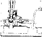
[27] in the first version of the present invention that Fig. 1-3 sees, flatiron comprises the water receiver 1 of the water that will evaporate, a base plate 2, and base plate 2 has a calandria 21 under the effect of an electrical heating elements 22.The vaporization chamber 23 that cover plate 231 of a usefulness is closed is located in the calandria 21.Some pipelines connect vaporization chamber 23 and steam (vapor) outlet 24.
[28] water receiver 1 is connected with vaporization chamber 23 by a waterpower pipeline 3, and 3 series connection of waterpower pipeline comprise an anti-drip trap 4 and the drip 5 with an axle 41.Valve 4 is generally got back to the closed position by the elasticity of a film 42, and as shown in Figure 1, film 42 constitutes a wall of pipeline 3.
[29] antidrip thermostats are made of a bimetal leaf 6, and a wherein end of bimetal leaf 6 is connected with the wall of vaporization chamber 23 by a heat conduction boss 61.The other end of bimetal leaf 6 can act on the bar of valve 4, the opposing film 42 effect, with convenient flatiron be heat the time open valve 4, as shown in Figure 2.
[30] drip 5 comprises a controller 51, and this controller 51 can move a bar 52 that has a shotpin 53 along its axle.The end of bar 52 is gate throttles 54, and the gate throttle part is provided with the groove 541 of a variable cross section.Gate throttle along sliding on the lip limit 32 of an outlet of its pipeline 3 of axle in vaporization chamber, can be controlled the flow of water, as depicted in figs. 1 and 2 in the first of controller stroke like this.Bar 52 has a constriction 55 at gate throttle more than 54, when gate throttle when second stroke part is exposed on lip limit 32, this constriction is that water mobile reserved a major path.
[31] controller 51 is buttons that an end has a cam 511.Rotary knob obtains regulating the first stroke part of the controller of discharge.In this motion, cam 511 catch bars 52, the effect of a spring 521 of opposing, it is in place that bar 52 is stablized, and as shown in Figure 1, 2, gate throttle 54 keeps contacting with lip limit 32.
[32] second portion of controller stroke presses the button 51 and obtains by the axle along button 51, as shown in Figure 3.Then gate throttle is deviate from from lip limit 32, and the constriction 55 of bar 52 is corresponding with lip limit 32.The lever 7 that shotpin 53 promotions are simultaneously swung on the rib ridge of a flange 71.The other end of lever 7 is enclosed within on the axle 41 of valve 4, and therefore regardless of the state of bimetal leaf 6, it is open that valve 4 all keeps.
[33] in order to use flatiron, the user is full of water receiver 1.Cold bimetal leaf 6 is in the position of Fig. 1, and valve 4 is closed by the effect of film 42.The user can regulate the flow of drip in advance by the value that control button 51 rotations are needed, so the steam regulation flow.The lip limit 32 of drip port is corresponding with the part of gate throttle 54, and the groove 541 of this part has a cross section that adapts to required flow.When flatiron is heated to when being enough to make the good vaporization of water generates, bimetal leaf 6 skews, and promote the axle 41 of valve 4, so that open valve 4, as shown in Figure 2.Then water can pass the channel flow of valve 4, pipeline 3 and drip 5 from water receiver 1, by the cross section of lip limit 32 control channels.
[34] when user decision her flatiron is carried out when self-cleaning, user's antagonistic spring 521 is pressed control button 51.Gate throttle 54 is deviate from from lip limit 32, and then lip limit 32 is corresponding with constriction 55, discharges a big passage therefore for the water from water receiver 1.Simultaneously, the shotpin 53 of drip bar abuts on the end of lever 7, and the other end of lever is resisted flexibly lifting of film 42 or kept lifting described valve 4.Flatiron cools off rapidly, and the water of part vaporization causes the cleaning of flatiron in the vaporization chamber 23, and bimetal leaf separates from axle 41.But this axle 41 is kept by lever 7, and valve 4 keeps opening in whole cleaning course, can finish the cleaning of flatiron so well.
[35] in case the user loosens button 51, button 51 just retreats under the effect of spring 521.Shotpin 53 is driven does identical motion, and lever 7 loosens valve 4, and valve 4 is closed, and becomes enough hot again up to flatiron, so that make bimetal leaf 6 open valve 4, therefore can vaporize normally again.
[36] in second version of the present invention of seeing in Fig. 4-6, flatiron comprises a water receiver of wanting evaporation water 1, a base plate 2, and base plate 2 has a calandria 21 under the effect of an electrical heating elements 22.A vaporization chamber 23 of being closed by a cover plate 231 is located in the calandria 21.Some pipelines connect vaporization chamber 23 and steam (vapor) outlet 24.
[37] water receiver 1 is connected with vaporization chamber 23 by a waterpower pipeline 3, and 3 series connection of waterpower pipeline comprise an anti-drip trap 4 and a drip 5, and anti-drip trap 4 has an axle 41, and a lower end of axle 41 has a convex shoulder 411.A spring 42 makes anti-drip trap 4 generally get back to the closed position, as shown in Figure 4.
[38] constant temperature anti-drip devices are made of a bimetal leaf 6, and a wherein end of bimetal leaf 6 is connected with the wall of vaporization chamber 23 by a heat conduction boss 61.The other end of bimetal leaf 6 comprises a fork, and this fork can abut on the convex shoulder 411, thereby antagonistic spring 42 acts on the bar of valve 4, so as described flatiron be heat time marquis open described valve, as shown in Figure 5.
[39] drip 5 comprises a controller 51 that has a cam 511, controller 51 comprise one on first stroke part the part that otch is arranged and the part smooth and big slope on second portion at stroke.Cam can move a bar 52 along its axle, the effect of a spring 521 of opposing.The end of bar 52 is needle valves of the channel cross-section of an eyelet 54 of a control, and eyelet 54 is located in the module 56 of an encirclement needle valve, and module 56 can hang on the bar 52, and lifts, so that discharge a major path that makes water pass drip.In the first of control stroke, bar 52 moves needle valve, and then module is closed major path, can control the flow of water like this, shown in Fig. 4,5.
[40] at the second portion of stroke, as long as the user maintains controller, bar 52 just lifts module 56.In addition, module 56 has a convex shoulder 53, and convex shoulder 53 lifts the end of a lever 7 of swinging on the rib ridge of a flange 71.The other end of lever 7 is supported on axle 41 the end of valve 4, and therefore as seeing in Fig. 6, regardless of the state of bimetal leaf 6, valve 4 all keeps opening.
[41] water receiver 1 is made up of two elements, goes up element and a following element for one.For the ease of the assembling of drip, on lever 7 and module 56 are assembled in before water receiver is closed in advance on the element.For this reason, lever 7 keeps installing by a spring 73 and a screw of tightening a little on last element 72.In order to close water receiver, spring 73 is compressed, and makes lever 7 keep abutting on the rib ridge of the flange 71 that belongs to following element.
[42] in order to use flatiron, the user fills water receiver 1.Cold bimetal leaf 6 is in the position of Fig. 4, and valve 4 is closed by the effect of spring 42.The discharge that the user can regulate drip in advance by the value that control button 51 rotation is needed, so the flow of steam regulation.The needle valve of drip forms a channel cross-section that adapts to required discharge.When flatiron is heated to when being enough to make water generates well to be vaporized, bimetal leaf 6 skews, and the axle 41 of pulling valve 4 are so that open valve 4, as shown in Figure 5.Therefore water can flow from water receiver 2, passes valve 4, pipeline 3 and drip channel 5, and the cross section of drip channel 5 is controlled by needle valve.Then the user can normally press.
[43] when user decision her flatiron is carried out when self-cleaning, button 51 is pushed to its stroke end.Module is lifted, for the water from water receiver 1 discharges a big passage.Simultaneously, the convex shoulder 53 of module is supported on the end of lever 7, and the other end antagonistic spring 42 of lever 7 lifts valve 4 or keeps lifting.Flatiron cools off rapidly, and the water of part vaporization causes the cleaning of flatiron in the vaporization chamber 23, and bimetal leaf separates with spools 41 convex shoulder 411.But this axle is kept by lever 7, and it is open that valve 4 keeps in the process of whole cleaning operation, can finish the self-cleaning of flatiron well like this.
[44] in case the user loosens control button 51, control button 51 retreats under the effect of spring 521, causes module to be closed.Convex shoulder 53 is driven does identical motion, lever 7 relief valve 4, and valve 4 is closed, and reheating up to flatiron is enough to make bimetal leaf 6 to open valve 4, therefore can vaporize normally again.
Claims (6)
1. steam iron, described flatiron comprises: a water receiver (1); One waterpower pipeline (3), its described water receiver (1) is connected to an electrical heating vaporization chamber (23), and described pipeline (3) in series comprises an anti-drip trap (4); With an adjustable drip (5), described drip (5) can be opened in a self-cleaning position, thereby reserves a clear passage and water is guided into described vaporization chamber (23);
Described flatiron is characterised in that described drip (5) comprises the device of opening described anti-drip trap (4) or described anti-drip trap (4) is stayed open when described drip being positioned at self-cleaning position.
2. flatiron as claimed in claim 1, it is characterized in that, described drip (5) can be regulated by a controller, described controller has a stroke divided into two parts, described first stroke can limit and regulate the flow of vaporize water, and described second portion stroke produces clear passage and water is guided into described vaporization chamber (23).
3. as each described flatiron in the above-mentioned claim, it is characterized in that, the described device that is used to open described anti-drip trap or makes described anti-drip trap keep opening comprises a lever (7), described lever (7) can be opened described anti-drip trap (4) by its a wherein end, and is driven by a moving element of drip (5) by the other end.
4. flatiron as claimed in claim 3 is characterized in that, the bar (52) of described drip (5) comprises that one can act on the shotpin (53) on the described lever (7).
5. flatiron as claimed in claim 3 is characterized in that, the bar (52) of described drip (5) is surrounded by a module (56), and described module (56) is opened a big passage in the second portion feedwater of stroke; Described module (56) comprises that one can act on the stopper (53) on the described lever (7).
6. as each described flatiron in the above-mentioned claim, it is characterized in that, described anti-drip device comprises a flexible member (42), described flexible member (42) returns described valve (4), abut in a bimetal leaf (6) and go up or get back to a closed position, and described lever (7) is resisted this flexible member (42).
Applications Claiming Priority (2)
| Application Number | Priority Date | Filing Date | Title |
|---|---|---|---|
| FR0212449A FR2845400B1 (en) | 2002-10-08 | 2002-10-08 | IRON WITH MULTIPURPOSE DRIP |
| FR02/12449 | 2002-10-08 |
Publications (2)
| Publication Number | Publication Date |
|---|---|
| CN1688759A CN1688759A (en) | 2005-10-26 |
| CN100387771C true CN100387771C (en) | 2008-05-14 |
Family
ID=32011481
Family Applications (1)
| Application Number | Title | Priority Date | Filing Date |
|---|---|---|---|
| CNB038240262A Expired - Fee Related CN100387771C (en) | 2002-10-08 | 2003-09-30 | Steam iron with multifunction dripper |
Country Status (12)
| Country | Link |
|---|---|
| US (1) | US7181874B2 (en) |
| EP (1) | EP1554424B1 (en) |
| CN (1) | CN100387771C (en) |
| AT (1) | ATE361389T1 (en) |
| AU (1) | AU2003265056A1 (en) |
| CA (1) | CA2501553C (en) |
| DE (1) | DE60313645T8 (en) |
| FR (1) | FR2845400B1 (en) |
| HK (1) | HK1079254A1 (en) |
| MX (1) | MXPA05003754A (en) |
| RU (1) | RU2324779C2 (en) |
| WO (1) | WO2004033786A1 (en) |
Families Citing this family (9)
| Publication number | Priority date | Publication date | Assignee | Title |
|---|---|---|---|---|
| ES2330698B1 (en) * | 2006-10-24 | 2010-09-21 | Bsh Krainel, S.A. | STEAM IRON. |
| ES2360994B1 (en) * | 2008-08-22 | 2012-04-19 | Bsh Electrodomésticos España, S.A. | STEAM IRON. |
| ES2385077B1 (en) * | 2008-12-23 | 2013-06-14 | Bsh Electrodomésticos España, S.A. | STEAM IRONING DEVICE. |
| EP2213783A1 (en) * | 2009-01-28 | 2010-08-04 | Koninklijke Philips Electronics N.V. | Steam iron |
| WO2011076546A1 (en) * | 2009-12-22 | 2011-06-30 | BSH Bosch und Siemens Hausgeräte GmbH | Electrical steam iron and valve |
| FR2974821B1 (en) * | 2011-05-06 | 2013-04-19 | Seb Sa | IRON CONTAINING A STEAM CONTROL BUTTON |
| CN106661818B (en) * | 2014-08-26 | 2019-06-25 | 皇家飞利浦有限公司 | Handheld type steam equipment |
| FR3065210B1 (en) * | 2017-04-12 | 2019-07-05 | Seb S.A. | HOUSEHOLD APPLIANCE COMPRISING MEANS FOR HEATING WATER AND A DEVICE FOR RELEASING AN ANTITARTAR AGENT IN WATER |
| US11096423B2 (en) | 2017-09-25 | 2021-08-24 | Altria Client Services Llc | E-vapor device with bimetallic actuator for opening and sealing reservoir |
Citations (1)
| Publication number | Priority date | Publication date | Assignee | Title |
|---|---|---|---|---|
| FR2821368A1 (en) * | 2001-02-27 | 2002-08-30 | Rowenta Werke Gmbh | SELF-CLEANING IRON WITH ANTI-DRIP |
Family Cites Families (7)
| Publication number | Priority date | Publication date | Assignee | Title |
|---|---|---|---|---|
| NL162697C (en) * | 1976-07-15 | 1980-06-16 | Fibelco Nv | STEAM IRON. |
| US4627181A (en) * | 1984-11-26 | 1986-12-09 | Ofcina De Investigacion Agrupada, S.A. | Flow regulating valve for steam iron steam chamber |
| ES289976Y (en) * | 1985-10-30 | 1988-07-01 | Oficina De Investigacion Agrupada,S.A. | PERFECTED WATER PASS VALVE FOR STEAM IRONS |
| DE29718639U1 (en) | 1997-10-21 | 1998-01-08 | Rowenta Werke Gmbh | steam iron |
| DE29720259U1 (en) | 1997-11-14 | 1998-01-15 | Rowenta Werke Gmbh | steam iron |
| SG55460A1 (en) | 1998-03-04 | 2000-04-18 | Koninkl Philips Electronics Nv | Device for ironing laundry |
| US6167643B1 (en) * | 1998-07-10 | 2001-01-02 | Seb S.A., | Iron with non-drip device |
-
2002
- 2002-10-08 FR FR0212449A patent/FR2845400B1/en not_active Expired - Fee Related
-
2003
- 2003-09-30 CN CNB038240262A patent/CN100387771C/en not_active Expired - Fee Related
- 2003-09-30 RU RU2005114356/12A patent/RU2324779C2/en not_active IP Right Cessation
- 2003-09-30 EP EP03807929A patent/EP1554424B1/en not_active Expired - Lifetime
- 2003-09-30 AT AT03807929T patent/ATE361389T1/en not_active IP Right Cessation
- 2003-09-30 MX MXPA05003754A patent/MXPA05003754A/en active IP Right Grant
- 2003-09-30 US US10/530,686 patent/US7181874B2/en not_active Expired - Fee Related
- 2003-09-30 CA CA2501553A patent/CA2501553C/en not_active Expired - Fee Related
- 2003-09-30 AU AU2003265056A patent/AU2003265056A1/en not_active Abandoned
- 2003-09-30 WO PCT/IB2003/004305 patent/WO2004033786A1/en active IP Right Grant
- 2003-09-30 DE DE60313645T patent/DE60313645T8/en active Active
-
2005
- 2005-12-06 HK HK05111129A patent/HK1079254A1/en not_active IP Right Cessation
Patent Citations (1)
| Publication number | Priority date | Publication date | Assignee | Title |
|---|---|---|---|---|
| FR2821368A1 (en) * | 2001-02-27 | 2002-08-30 | Rowenta Werke Gmbh | SELF-CLEANING IRON WITH ANTI-DRIP |
Also Published As
| Publication number | Publication date |
|---|---|
| FR2845400A1 (en) | 2004-04-09 |
| AU2003265056A1 (en) | 2004-05-04 |
| DE60313645D1 (en) | 2007-06-14 |
| DE60313645T8 (en) | 2008-04-10 |
| MXPA05003754A (en) | 2005-08-18 |
| FR2845400B1 (en) | 2004-11-19 |
| ATE361389T1 (en) | 2007-05-15 |
| CN1688759A (en) | 2005-10-26 |
| EP1554424B1 (en) | 2007-05-02 |
| US7181874B2 (en) | 2007-02-27 |
| WO2004033786A8 (en) | 2005-07-14 |
| HK1079254A1 (en) | 2006-03-31 |
| DE60313645T2 (en) | 2008-01-03 |
| EP1554424A1 (en) | 2005-07-20 |
| US20060156591A1 (en) | 2006-07-20 |
| RU2005114356A (en) | 2005-11-10 |
| CA2501553C (en) | 2011-07-12 |
| RU2324779C2 (en) | 2008-05-20 |
| WO2004033786A1 (en) | 2004-04-22 |
| CA2501553A1 (en) | 2004-04-22 |
Similar Documents
| Publication | Publication Date | Title |
|---|---|---|
| CN100387771C (en) | Steam iron with multifunction dripper | |
| US5279054A (en) | Steam iron including double boiler portions, heaters, and thermostat | |
| CN105164453A (en) | Water temperature regulating valve | |
| US4837952A (en) | Steam iron having variable heat conductivity between the heating base and sole plate | |
| US20090000161A1 (en) | Iron Comprising a Valve Controlled by a Thermally Deformable Element | |
| DD139887A5 (en) | COMPACTING DEVICE FOR THE ADJUSTMENT OF A MOBILE ELEMENT, IN PARTICULAR THE CLOSURE OF A VALVE | |
| US5503183A (en) | Hot-water thermoregulating valve | |
| GB2252146A (en) | Thermostatic valve for an internal combustion engine cooling system | |
| CN205576573U (en) | A steam iron | |
| RU2459022C2 (en) | Steam iron | |
| RU2179605C2 (en) | Steam iron | |
| KR960018419A (en) | Instant water heater | |
| KR940009069B1 (en) | Hot water heating apparatus | |
| US2777224A (en) | Steam pressing iron | |
| CN1147639C (en) | Iron with non-drip device | |
| KR880001914Y1 (en) | A steam iron | |
| US6393740B1 (en) | Temperature control and drip valve assembly for a steam iron | |
| JPH0446597B2 (en) | ||
| EP2138628A1 (en) | Steam iron with water preheating device | |
| EP0863246A2 (en) | A steam iron | |
| US4159800A (en) | Fuel control system and control device therefor or the like | |
| MXPA00000572A (en) | Iron with non-drip device | |
| US2500414A (en) | Temperature control system | |
| US1802200A (en) | Thermostatically-controlled valve | |
| JP2669108B2 (en) | Steamer |
Legal Events
| Date | Code | Title | Description |
|---|---|---|---|
| C06 | Publication | ||
| PB01 | Publication | ||
| C10 | Entry into substantive examination | ||
| SE01 | Entry into force of request for substantive examination | ||
| C14 | Grant of patent or utility model | ||
| GR01 | Patent grant | ||
| CF01 | Termination of patent right due to non-payment of annual fee |
Granted publication date: 20080514 Termination date: 20160930 |
|
| CF01 | Termination of patent right due to non-payment of annual fee |