CN100359113C - Masonry block and method of making same - Google Patents
Masonry block and method of making same Download PDFInfo
- Publication number
- CN100359113C CN100359113C CNB02826729XA CN02826729A CN100359113C CN 100359113 C CN100359113 C CN 100359113C CN B02826729X A CNB02826729X A CN B02826729XA CN 02826729 A CN02826729 A CN 02826729A CN 100359113 C CN100359113 C CN 100359113C
- Authority
- CN
- China
- Prior art keywords
- dies cavity
- masonry block
- sidewall
- mould
- shrinks
- Prior art date
- Legal status (The legal status is an assumption and is not a legal conclusion. Google has not performed a legal analysis and makes no representation as to the accuracy of the status listed.)
- Expired - Fee Related
Links
- 238000004519 manufacturing process Methods 0.000 title abstract description 14
- 238000000034 method Methods 0.000 claims abstract description 58
- 230000008569 process Effects 0.000 claims abstract description 27
- 239000004567 concrete Substances 0.000 claims description 83
- 239000011324 bead Substances 0.000 claims description 36
- 239000004575 stone Substances 0.000 claims description 21
- 230000008602 contraction Effects 0.000 claims description 19
- 230000007246 mechanism Effects 0.000 claims description 12
- 238000005520 cutting process Methods 0.000 claims description 10
- 238000000465 moulding Methods 0.000 claims description 8
- 230000007423 decrease Effects 0.000 claims description 3
- 230000015572 biosynthetic process Effects 0.000 abstract description 10
- 239000000463 material Substances 0.000 abstract description 6
- 238000005516 engineering process Methods 0.000 description 21
- 230000000694 effects Effects 0.000 description 16
- 239000011435 rock Substances 0.000 description 8
- 238000012545 processing Methods 0.000 description 5
- 230000008859 change Effects 0.000 description 4
- 238000007599 discharging Methods 0.000 description 4
- 230000004888 barrier function Effects 0.000 description 3
- 230000008901 benefit Effects 0.000 description 3
- 238000013461 design Methods 0.000 description 3
- 238000010586 diagram Methods 0.000 description 3
- 239000012237 artificial material Substances 0.000 description 2
- 239000011449 brick Substances 0.000 description 2
- 239000003795 chemical substances by application Substances 0.000 description 2
- 238000007906 compression Methods 0.000 description 2
- 239000011456 concrete brick Substances 0.000 description 2
- 238000010438 heat treatment Methods 0.000 description 2
- 238000007493 shaping process Methods 0.000 description 2
- 240000004859 Gamochaeta purpurea Species 0.000 description 1
- 239000011469 building brick Substances 0.000 description 1
- 230000004087 circulation Effects 0.000 description 1
- 230000015271 coagulation Effects 0.000 description 1
- 238000005345 coagulation Methods 0.000 description 1
- 230000006835 compression Effects 0.000 description 1
- 239000000470 constituent Substances 0.000 description 1
- 238000010276 construction Methods 0.000 description 1
- 238000007796 conventional method Methods 0.000 description 1
- 238000001514 detection method Methods 0.000 description 1
- 230000002349 favourable effect Effects 0.000 description 1
- 210000003746 feather Anatomy 0.000 description 1
- 238000005213 imbibition Methods 0.000 description 1
- 238000011031 large-scale manufacturing process Methods 0.000 description 1
- 239000003595 mist Substances 0.000 description 1
- 239000005445 natural material Substances 0.000 description 1
- 238000005192 partition Methods 0.000 description 1
- 230000000704 physical effect Effects 0.000 description 1
- 239000000049 pigment Substances 0.000 description 1
- 239000011505 plaster Substances 0.000 description 1
- 238000010008 shearing Methods 0.000 description 1
- 239000002689 soil Substances 0.000 description 1
- 239000007787 solid Substances 0.000 description 1
- 238000007711 solidification Methods 0.000 description 1
- 230000008023 solidification Effects 0.000 description 1
- 238000003860 storage Methods 0.000 description 1
- 238000013517 stratification Methods 0.000 description 1
- 238000010408 sweeping Methods 0.000 description 1
- 238000011282 treatment Methods 0.000 description 1
- XLYOFNOQVPJJNP-UHFFFAOYSA-N water Substances O XLYOFNOQVPJJNP-UHFFFAOYSA-N 0.000 description 1
Images


Classifications
-
- E—FIXED CONSTRUCTIONS
- E04—BUILDING
- E04C—STRUCTURAL ELEMENTS; BUILDING MATERIALS
- E04C1/00—Building elements of block or other shape for the construction of parts of buildings
- E04C1/39—Building elements of block or other shape for the construction of parts of buildings characterised by special adaptations, e.g. serving for locating conduits, for forming soffits, cornices, or shelves, for fixing wall-plates or door-frames, for claustra
- E04C1/395—Building elements of block or other shape for the construction of parts of buildings characterised by special adaptations, e.g. serving for locating conduits, for forming soffits, cornices, or shelves, for fixing wall-plates or door-frames, for claustra for claustra, fences, planting walls, e.g. sound-absorbing
-
- B—PERFORMING OPERATIONS; TRANSPORTING
- B28—WORKING CEMENT, CLAY, OR STONE
- B28B—SHAPING CLAY OR OTHER CERAMIC COMPOSITIONS; SHAPING SLAG; SHAPING MIXTURES CONTAINING CEMENTITIOUS MATERIAL, e.g. PLASTER
- B28B7/00—Moulds; Cores; Mandrels
-
- B—PERFORMING OPERATIONS; TRANSPORTING
- B28—WORKING CEMENT, CLAY, OR STONE
- B28B—SHAPING CLAY OR OTHER CERAMIC COMPOSITIONS; SHAPING SLAG; SHAPING MIXTURES CONTAINING CEMENTITIOUS MATERIAL, e.g. PLASTER
- B28B7/00—Moulds; Cores; Mandrels
- B28B7/0064—Moulds characterised by special surfaces for producing a desired surface of a moulded article, e.g. profiled or polished moulding surfaces
- B28B7/007—Moulds characterised by special surfaces for producing a desired surface of a moulded article, e.g. profiled or polished moulding surfaces with moulding surfaces simulating natural effets, e.g. wood or stone
-
- B—PERFORMING OPERATIONS; TRANSPORTING
- B28—WORKING CEMENT, CLAY, OR STONE
- B28B—SHAPING CLAY OR OTHER CERAMIC COMPOSITIONS; SHAPING SLAG; SHAPING MIXTURES CONTAINING CEMENTITIOUS MATERIAL, e.g. PLASTER
- B28B7/00—Moulds; Cores; Mandrels
- B28B7/0097—Press moulds; Press-mould and press-ram assemblies
-
- E—FIXED CONSTRUCTIONS
- E04—BUILDING
- E04C—STRUCTURAL ELEMENTS; BUILDING MATERIALS
- E04C1/00—Building elements of block or other shape for the construction of parts of buildings
-
- B—PERFORMING OPERATIONS; TRANSPORTING
- B28—WORKING CEMENT, CLAY, OR STONE
- B28B—SHAPING CLAY OR OTHER CERAMIC COMPOSITIONS; SHAPING SLAG; SHAPING MIXTURES CONTAINING CEMENTITIOUS MATERIAL, e.g. PLASTER
- B28B7/00—Moulds; Cores; Mandrels
- B28B7/0029—Moulds or moulding surfaces not covered by B28B7/0058 - B28B7/36 and B28B7/40 - B28B7/465, e.g. moulds assembled from several parts
- B28B7/0035—Moulds characterised by the way in which the sidewalls of the mould and the moulded article move with respect to each other during demoulding
- B28B7/0044—Moulds characterised by the way in which the sidewalls of the mould and the moulded article move with respect to each other during demoulding the sidewalls of the mould being only tilted away from the sidewalls of the moulded article, e.g. moulds with hingedly mounted sidewalls
-
- B—PERFORMING OPERATIONS; TRANSPORTING
- B28—WORKING CEMENT, CLAY, OR STONE
- B28B—SHAPING CLAY OR OTHER CERAMIC COMPOSITIONS; SHAPING SLAG; SHAPING MIXTURES CONTAINING CEMENTITIOUS MATERIAL, e.g. PLASTER
- B28B7/00—Moulds; Cores; Mandrels
- B28B7/20—Moulds for making shaped articles with undercut recesses, e.g. dovetails
-
- B—PERFORMING OPERATIONS; TRANSPORTING
- B28—WORKING CEMENT, CLAY, OR STONE
- B28B—SHAPING CLAY OR OTHER CERAMIC COMPOSITIONS; SHAPING SLAG; SHAPING MIXTURES CONTAINING CEMENTITIOUS MATERIAL, e.g. PLASTER
- B28B7/00—Moulds; Cores; Mandrels
- B28B7/38—Treating surfaces of moulds, cores, or mandrels to prevent sticking
-
- E—FIXED CONSTRUCTIONS
- E04—BUILDING
- E04B—GENERAL BUILDING CONSTRUCTIONS; WALLS, e.g. PARTITIONS; ROOFS; FLOORS; CEILINGS; INSULATION OR OTHER PROTECTION OF BUILDINGS
- E04B2/00—Walls, e.g. partitions, for buildings; Wall construction with regard to insulation; Connections specially adapted to walls
- E04B2/02—Walls, e.g. partitions, for buildings; Wall construction with regard to insulation; Connections specially adapted to walls built-up from layers of building elements
- E04B2002/0256—Special features of building elements
- E04B2002/0269—Building elements with a natural stone facing
-
- Y—GENERAL TAGGING OF NEW TECHNOLOGICAL DEVELOPMENTS; GENERAL TAGGING OF CROSS-SECTIONAL TECHNOLOGIES SPANNING OVER SEVERAL SECTIONS OF THE IPC; TECHNICAL SUBJECTS COVERED BY FORMER USPC CROSS-REFERENCE ART COLLECTIONS [XRACs] AND DIGESTS
- Y10—TECHNICAL SUBJECTS COVERED BY FORMER USPC
- Y10S—TECHNICAL SUBJECTS COVERED BY FORMER USPC CROSS-REFERENCE ART COLLECTIONS [XRACs] AND DIGESTS
- Y10S425/00—Plastic article or earthenware shaping or treating: apparatus
- Y10S425/058—Undercut
Abstract
Molds and processes that permit high-speed, mass production of retaining wall blocks having patterned or other processed front faces, as well as retaining wall blocks formed by such processes. The invention permits the front face (12) of the block (10) to be impressed with a pattern or otherwise directly processed, to allow the Formation of pre-determined block front faces, while at the same time facilitating high-speed, high-volume production of blocks (10). Pre-determined front faces (12) can include front faces (12) having pre-determined patterns and textures, front faces (12) having pre-determined shapes, front faces (12) made from different material(s) than the remainder of the block (10), and combinations thereof.
Description
Related application
The application on December 27th, 2002 with the name of Ance Wall System Co., Ltd. as pct international patent application submit to, it specifies the All Countries except that the U.S..
Technical field
The present invention relates generally to concrete masonry blocks and manufacture method thereof.Specifically, the present invention relates to be applicable to the concrete masonry blocks of beautification of landscape purposes, for example, be used for the masonry block of retaining wall, and the manufacture process that is used to produce this masonry block.
Background technology
The concrete masonry blocks factory of Modern High-Speed, automation and the concrete stone factory of paving the way utilizes the unimpeded mould of top and bottom.These moulds are installed in the machine, below mould, dispose to machine cycles pallet, so that the bottom of closing molding, supply the concrete of dry cast in mould by the top that mould opens wide, by vibrating and pressurizeing condensing and dense concrete, carry out the demoulding by the opposing vertical motion of mould and pallet.
Because these factories and being used to implement the characteristic of the equipment of this process, be difficult to give the appearance of concrete masonry blocks with nature, especially, if masonry block need comprise other feature, for example, the abutment wall that shrinks is formed on the locator/shear flange of the one on masonry block end face and/or the bottom surface.U.S. Patent No. 5,827,015 discloses a kind of so concrete masonry block that is applicable to the retaining wall masonry block, and the conventional method that forms such unit in a high speed, automatic coagulation soil masonry block factory.
German patent publication No. DE 100 02 390 discloses a concrete masonry blocks and a mould, and wherein, mould comprises that one is formed on the ridge 52 on the sheet 50 and extends up to dies cavity to form a depression 44 in the top surface of masonry block.It is one outstanding 43 that masonry block also is formed with, and when masonry block piled up stratification, outstanding 43 cooperated with the depression 44 of following masonry block.Because the ridge 52 on the sheet 50, so, from sheet 50, remove masonry block and become difficult more.In addition, ridge 52 can be broken and/or be damaged, and when sheet 50 did not use, ridge prevented that sheet 50 from piling up each other for storage.
Need a kind of unit of preformed concrete masonry blocks, especially, one have the abutment wall of contraction and/or be formed on end face and/or the bottom surface on the retaining wall masonry block of locator/shear flange of one, its natural appearance that has will outclass by U.S. Patent No. 5,827, the 015 formed outsides of introducing of splitting technology also are better than by U.S. Patent No. 6,321, the 740 formed outsides of introducing of splitting technology.Especially, need a kind of production technology and instrument, they can on such equipment of the common high speed that provides, automation mode, form this masonry block with such surface in concrete masonry blocks factory and concrete are paved the way stone factory.
Summary of the invention
The present invention relates to mould and production technology, they allow at a high speed, large-scale production concrete masonry module unit, especially, and retaining wall.These moulds and production technology can be used to form on such masonry block and are similar to U.S. Patent No. 5,827, the simple relatively false front on the 015 splitting surface of being introduced.These moulds and production technology also can be used to form complicated more front on such masonry block, it is similar to the surface of the splitting that formed by traditional barreling or sledge mill technology or wearing and tearing of imitative years shape, or be similar to by U.S. Patent No. 6, the splitting surface that 321,740 technologies of being introduced form.These moulds and production technology also can be used to form the masonry block of the uniqueness of also not coming out up to now: the retaining wall masonry block, it has the abutment wall of contraction and/or the locator/shear flange of one, and has a front of complex surface more, wherein, be included in the surface that has many details and embossment that does not still have so far in the dry cast concrete masonry block technology.
In a preferred embodiment, synthetic masonry block has the front of the pattern of imitation blocks of natural stone, and upper and lower surface, rear surface are like this too, the side surface of relative contraction, and the bead of extending below soffit.When getting up with the retaining wall stacked in multi-layers of other like configurations, the masonry block with this spline structure allows to construct retaining wall sinuous or arc, and they show natural chiseling, rather than artificial material.
One aspect of the present invention is that mould manufactured according to the present invention is arranged to: in molding process, will become the open-top of the part of positive masonry block towards dies cavity when the bricklaying indignation is put.In the masonry block or paving stone factory of a high speed, this directed permission forms the front of masonry block by the effect of the pressure plare (demoulding boots) of a figure.Demoulding boots can be provided with a very simple figure, the figure of a medium complexity, or the figure that has three-dimensional remarkable embossment, imitative natural muddy Cheng Shi of a high degree of detail.Also can make the surface of masonry block with the molded masonry block of such orientation,,, wherein, comprise the aggregate and/or the pigment of the special selection that this surface is applied so that influence this surperficial appearance for other processing is convenient near its surface.
Another aspect of the present invention is that the bottom of opening wide of the contiguous dies cavity of the sidewall of mould has a bottom cutting portion.This bottom cutting portion and the pallet cooperation that is positioned at mould below are to form the secondary inner chamber of a mould.In a preferred embodiment, this pair inner chamber becomes when the bricklaying indignation is put on the surface of masonry block of masonry block bottom and forms locator/shear flange.
Another aspect of the present invention is, at least one sidewall slope of the sidewall of mould in vertically to so that the sidewall when forming the masonry block heap and building, it comprise one along with its near the rear surface of masonry block and towards the part of relative sidewall shrink.The mould side wall of this inclination is removable, so that it is manoeuvred into first, allows mould to fill out filling with dry cast concrete, make concrete condensing and fine and close, and move to a second place, allowing the demoulding from mould of condensing concrete, and do not disturb this mould side wall.In a preferred embodiment, relative mould side wall is similarly removable, and like this, when sidewall during near the back of masonry block, the relative at least sidewall sections of synthetic masonry block shrinks toward each other.
Above-mentioned and various other advantage and the feature that characterizes novelty of the present invention will at length be pointed out in the appended claims as this manual part.Yet, in order to understand the present invention better, and the advantage and the purpose that obtain by its use, should be with reference to all accompanying drawings of the another part that forms this manual, and the description that matches, in detailed description, introduced a preferred embodiment of the present invention.
Brief description of drawings
Fig. 1 is the stereogram according to a retaining wall of the present invention, and wherein, masonry block is oriented in its position that forms in mould.
Fig. 2 is the face upwarding view of the retaining wall masonry block of Fig. 1.
Fig. 3 is the lateral view of the retaining wall masonry block of Fig. 1.
Fig. 3 A is included in the detail drawing of the part of the retaining wall masonry block in the broken circle of Fig. 3.
Fig. 4 is the front elevation drawing of the part of the retaining wall that is made of a plurality of masonry blocks according to the present invention.
Fig. 5 is the block diagram that activities of the present invention is shown.
Fig. 6 one has the stereogram of the die assembly of a plurality of dies cavities, and it uses activities of the present invention to form a plurality of retaining wall masonry blocks of the present invention.
Fig. 7 is the plan view from above of the die assembly of Fig. 6.
Fig. 8 is the end-view of die assembly, illustrates to have relative, a dies cavity that shrink, pivotable sidewall.
Fig. 9 is the sidewall that forms the upper and lower surface of masonry block, demoulding boots, and the schematic diagram of the pallet of die assembly.
Figure 10 is the stereogram of a lip-deep representational figure of a demoulding boots.
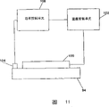
Figure 11 is the temperature controlled schematic diagram of demoulding boots.
Figure 12 A, 12B and 12C are the photos according to retaining wall masonry block of the present invention.
The specific embodiment
Summary
The invention provides an activities that is used for the production concrete masonry blocks, the masonry block that forms of technology thus, an and mould and a mold component that is used for implementing this activities, wherein, one predetermined 3-D graphic is impressed in the surface of masonry block, and the front of masonry block can directly handle or process in addition, so that the front of a masonry block of being scheduled to can be formed in the dry cast concrete masonry block or paving stone machine of a standard.That positive direct processing or processing include is molded, shaping, needle drawing shape, coining pattern, material layer are laid, and their combination, also have other activities, wherein, they can directly influence positive texture, shape, color, outward appearance, or physical property.In addition, can use the mould of many inner chambers to implement this process, so as on the dry cast concrete masonry block of standard or paving stone equipment at high speed, high yield ground produces masonry block.And, use activities of the present invention and equipment not to need the station of a splitting and/or the station of a sledge mill, and/or the station of a barreling, and relevant supplementary equipment therefore and the cost of processing of additional treatments station therewith.
Masonry block by explained hereafter of the present invention can have such structure, the wall that it allows to be configured to comprises by piling up a plurality of masonry blocks and forms retaining wall sinuous or arc, in many levels, have identical or different predetermined fronts, and formation automatically stops and shearing resistance between all layers.
To describe a preferred embodiment below, wherein, the petrous figure of a three-dimensional of being scheduled to is impressed into the front of retaining wall masonry block.Its result, masonry block and the retaining wall that when a plurality of masonry blocks are stacked into multilayer, constitutes, showing is to be formed by " natural " material structure.Activities as herein described also can be used to construct such masonry block, and they can be used for constructing the wall of building, and concrete brick, plate and paving stone.
Masonry block
The figure of giving on the front 12 can change according to the outward appearance that requires previously.Preferably, pattern simulates natural stone, so that front 12 shows natural material, rather than artificial material.The figure of the special stone that adopts can be selected according to figure that can visually joyful masonry block user.For instance, the surface of masonry block can impress the figure that is revealed as a single stone (such as korneforos stone).Perhaps, masonry block can impress the figure that is revealed as a plurality of korneforos stone that combines with plaster.Perhaps, masonry block can impress the quarry stone that is revealed as monolithic, or is stacked into the figure of the polylith open country stone of multilayer.Have inexhaustible possibility.By the demoulding that has various different graphics boots are provided, the figure that generates on the masonry block can change by changing demoulding boots.
Synthetic details and be arranged on embossment on the front is arranged on details and embossment on the masonry block front greater than what traditional splitting technology generated, and these technology also comprise the technology of above-mentioned barreling, sledge mill and the wearing and tearing of other years.Embossment on the front 12 of figure, the distance that measures peak from minimum point preferably is at least 0.5 inch (1.27cm), more preferably is at least 1.0 inches (2.54cm).
In a preferred embodiment, compare with the face of arc with the common three-dimensional portrayal seen in the retaining wall of the splitting surface of being everlasting, in the general roughly single plane between side 20,22, front 12, but so many facets available the present invention easily forms with face arc.As shown in Figure 3, front 12 is provided with slightly backward an inclination, that is, and and from the inclined angle alpha of beneath face 18 to top 16.Preferably, α is about 10 degree.Its result, 18 one apart from d below front and back 12,14 quilts were contiguous
1With contiguous above 16 one apart from d
2At interval, wherein, d
1Greater than d
2In a preferred embodiment, d
1Be about 7.625 inches (19.3675cm), and d
2Be about 6.875 inches (17.4625cm).Width d
3Preferably be about 12.0 inches (30.48cm).Also can conceive front 12 between the side 20,22 and can be facet, arc, or both combinations.In these embodiments, the front also can have receding slightly.
Usually, when the retaining wall masonry block is stacked into the multilayer that stops and when forming a wall, the part of each in lower floor above the masonry block can be seen between the front of each masonry block of lower floor and the front at each masonry block on contiguous upper strata.Top visible part forms the appearance at edge.In the situation of the masonry block of dry cast, this edge has an artificial appearance usually.By a sweptback angle with respect to the front 12 of masonry block 10 is provided, the appearance at edge can reduce or eliminate, and therefore, improves the looks of " nature " of synthetic wall.
With reference to Fig. 1-3, the back 14 of masonry block 10 is shown as the plane roughly between the side 20,22, and is approximately perpendicular to upper and lower 16,18.Yet, can conceive next 14 and depart from from the plane, for example, by being provided with one or more grooves, or be provided with one or more depressions, and still within the scope of the invention simultaneously.Next 14 width d
4Preferably be about 8.202 inches (20.833cm).
In addition, above 16 planes that in Fig. 1-3, are shown as roughly, there is no and intersect at top inner core.When a plurality of masonry blocks 10 are stacked into multilayer and when forming a wall construction, top 16 of each masonry block keeps and top 16 of other masonry block parallel relations.
Following 18 of masonry block 10 forms the top 16 of the masonry block that is suitable for engaging down in the boundary layer, with the relation of the almost parallel between keeping above the masonry block 10 when masonry block is stacked into multilayer.In a preferred embodiment, as Figure 1-3, below 18 be roughly plane and level so that it is roughly parallel to top 16.Yet, can use other below, comprise below such one that it is included in one or more sunk parts or one or more passage on following 18 the part.Above between 16 and following 18 apart from d
6Preferably be about 4.0 inches (10.16cm).
In preferable masonry block 10, as Figure 1-3, side 20,22 approximate vertical, and connect upper and lower 16,18, before connecting and back 12,14.When the side towards the back 14 when extending, at least a portion of each side 20,22 is shunk towards the opposite flank.Preferably, the total length of each side 20,22 begins from adjacent front 18 to shrink, and makes side 20,22 generally be the plane between preceding and back 12,14.Yet side 20,22 can be from beginning to shrink with a position at interval, front 12, in this case, side 20,22 will comprise one from the straight line that extends previously, non-constriction and be directed to the two the combination of next 14 constriction from straight line portion.The constriction of each side 20,22 preferably is punctured into the angle β of about 14.5 degree.
Perhaps, masonry block 10 can be provided with the side or the lateral parts of an only contraction, and the another side is substantially perpendicular to preceding and back 12,14.One has the retaining wall that at least one masonry block that shrinks the side allows structure to wriggle.
With reference to Fig. 3 A, as seen from the figure, bead 26 comprises a front 28, and it engages the back of the masonry block in the lower floor.Bead 26 also comprises preceding feather edge 32, one rear surfaces 34 of a basal surface 30, a camber between front surface 28 and basal surface 30, it be masonry block back 14 extension and form the part of the back 14 of masonry block.Front surface 28 preferably tilts into about the angle γ of 18 degree.The front surface 28 that tilts and the edge 32 of arc are formed by the shaped portion of the correspondence of mould, and the structure of mould is convenient to fill out the filling mould with dry cast concrete, and discharge bead 26 from mould.
As illustrated in fig. 1 and 2, bead 26 is extended whole distances between all sides 20,22.Yet bead does not need whole distances.For example, bead can only be extended the part of distance between all sides, and with the side at interval.Perhaps, can use two or more bead parts in the gap that is separated from each other.
With reference to Fig. 3 A, the depth d of bead 26
7Preferably be about 0.750 inch (1.90cm).This degree of depth limits the masonry block barrier force synthetic with respect to lower floor.Also can use other flange dimensions, decide on the amount of the barrier force of requirement.Rear surface 34 preferably has a height d
8Be about 0.375 inch (0.952cm).
Described notion also can be applicable to the masonry block that is used to construct building wall, and concrete brick, plate and paving stone.In these cases, can conceive within the scope of the invention, the side of masonry block or the side of brick are collapsible, can not have bead.Yet the front of figure can provide masonry block or the outward appearance of brick to decorate.
Block structures
As mentioned above, the bead 26 on the masonry block 10 provides the barrier force from the masonry block of lower floor.Its result, layer 42b tegillum 42a stops, and layer 42c tegillum 42b stops.In addition, as mentioned above, the amount of the upper part by reducing each masonry block in the lower floor, the inclination backward of front 12 reduce the edge that forms between each adjacent layer, can see between the front of each masonry block on the front of each masonry block of top part in lower floor and contiguous upper strata.
Retaining wall shown in Fig. 4 is straight.Yet, have the structure of the preferable masonry block 10 of inclined side 20,22, allow structure retaining wall that wriggle or arc, for example, as United States Patent (USP) 5,827,015 is disclosed.
The masonry block forming process
Of the present invention one additional aspect relates to the activities that forms masonry block 10.With reference to Fig. 5, a summary of this process is shown.Usually, process is from mixing the dry cast concrete that will form masonry block.The concrete that the nothing of dry cast collapses is well-known in the retaining wall masonry block field.The concrete of selecting should satisfy predetermined strength, water imbibition, density, shrinkage factor, and for the relevant standard of masonry block, so that masonry block will fully be competent at the use to it.Those skilled in the art can easily select the selection of the block criteria that meets the demands.In addition, program and the equipment that mixes the constituent of thousand formula concretings is known in the present technique field.
In case concrete mixes, it promptly is sent near one the mould and holds concrete hopper.Described in hereinafter, die assembly 50 comprises that at least one is applicable to that the masonry block that forms preferable masonry block forms inner chamber 56.This inner chamber 56 is in its top and bottom-open.In the time will forming a masonry block, a molded panel is positioned at the bottom of mould, to close the bottom of inner chamber 56.Then, the dry cast concrete of appropriate amount utilizes one or more withdrawing devices of presenting to pass through the top-loaded of inner chamber 56 in masonry block formation inner chamber from hopper.Being used for transmitting dry cast concrete is well know in the art with the activities and the equipment that load masonry block formation inner chamber.
Dry cast concrete in the inner chamber 56 next must be fine and close and condensing with it.This mainly realizes by the vibration of dry cast concrete, simultaneously also in conjunction with from the top quality to dry cast concrete exert pressure.The vibration (vibroplatform) that applies molded panel that can be by being positioned at mould below of vibration, or the vibration (mould vibration) by mold box, or pass through the combination of two kinds of effects.Applying of pressure by a head (will discuss hereinafter), it carries one or more demoulding boots, and it is from the quality of top contact dry cast concrete.The time of vibration and compression and order can change, and decide on the characteristic of dry cast concrete and the result of requirement.Suitable order and the selection of time and effect, and the type of vibration force is all within the scope that those skilled in the art grasp.In general, what these power contributed to inner chamber 56 fills out filling fully, so that does not have unfavorable hole in the masonry block of finished product, and condensing dry cast concrete, so that the masonry block of finished product has weight, density and the performance characteristic of requirement.
Pressure applies by a demoulding boots 94, and the top of the dry cast concrete in its contact inner chamber 56 that descends is with dense concrete.Demoulding boots 94 form the masonry block of a precuring solid, that connect with the vibration effect with the concrete in the fine and close inner chamber 56.In a preferred embodiment, demoulding boots also comprise the figure 96 of a three-dimensional on its face, and when demoulding boots dense concrete, it is used for producing graph of a correspondence on the masonry block of the precuring that generates.Preferably, quilt is with that part of front that comprises masonry block of the pre-cured block of the demoulding boot upper contact of figure.
After condensing, the masonry block of precuring is discharged from inner chamber.Preferably, molded panel 82 descends with respect to die assembly, and the discharge of beginning masonry block continues decline demoulding boots 94 by dies cavity, helps masonry block demoulding from inner chamber.Then, demoulding boots upwards promote dies cavity, and mould prepares to repeat this manufacturing process.
If masonry block has the sidewall of one or more contractions, then Dui Ying mould side wall (will be described in more detail below) must be arranged in the mould.Such mould side wall must be suitable for moving to primary importance, and is fine and close and condensing to dry cast concrete to allow that mould is filled out filling, also must be suitable for moving to the second place, do not damage the masonry block of precuring to allow the demoulding.
In case the masonry block of precuring fully takes out from inner chamber, masonry block can be transmitted and move apart die assembly, so that curing thereafter.The curing of masonry block can be adopted any method known to the skilled in the present technique field.Be applicable to that the example of putting into practice solidification process of the present invention comprises air curing, high pressure, and steam cure.These any methods that are used to solidify masonry block can be adopted by those skilled in the art.
In case after solidifying, masonry block can be packaged good in order to storing and being transported to the building site thereafter, then, make the structure that is used for forming the retaining wall 40 in Fig. 5 with the masonry block of other curing.
Die assembly
Being used for putting into practice die assembly 50 according to the present invention of the present invention is shown among Fig. 6-10.Die assembly 50 is made by the material that can bear pressure in the pre-cured block forming process, and this material can also provide enough anti abrasive life-spans.
In addition, die assembly 50 is designed to: the masonry block of precuring, comprise the masonry block of the side that has lower lip or bead and/or one or more contractions, and they can be discharged by the bottom of die assembly.
With reference to Fig. 6, die assembly 50 comprises a mould 52 and one and the interact compressing head assembly 54 of (describing hereinafter) of mould 52.Mould 52 comprises that at least one masonry block that is formed on wherein forms inner chamber 56.In a preferred embodiment, the size of mould 52 is used for the masonry block machine of the U.S. of standard " a time three ", it has the molded panel size of a standard, be approximately 18.5 inches (47.0cm) and take advantage of 26.0 inches (66.0cm), this size is used for making three masonry blocks on molded panel above it.Mould 52 comprises that a plurality of roughly the same masonry blocks form inner chamber 56.Fig. 7 illustrates five masonry blocks that are arranged side by side and forms inner chambers 56, and when making the masonry block of preferred size on the molded panel in " a time three " of a standard, this also is possible.Certainly.In use, bigger machine uses bigger molded panel, and this technology can be used in bigger and the less machine.The quantity of the possible dies cavity in single mold is decided on the scale of machine and the size of molded panel.A plurality of masonry blocks form inner chamber 56 allows to increase masonry block from single mold 52 production.
With reference to Fig. 7, inner chamber 56 is formed by demarcation strip 58, comprises an external demarcation strip, a plurality of in demarcation strips, and the shared end liners 60 of a pair of each inner chamber 56.Use outer and inner dividing plate and end liners, come to form the formation inner chamber of masonry block in mould, the technician knows in the present technique field.Demarcation strip and end liners form the border of masonry block inner chamber, and are provided at the surface that contacts with pre-cured block in the masonry block forming process, and thus, they are easy to wearing and tearing.Therefore, demarcation strip and end liners are removably mounted in the mould 52 usually, can be replaced when damaging if become with their whens wearing and tearing of box lunch or they.Thisly demarcation strip is installed in mould and end liners forms inner chamber to form masonry block, and is allowed to take out the technology of partition wall and end liners, the technician knows in the present technique field.
In a preferred embodiment, demarcation strip 58 forms upper and lower 16,18 of masonry block 10, and end liners 60 forms side 20,22.For simplicity, demarcation strip and end liners (are included in claims) sidewall that is referred to as inner chamber hereinafter.Therefore, sidewall is meant demarcation strip and end liners, also refers to be used for to limit any other similar structures that masonry block forms the border of inner chamber.
Referring now to Fig. 8, single masonry block forms the part of inner chamber 56 shown in the figure.The inner chamber 56 that is formed by sidewall 58,60 has a top 64 of opening wide and a bottom 66 of opening wide.As shown in the figure, sidewall 60 (for example, end liners) top is connected to the suitable encirclement structure of mould 52 by pivot 62, to allow sidewall 60 between as shown in Figure 8 a fastening position and a retracted position, to pivot, in the former position, sidewall 60 shrinks toward each other, and in latter position, sidewall 60 is approximate vertical and parallel (not shown) each other.In the position of withdrawal, the bottom of inner chamber 56 is wide with the dies cavity top at least, and this allows the masonry block of precuring to discharge by the bottom of opening wide.When only some shrinks in the side 20,22 of masonry block, only the counterpart of sidewall 60 will pivot.The following sidewall 58 that forms masonry block 10 also is shown among Fig. 8, does not give and illustrating and form other sidewall 58 above the masonry block.
In order to form preferable masonry block 10, require pivotal side walls 60.As mentioned above, masonry block 10 forms " towards last " in mould 52, is formed the sidewall of its contraction by all sidewalls 60.Therefore, when they tilt as illustrated in fig. 8, the side 20,22 of the contraction of the sidewall 60 shaping pre-cured block of contraction.Yet the Hou portion of masonry block is wider than in the front portion of the masonry block of precuring.In order to discharge the masonry block of precuring by the bottom of opening wide 66, sidewall 60 must outwards pivot, so that the masonry block of precuring can move downward by the bottom of opening wide.
In the process of introducing concrete and fine and close dry cast concrete thereafter, biasing mechanism 68 is set sidewall 60 is remained on the position of contraction, it is in the process of discharging pre-cured block, and permission sidewall 60 is pivoted to a vertical position.Preferably, to be connected to for all inner chambers 56 be that like this, the public mechanism's (see figure 7) that moves through of each sidewall 60 is controlled on public each sidewall 60 to a single biasing mechanism 68.Biasing mechanism 68 is shown as and comprises air bag, and it will be by using air or similar gas controlled.The suitable entrance and exit port of air is set, and a source of high pressure air.Also can use other the biasing mechanism except that air bag.For example, can use hydraulic cylinder or pneumatic linear actuator.
When compressed air, the position that air bag will force sidewall 60 to arrive as shown in Figure 8.When arriving the moment of discharging pre-cured block, compressed air is discharged from air bag, and when molded panel descended, along with pre-cured block is discharged by open bottom, this allowed sidewall 60 outwards to pivot under the effect of the power of pre-cured block.In the process that masonry block is discharged, sidewall 60 keeps the contacts side surfaces with pre-cured block.Perhaps, can be connected on the sidewall 60, to force sidewall to arrive the position of withdrawal when the air bags such as the biasing mechanism of disc spring.In this case, along with molded panel 82 begins to descend and the discharge of initial masonry block, sidewall 60 will be forced to the retracted position, and sidewall 60 will not contact the side of the masonry block in the discharge process.After discharging, by air bag is pressurizeed again, sidewall 60 turns back to the position of the inclination of closing.
Not pivotal side walls 60, can use other mechanism to allow the motion of sidewall 60, so that the masonry block of precuring is discharged.For example, sidewall 60 can be mounted to the same with the top of the dies cavity at least wide position in position that inwardly slides into as shown in Figure 8 and the bottom that outwards slides into inner chamber 56.Sliding motion can use a rail system that sidewall wherein is installed to realize.
As shown in Figure 8, each sidewall 60 comprises the shaped surface 76 of one side to inner chamber 56.Shaped surface 76 is the plane basically.Consequently form the side 20,22 on the plane basically of masonry block 10.
Referring now to Fig. 9, form upper and lower 16 of masonry block 10,18 sidewall 58 shown in the figure.In molding process fixed sidewall 58 be basically vertically to.
16 sidewall 58 (left side wall 58 among Fig. 9) comprises the profiled surface 78 of one side to inner chamber 56 above forming.The surface 78 is the plane basically, and it causes forming top 16 of plane basically.
Below forming 18 sidewall 58 (right side wall 58 among Fig. 9) comprise a contiguous open bottom 66, in the undercutting of its bottom margin, or " instep " part 80.The secondary inner chamber that one bead of bottom cutting portion 80 combination die making sheet 82 formation together inner chamber 56 forms, described molded panel 82 is incorporated into the bottom of mould 52 in molding process, to close unlimited mold bottom 66 provisionally.The secondary inner chamber that bead forms has a shape, and it causes forming the bead 26 of masonry block 10.
Especially, bottom cutting portion 80 comprises that a profiled surface 84, that forms the front surface 28 of bead 26 forms the profiled surface 86 of the basal surface 30 of bead 26, and the profiled surface 88 of the leading edge 32 of a formation bead 26.Be the part of next 14 beads 26 of extending,, form thereon by molded panel 82 together with the remainder of back 14. Surface 84 and 86 shape is convenient to so that bead 26 can fully form, simultaneously, also help bead 26 release from surface 84,86 introducing concrete and filling out with concrete in the process of dense concrete thereafter and irritate bottom cutting portion 80 in the process that masonry block is discharged.
Have on below masonry block in the situation of the side that a bead not do not shrink, sidewall 60 will be vertically directed shrinks replacing.In addition, do not have bead on below masonry block and have in the situation of side of contraction, undercutting 80 will not exist.In the situation of the side that does not have bead on below masonry block and do not have to shrink, undercutting 80 will not exist, and sidewall 60 will be vertically directed.
With reference to Fig. 6 and 8, visible assembly 54 comprises that one is the compressing head 90 of the form of plate among the figure.90 are activated by actuating mechanism in mode well know in the art, so that 90 vertically move up and down, realizing the dry cast concrete in the fine and close dies cavity 56, and help to deviate from the masonry block of precuring from mould 52.
What connect that 90 and from the beginning 90 bottom to the end extends is a plurality of supports 92, and as shown in Figure 6, a support is used for a masonry block and forms inner chamber 56.Support 92 each intervals, each longitudinal axis that supports is oriented orthogonal to a plane of 90, and generally extends through masonry block along the center and form inner chamber 56.
Demoulding boots 94 shown in Fig. 6,8,9 and 10 are connected to and respectively support 92 end.Rectangular and its size of demoulding boots 94 is made like this: it can with contact concrete and dense concrete, and move through inner chamber by the inner chamber 56 of the top centering correspondence of opening wide in the process of the masonry block of discharging precuring.The size of demoulding boots 94 only is slightly less than the size of the open top 64 of inner chamber 56, and like this, demoulding boots 94 can be engaged in the inner chamber 56, so that very little gap or very close to each other between the sidewall 58,60 of the sidewall of demoulding boots 94 and formation inner chamber.This farthest reduces the sidewall of demoulding boots 94 in compression process and forms concrete escape between the sidewall 58,60 of inner chamber, and makes the area maximum of front of the masonry block of demoulding boots 94 contacts.
As Figure 10 clearly shown in, bead 98a, 98b are formed on the opposite end of face of demoulding boots 94. Bead 98a, 98b are curved, to form edge 24a, the 24b of rounding on the front 12 of masonry block.If requirement, then arcuate flange can be arranged on two remaining ends of demoulding boots 94, so that form the edge of upper and lower rounding in front on 12.
As mentioned above, the one side of demoulding boots 94 is preferably provided with a predetermined figure, and like this, when demoulding boots 94 dense concretes, figure just is stamped on the front of masonry block.Figure is simulates natural stone preferably, so that natural stone is imitated out in the front of synthetic masonry block, thus, causes masonry block to seem more natural and " rock-like ".Various figure 96 can be arranged on the demoulding boots 94, wishes that on people the outward appearance of the front that reaches is decided.Except figure 96, or separate with figure 96, the face of demoulding boots 94 can be shaped and masonry block that obtain to portray or arc front.Really, the face of demoulding boots 94 can graphically and/or in any mode that people wish be shaped, so that reach the appearance of desirable masonry block front.
Figure 10 provides an example that can be arranged on the predetermined figure 96 of one on the demoulding boots 94.Figure 96 simulates natural stone.According to predetermined 3-D graphic, figure 96 is preferably processed on the face of demoulding boots.The process of the demonstration of the figure that formation is scheduled on demoulding boot upper is as follows.
At first, select to have the one or more natural rocks that it is believed that visually joyful surface.Then, scan the surface of one or more rocks with a digital scanner.The example that is used for putting into practice suitable scanner of the present invention is the Laser Design Surveyor 1200 with RPS150 head, buys the product that it can be produced from the Laser Design Incorporated in the Minneapolis city of bright Ni Sudazhou.The linear precision that LaserDesign Surveyor 1200 has is 0.0005 in XYZ coordinate ", and resolution ratio is 0.0001 ".Collection is also operated the scan-data that mixes for each scanning of a surface for the scan-data of rock surface, to form the seamless data mixing of various rock surfaces.Gather and the software of operation scan-data is well know in the art, for example, the DataSculpt that provides by the Laser DesignIncorporated in the Minneapolis city of bright Ni Sudazhou.
Then, data mixing is carried out proportional zoom and/or is trimmed into the size of masonry block front.The data mixing of proportional zoom is represented from one of the rock surface mixing of each self-scanning single rock surface.Then, the blended data of proportional zoom outputs to one or three or four numerically controlled edge knurling machine, so that demoulding boots 94 are carried out annular knurl.Put into practice suitable edge knurling machine of the present invention and be the Mikron VCP600 that the Mikron AG Nidau by the Nidau of Switzerland produces.This edge knurling machine will be milled on the face of the demoulding boots 94 that are properly mounted in known manner on the edge knurling machine by the mirror image of the rock surface of the blended data of proportional zoom representative.Consequently Yu Ding figure is milled on the face of demoulding boots 94, and it when demoulding boots 94 dense concretes, causes predetermined figure is impressed on the front of masonry block again.
This process can repeatedly produce the additional demoulding boots with identical or different face figures.This point is favourable, because the face of the figure of each demoulding boots is through frayed, so when figure becomes when exceedingly wearing and tearing, demoulding boots are replaced needs.In addition, by forming the figure of various predetermined demoulding boots, can realize the appearance of various different masonry blocks front.The surface of a plurality of different rocks by array sweeping can form the figure of other demoulding boots.
As mentioned above, be arranged on synthetic details and embossment on the masonry block front, can be significantly greater than details and embossment on the front that is formed on masonry block by traditional splitting technology and above-mentioned other the technology of years wearing and tearing front.If requirement, the data that can operate scanning, so that increase or reduce to be milled into the interior embossment of demoulding boots, it will change the embossment that finally is arranged on the masonry block front.
Well-known in the present technique field, dry cast concrete can have the tendency that adheres to such as on the die surface of the patterned surface of demoulding boots 94.Known have various technology to improve the ability that discharges demoulding boots 94 from dry cast concrete, one or more being used in the practice of the present invention in them.For example, designing the figure that is formed on the demoulding boots improves release rather than hinders release.In this, must in figure, adopt suitable drag angle.Above-mentioned figure formation technology allows the image of operation scanning to form suitable drag angle.Between all circulations of machine, the releasing agent such as thin mist of oil can be sprayed on the demoulding boots.Can use the vibration of head to improve release.Also can apply heat and to demoulding boots, improve release.The heating mould assembly prevents the adhesion of dry cast concrete, is known in the present technique field.In the present invention, owing to be imparted to the figure of the details on the masonry block front, so, prevent adhesion even seem more important.Especially, importantly can control the temperature of demoulding boots, so that temperature can remain on the selected level.
Preferably, shown in the chart among Figure 11, a heater 100 is connected on the demoulding boots 94, is used for heating demoulding boots.Heater 100 is subjected to the control of a temperature control unit 102.Be installed in the temperature of the thermocouple 104 detection demoulding boots on the demoulding boots 94, and provide the power control unit 106 of electric power to control module 102 and heater 100 with this message transport to one.System designs like this: when the temperature of demoulding boots 94 drops to the predeterminated level that detects as thermocouple 104 when following, then supply power to heater 100 to improve the temperature of demoulding boots.When the temperature of demoulding boots reached the predeterminated level that detects as thermocouple 104, heater 100 cut out.Therefore, on the level that the temperature of demoulding boots can keep selecting.Preferably, control module 102 is designed to: according to employed dry cast concrete, allow to limit minimum and maximum temperature levels.In a preferred embodiment, the surface temperature of demoulding boots 94 remains between 120 and 130 .
Claims (37)
1. a method that is used for producing masonry block (10), described masonry block (10) has upper and lower (16,18), a front (12), one back (14), relative side (20,22), and the bead (26) of the one of the extension of the bottom below masonry block, this method comprises the steps:
One mould (52) is provided, it has a plurality of sidewalls (58 that form a dies cavity (56), 60), dies cavity has a top (64) of opening wide and a bottom (66) of opening wide, one the first side wall (58) has the bottom cutting portion (80) of the open bottom of a contiguous dies cavity, one second sidewall (60) perpendicular to described the first side wall (58) of described mould (52) comprises one first sidewall sections that shrinks, first side member of shrinking with respect to vertically to orientation at angle so that its underpart is wider than on dies cavity top, and first sidewall sections that shrinks traverses whole distances of the dies cavity between two relative sidewalls (58) of a contiguous sidewall (60) and extends;
The flat surface of one molded panel (82) is positioned at the bottom of mould (52), so that the bottom of opening wide fully (66) of closing molding inner chamber (56) provisionally, wherein, the cooperation of the bottom cutting portion (80) of molded panel (82) and the first side wall (58) and form a dies cavity bead-secondary inner chamber is shaped; By the mould top of opening wide (64) dry cast concrete is incorporated in the dies cavity (56);
First sidewall sections that shrinks is moved to a position, and in this position, discharge by the bottom that reopens of dies cavity with the masonry block that allows precuring with the top of dies cavity is same wide at least the bottom of dies cavity;
Fine and close dry cast concrete is to form the masonry block of a precuring, and its back is seated on the molded panel (82), and the front of masonry block is towards last;
Reopen the bottom of the dies cavity (56) of Temporarily Closed;
Discharge the concrete masonry blocks of precuring from dies cavity (56) by the bottom of the dies cavity that reopens; And
The concrete masonry blocks of cured pre-cure.
2. the method for claim 1, it is characterized in that, further comprising the steps of: after being incorporated into dry cast concrete in the dies cavity, the top of opening wide (64) by dies cavity, to have one and comprise that the demoulding boots (94) of the face of a 3-D graphic (96) are incorporated in the dies cavity (56), and the face with figure of demoulding boots (94) is pressed on the dry cast concrete that is contained in the dies cavity, on the front with the masonry block that figure is stamped in precuring.
3. method as claimed in claim 2 is characterized in that, figure (96) simulates natural stone on the face of demoulding boots (94).
4. method as claimed in claim 3 is characterized in that, described fine and close step involving vibrations is contained in the concrete in the dies cavity.
5. the method for claim 1, it is characterized in that, the sidewall (60) of the mould relative with second sidewall (60) comprises second sidewall sections that shrinks that one and first sidewall sections that shrinks is relative, wherein, just before concrete is introduced step, second side member of shrinking with respect to the vertical direction orientation at angle, so that dies cavity is in concrete introducing and fine and close step process, its bottom is wider than at its top, wherein, second sidewall sections that shrinks is installed movably, and comprise such step: second sidewall sections that shrinks is moved to a position, in this position, the bottom of dies cavity is wide equally with the top of dies cavity at least, discharges by the bottom that reopens of dies cavity with the masonry block that allows precuring.
6. method as claimed in claim 5, it is characterized in that, first and second parts of shrinking of mould side wall (60) are introduced inclined orientation before by the concrete that bias force is biased to them, and wherein, bias force discharges with the masonry block that allows precuring discharges from mould.
7. method as claimed in claim 6 is characterized in that, bias force is provided with by air bag (68).
8. the method for claim 1 is characterized in that, the bottom of the dies cavity of Temporarily Closed (56) reopens, and by with respect to mould (52) decline molded panel (82), the masonry block of precuring is discharged by the bottom of opening wide (66) of dies cavity.
9. the method for claim 1 is characterized in that, described mould (52) comprises a plurality of described dies cavities (56), and they are with single molded panel (82) operation, so that side by side molded a plurality of masonry blocks
10. a method that is used for producing concrete block (10), described masonry block has upper and lower (16,18), the front of one figure (12), one back (14) and relative side (20,22), first side in the described side has one first part of shrinking, it extends towards described back along with the side and towards described second side collapse, this method comprises the steps:
One mould (52) is provided, it has a plurality of sidewalls (58,60) that form a dies cavity (56), dies cavity has a top (64) of opening wide and a bottom (66) of opening wide, one sidewall (60) of mould comprises one first sidewall sections that shrinks, it with respect to the vertical direction orientation at angle, so that its bottom is wider than at the top of dies cavity, and first sidewall sections that shrinks traverses whole distances of the dies cavity between two the relative sidewalls (58) that are close to a sidewall (60) and extends;
One molded panel (82) is positioned at the bottom of mould (52), so that the bottom of opening wide (66) of closing molding inner chamber provisionally;
By the mould top of opening wide (64) dry cast concrete is incorporated in the dies cavity (56);
Fine and close dry cast concrete is to form the concrete masonry blocks of a precuring, its back is seated on the molded panel (82), and the front of masonry block is towards last, described fine and close step comprises: the top of opening wide (64) by dies cavity (56) will have one and comprise that the demoulding boots (94) of the face of 3-D graphic (96) are incorporated in the dies cavity, and the face with figure of demoulding boots (94) is pressed on the dry cast concrete that is contained in the dies cavity, on the front with the concrete masonry blocks that figure is stamped in precuring;
Reopen the bottom of the dies cavity (56) of Temporarily Closed;
First sidewall sections that shrinks of mould is moved to a position, and in this position, the bottom of dies cavity (56) is at least enough wide discharges by the bottom that reopens of dies cavity with the masonry block that allows precuring;
Discharge the masonry block of precuring from dies cavity by the bottom of the dies cavity that reopens; And
The masonry block of cured pre-cure.
11. method as claimed in claim 10 is characterized in that, described fine and close step involving vibrations is contained in the concrete in the dies cavity.
12. method as claimed in claim 10, it is characterized in that, the sidewall (60) of the mould relative with a described sidewall (60) comprises one second sidewall sections that shrinks, it is relative with first sidewall sections that shrinks, and the dies cavity that traverses between two the relative sidewalls (58) that are close to a sidewall extends whole distances, wherein, just before concrete is introduced step, second side member of shrinking with respect to the vertical direction orientation at angle, so that dies cavity is in concrete introducing and fine and close step process, its bottom is wider than at its top, wherein, second sidewall sections that shrinks is installed movably, and comprise such step: described second sidewall sections that shrinks is moved to a position, in this position, the bottom of dies cavity is wide equally with the top of dies cavity at least, discharges by the bottom that reopens of dies cavity with the masonry block that allows precuring.
13. method as claimed in claim 12, it is characterized in that, sidewall (60) part that first and second of mould shrinks is introduced inclined orientation before by the concrete that bias force is biased to them, and wherein, bias force discharges with the masonry block that allows precuring discharges from mould.
14. method as claimed in claim 12 is characterized in that, bias force is provided with by air bag (68).
15. method as claimed in claim 10 is characterized in that, the bottom of the dies cavity of Temporarily Closed (56) reopens, and by with respect to mould (52) decline molded panel (82), the masonry block of precuring is discharged by the bottom of opening wide (66) of dies cavity.
16. method as claimed in claim 10 is characterized in that, described mould (52) comprises a plurality of described dies cavities (56), and they are with single molded panel (82) operation, so that side by side molded a plurality of masonry blocks
17. method as claimed in claim 10, it is characterized in that, one sidewall (58) of mould comprises the bottom cutting portion (80) of the bottom of opening wide (66) of a contiguous dies cavity, and the bottom cutting portion cooperation of molded panel (82) and sidewall, with form dies cavity a bead-secondary inner chamber is shaped.
18. method as claimed in claim 10 is characterized in that, molded panel (82) comprises a flat surface, whole bottom of opening wide of its closing molding inner chamber.
19. one is used for forming the die assembly (50) of masonry block (10) of the dry cast of a precuring, described masonry block has upper and lower (16,18), one front (12), one back (14), relative side (20,22), and the bead (26) of the one of the extension of the bottom below masonry block, this die assembly comprises:
A plurality of sidewalls (58,60), they form the dies cavity (56) with a mould top (64) of opening wide and a mold bottom (66) that opens wide, one the first side wall of described sidewall (58) comprises the bottom cutting portion (80) of a contiguous mold bottom that opens wide, together with a flat surface of the molded panel (82) of whole bottoms of opening wide (66) of closing molding inner chamber (56) form dies cavity a bead-secondary inner chamber is shaped, second sidewall (60) of mould comprises first sidewall sections that shrinks of installing movably, like this, it is removable between the primary importance and the second place, in primary importance, the first side wall part tilts with respect to vertical direction and makes the top of dies cavity be wider than its bottom with in dry cast concrete is incorporated into dies cavity the time, and in the second place, the bottom of dies cavity is at least enough wide discharges by the bottom of dies cavity with the masonry block that allows precuring, wherein, first sidewall sections that shrinks traverses whole distance extensions of the dies cavity between two the relative sidewalls (58) that are close to second sidewall (60); And one have a demoulding boots (94) that comprise the face of 3-D graphic (96), it is used for being incorporated in the dies cavity by the top of opening wide (64) of dies cavity, and the face with figure of demoulding boots (94) is pressed on the dry cast concrete that is contained in the dies cavity, on the front with the concrete masonry blocks that figure is stamped in precuring.
20. die assembly as claimed in claim 19 is characterized in that, figure (96) simulates natural stone on the face of demoulding boots (94).
21. die assembly as claimed in claim 20, it is characterized in that, described demoulding boots (94) comprise that one centers on the bead (98a, 98b) of the periphery of picture surface, and described bead is an arc, so that produce the edge (24a, 24b) of rounding on the front of masonry block.
22. die assembly as claimed in claim 19 is characterized in that, the remainder that has the described sidewall (58) of described undercutting (80) is the plane basically, and vertically extends.
23. die assembly as claimed in claim 19, it is characterized in that, the sidewall (60) of the mould relative with described second sidewall (60) comprises one second sidewall sections that shrinks, it is relative with first sidewall sections that shrinks, and whole distances of traversing the dies cavity between two the relative sidewalls (58) that are close to second sidewall are extended, wherein, second sidewall sections that shrinks is installed movably, so that it is removable between the primary importance and the second place, in primary importance, second sidewall sections tilts with respect to vertical direction, with in dry cast concrete is incorporated into dies cavity the time, make the top of dies cavity be wider than its bottom, and in the second place, the bottom of dies cavity is at least enough wide discharge by the bottom of dies cavity with the masonry block that allows precuring.
24. die assembly as claimed in claim 23 is characterized in that, the sidewall sections of described contraction pivots near its end at the contiguous mould top of opening wide.
25. die assembly as claimed in claim 23 is characterized in that, also comprises a mechanism (68), the sidewall sections of its each described contraction of setovering is to the position that tilts.
26. die assembly as claimed in claim 25 is characterized in that, the mechanism (68) of the sidewall sections of each described contraction that is used for setovering comprises that one is connected to the air bag of each sidewall sections that shrinks.
27. die assembly as claimed in claim 23 is characterized in that, the sidewall sections of each described contraction comprises a surface (76) towards the plane of dies cavity.
28. die assembly as claimed in claim 19 is characterized in that, comprises a plurality of described dies cavities (56), they are with single molded panel (82) operation, so that side by side molded a plurality of masonry blocks.
29. one is used for forming the die assembly (50) of masonry block (10) of the dry cast of a precuring, described masonry block has upper and lower (16,18), one front (12), one back (14), relative side (20,22), and the bead (26) of the one of the extension of the bottom below masonry block, this die assembly comprises:
A plurality of sidewalls (58,60), they form the dies cavity (56) with a mould top (64) of opening wide and a mold bottom (66) that opens wide, one the first side wall of the described sidewall (60) of mould comprises first sidewall sections that shrinks of installing movably, so that it is removable between the primary importance and the second place, in primary importance, the first side wall part tilts with respect to vertical direction, with in dry cast concrete is incorporated into dies cavity the time, make the top of dies cavity be wider than its bottom, and in the second place, the bottom of dies cavity has enough width and discharges by the bottom of dies cavity with the masonry block that allows precuring, wherein, first sidewall sections that shrinks whole distances of traversing the dies cavity between two relative sidewalls (58) of contiguous the first side wall (60) are extended; And
One demoulding boots (94), it has a face that comprises the figure (96) of a three-dimensional, so that the top of opening wide (64) by dies cavity is incorporated into dies cavity, the face with figure (96) of demoulding boots (94) is stamped on the dry cast concrete that is contained in the dies cavity, and the front of masonry block of giving precuring is with a figure.
30. die assembly as claimed in claim 29 is characterized in that, figure (96) simulates natural stone on the face of demoulding boots (94).
31. die assembly as claimed in claim 30, it is characterized in that, described demoulding boots (94) comprise that one centers on the bead (98a, 98b) of the periphery of picture surface, and described bead is an arc, so that produce the edge (24a, 24b) of rounding on the front of masonry block.
32. die assembly as claimed in claim 29, it is characterized in that, the sidewall (60) of the mould relative with described the first side wall (60) comprises one second sidewall sections that shrinks, it is relative with first sidewall sections that shrinks, and whole distances of traversing the dies cavity between two relative sidewalls (58) of contiguous the first side wall (60) are extended, wherein, second sidewall sections that shrinks is installed movably, so that it is removable between the primary importance and the second place, in primary importance, second sidewall sections tilts with respect to vertical direction, with in dry cast concrete is incorporated into dies cavity the time, make the top of dies cavity be wider than its bottom, and in the second place, the bottom of dies cavity is at least enough wide discharge by the bottom of dies cavity with the masonry block that allows precuring.
33. die assembly as claimed in claim 32 is characterized in that, the sidewall sections of described contraction pivots near its end at the contiguous mould top of opening wide (64).
34. die assembly as claimed in claim 32 is characterized in that, also comprises a mechanism (68), the sidewall sections of its each described contraction of setovering is to primary importance.
35. die assembly as claimed in claim 34 is characterized in that, the mechanism (68) of the sidewall sections of each described contraction that is used for setovering comprises that one is connected to the air bag of each sidewall sections that shrinks.
36. die assembly as claimed in claim 32 is characterized in that, the sidewall sections of each described contraction comprises a surface (76) towards the plane of dies cavity.
37. die assembly as claimed in claim 29 is characterized in that, comprises a plurality of described dies cavities (56), they are with single molded panel (82) operation, so that side by side molded a plurality of masonry blocks.
Applications Claiming Priority (2)
| Application Number | Priority Date | Filing Date | Title |
|---|---|---|---|
| US10/038,639 | 2002-01-04 | ||
| US10/038,639 US7140867B2 (en) | 2002-01-04 | 2002-01-04 | Mold for making a masonry block |
Publications (2)
| Publication Number | Publication Date |
|---|---|
| CN1612968A CN1612968A (en) | 2005-05-04 |
| CN100359113C true CN100359113C (en) | 2008-01-02 |
Family
ID=21901054
Family Applications (1)
| Application Number | Title | Priority Date | Filing Date |
|---|---|---|---|
| CNB02826729XA Expired - Fee Related CN100359113C (en) | 2002-01-04 | 2002-12-27 | Masonry block and method of making same |
Country Status (15)
| Country | Link |
|---|---|
| US (3) | US7140867B2 (en) |
| EP (3) | EP2559824A1 (en) |
| JP (2) | JP4313679B2 (en) |
| KR (1) | KR100921853B1 (en) |
| CN (1) | CN100359113C (en) |
| AT (1) | ATE518997T1 (en) |
| AU (2) | AU2002360807B2 (en) |
| CA (2) | CA2472224C (en) |
| DK (1) | DK1466058T3 (en) |
| ES (1) | ES2368324T3 (en) |
| MX (1) | MXPA04006525A (en) |
| NO (1) | NO336251B1 (en) |
| NZ (3) | NZ534313A (en) |
| PT (1) | PT1466058E (en) |
| WO (1) | WO2003060251A1 (en) |
Families Citing this family (113)
| Publication number | Priority date | Publication date | Assignee | Title |
|---|---|---|---|---|
| US7140867B2 (en) * | 2002-01-04 | 2006-11-28 | Anchor Wall Systems, Inc. | Mold for making a masonry block |
| US7208112B2 (en) * | 2002-01-04 | 2007-04-24 | Anchor Wall Systems, Inc. | Concrete block and method of making same |
| US6874494B2 (en) * | 2002-03-20 | 2005-04-05 | Anchor Wall Systems, Inc. | Block splitting assembly and method |
| CA2387181A1 (en) * | 2002-05-22 | 2003-11-22 | Les Materiaux De Construction Oldcastle Canada Inc. | An artificial piece of masonry and a kit for forming a masonry wall |
| US20040098938A1 (en) * | 2002-11-22 | 2004-05-27 | Anchor Wall Systems, Inc. | Decorated concrete block |
| US20040218985A1 (en) * | 2003-04-30 | 2004-11-04 | Klettenberg Charles N. | Method of making a composite masonry block |
| USD501935S1 (en) * | 2003-07-21 | 2005-02-15 | Keystone Retaining Wall Systems, Inc. | Wall block |
| US7980842B2 (en) | 2003-07-29 | 2011-07-19 | Ness Inventions, Inc. | Concrete block mold with moveable liner and heater |
| US20050211871A1 (en) * | 2003-07-29 | 2005-09-29 | Ness John T | Interlocking masonry blocks and method and system of making interlocking masonry blocks |
| US20050121830A1 (en) * | 2003-07-29 | 2005-06-09 | Ness John T. | Masonry blocks and method and system of making masonry blocks |
| US20050120670A1 (en) * | 2003-07-29 | 2005-06-09 | Ness John T. | Masonry blocks and method and system of making masonry blocks |
| US8123512B2 (en) | 2003-07-29 | 2012-02-28 | Ness Inventions, Inc. | Concrete block mold with moveable liner |
| US8186644B2 (en) * | 2003-07-29 | 2012-05-29 | Ness Inventions, Inc. | Concrete block mold with movable liners with master bar |
| US7175414B2 (en) * | 2003-07-29 | 2007-02-13 | Ness Inventions, Inc. | Block mold having moveable liner |
| US7156645B2 (en) * | 2003-07-29 | 2007-01-02 | Ness Inventions, Inc. | Concrete block mold with moveable liner |
| US7261548B2 (en) * | 2003-07-29 | 2007-08-28 | Haberman Machine | Concrete block mold with moveable liner |
| US7704435B2 (en) * | 2004-07-30 | 2010-04-27 | Rampf Molds Industries, Inc. | Apparatus and method for utilizing a universal plunger |
| US20060191231A1 (en) * | 2005-01-13 | 2006-08-31 | Ness John T | Masonry blocks and method of making masonry blocks having overlapping faces |
| US7500845B2 (en) | 2005-01-13 | 2009-03-10 | Ness Inventions, Inc. | Apparatus and method for forming retaining wall blocks with variable depth flanges |
| US7743574B2 (en) * | 2005-02-11 | 2010-06-29 | Anchor Wall Systems, Inc. | System of blocks for use in forming a free standing wall |
| US7575700B2 (en) * | 2005-03-01 | 2009-08-18 | Pampf Molds Industries, Inc. | Apparatus and method for a mold alignment system |
| CA2544152C (en) * | 2005-04-21 | 2013-06-11 | Les Materiaux De Construction Oldcastle Canada Inc./ Oldcastle Building Products Canada Inc. | Improvement in a molding apparatus for producing dry cast products having textured side surfaces |
| US7470121B2 (en) | 2005-05-10 | 2008-12-30 | Ness Inventions, Inc. | Block mold having moveable liner |
| US7704434B2 (en) * | 2005-06-07 | 2010-04-27 | Anchor Wall Systems, Inc. | Concrete block with beveled core opening edge |
| US7862763B2 (en) * | 2005-06-23 | 2011-01-04 | Anchor Wall Systems, Inc. | Methods of quality control in concrete block production |
| US20070009628A1 (en) * | 2005-07-11 | 2007-01-11 | Rampf Molds Industries, Inc. | Systems and methods for attaching and aligning a tamperhead in production machinery |
| US7674420B2 (en) * | 2005-08-03 | 2010-03-09 | Anchor Wall Systems, Inc. | Dimensional control of concrete blocks |
| US20070193181A1 (en) * | 2006-01-30 | 2007-08-23 | Klettenberg Charles N | Dry-cast concrete block |
| EP2004568A4 (en) * | 2006-03-01 | 2010-12-01 | Cementech Pty Ltd | Matrix for masonry elements and method of manufacture thereof |
| DE102006023485A1 (en) * | 2006-05-18 | 2007-11-22 | Eos Gmbh Electro Optical Systems | Device and method for producing a three-dimensional object |
| US8844228B2 (en) * | 2006-06-14 | 2014-09-30 | Oldcastle Building Products Canada, Inc. | Dry-cast concrete block |
| TWI278295B (en) * | 2006-07-07 | 2007-04-11 | Ming-Guei Wang | Corner paintbrush |
| US7632036B2 (en) * | 2006-07-25 | 2009-12-15 | Rocvale Produits De Beton Inc. | Notched paving stone unit and paved assemblies fabricated therewith |
| EP1886780A3 (en) * | 2006-07-28 | 2008-03-12 | Jens Gessner | Tool for manufacturing precast concrete blocks |
| DE102006050754A1 (en) * | 2006-10-27 | 2008-04-30 | Metten Stein + Design Gmbh & Co. Kg | Method for shaping concrete blocks and / or concrete slabs |
| USD584423S1 (en) | 2006-12-14 | 2009-01-06 | Anchor Wall Systems, Inc. | Molded surface of a concrete product |
| USD588713S1 (en) | 2007-01-19 | 2009-03-17 | Anchor Wall Systems, Inc. | Molded surface of a concrete product |
| EP2118393A4 (en) * | 2007-02-02 | 2015-11-04 | Matériaux De Construction Oldcastle Canada Inc | Wall with decorative facing |
| US9206599B2 (en) | 2007-02-02 | 2015-12-08 | Les Materiaux De Construction Oldcastle Canada, Inc. | Wall with decorative facing |
| USD598135S1 (en) | 2007-03-14 | 2009-08-11 | Anchor Wall Systems, Inc. | Molded surface of a concrete product |
| US7695268B2 (en) * | 2007-04-19 | 2010-04-13 | Marshall Concrete | System and method for manufacturing concrete blocks |
| USD585567S1 (en) | 2007-05-14 | 2009-01-27 | Anchor Wall Systems, Inc. | Molded surface of a concrete product |
| US8182260B2 (en) | 2007-06-25 | 2012-05-22 | Rampf Molds Industries, Inc. | Apparatus and method for forming tapered products |
| US20090000234A1 (en) * | 2007-06-26 | 2009-01-01 | Bott Timothy A | Concrete blocks with non-geometric face surfaces |
| USD588714S1 (en) | 2007-08-06 | 2009-03-17 | Anchor Wall Systems, Inc. | Molded surface of a concrete product |
| US20110078978A1 (en) * | 2007-09-12 | 2011-04-07 | Wauhop Billy J | Retaining wall block, method of manufacturing retaining wall block and retaining wall comprised of retaining wall blocks |
| EP2203285A2 (en) * | 2007-10-18 | 2010-07-07 | Keystone Retaining Wall Systems Inc. | Retaining wall block |
| CA2700226C (en) | 2007-11-08 | 2018-02-27 | Keystone Retaining Wall Systems, Inc. | Wall block with weight bearing pads and method of producing wall blocks |
| US9388571B2 (en) * | 2007-11-21 | 2016-07-12 | Dustin A. Brown | Stone fabrication system with hidden mortar joint |
| US20090191010A1 (en) * | 2008-01-24 | 2009-07-30 | King Samuel L | Retaining wall block and mold |
| USD620614S1 (en) | 2008-03-13 | 2010-07-27 | Anchor Wall Systems, Inc. | Molded surface of a concrete product |
| WO2009117608A1 (en) | 2008-03-20 | 2009-09-24 | Ness Inventions, Inc. | System and method of making masonry blocks |
| US20090255211A1 (en) * | 2008-04-14 | 2009-10-15 | Ryan Collison | Method and means for producing a concrete block |
| US7849656B2 (en) | 2008-04-18 | 2010-12-14 | Anchor Wall Systems, Inc. | Dry cast block arrangement and methods |
| US8438981B2 (en) | 2008-06-20 | 2013-05-14 | Oria Collapsibles, Llc | Pallet design with buoyant characteristics |
| US8167605B2 (en) * | 2008-06-20 | 2012-05-01 | Oria Collapsibles, Llc | Production assembly and process for mass manufacture of a thermoplastic pallet incorporating a stiffened insert |
| US8701569B2 (en) | 2008-06-20 | 2014-04-22 | Oria Collapsibles, Llc | Pallet design with structural reinforcement |
| US8522694B2 (en) | 2008-06-20 | 2013-09-03 | Oria Collapsibles, Llc | Structural supporting pallet construction with improved perimeter impact absorbing capabilities |
| US7757451B2 (en) * | 2008-11-18 | 2010-07-20 | Lee Lum Mark E | Ventilated building block |
| USD619733S1 (en) | 2008-11-18 | 2010-07-13 | Anchor Wall Systems, Inc. | Molded surfaces of a concrete product |
| USD619732S1 (en) | 2008-11-18 | 2010-07-13 | Anchor Wall Systems, Inc. | Molded surface of a concrete product |
| USD619734S1 (en) | 2008-12-19 | 2010-07-13 | Anchor Wall Systems, Inc. | Molded surface of a concrete product |
| US7908799B2 (en) | 2009-01-30 | 2011-03-22 | Anchor Wall Systems, Inc. | Wall blocks, wall block kits, walls resulting therefrom, and methods |
| US7972128B2 (en) * | 2009-02-23 | 2011-07-05 | Anchor Wall Systems, Inc. | Mold and process for forming concrete retaining wall blocks |
| USD620133S1 (en) | 2009-02-25 | 2010-07-20 | Anchor Wall Systems, Inc. | Molded surface of a concrete product |
| US7967595B1 (en) | 2009-04-02 | 2011-06-28 | John Paul Schofield | Machine and method for reshaping multiple plastic bottles into rock shapes |
| USD620134S1 (en) | 2009-05-19 | 2010-07-20 | Anchor Wall Systems, Inc. | Molded surface of a concrete product |
| US8113815B2 (en) * | 2009-06-05 | 2012-02-14 | Ness Inventions, Inc. | Block mold having moveable liner |
| US8313321B2 (en) | 2009-06-05 | 2012-11-20 | Ness Inventions Inc. | Mold assembly employing fluid heating |
| US20110059199A1 (en) * | 2009-09-04 | 2011-03-10 | Horacio Correia | Mold for blocks wih movable cavity walls |
| GB0919626D0 (en) * | 2009-11-10 | 2009-12-23 | Gray John E | Building block and production thereof |
| USD636093S1 (en) | 2010-03-02 | 2011-04-12 | Anchor Wall Systems, Inc. | Molded surface of a concrete product |
| DE102010023936A1 (en) * | 2010-06-16 | 2011-12-22 | Rampf Formen Gmbh | Method for providing a surface structure for shaped bricks |
| CA2806259C (en) | 2010-09-28 | 2014-04-22 | Les Materiaux De Construction Oldcastle Canada, Inc. | Retaining wall |
| US9670640B2 (en) | 2010-09-28 | 2017-06-06 | Les Materiaux De Construction Oldcastle Canada, Inc. | Retaining wall |
| US9441342B2 (en) | 2010-09-28 | 2016-09-13 | Les Materiaux De Construction Oldcastle Canada, In | Retaining wall |
| USD653772S1 (en) | 2010-11-29 | 2012-02-07 | Anchor Wall Systems, Inc. | Molded surface of a concrete product |
| USD645165S1 (en) | 2010-12-03 | 2011-09-13 | Anchor Wall Systems, Inc. | Molded surface of a concrete product |
| USD678552S1 (en) | 2011-05-05 | 2013-03-19 | Anchor Wall Systems, Inc. | Molded surface of a concrete product |
| USD685923S1 (en) | 2011-05-05 | 2013-07-09 | Anchor Wall Systems, Inc. | Molded surface of a concrete product |
| USD679833S1 (en) | 2011-05-05 | 2013-04-09 | Anchor Wall Systems, Inc. | Molded surface of a concrete product |
| MX2011009247A (en) * | 2011-09-02 | 2013-03-18 | Leonardo Maximino Cortes Martinez | Press for producing building blocks with a tongue-and-groove assembly. |
| US9145676B2 (en) | 2011-11-09 | 2015-09-29 | E.P. Henry Corporation | Masonry block with taper |
| US8956147B2 (en) | 2011-11-22 | 2015-02-17 | The OHorizons Foundation | Mold for rectangular structure |
| USD703346S1 (en) | 2012-09-12 | 2014-04-22 | Anchor Wall Systems, Inc. | Molded surface of a concrete product |
| USD693481S1 (en) | 2012-11-05 | 2013-11-12 | Anchor Wall Systems, Inc. | Molded surface of a concrete product |
| CA2901433C (en) | 2013-02-25 | 2020-09-01 | Les Materiaux De Construction Oldcastle Canada Inc. | Wall assembly |
| US9574308B2 (en) | 2013-03-01 | 2017-02-21 | Oldcastle Building Products Canada Inc. | Paving slab for forming a random pattern |
| US20140272284A1 (en) * | 2013-03-15 | 2014-09-18 | David M. Franke | Multi zone cementitious product and method |
| ES2640389T3 (en) | 2013-05-15 | 2017-11-02 | Anchor Wall Systems, Inc. | Multipurpose Building Block |
| USD791346S1 (en) | 2015-10-21 | 2017-07-04 | Pavestone, LLC | Interlocking paver |
| US9701046B2 (en) | 2013-06-21 | 2017-07-11 | Pavestone, LLC | Method and apparatus for dry cast facing concrete deposition |
| US10583588B2 (en) | 2013-06-21 | 2020-03-10 | Pavestone, LLC | Manufactured retaining wall block with improved false joint |
| WO2015048403A1 (en) * | 2013-09-26 | 2015-04-02 | Keystone Retaining Wall Systems Llc | Block, block system and method of making a block |
| US9649778B2 (en) * | 2013-12-02 | 2017-05-16 | Angelo Risi | Method and mold for manufacturing an interlocking concrete block |
| US9481105B2 (en) * | 2013-12-12 | 2016-11-01 | Watershed Materials, Llc | System, method and apparatus for fabricating environmental masonry units |
| USD737468S1 (en) | 2014-05-07 | 2015-08-25 | Pavestone, LLC | Front face of a retaining wall block |
| USD743055S1 (en) | 2014-06-11 | 2015-11-10 | Keystone Retaining Wall Systems Llc | Surface of a landscaping block |
| US9834902B2 (en) | 2015-02-25 | 2017-12-05 | Keystone Retaining Wall Systems Llc | Blocks, block systems and methods of making blocks |
| US10486345B2 (en) | 2015-02-27 | 2019-11-26 | Watershed Materials, Llc | Dynamic block press, and associated methods and systems |
| US10569238B2 (en) | 2015-02-27 | 2020-02-25 | Watershed Materials, Llc | Vertical shaft high-shear mixer for de-agglomeration, and associated methods and systems |
| US20170057872A1 (en) * | 2015-08-31 | 2017-03-02 | Watershed Materials, Llc | Alkali-Activated Natural Aluminosilicate Materials for Compressed Masonry Products, and Associated Processes and Systems |
| US10273683B2 (en) * | 2016-10-17 | 2019-04-30 | Vaughn Fryfogle | Blocks and molds for building landscape walls and methods of making the blocks |
| WO2019023134A1 (en) * | 2017-07-24 | 2019-01-31 | Anchor Wall Systems, Inc. | Molded concrete block having visually enhanced contrasting surface sections methods, and use |
| US10760269B2 (en) * | 2017-10-25 | 2020-09-01 | Keystone Retaining Wall Systems Llc | Retaining wall block and retaining wall block system |
| US10711425B2 (en) | 2018-03-09 | 2020-07-14 | Keystone Retaining Wall Systems Llc | Wall blocks having one or more multi-faceted faces or side walls, wall block systems and methods of constructing a wall |
| USD866799S1 (en) | 2018-03-09 | 2019-11-12 | Keystone Retaining Wall Systems Llc | Landscaping block |
| CN109435023B (en) * | 2018-11-29 | 2023-11-21 | 北京市政路桥管理养护集团有限公司 | Die for ground well body structure prefabricated module and combined use method |
| CN109333776A (en) * | 2018-12-26 | 2019-02-15 | 陈锐 | The ceramic tile that a kind of tile mould and extension tile mould support and the mold are pressed into |
| CN112661475B (en) * | 2020-12-31 | 2022-03-08 | 成都富思特新材料有限公司 | Light imitation brick material for coating and processing method of imitation brick |
| CN114002413A (en) * | 2021-09-24 | 2022-02-01 | 天津大学 | Intelligent monitoring method for concrete cut-off wall construction process |
| CN115122464A (en) * | 2022-06-27 | 2022-09-30 | 重庆市欧华陶瓷(集团)有限责任公司 | Production equipment and production process of antique bricks for buildings |
| CN115324062A (en) * | 2022-08-31 | 2022-11-11 | 保利长大工程有限公司 | String barrel for adjusting unloading height of concrete mixture and using method thereof |
Citations (3)
| Publication number | Priority date | Publication date | Assignee | Title |
|---|---|---|---|---|
| CN2040931U (en) * | 1988-10-28 | 1989-07-12 | 中色三建三公司劳动服务公司综合工厂 | Concrete hollow brick and forming press |
| US5827015A (en) * | 1989-09-28 | 1998-10-27 | Anchor Wall Systems, Inc. | Composite masonry block |
| DE10002390A1 (en) * | 2000-01-20 | 2001-07-26 | Sf Koop Gmbh Beton Konzepte | Molded concrete block for inclined retaining wall with soil back fill has projecting front part of different material and/or shape and/or color on visible front face |
Family Cites Families (90)
| Publication number | Priority date | Publication date | Assignee | Title |
|---|---|---|---|---|
| US415773A (en) * | 1889-11-26 | Brick | ||
| US182011A (en) * | 1876-09-05 | Improvement in ships galleys | ||
| US819055A (en) * | 1906-05-01 | Willis H Fisher | Mold-box. | |
| US838278A (en) * | 1904-12-19 | 1906-12-11 | John F Schwartz | Mold. |
| US799754A (en) * | 1905-02-23 | 1905-09-19 | John B Petrie | Pattern-frame for cement-molding machines. |
| US803014A (en) * | 1905-04-11 | 1905-10-31 | David Mcilravy | Machine for producing artificial stone. |
| US813901A (en) * | 1905-05-06 | 1906-02-27 | Parmenos Grant Leming | Molding-machine. |
| US824235A (en) * | 1905-06-26 | 1906-06-26 | Nelson L Damon | Mold for making artificial stone. |
| US1166312A (en) * | 1912-03-19 | 1915-12-28 | William H Barten | Apparatus for making concrete blocks. |
| US1086975A (en) | 1913-02-20 | 1914-02-10 | Frank Aaronson | Building-block and method of forming the same. |
| US1596165A (en) * | 1924-05-20 | 1926-08-17 | Evans Herbert William | Machine for making concrete building blocks and the like |
| US1574125A (en) | 1924-09-02 | 1926-02-23 | Shimwell Oliver | Weft carrier |
| US1564490A (en) * | 1924-10-24 | 1925-12-08 | Layton M Parkhurst | Automatic machine for making concrete blocks |
| US1693852A (en) * | 1927-08-09 | 1928-12-04 | Mcquain Thomas | Concrete-molding machine |
| US1776999A (en) * | 1928-05-01 | 1930-09-30 | Lars D Jensen | Means and method for forming artificial-rock scenery |
| US1795451A (en) | 1929-03-09 | 1931-03-10 | Sharpe Harry | Wall construction and unit therefor |
| US1982730A (en) * | 1932-04-27 | 1934-12-04 | Erkman John | Concrete block machine |
| US2038205A (en) * | 1933-08-24 | 1936-04-21 | Ahlbell Battery Container Corp | Molding press |
| US2313363A (en) * | 1940-07-02 | 1943-03-09 | George H Schmitt | Retaining wall and block for the same |
| US2457368A (en) * | 1945-10-10 | 1948-12-28 | Newell B Hanson | Concrete block machine |
| US2517432A (en) * | 1947-11-20 | 1950-08-01 | Edward J Miller | Apparatus for forming and applying stone-simulating wall finishes |
| US2682093A (en) * | 1951-08-24 | 1954-06-29 | North Hollywood Concrete Tile | Concrete blockmaking apparatus |
| US2819495A (en) * | 1951-10-03 | 1958-01-14 | Krausz Isidor | Method of making building blocks |
| US2882689A (en) * | 1953-12-18 | 1959-04-21 | Carl W Huch | Dry wall of bricks |
| US3013321A (en) * | 1959-02-20 | 1961-12-19 | Internat Clay Machinery Of Del | Brick press |
| US3204316A (en) * | 1962-10-05 | 1965-09-07 | Rex Chainbelt Inc | Self-releasing form for casting concrete slabs |
| US3277551A (en) * | 1963-10-07 | 1966-10-11 | Sekiguchi Seisakusho Kk | Concrete block molding machines |
| US3425105A (en) * | 1965-09-23 | 1969-02-04 | Gulde Cement Co | Apparatus for making concrete facing bricks with varied color and texture |
| US3530553A (en) * | 1967-03-17 | 1970-09-29 | Thomas J Engle | Concrete pipe bell depression former |
| US3555757A (en) | 1969-04-08 | 1971-01-19 | Dacor Mfg Co | Simulated brick |
| US3694128A (en) * | 1970-05-06 | 1972-09-26 | Benjamin F Foxen | Block molding apparatus |
| US3669402A (en) * | 1970-07-10 | 1972-06-13 | Theodore C Paulson | Mold for a hollow block |
| US3731899A (en) * | 1971-03-01 | 1973-05-08 | G Nuzzo | Apparatus for producing concrete blocks with undercut portions |
| US3918877A (en) * | 1973-12-26 | 1975-11-11 | Plasticrete Corp | Concrete block mold with parallel linkage means |
| JPS5230817A (en) * | 1975-09-03 | 1977-03-08 | Komaki Kagaku Gijiyutsu Sougou | Apparatus for production of concrete plate with surface decoration |
| US4272230A (en) * | 1975-09-05 | 1981-06-09 | Solai Vignola Di Faviani Orlando Ec Societa | Slip form for building components |
| US4063866A (en) * | 1976-05-03 | 1977-12-20 | Lurbiecki Manfred A | Concrete block forming and facing machine |
| US4178340A (en) * | 1978-06-26 | 1979-12-11 | A B C Concrete Products | Method and apparatus for making concrete brick having antique appearance |
| US4335549A (en) | 1980-12-01 | 1982-06-22 | Designer Blocks, Inc. | Method, building structure and side-split block therefore |
| JPS57135106A (en) * | 1981-02-14 | 1982-08-20 | Tanikawagumi Kk | Device for manufacturing concrete product such as concrete stacked block |
| SE461203B (en) * | 1983-01-24 | 1990-01-22 | Svanholm Engineering Ab G | PROCEDURE AND EQUIPMENT FOR MANUFACTURE OF GAS CONCRETE ELEMENTS |
| US4909717A (en) * | 1985-02-04 | 1990-03-20 | National Concrete Masonry Association | Biaxial concrete masonry casting apparatus |
| NL8502484A (en) * | 1985-08-23 | 1987-03-16 | Rook Beheer Bv | METHOD AND APPARATUS FOR MANUFACTURING STONES IN A MOLD |
| US4738059A (en) | 1986-01-31 | 1988-04-19 | Designer Blocks, Inc. | Split masonry block, block wall construction, and method therefor |
| FR2600581B1 (en) * | 1986-06-30 | 1991-04-12 | Dory Leopold | PROCESS AND INSTALLATION FOR THE MANUFACTURE OF A CONSTRUCTION ELEMENT IMITATING A STACK OF DRY STONES |
| CH673428A5 (en) * | 1987-06-05 | 1990-03-15 | Willi Ruckstuhl | |
| USD298463S (en) | 1987-06-08 | 1988-11-08 | Keystone Retaining Wall Systems, Inc. | Retaining wall block |
| NL8701601A (en) * | 1987-07-08 | 1989-02-01 | Mosa Koninkl Bv | FLOOR TILE SET, METHOD FOR PRODUCING A FLOOR TILE FOR THE SET AND APPARATUS FOR CARRYING OUT THE METHOD |
| US4802836A (en) * | 1987-07-13 | 1989-02-07 | Gilles Whissell | Compaction device for concrete block molding machine |
| USD317048S (en) | 1988-11-21 | 1991-05-21 | Keystone Retaining Wall Systems, Inc. | Wall block |
| USD317209S (en) | 1988-12-05 | 1991-05-28 | Forsberg Paul J | Corner wall block |
| US4920712A (en) | 1989-01-31 | 1990-05-01 | Stonewall Landscape Systems, Inc. | Concrete retaining wall block, retaining wall and method of construction therefore |
| GB2232114A (en) | 1989-06-02 | 1990-12-05 | Boral Edenhall Concrete Produc | Moulding a textured or three dimensional surface onto a concrete block |
| EP0401462A3 (en) * | 1989-06-05 | 1991-01-30 | Metten Produktions- Und Handels Gmbh | Process for making and/or handling concrete blocks |
| US5183616A (en) * | 1989-11-07 | 1993-02-02 | Hedrick Concrete Products Corp. | Method for making antiqued concrete cored bricks and capping bricks |
| USD321060S (en) | 1990-11-30 | 1991-10-22 | Kiltie Corporation | Retaining wall block |
| USD319885S (en) | 1990-11-30 | 1991-09-10 | Kiltie Corporation | Retaining wall block |
| USD341215S (en) | 1991-12-06 | 1993-11-09 | Kiltie Corporation | Retaining wall block |
| JPH08403B2 (en) * | 1991-12-17 | 1996-01-10 | 茂 小林 | Method and device for manufacturing concrete panel by continuous rolling |
| US5249950B1 (en) * | 1992-01-30 | 1997-05-13 | Anchor Wall Syst | Heated stripper shoe assembly |
| JPH06102584B2 (en) * | 1992-03-24 | 1994-12-14 | 東横技研株式会社 | Coloring material for concrete and coloring method of concrete |
| AU5804594A (en) * | 1992-12-07 | 1994-07-04 | Kun Hee Suh | Continuous building materials moulding device |
| USD352789S (en) | 1993-01-11 | 1994-11-22 | Adam Paul W | Retaining wall block |
| USD350611S (en) | 1993-08-18 | 1994-09-13 | Scales John M | Retaining wall block |
| US5435949A (en) * | 1993-08-20 | 1995-07-25 | Hwang; Chuan-Ho | Artificial scenic rock and its manufacturing method |
| US5484236A (en) * | 1993-10-25 | 1996-01-16 | Allan Block Corporation | Method of forming concrete retaining wall block |
| USD363787S (en) | 1994-06-13 | 1995-10-31 | Lehi Block Co. | Retaining wall block |
| JP2787281B2 (en) * | 1994-09-20 | 1998-08-13 | 株式会社ジェイエスピー | Decorative mold for forming a concrete surface having an uneven pattern and a method for forming a concrete surface having an uneven pattern |
| US5598679A (en) * | 1994-12-20 | 1997-02-04 | Orton; Michael V. | Cast concrete block and method of making same |
| CA2143379A1 (en) | 1995-02-24 | 1996-08-25 | Bertin Castonguay | Retaining wall system |
| USD391376S (en) | 1995-04-12 | 1998-02-24 | Handy-Stone Corporation | Retaining wall block |
| JPH08300321A (en) * | 1995-05-10 | 1996-11-19 | Toyo Suiken Kk | Manufacture of artificial rock and form for manufacturing the artificial rock |
| US5744081A (en) * | 1995-06-19 | 1998-04-28 | Matsushita Electric Works, Ltd. | Building material manufacturing method |
| JP3394869B2 (en) * | 1995-06-19 | 2003-04-07 | 松下電工株式会社 | Manufacturing method of building materials |
| US5942181A (en) * | 1996-02-01 | 1999-08-24 | Besser Company | Method for texturizing the face of concrete products |
| US5895624A (en) * | 1996-06-18 | 1999-04-20 | Android Industries Of Michigan, Llc | Method and apparatus for forming thick wall plastic sheets having formable decorative film layers |
| DE19634499A1 (en) | 1996-08-26 | 1998-03-05 | Hermann Kuesel Gmbh | Manufacturing precast concrete blocks with undercut sides |
| US5816749A (en) * | 1996-09-19 | 1998-10-06 | The Tensar Corporation | Modular block retaining wall system |
| EP0947299B2 (en) * | 1997-12-11 | 2006-10-04 | Entwicklungsgesellschaft Wolfgang Hoesch GdbR | Process and apparatus for making concrete products with exposed aggregates |
| US6321740B1 (en) * | 1999-06-11 | 2001-11-27 | Anchor Wall Systems, Inc. | Block splitter assembly |
| US6425751B1 (en) * | 1999-06-21 | 2002-07-30 | Besser Company | Apparatus for molding blocks |
| GB0000787D0 (en) * | 2000-01-14 | 2000-03-08 | Gravutex Eschmann Internationa | Manufacturing replicas |
| JP3923240B2 (en) * | 2000-06-07 | 2007-05-30 | アールアイシー株式会社 | Manufacturing method of building blocks |
| USD482133S1 (en) | 2001-06-19 | 2003-11-11 | Anchor Wall Systems | Front portion of a retaining wall block |
| US7208112B2 (en) * | 2002-01-04 | 2007-04-24 | Anchor Wall Systems, Inc. | Concrete block and method of making same |
| US7140867B2 (en) * | 2002-01-04 | 2006-11-28 | Anchor Wall Systems, Inc. | Mold for making a masonry block |
| US6773642B1 (en) | 2002-01-04 | 2004-08-10 | Michael James Wardell | Method of forming a concrete retaining wall block in a front face up position |
| US20040218985A1 (en) * | 2003-04-30 | 2004-11-04 | Klettenberg Charles N. | Method of making a composite masonry block |
| USD518578S1 (en) | 2003-11-21 | 2006-04-04 | Anchor Wall Systems, Inc. | Molded surface of a concrete product |
| USD511578S1 (en) | 2003-11-21 | 2005-11-15 | Anchor Wall Systems, Inc. | Molded surface of a concrete product |
-
2002
- 2002-01-04 US US10/038,639 patent/US7140867B2/en not_active Expired - Lifetime
- 2002-12-27 CA CA2472224A patent/CA2472224C/en not_active Expired - Lifetime
- 2002-12-27 JP JP2003560323A patent/JP4313679B2/en not_active Expired - Fee Related
- 2002-12-27 EP EP12192880A patent/EP2559824A1/en not_active Withdrawn
- 2002-12-27 AU AU2002360807A patent/AU2002360807B2/en not_active Expired
- 2002-12-27 NZ NZ534313A patent/NZ534313A/en not_active IP Right Cessation
- 2002-12-27 NZ NZ552916A patent/NZ552916A/en not_active IP Right Cessation
- 2002-12-27 PT PT02796089T patent/PT1466058E/en unknown
- 2002-12-27 NZ NZ541835A patent/NZ541835A/en not_active IP Right Cessation
- 2002-12-27 CA CA2720482A patent/CA2720482A1/en not_active Abandoned
- 2002-12-27 CN CNB02826729XA patent/CN100359113C/en not_active Expired - Fee Related
- 2002-12-27 KR KR1020047010555A patent/KR100921853B1/en active IP Right Grant
- 2002-12-27 WO PCT/US2002/041543 patent/WO2003060251A1/en active IP Right Grant
- 2002-12-27 MX MXPA04006525A patent/MXPA04006525A/en active IP Right Grant
- 2002-12-27 ES ES02796089T patent/ES2368324T3/en not_active Expired - Lifetime
- 2002-12-27 EP EP02796089A patent/EP1466058B1/en not_active Expired - Lifetime
- 2002-12-27 AT AT02796089T patent/ATE518997T1/en active
- 2002-12-27 EP EP09007521.9A patent/EP2095923B1/en not_active Expired - Lifetime
- 2002-12-27 DK DK02796089.7T patent/DK1466058T3/en active
-
2004
- 2004-08-04 NO NO20043270A patent/NO336251B1/en not_active IP Right Cessation
-
2006
- 2006-10-20 US US11/584,295 patent/US7458800B2/en not_active Expired - Fee Related
-
2008
- 2008-07-10 AU AU2008203039A patent/AU2008203039B8/en not_active Expired
- 2008-11-10 US US12/268,145 patent/US20090277121A1/en not_active Abandoned
-
2009
- 2009-03-02 JP JP2009047976A patent/JP2009113500A/en active Pending
Patent Citations (3)
| Publication number | Priority date | Publication date | Assignee | Title |
|---|---|---|---|---|
| CN2040931U (en) * | 1988-10-28 | 1989-07-12 | 中色三建三公司劳动服务公司综合工厂 | Concrete hollow brick and forming press |
| US5827015A (en) * | 1989-09-28 | 1998-10-27 | Anchor Wall Systems, Inc. | Composite masonry block |
| DE10002390A1 (en) * | 2000-01-20 | 2001-07-26 | Sf Koop Gmbh Beton Konzepte | Molded concrete block for inclined retaining wall with soil back fill has projecting front part of different material and/or shape and/or color on visible front face |
Also Published As
Similar Documents
| Publication | Publication Date | Title |
|---|---|---|
| CN100359113C (en) | Masonry block and method of making same | |
| CN1764521B (en) | Concrete block and method of making same | |
| KR200409495Y1 (en) | Concrete block and method of making same |
Legal Events
| Date | Code | Title | Description |
|---|---|---|---|
| C06 | Publication | ||
| PB01 | Publication | ||
| C10 | Entry into substantive examination | ||
| SE01 | Entry into force of request for substantive examination | ||
| C14 | Grant of patent or utility model | ||
| GR01 | Patent grant | ||
| CF01 | Termination of patent right due to non-payment of annual fee |
Granted publication date: 20080102 Termination date: 20171227 |
|
| CF01 | Termination of patent right due to non-payment of annual fee |