CN100352585C - CNC web slitter machine - Google Patents
CNC web slitter machine Download PDFInfo
- Publication number
- CN100352585C CN100352585C CNB028265718A CN02826571A CN100352585C CN 100352585 C CN100352585 C CN 100352585C CN B028265718 A CNB028265718 A CN B028265718A CN 02826571 A CN02826571 A CN 02826571A CN 100352585 C CN100352585 C CN 100352585C
- Authority
- CN
- China
- Prior art keywords
- drive shaft
- knife holder
- shaft device
- holder assemblies
- cutter
- Prior art date
- Legal status (The legal status is an assumption and is not a legal conclusion. Google has not performed a legal analysis and makes no representation as to the accuracy of the status listed.)
- Expired - Fee Related
Links
Images


Classifications
-
- B—PERFORMING OPERATIONS; TRANSPORTING
- B23—MACHINE TOOLS; METAL-WORKING NOT OTHERWISE PROVIDED FOR
- B23D—PLANING; SLOTTING; SHEARING; BROACHING; SAWING; FILING; SCRAPING; LIKE OPERATIONS FOR WORKING METAL BY REMOVING MATERIAL, NOT OTHERWISE PROVIDED FOR
- B23D35/00—Tools for shearing machines or shearing devices; Holders or chucks for shearing tools
- B23D35/002—Means for mounting the cutting members
- B23D35/004—Means for mounting the cutting members for circular cutting members
-
- B—PERFORMING OPERATIONS; TRANSPORTING
- B23—MACHINE TOOLS; METAL-WORKING NOT OTHERWISE PROVIDED FOR
- B23D—PLANING; SLOTTING; SHEARING; BROACHING; SAWING; FILING; SCRAPING; LIKE OPERATIONS FOR WORKING METAL BY REMOVING MATERIAL, NOT OTHERWISE PROVIDED FOR
- B23D35/00—Tools for shearing machines or shearing devices; Holders or chucks for shearing tools
- B23D35/005—Adjusting the position of the cutting members
- B23D35/007—Adjusting the position of the cutting members for circular cutting members
-
- B—PERFORMING OPERATIONS; TRANSPORTING
- B26—HAND CUTTING TOOLS; CUTTING; SEVERING
- B26D—CUTTING; DETAILS COMMON TO MACHINES FOR PERFORATING, PUNCHING, CUTTING-OUT, STAMPING-OUT OR SEVERING
- B26D7/00—Details of apparatus for cutting, cutting-out, stamping-out, punching, perforating, or severing by means other than cutting
- B26D7/26—Means for mounting or adjusting the cutting member; Means for adjusting the stroke of the cutting member
- B26D2007/2664—Means for mounting or adjusting the cutting member; Means for adjusting the stroke of the cutting member for radial adjustment
-
- Y—GENERAL TAGGING OF NEW TECHNOLOGICAL DEVELOPMENTS; GENERAL TAGGING OF CROSS-SECTIONAL TECHNOLOGIES SPANNING OVER SEVERAL SECTIONS OF THE IPC; TECHNICAL SUBJECTS COVERED BY FORMER USPC CROSS-REFERENCE ART COLLECTIONS [XRACs] AND DIGESTS
- Y10—TECHNICAL SUBJECTS COVERED BY FORMER USPC
- Y10T—TECHNICAL SUBJECTS COVERED BY FORMER US CLASSIFICATION
- Y10T225/00—Severing by tearing or breaking
- Y10T225/10—Methods
- Y10T225/14—Longitudinally of direction of feed
-
- Y—GENERAL TAGGING OF NEW TECHNOLOGICAL DEVELOPMENTS; GENERAL TAGGING OF CROSS-SECTIONAL TECHNOLOGIES SPANNING OVER SEVERAL SECTIONS OF THE IPC; TECHNICAL SUBJECTS COVERED BY FORMER USPC CROSS-REFERENCE ART COLLECTIONS [XRACs] AND DIGESTS
- Y10—TECHNICAL SUBJECTS COVERED BY FORMER USPC
- Y10T—TECHNICAL SUBJECTS COVERED BY FORMER US CLASSIFICATION
- Y10T83/00—Cutting
- Y10T83/04—Processes
-
- Y—GENERAL TAGGING OF NEW TECHNOLOGICAL DEVELOPMENTS; GENERAL TAGGING OF CROSS-SECTIONAL TECHNOLOGIES SPANNING OVER SEVERAL SECTIONS OF THE IPC; TECHNICAL SUBJECTS COVERED BY FORMER USPC CROSS-REFERENCE ART COLLECTIONS [XRACs] AND DIGESTS
- Y10—TECHNICAL SUBJECTS COVERED BY FORMER USPC
- Y10T—TECHNICAL SUBJECTS COVERED BY FORMER US CLASSIFICATION
- Y10T83/00—Cutting
- Y10T83/525—Operation controlled by detector means responsive to work
- Y10T83/538—Positioning of tool controlled
-
- Y—GENERAL TAGGING OF NEW TECHNOLOGICAL DEVELOPMENTS; GENERAL TAGGING OF CROSS-SECTIONAL TECHNOLOGIES SPANNING OVER SEVERAL SECTIONS OF THE IPC; TECHNICAL SUBJECTS COVERED BY FORMER USPC CROSS-REFERENCE ART COLLECTIONS [XRACs] AND DIGESTS
- Y10—TECHNICAL SUBJECTS COVERED BY FORMER USPC
- Y10T—TECHNICAL SUBJECTS COVERED BY FORMER US CLASSIFICATION
- Y10T83/00—Cutting
- Y10T83/647—With means to convey work relative to tool station
- Y10T83/6584—Cut made parallel to direction of and during work movement
- Y10T83/6587—Including plural, laterally spaced tools
- Y10T83/6588—Tools mounted on common tool support
- Y10T83/659—Tools axially shiftable on support
-
- Y—GENERAL TAGGING OF NEW TECHNOLOGICAL DEVELOPMENTS; GENERAL TAGGING OF CROSS-SECTIONAL TECHNOLOGIES SPANNING OVER SEVERAL SECTIONS OF THE IPC; TECHNICAL SUBJECTS COVERED BY FORMER USPC CROSS-REFERENCE ART COLLECTIONS [XRACs] AND DIGESTS
- Y10—TECHNICAL SUBJECTS COVERED BY FORMER USPC
- Y10T—TECHNICAL SUBJECTS COVERED BY FORMER US CLASSIFICATION
- Y10T83/00—Cutting
- Y10T83/768—Rotatable disc tool pair or tool and carrier
- Y10T83/7809—Tool pair comprises rotatable tools
- Y10T83/7822—Tool pair axially shiftable
- Y10T83/7826—With shifting mechanism for at least one element of tool pair
-
- Y—GENERAL TAGGING OF NEW TECHNOLOGICAL DEVELOPMENTS; GENERAL TAGGING OF CROSS-SECTIONAL TECHNOLOGIES SPANNING OVER SEVERAL SECTIONS OF THE IPC; TECHNICAL SUBJECTS COVERED BY FORMER USPC CROSS-REFERENCE ART COLLECTIONS [XRACs] AND DIGESTS
- Y10—TECHNICAL SUBJECTS COVERED BY FORMER USPC
- Y10T—TECHNICAL SUBJECTS COVERED BY FORMER US CLASSIFICATION
- Y10T83/00—Cutting
- Y10T83/768—Rotatable disc tool pair or tool and carrier
- Y10T83/7809—Tool pair comprises rotatable tools
- Y10T83/7847—Tool element axially shiftable
-
- Y—GENERAL TAGGING OF NEW TECHNOLOGICAL DEVELOPMENTS; GENERAL TAGGING OF CROSS-SECTIONAL TECHNOLOGIES SPANNING OVER SEVERAL SECTIONS OF THE IPC; TECHNICAL SUBJECTS COVERED BY FORMER USPC CROSS-REFERENCE ART COLLECTIONS [XRACs] AND DIGESTS
- Y10—TECHNICAL SUBJECTS COVERED BY FORMER USPC
- Y10T—TECHNICAL SUBJECTS COVERED BY FORMER US CLASSIFICATION
- Y10T83/00—Cutting
- Y10T83/768—Rotatable disc tool pair or tool and carrier
- Y10T83/7809—Tool pair comprises rotatable tools
- Y10T83/7859—Elements of tool pair adjustably spaced
-
- Y—GENERAL TAGGING OF NEW TECHNOLOGICAL DEVELOPMENTS; GENERAL TAGGING OF CROSS-SECTIONAL TECHNOLOGIES SPANNING OVER SEVERAL SECTIONS OF THE IPC; TECHNICAL SUBJECTS COVERED BY FORMER USPC CROSS-REFERENCE ART COLLECTIONS [XRACs] AND DIGESTS
- Y10—TECHNICAL SUBJECTS COVERED BY FORMER USPC
- Y10T—TECHNICAL SUBJECTS COVERED BY FORMER US CLASSIFICATION
- Y10T83/00—Cutting
- Y10T83/768—Rotatable disc tool pair or tool and carrier
- Y10T83/7872—Tool element mounted for adjustment
- Y10T83/7876—Plural, axially spaced tool elements
Landscapes
- Engineering & Computer Science (AREA)
- Mechanical Engineering (AREA)
- Details Of Cutting Devices (AREA)
- Shearing Machines (AREA)
- Perforating, Stamping-Out Or Severing By Means Other Than Cutting (AREA)
- Bending Of Plates, Rods, And Pipes (AREA)
- Control Of Vehicles With Linear Motors And Vehicles That Are Magnetically Levitated (AREA)
- Liquid Developers In Electrophotography (AREA)
Abstract
A machine (10) for slitting a metal sheet (12) has a number of knife holder assemblies (56) each containing a rotary knife (58). The knife holder assemblies (56) are mounted for movement along upper and lower rotating shafts (44, 46) which rotate the knives (58) during a slitting operation. The position of the knife holder assemblies (56) is programmably controlled for efficient and accurate positioning and adjustment of the knives (58) along the rotating shafts (44, 46) for a variety of slitting configurations. Additionally, each of the upper and lower drive shafts (44, 46) contains a pair of drive shaft sections (74) that are normally connected together during operation and can be disconnected for servicing of the knife holder assemblies (56) on the shafts (44, 46). The slitting machine (10) includes upper and lower frames (26, 28) that are movable relative to each other by adjustment of a pair of jack screws (86) to slit metal sheets (12) of differing thicknesses without labor intensive adjustment or reconfiguration of the machine (10).
Description
Technical field
The present invention relates to a kind of cutting machine that is used for sheet material is cut into " bar (mults) " or band, more particularly, relate to a kind of cutting machine that is used to change slitting machine (slitter machine) many size of being processed and/or the cutter adjusted of quantity that has.
Background technology
The steel that factory produced adopt the cold-reduced sheet form in a large number, but described sheet metal seldom with will be by the width adequate of numerous products of producing by punching press or other processing mode.Thereby, usually described sheet metal is cut to the size that is fit to specific product.In fact produced the cutting machine of migrating that is used for this purpose.
Typical cutting machine has circular knife or the cutter that is arranged in pairs on two line shafts or the axle.A cutter in the described paired cutter is set on the axle, and second cutter is set on another axle, and described two axles link to each other with drive system and are used for reverse rotation.During operation, sheet metal is moved between described two axles, utilize on two axles counter-rotational cutter that sheet metal is sheared slivering, in fact, each cutter is a hardened steel disk only, has planar end surface and with sharp-cutting edge mouth or shearing edge and the crossing cylindrical side face of described planar end surface.The every pair of steel disk is set on separately the axle, and is overlapping a little usually.Overlapping or not overlapping, it is very close that the cutter of every pair of round steel dish is set up, thereby guarantee when sheet metal passes through between these cutters, their cuttings or shearing sheet metal.In other words, sheet metal is pulled through between a pair of cutter, and disc-shaped cutting tool is sheared described sheet material along relative cutting edge, thereby forms a neat longitudinal cut on sheet material.Disk cutter not only can be provided with in pairs, and cutter is configured to left hand and right hand configurations usually in pairs, when just having been left the shearing equipment generation by the vertical web after the cutting, stops the vertical web after being sheared distortion or spiral to occur.
The size of bar depends on the cutter spacing on the axle.During equipment was processed, cutter was securely fixed in separately on the axle, and however, described cutter can be removed to be sharpened or reorientate, so that change the width of vertical slitting.Cutter being arranged on the axle of cutting equipment is work dull and consuming time, requires much skill, so that cutter is set accurately, realizes the suitable width of cutting, and keeps clean high-quality otch.
In one type cutting machine, cutter is set on the hub (hub), and described hub is sliding on the axle and is being fixed on the desirable position with screw.For paired cutter is arranged on the suitable position, by measure the distance of measuring the datum mark on the equipment with tape measure, be arranged to cutting position usually to cutter.One in the described cutter is moved on its axle then, arrives with the measured point of tape measure, rotates the dog screw on the described hub, and described cutter is fixed.In case cutter is so positioned, when axle is slowly rotated, dial gauge is leaned against on the cutter.Utilize described dial gauge, detect the swing of cutter, must adjust by unclamping described dog screw usually, rap described cutter, eliminate swing.Other cutter on a pair of cutter is repeated aforesaid operations, determine the position of this cutter according to the position of a last cutter, end play is 7 percent to ten magnitude of the sheet metal thickness between the relative blade of two cutters usually.In order to change size and quantity, hub must be unclamped from axle, and move to new position by resulting of sheet metal.Quantity according to the bar that will process on sheet metal changes, and should add new hub or remove existing hub.
In another kind of type cutting machine, separate cutter with pad.These pads are enough big, and processed have enough precision, so that eliminate the natural oscillation on the plain mandrel to greatest extent, but select pad and shim liner very complicated so that make cutter be fit to the location.The exigent skill of the selection of pad and shim liner.In addition, pad must be handled carefully, and avoids occurring making cutter indentation crooked and generation swing when cutter rotates on the pad.
For quantity and the size that changes the bar that produces by sheet metal, must pull down pad and use one group of new pad that is suitable for new cutting scheme from axle.
Past, carry out this replacing and adjustment usually by hand, when being transformed into another kind of cutting from a kind of cutting, this handwork is very expensive and slow.Changing and adjusting of task is difficulty very, often requires the workman that heavy hub or pad are risen to very uncomfortable height.In addition,, must keep the considerable reserves of these pads, so that when the bar of cutting different size and quantity, facilitate in the place of using pad.
American documentation literature US4,887,502 have introduced a kind of scheme that addresses this is that.The equipment of cutting sheet metal comprises upper and lower power axle, also comprises upper and lower storage axle, and described storage axle is alignd with described upper and lower power axle respectively.Each power axle supports and several cutters is rotated, and described cutter is installed on the hub along these axles, and when not needing these cutters, they can move on the storage axle of being alignd with their hub.Each cutter by holding along in the support of beam movement.Utilize guide spiro rod that described cutter is positioned, described guide spiro rod drives the support with stops, and the cutter on the upper and lower axle is manually moved and is positioned by contacting with described stops.Support also can be equipped with finger piece, and described finger piece is caught a pair of cutter, and makes them move to correct position.
In order to eliminate the demand of readjusting cutting machine for specifically cutting operation, to cut production line and can comprise a plurality of briquet cutting appts.s with different cutter structures, these briquet cutting appts.s can be assembled in the described production line or shift out from described production line.
This area needs a kind of cutting machine, and this equipment can automatically be mounted and adjust, and comprises maintenance and replacing that axle is fixed a cutting tool, and it has reduced operator or user's work.
Summary of the invention
The present invention has overcome above-mentioned and other shortcoming and the defective of known minute cutting system and cutting method, will it should be understood that the present invention is not limited to these embodiment in conjunction with the present invention that introduces of certain embodiment.On the contrary, the present invention includes all modifications and improvements within the spirit and scope of the present invention.
Utilize a kind of CNC net cutting machine to realize these and other demand, described equipment has upper and lower framework, upper and lower turning cylinder is a pair of supported so that the knife holder assemblies of moving along disalignment.Each knife holder assemblies supports an axle so that mounting cutter, and the upper and lower axle that preferably rotates is installed in respectively on the upper and lower framework.Drive motor is operably connected on the shaft device so that rotate.
The cutting machine of a preferred embodiment of the invention comprises a knife holder position regulating system, and this system is operably linked to each other with each knife holder assemblies, so that described knife holder assemblies is moved along different driving shafts.This equipment preferably includes a Programmable Logic Controller, it links to each other with the knife holder position regulating system relevant with each knife holder assemblies is electric, this can be compiled logic controller and combine with the knife holder position regulating system relevant with each knife holder assemblies, along axle knife holder assemblies is positioned, and knife holder assemblies is fixed on original position, so that cutter is rotated with axle.Preferred equipment can cut 1~5 bar.For the change task, the operator stands on the active station, with desirable quantity, percentage, the desirable deviation apart from center line of the horizontal clearance between the width of desirable each bar, material thickness, the desirable last bottom tool that cooperatively interacts is input to and can compiles man-machine (HMI) interface that logic controller links to each other, and cutting machine oneself is set up equipment then.
Can compile the preferably part of the control system of closed loop feedback of logic controller, it receives one or more signals from the sensor that monitors tool position and motion, and the position and the motion of the cutter that detected are reacted, and cutter is fit to fix on the axle.
In another preferred embodiment of cutting machine, each comprises the drive shaft section that being releasably coupled to one another for of some rotated drive shaft device in framework.In one embodiment, each drive shaft device comprises a pair of drive shaft section, thus their removably continuous each other independent slender axles devices that forms.The a pair of adjacent driven shaft portion of each driving shaft is taken apart selectively each other, so that equipment is keeped in repair, such as the cutter on the tool mounting of repairing or change abutment between the contiguous drive shaft section.In a preferred embodiment, each drive shaft section comprises removably connecting from the outstanding axle and of this section axial and adjoins the connector of the axle on the drive shaft section.Screw rod is connected at least one drive shaft section, thereby the rotation of screw rod is axially extracted connected drive shaft section out from the shaft portion that adjoins, thereby, convenient cutter near abutment between grip device and the relevant a pair of drive shaft section of vicinity.
In another preferred embodiment of cutting machine of the present invention, the upper and lower framework of equipment is pivoted together.Upper frame can move with respect to underframe, so that adjust the relative vertical position that is supported on cutter in the upper and lower cutter arrangement, so that cut the sheet metal of different-thickness.The frame adjustment mechanism of a pair of lift-bolt form is installed between the upper and lower framework, and the actuator that links to each other with each lift-bolt is adjusted this two lift-bolts simultaneously, so that make upper frame along moving with respect to underframe perpendicular to the direction of driving shaft.Preferably during movement, upper frame is with respect to the underframe keeping parallelism.
Result as different embodiments of the invention; cutting machine can the person of being operated by the HMI interface, can compile logic controller and tool position Adjustment System; set up and ressemble easily and effectively, can cut the bar of different size, need not downtime and program consuming time.In addition, by adjusting upper frame with respect to underframe easily, can adjust equipment easily, so that cut the sheet metal of different-thickness.In addition, in an embodiment of equipment, each drive shaft device is divided into the several parts that can take apart each other, is convenient to the maintenance and/or the replacing of cutter and knife holder assemblies.
Description of drawings
Accompanying drawing constitutes the part of specification, with above-mentioned the summarized introduction of invention and the detailed description that hereinafter embodiment carried out is explained principle of the present invention.
By the detailed description of hereinafter being carried out in conjunction with the accompanying drawings, purpose of the present invention and feature will become and be perfectly clear.
Fig. 1 is a perspective view of cutting machine according to the preferred embodiment of the invention, has also shown sheet metal and other element that uses with this equipment of slitting;
Fig. 2 be one according to the present invention the side view of cutting machine;
Fig. 3 is a viewgraph of cross-section of being done along 3-3 line in the cutting machine shown in Figure 2, has shown respectively a pair of tool mounting assembly on drive shaft device up and down;
Fig. 4 is a viewgraph of cross-section of being done along 4-4 line in the cutting machine shown in Figure 2;
Fig. 5 is a viewgraph of cross-section of being done along 5-5 line in the tool mounting assembly on cutting machine according to the preferred embodiment of the invention shown in Figure 4;
Fig. 6 is the viewgraph of cross-section along 6-6 line in the tool mounting assembly on the cutting machine shown in Figure 3;
Fig. 7 and 8 is side views, shows to be in combination and the last drive shaft device part dissectd of the part under the integrated structure not;
Fig. 9 is the view of being done along 9-9 line among Fig. 2;
Figure 10 is the viewgraph of cross-section of being done along 10-10 line among Fig. 9;
Figure 11 is the block diagram of control system according to the preferred embodiment of the invention;
Figure 12~19th, the software flow pattern in the different paths that control system of the present invention is performed is used to control the position of the tool mounting assembly on the cutting machine.
The specific embodiment
With reference to figure 1, cutting machine 10 according to the present invention is used for the sheet metal 12 such as steel plate is cut into a plurality of parts with desired width or bar 14 along slit 16, and sheet metal 12 is provided with the form of coiled material 18 by factory or other supplier usually.Coiled material 18 is supported on the spool 20.Sheet metal 12 is pulled out and is transported in the cutting machine 10 from coiled material 18.Usually, sheet metal 12 is by the rolled state of tension equipment 22 with the elimination coiled material.In addition, alternatively, sheet material 12 is preferably under the help of twisted roller platform (not shown) etc. and is transported in the cutting machine 10 with single part.
With reference to Fig. 1 and 2, the cutting machine 10 of preferred embodiment is included in separates the upper frame 26 that end links to each other with underframe 28 movably, and the framework up and down 26,28 of cutting machine 10 comprises the upper and lower drive shaft device 44,46 that is mounted for rotating respectively. Drive shaft device 44,46 is supported on separately on the framework 26,28 by at interval mounting.The separated Hooks coupling universal coupling 52 of the respective end of upper and lower drive shaft device 44,46 is connected on the gear-box 50.Motor 54 is connected on the gear-box 50, so that provide rotational motion by gear-box 50 to Hooks coupling universal coupling 52, finally provides rotational motion to drive shaft device 44,46. Drive shaft device 44,46 rotates along opposite directions, so that tractive and cut sheet material 12 by therebetween.
Shown in Fig. 2 and 3, many cutter holding device 56 is supported and move along drive shaft device 44,46, cutter holding device 56 respectively in framework 26,28 up and down along about drive shaft device 44,46 spaced positions supported in pairs.Want the sheet metal 12 of slitting between cutter holding device 56 on the last axle 44 and the cutter holding device 56 on the lower shaft 46, to pass through along the branch tangent line PA among Fig. 2.Each holding device 56 of fixing a cutting tool comprises rotary cutter 58, thus rotary cutter 58 cooperate with each on the right corresponding bottom tool holding device 56 rotary cutter 58 cooperation cuttings, shear or other cuts sheet metal 12.12 the cutter holding device 56 (six pairs) of ading up to shown in Figure 1 is used to produce 5 bands or bar.Can understand at an easy rate, the actual quantity of cutter holding device 56 depends on the desirable width and the structure of the bar 14 and the sheet metal 12 of positive slitting.
Each cutter holding device 56 is not only supported so that edge drive shaft device 44,46 separately moves, and be operatively connected with fixing last thread spindle 60 or the following thread spindle of fixing 62, as illustrated in Figures 5 and 6, different fixing or static thread spindles 60,62 are by the spherical nut 64 of each cutter holding device 56.Each spherical nut 64 links to each other with positioning motor 66, and positioning motor 66 links to each other with programmable logic controller 68 according to one aspect of the invention.Positioning motor 66 can be the drive motor of servomotor, stepping motor, dc motor, ac motor, air motor, hydraulic motor, linear induction motor or any other type.Programmable logic controller 68 links to each other with man-machine (HM) interface 70 that receives data that the user imports such as (Fig. 1) such as touch screen.Controller 68 is also imported 72 with user such as user-operable button (not shown) and is linked to each other (Fig. 1), thereby controller 68 receives these users' the input and the control operation of control cutting machine 10. Thread spindle 60,62, spherical nut 64, positioning motor 66, programmable logic controller 68 and corresponding parts form the knife holder position Adjustment System, move each knife holder assemblies 56 along corresponding drive shaft device 44,46, cut sheet metal 12 and be fit to before, locate effectively and accurately so that describes hereinafter.
Aspect another of cutting machine 10 of the present invention, shown in Fig. 2,7 and 8, each drive shaft device 44,46 comprises a pair of drive shaft section 74.What the paired drive shaft section 74 of each driving shaft 44,46 was designed does not connect selectively, thereby the paired drive shaft section 74 of each driving shaft 44,46 can be separated.Each drive shaft section 74 preferably includes main shaft 76, and the main shaft 76 on the drive shaft section 74 in this main shaft 76 and other drive shaft section is relatively from the axial projection of this drive shaft section.When paired drive shaft section 74 was linked together, tubular shaft coupling 77 was around the rotational motion of main shaft 76 with the length direction transmission drive shaft device 44,46 of edge axle.
For the ease of with effectively near the blade 58 of different knife holder assemblies 56 so that to different elements place under repair, replacing or the maintenance of knife holder assemblies 56, the rotation of the actuator by handle 80 forms shown in Fig. 7 and 8, drive shaft section 74 can be opened.Specifically, the user rotates handle 80, thereby makes screw rod 84 be screwed into the collar 82.The collar 82 links to each other with mounting 48 on drive shaft section 74 ends, thereby by screw rod 84 is rotated, the contraction of the collar 82 makes mounting 48 axial shrinkage equally, as shown in Figure 8, makes connected driving shaft 74 away from adjacent drive shaft section 74.The contraction of drive shaft section 74 allows the technical staff near knife holder assemblies 56 and relevant element, so as to keep in repair, replacing etc.
The knife holder assemblies 56 that is fit to can conveniently and efficiently move to the position of binding site between the contiguous drive shaft section 74, so that correctly keep in repair.In case finish maintenance, drive shaft section 74 motions that the backward rotation of handle 80 makes the drive shaft section 74 after the contraction adjoin to forward direction are so that reconnect with shaft coupling 77 and the operation of cutting machine 10.Though a kind ofly concrete be used for layout that drive shaft section 74 is linked together and be known with the motion that drive shaft section 74 is taken apart and described at this, can expect easily, can use other layout within the scope of the invention.For example,, utilize servomotor or other automation procedure, drive shaft section 74 is moved relative to each other according to technical staff's requirement.Equally within the scope of the invention, other layout of utilizing or do not utilize shaft coupling 77 etc. that drive shaft section 74 is linked together also can be employed.
With reference to figure 2 and 3, another feature of cutting machine 10 comprises a pair of lift-bolt 86 according to the preferred embodiment of the invention, and it is set between the opposed end that separates of upper and lower framework 26,28 of cutting machine 10.Lift-bolt 86 is set between the upper and lower framework 26,28 of adjacent sub cutter 10 front ends.Upper and lower framework 26,28 is pivoted together around the pivot 88 at adjacent sub cutter 10 rear portions.Underframe 28 is fixed, and simultaneously, upper frame 26 can be with respect to underframe 28 around the motion of pivot 88 pivots.A pair of die springs (die spring) (not shown) can be connected on the respective side of cutting machine 10 between upper frame 26 and the underframe 28, and near lift-bolt 86, so that eliminate the gap between the tie point of upper and lower framework 26,28.Jack screw motor 90 is mounted, so that provide the rotation input to a lift-bolt 86, provides the rotation input to the transmission shaft 92 that two lift-bolts are linked together.Branch sleeve 94 is installed on every end of transmission shaft 92, so that axle 92 is connected on the corresponding lift-bolt 86.
In operation, jack screw motor 90 provides to the lift-bolt 86 that adjoins and rotates input and provide the rotation input by transmission shaft 92 to relative lift-bolt 86.Jack screw motor 90 links to each other with programmable logic controller 68 electricity, and receives the instruction of self-controller 68 by the input of HMI interface 78 according to the operator.The rotation of motor 90 improves simultaneously or reduces lift-bolt 86, so that upper frame 26 is moved around pivot 88 pivots with respect to fixing underframe 28.Thereby, by the rotation of jack screw motor 90, causing the extension or the contraction of lift-bolt 86, the spacing between the upper and lower drive shaft device 44,46 can be adjusted.Upper and lower framework 26,28 and relevant drive shaft device 44,46 motion controls respect to one another are supported on the relative vertical position of the rotary cutter on the knife holder assemblies 56, so that adapt to by wanting the sheet metal 12 of the different-thickness of slitting between the knife holder assemblies 56.The jack screw motor that links to each other with each lift-bolt 86 90 allows two lift-bolts 86 to adjust more accurately, whole go up drive shaft device 44 with respect to the motion of descending drive shaft device 46 usually between whole moving period keeping parallelism towards.Thereby the knife holder assemblies 56 on the last drive shaft device 44 is constant with respect to the vertical interval between the knife holder assemblies 56 on the following drive shaft device 46, and the lateral attitude according to corresponding cutters grip device 56 does not change.Conceivable is that jack screw motor 90 can be replaced by handwheel (not shown) or other any suitable device that lift-bolt 86 is moved as required.In addition, conceivablely be that lift-bolt 86 can be replaced around the motor of pivot 88 motions with respect to underframe 28 by the upper frame 26 that can make of any suitable other type.
As shown in Figures 9 and 10, utilize the alignment block 30 that is fixed on the upper frame 28, upper frame 26 is accurately aimed at respect to underframe 28, described upper frame is collected in the hook 32 that is fixed on the underframe 28.Select the tolerance of alignment block 30 and hook 32, guarantee upper frame 26 and underframe 28 suitable alignment respect to one another.Use to be fit to material, alignment block 30 and/or link up with 32 composition surface and can be hardened is so that reduce the wearing and tearing that alignment element is caused with respect to the repeating motion of underframe 28 by upper frame 26.
Hereinafter will introduce preferred embodiment and knife holder assemblies 56 controlled mode in CNC cutting machine (computer numerical control) 10 of cutting tool according to the present invention grip device in conjunction with Fig. 2~6.Knife holder assemblies 56 is supported in pairs along upper and lower drive shaft device 44,46, thereby a knife holder assemblies 56 of every pair is positioned along last drive shaft device 44, and another knife holder assemblies 56 edges of every pair drive shaft device 46 down are positioned.Knife holder assemblies 56 is identical usually, except on cutting machine 10 towards difference.Thereby, introduce along the knife holder assemblies 56 of last drive shaft device 44 location in conjunction with Fig. 3~6.It should be understood that same description is suitable for along the knife holder assemblies 56 of the following drive shaft device of knife holder assemblies 56 and edge 46 location of last drive shaft device 44 location.
Shown in Fig. 3,5 and 6, each knife holder assemblies 56 comprises maintainance block (retainer block) 96, and each maintainance block 96 has by one between the front of maintainance block 96 and the back side goes up aperture 98 and a following macropore 100.Maintainance block 96 also comprise a pair of on maintainance block 96 horizontal sides at interval grappling flange 102 (Fig. 5), have one along the direction of aperture 98 similar towards exposed surface ground locate.In the inboard or outer fix 106,108 (Fig. 3), a pair of linear bearing piece is installed on each grappling flange 102 apart from each other.Select the size and the structure of each linear bearing piece 104 like this, thereby a guide rail 110 (Fig. 3 and 5) is set on each linear bearing piece 104, described guide rail 110 is along the longitudinal extension of cutting machine 10, in they are set at and outer guide to last, thereby support knife holder assemblies 56.More particularly, guide rail 110 in a pair of go up, a pair ofly go up that lower guideway 110 and an external lower guideway 110 are set on the cutting machine 10 in the outer guide 110, one pair, so that support different knife holder assemblies 56.
Each knife holder assemblies 56 links to each other by each guide rail in the pair of guide rails 110 of linear bearing piece 104 and interior or outer guide centering.Interior and outer guide 110 on the upper and lower framework 26,28 of cutting machine 10 preferably allows the knife holder assemblies 56 of adjoining on the drive shaft device 44 closer nested.First knife holder assemblies 56 by linear bearing piece 104 and last or underframe 26,28 separately in the last guide rail 110 each linked to each other.The knife holder assemblies 56 of contiguous described first knife holder assemblies 56 is passed through their different linear bearing pieces 104 and outward last guide rail 110 is linked to each other, avoid interfering with first knife holder assemblies 56, make that to adjoin knife holder assemblies 56 nested nearly, sheet metal 12 can be cut into the bar 14 of relative narrower.
As shown in Figure 6, in relevant device framework 26,28, an aperture 98 fixing or that stationary threaded shafts 60,62 is passed through on each maintainance block 96 is outstanding.Spherical nut 64 is inserted in the sleeve 112 in the aperture that is set on each maintainance block 96 98.Spherical nut 64 links to each other with thread spindle 60,62 screw threads and is fastened on the sleeve 112, thereby spherical nut 64 and sleeve 112 freely rotate with respect to fixing or static thread spindle 60,62.Opening 114 is set in the sleeve 112, so that ccontaining spherical nut 64.A preferred embodiment of spherical nut 64 is the Catalog PartNo.5704271 that can buy from Thomson-Saginow (www.thomsonind.com) on market.
As illustrated in Figures 5 and 6, spherical nut 64 links to each other with positioning motor 66 by driving belt 116, and positioning motor 66 is installed on the upper arm 120 of maintainance block 96 by pivot mounting 118.Positioning motor 66 is installed on the tensioning plate 122 by pivot mounting 118, and tension adjustment mechanism 124 is positioned on the maintainance block 96 positioning motor 66 and tensioning plate 122 exactly.The suitable tension force that is connected on the driving belt 116 on the output shaft of positioning motor 66 is kept by tension adjustment mechanism 124.According to the preferred embodiment of the present invention, positioning motor 66 with respect to spherical nut 64 on the maintainance block 96 on the relative position that is presented at exactly on Fig. 3 and 5; Yet, in Fig. 6, for the purpose of clear and complete, shown positioning motor 66 not in the position putting, other element on the knife holder assemblies 56 does not block positioning motor 66.
Each positioning motor 66 on the knife holder assemblies 56 is electrically connected with programmable logic controller 68 and operationally links to each other.Programmable logic controller 68 is electrically connected with HMI interface 70 (Fig. 1) equally and operationally links to each other.According to the input of operator by HMI interface 70, each positioning motor receives the instruction from programmable logic controller 68, in case starting, corresponding positioning motor 66 are rotated the driving belt 116 that is wrapped in positioning motor 66 and spherical nut 64 outputs.The output shaft of positioning motor 66 makes knife holder assemblies 56 move to suitable position with respect to thread spindle 60 or 62 with the rotation that is threadingly attached to the suitable direction in spherical nut 64 edges on fixing or stationary threaded shafts 60 or 62.Equally, in 10 operating periods of cutting machine, by the moment of motor 66, spherical nut 64 and positioning motor 66 devices are locked in knife holder assemblies 56 on the desirable position.
Each drive shaft section 74 of upper and lower drive shaft device 44,46 comprises from the inwardly outstanding keyway 126 of the outer periphery of drive shaft section 74.The size and dimension of keyway 126 is selecteed can be received from the radially inwardly outstanding key 128 of axle 130 of the macropore 100 that is positioned at maintainance block 96.Axle 130 links to each other with drive shaft section 44,46, to rotate with respect to maintainance block 96 with driving shaft.Equally, axle 130 has the disk cutter 58 of rotation, and a pair of guide plate 132 is installed on two opposing faces of cutter 58, rotates with axle 130.With bolt or other device guide plate 132 and cutter 58 are installed on the axle 130, so that rotate with drive shaft device 44,46.As shown in Figure 6, ball bearing 134 98 places, hole on little are set between sleeve 112 and the maintainance block 96, and bearing 140 is set between the inner surface and axle 130 of the macropore 100 in the maintainance block 96 equally.Pad 138 and ball bearing 140 make maintainance block 96 freely-movables of axle 130 with respect to knife holder assemblies.Pass through gear-box 50 and Hooks coupling universal coupling 52 and suitable drive shaft device 44,46 drive spindles 130 and relevant guide plate 132 and cutter 58 from the rotation input of motor 54, so that cut sheet metal 12.
According to principle of the present invention, knife holder assemblies 56, axle 130 and cutter 58 are not supported by upper and lower drive shaft device 44,46.In addition, knife holder assemblies 56 is supported by guide rail 110 and linear bearing piece 104 by upper and lower framework 26,28, moves along upper and lower drive shaft device 44,46.Adopt this mode, upper and lower drive shaft device is a torsion element, only provides torque to cutter 58. Drive shaft device 44,46 does not apply any separating load cutting operating period, because load from knife holder assemblies upwards and underframe 28,28 transmission.
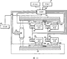
Figure 11 has shown the control system 200 of the cutting machine 10 of the preferred embodiment of the present invention.As detailed above, by be applied to the input of positioning motor 66 from programmable logic controller 68, it is controlled that each knife holder assemblies 56 moves to desirable position along upper and lower drive shaft device 44,46.Control system 200 comprises the upper and lower linear encoder 202 (Fig. 3 and 12) that a pair of and upper and lower drive shaft device 44,46 is relevant, it provides input to programmable logic controller 68, represents the position of each knife holder assemblies 56 along upper and lower drive shaft device 44,46.Each linear encoder 202 comprises one by elongated scale (scale) 204 and the scanning means 206 of upper and lower framework 26,28 supports, and each scanning means 206 is installed on the knife holder assemblies 56.Scanning means 206 is electrically connected with controller 68, and can operate and read the scale 208 (Fig. 3) that is set in each linear encoder 202 and provide the scale data to programmable logic controller 68, thereby the position controlled device of each knife holder assemblies 56 68 adopts closed-loop feedback manner to monitor and control.The linear encoder 202 that is suitable for cutting machine 10 of the present invention can be from Heidenhain Corporation of Schaumburg, and lllinois buys, though other linear encoder and other position detecting system also can be used.
Operate control system 200 of the present invention and can operate the relative vertical position of adjusting upper and lower rotary cutter 58.As detailed above, utilize jack screw motor 90 to actuate lift-bolt 86, control upper frame 26 is with respect to the pivoting action of fixing underframe 28.In order to achieve this end, the input that jack screw motor 90 receives from programmable logic controller 68 so that according to the operator by the input that HMI interface 70 is carried out, lift-bolt 86 extended or shrink.Transmitter 210 is installed on the cutting machine 10, and is electrically connected with programmable logic controller 68, and the input of the relative vertical position of the upper and lower rotary cutter 58 of expression is provided to controller 68.The data that programmable logic controller 68 uses transmitter 210 to be produced adopt the closed loop feedback control mode to monitor and adjust the relative vertical position of upper and lower cutter 58.
Figure 13 has shown a kind of master " cutter positioning program " 300, utilize control system 200 of the present invention, carry out main " cutter positioning program " 300, so that control the location of upper and lower knife holder assemblies 56 along upper and lower drive shaft device 44,46, according to principle of the present invention, adjust the relative perpendicular positioning of upper and lower cutter 58.As hereinafter describing in detail, main " cutter positioning program " 300 generally comprises 5 programs, comprise " input value program " 302, " self-triggered program " 304, " permissive check routine " 320, " position knives routine " 306 and " tool position audit program " 308, they are carried out by programmable logic controller 68 or HMI interface 70, guarantee that cutting machine 10 is provided with cutting machine automatically according to the data that the user imports by HMI interface 70.
More particularly,, utilize programmable logic controller 68 or HMI interface 70 original execution " input value program " 302, make the user import data or numerical value by HMI interface 70 in step 310 with reference to Figure 13.These numerical value comprise desirable 14 quantity, horizontal clearance percentage between the upper and lower cutter 58 of the desirable width of each bar, the thickness of sheet metal 12, desirable cooperation, the relative vertical position of desirable upper and lower rotary cutter 58 and desirable deviation distance apart from center line, in connotation of the present invention and scope, also can import other data.In step 312, HMI interface 70 determines whether that these input values are by predefined and be stored in the acceptable size range in the HMI interface 70.If the numerical value that the user imported is acceptable, in input value that step 310 received in step 314 is stored in programmable logic controller 68.Otherwise show an error message in step 316, alert operator, one or more numerical value that are transfused to exceed acceptable scope.The user enters step 310 then, continues by the numerical value of HMI interface 70 inputs in tolerance interval.
When " input value program " 302 receives acceptable numerical value and is stored in the programmable logic controller 68, controller 68 is carried out " self-triggered programs " 304, and it guarantees that cutting machine 10 locatees knife holder assemblies 56 in " input value program " 302 data of being imported automatically according to the user.Figure 14 has shown " self-triggered program " 304, and it comprises step 318, and in step 318, programmable logic controller 68 determines whether that " beginning automatically " button (not shown) opened or actuate by the user.It is user-operable button on a kind of user interface 72 that is positioned at cutting machine 10 that described " beginning automatically " button is positioned at, and when " beginning automatically " when button is operated, guarantees the data automatic setting that cutting machine is imported in step 310 according to the user.Be operated if " begin " button automatically, " self-triggered program " 304 carried out " permissive check routine " in step 320, and it checks the various conditions of cutting machine 10, guarantees that cutting machine 10 is compatibly operated.The term of execution of " the cutter positioning program " 300 of Fig. 1, " permissive check routine " 320 carried out continuously, will introduce in detail in conjunction with Figure 15 hereinafter.Otherwise,, then return " input value program " 302 shown in Figure 13 if determine that in step 318 " beginning automatically " button is not operated.
If by " permissive check routine " 320, indication cutting machine 10 is fit to operation, and in step 322, programmable logic controller 68 is guaranteed " beginning automatically " ability of cutting machine 10, and opens " non-attended light " (not shown) that is positioned at user interface 72." if permissive check routine " 320 failures, expression cutting machine 10 is not fit to operation, and in step 324, programmable logic controller 68 makes cutting machine 10 not have " beginning automatically " ability, and close " non-attended light ", " input value program " 302 shown in Figure 13 returned in control.
In conjunction with Figure 15, introduce 68 " permissive check routine of carrying out continuously " 320 of programmable logic controller." permissive check routine " 320 carried out different systems inspection in step 326~336, determines whether that cutting machine 10 is compatibly operated.Specifically, in step 326, programmable logic controller 68 determines whether that " promptly stopping " or " E stops " button (not shown) opened or actuate by the user." E stops " button is the user-operable button that is positioned on the cutting machine 10, when during " E stops " button, stopping all operations of cutting machine 10 such as operation in emergency circumstances immediately.If inoperation " E stops " button, controller 68 carry out to check in step 328, all function is normal to determine whether all communication systems of cutting machine 10.In step 330, programmable logic controller 68 determines whether that " stopping automatically " button (not shown) opened or actuate by the user, " stopping " button automatically is the manipulable button of user that is positioned on the user interface 72, when operation " stopping automatically " button, " beginning automatically " operation of cutting machine 10 can not be carried out, and closes " non-attended light ".
With reference to Figure 15, programmable logic controller 68 is carried out " tool motion collision routine " in step 332, determines whether that the motion of knife holder assemblies 56 will cause any two or more knife holder assemblies 56 to be collided each other, thereby cutting machine 10 is damaged.Hereinafter introduce " tool motion collision routine " 322 in detail in conjunction with Figure 16.In step 334, programmable logic controller 68 determines whether that cutter moves to their desirable positions along upper and lower drive unit 44,46, thereby finishes the motion of cutter.At the final step 336 of " permissive check routine " 320, programmable logic controller 68 is carried out " automatic dog program on duty ", determines whether control system 200 operation compatibly.Hereinafter will introduce " automatic dog program on duty " in conjunction with Figure 17 in detail.Failure at any one performed License Check of step 326~336 causes programmable logic controller 68 that cutting machine 10 " is begun " automatically, closes in step 338 " non-attended light ", and control turns back to " the input value program " of Figure 13.
With reference to Figure 16, performed " the tool motion collision routine " 332 of programmable logic controller 68 will be introduced.In step 340, the scale data (scale data) that the scanning means 206 of programmable logic controller 68 by linear encoder 202 provided monitor the motion and the position of each knife holder assemblies 56.In step 342, programmable logic controller 68 determines whether the motion of the knife holder assemblies 56 that causes at step 310 input value will cause any two or more knife holder assemblies 56 to be collided each other.If this occurs, in step 344, programmable logic controller 68 stops the motion of all knife holder assemblies that will collide each other 56, allows all other knife holder assemblies to continue to move to their desirable positions simultaneously.If determine that in step 342 all knife holder assemblies 56 do not bump each other, step 340 is returned in control.
Return Figure 17, will introduce programmable logic controller 68 performed " automatic dog program on duty ".In step 346, the scale data (scale data) that the scanning means 206 of controller 68 by linear encoder 202 provided monitor the motion and the position of each knife holder assemblies 56, in step 348, controller 68 determines whether each knife holder assemblies 56 has arrived its desirable position in the predetermined period of time in being stored in controller 68.If in step 348, any one knife holder assemblies 56 does not arrive desirable position in described predetermined period of time, and controller 68 is failed at step 350 demonstration License Check, and above-mentioned step 338 is returned in control.
Hereinafter be presented in performed " position knives routine " 306 of programmable logic controller during master's " cutter positioning program " 300 of Figure 12 68 in detail in conjunction with Figure 18." position knives routine " 306 is used for knife holder assemblies 56 is moved to their desirable positions in data that step 310 is imported according to the user.In step 352, controller 68 reads data that the user imports in step 310 and stores described data " entering data program " 302 (Figure 13) of step 314.In step 320, controller 68 is carried out in conjunction with Figure 15 described " permissive check routine ".If " permissive check routine " 320 passed through, controller 68 determines whether that in step 354 user has selected to make the center line operation of sheet metal 12 along cutting machine 10.If the user is at step 310 input one deviation value, controller 68 reads desirable deviation distance apart from the equipment center line in step 356.In step 358 and 360, controller 68 is determined the knife holder assemblies 56 necessary directions of motion, also the user is compared with the physical location of control system 200 determined knife holder assemblies 56 at desired all bars of step 310 input.
With reference to Figure 18, in step 362, controller 68 with all upper and lower knife holder assemblies 56 along upper and lower drive shaft device 44,46 to touch or stepping to their desirable positions fast.In step 320, controller 68 is carried out once more in conjunction with Figure 15 described " permissive check routine ".If " permissive check routine " 320 passed through, controller 68 step 364 determine whether upper and lower knife holder assemblies 56 along upper and lower drive shaft device 44,46 near they desirable positions, if not, controller 68 continues in step 366 upper and lower knife holder assemblies 56 to touch or stepping to their desirable positions fast, and " permissive check routine " 320 returned in control.If controller 68 step 364 determine one or more knife holder assemblies 56 along upper and lower drive shaft device 44,46 near they desirable positions, controller 68 touch or these knife holder assemblies 56 of stepping with than low velocity near their desirable positions, guarantee that knife holder assemblies 56 is very exactly near their desirable positions.In step 320, controller 68 is carried out once more in conjunction with Figure 15 described " permissive check routine ".If during carrying out " position knives routine " 306, " permissive check routine " 320 at any time failed, and in step 338, controller 68 can not " begin " cutting machine 10 automatically, close " non-attended light " (Figure 15), control program returns Figure 13 " input value program " 302.Adopt this mode, control system 200 moves to their desirable positions with knife holder assemblies 56 along upper and lower drive shaft device 44,46 fast, accurately and safely.
Hereinafter will be presented in performed " the tool position audit program " 308 of programmable logic controller during master's " cutter positioning program " 300 of Figure 12 68 in detail in conjunction with Figure 19.In step 370, controller 68 determines whether that each upper and lower knife holder assemblies 56 arrives its desirable position along upper and lower drive shaft device 44,46.If no, " position knives routine " 306 of Figure 18 returned in control, thereby as described in conjunction with " position knives routine " 306 of Figure 18, above-mentioned each remaining knife holder assemblies 56 is moved to their desirable positions.In step 372, import in step 310 for the user desirable 14, controller 68 determines whether that all knife holder assemblies 56 have arrived their desirable positions, if do not have, " position knives routine " 306 of Figure 18 returned in control once more, and it is desirable in conjunction with Figure 18 " position knives routine " 306 described positions that are used for desirable 14 thereby each residue knife holder assemblies 56 is moved to.
With reference to Figure 19, if desirable 14 of importing in step 310 for the user, all knife holder assemblies 56 are compatibly located along upper and lower drive shaft device 56, according to the vertical cutter location data that the user imports in step 310, controller 68 is actuated the relative vertical position that jack screw motor 90 is set up desirable upper and lower cutter 58 in step 374.In step 376, the data that controller 68 is produced by transmitter 210 (Figure 11), monitor the motion of lift-bolt 86, whether the relative vertical position of determining desirable upper and lower cutter 58 arrives, if no, step 374 is returned in control, the vertical cutter location data of importing in step 310 according to the user, controller 68 is actuated jack screw motor 90, to set up the relative vertical position of desirable upper and lower cutter 58.When the relative vertical position of desirable upper and lower cutter 58 arrived, " the input value program " of Figure 13 of step 310 returned in control.
Thereby, master's " cutter positioning program " by programmable logic controller 68 execution Figure 12, import the data that are fit to by the user by HMI interface 70, knife holder assemblies 56 can be by accurately, effectively and safely be positioned at upper and lower device framework 26 separately, in 28, the input data comprise desirable 14 quantity, each bar 14 desirable width, the material thickness of sheet material 12, the percentage of the horizontal clearance between the upper and lower cutter 58 of cooperation, the relative vertical position of upper and lower cutter 58 and desirable deviation distance apart from center line, in not breaking away from connotation scope of the present invention, also can import other numerical value.In programmable logic controller 68, described information is processed, and the instruction that is fit to is sent to each positioning motor 66, causes corresponding spherical nut 64 to rotate, thereby correctly locatees along 44,46 pairs of knife holder assemblies 56 of drive shaft device.Programmable logic controller 68 is also actuated jack screw motor 90, realizes upper and lower cutter 58 desirable relative vertical position, utilizes CNC cutting machine 10 of the present invention, avoids cutting machine 10 because hand control, dismounting and expansion caused downtime.
Below the present invention has been done very detailed description, thus after reading and having understood this specification, for a person skilled in the art, various changes of the present invention and revise and will become obvious.So all are so changed and correction is also included within this invention, so they are in the protection domain of claims.
Claims (26)
1, a kind of equipment of cutting sheet metal comprises:
Framework
Be installed in the last drive shaft device that rotates in this framework;
Be installed in the following drive shaft device that rotates in this framework;
Each upper and lower drive shaft device comprises a plurality of drive shaft section, and each drive shaft section is connected with the adjacent driven shaft portion rotating in framework by bindiny mechanism, and each bindiny mechanism is installed into a plurality of connected drive shaft section and rotates;
Operationally link to each other and be used to make the drive motor of described drive shaft device rotation with upper and lower drive shaft device;
It is right that interior and outer upper rail supports;
It is right that interior and outer lower guideway supports;
A plurality of in pairs by the knife holder assemblies of described frame supported to be used for moving along described drive shaft device, first knife holder assemblies is supported a pair of support of centering to move along last drive shaft device by interior and outer upper rail, and can be nested with the first adjacent knife holder assemblies, second knife holder assemblies is supported a pair of support of centering and moves with drive shaft device under the edge by interior and outer lower guideway, and can be nested with the second adjacent knife holder assemblies;
A plurality of rotary cutters, each cutter are installed on the knife holder assemblies and by a driving in the upper and lower drive shaft device;
Wherein, the cutter of first and second knife holder assemblies cooperatively interacts with to cutting by the sheet metal in gap between the cutter of corresponding cutters grip device;
The knife holder position regulating system is operably linked to each other with each knife holder assemblies, so that described knife holder assemblies is moved along the corresponding driving shaft device;
Programmable Logic Controller operationally links to each other with described knife holder position regulating system, along the corresponding driving shaft device knife holder assemblies is positioned.
2, equipment according to claim 1, wherein, framework also comprises:
Upper frame, last drive shaft device are installed in rotation on this upper frame;
The underframe that links to each other with described upper frame, following drive shaft device is installed in rotation on this underframe.
3, equipment according to claim 1, wherein, described knife holder position regulating system also comprises:
Be installed in the last thread spindle on the framework;
Be installed in the following thread spindle on the framework;
Wherein, each knife holder assemblies links to each other with a thread spindle screw thread, thereby the part of each knife holder assemblies makes this knife holder assemblies move along relevant drive shaft device with respect to the rotation of associated threads axle at least.
4, as equipment as described in the claim 3, wherein, described knife holder position regulating system also comprises:
A plurality of positioning motors, each positioning motor are installed on the knife holder assemblies and with Programmable Logic Controller and operationally link to each other; And
A plurality of spherical nuts, each spherical nut are installed on the knife holder assemblies, link to each other with a thread spindle screw thread, and operationally link to each other with the located in connection motor;
Utilize Programmable Logic Controller to drive each positioning motor, the associated ball nut is rotated, so that relevant knife holder assemblies is moved along the associated drives shaft device.
5, equipment according to claim 1, wherein, the position of each knife holder assemblies can be independent of other each knife holder assemblies by the knife holder position regulating system and adjust.
6, a kind of equipment of cutting sheet metal comprises:
Upper frame;
The underframe that links to each other with upper frame;
Be installed in the last drive shaft device that rotates in the upper frame, the described drive shaft device of going up comprises a plurality of drive shaft section that go up, drive shaft section is connected with adjacent last drive shaft section rotating in framework by last bindiny mechanism on each, and bindiny mechanism is installed into a plurality of connected drive shaft section that go up and rotates on each;
Be installed in the following drive shaft device that rotates in the underframe, described drive shaft device down comprises a plurality of drive shaft section down, each down drive shaft section is connected in framework, to rotate with adjacent following drive shaft section by bindiny mechanism down, each descends bindiny mechanism to be installed into a plurality of connected drive shaft section down and rotates;
Operationally link to each other and be used to make the drive motor of described drive shaft device rotation with upper and lower drive shaft device;
It is right that interior and outer upper rail supports;
It is right that interior and outer lower guideway supports;
A plurality of in pairs by the knife holder assemblies of moving of being used for of upper and lower frame supported along described drive shaft device, make the knife holder assemblies of winning be supported a pair of support of centering to move along last drive shaft device by interior and outer upper rail, and can be nested with the first adjacent knife holder assemblies, and second knife holder assemblies is moved with drive shaft device under the edge by a pair of support of interior and outer lower guideway support centering, and can be nested with the second adjacent knife holder assemblies;
A plurality of rotary cutters, each cutter are installed on the knife holder assemblies and by a driving in the upper and lower drive shaft device;
Wherein, the cutter of first and second knife holder assemblies cooperatively interacts with to cutting by the sheet metal in gap between the cutter of corresponding cutters grip device;
A plurality of positioning motors, each positioning motor are installed on the knife holder assemblies;
Be installed in the last thread spindle on the upper frame;
Be installed in the following thread spindle on the underframe;
A plurality of spherical nuts, each spherical nut are installed on the knife holder assemblies, link to each other with a thread spindle screw thread, and operationally link to each other with the located in connection motor;
Wherein, the part of each spherical nut makes this knife holder assemblies move along relevant drive shaft device with respect to the rotation of associated threads axle at least;
Programmable Logic Controller operationally links to each other with each positioning motor, along the corresponding driving shaft device knife holder assemblies is positioned;
Utilize Programmable Logic Controller to drive each positioning motor, the associated ball nut is rotated, so that the corresponding cutters grip device moves along the associated drives shaft device;
The position of each knife holder assemblies can be independent of other each knife holder assemblies and adjust.
7, a kind of equipment of cutting sheet metal comprises:
Framework;
Be installed in the last drive shaft device that rotates in this framework;
Be installed in the following drive shaft device that rotates in this framework;
Each drive shaft device comprises a plurality of drive shaft section, and each drive shaft section is connected with the adjacent driven shaft portion rotating in framework by bindiny mechanism, and each bindiny mechanism is installed into a plurality of connected drive shaft section and rotates;
Operationally link to each other and be used to make the drive motor of described drive shaft device rotation with upper and lower drive shaft device;
A plurality of in pairs by the knife holder assemblies of described frame supported to be used for moving along described drive shaft device, first knife holder assemblies is supported to move along last drive shaft device, and second knife holder assemblies is supported moves with drive shaft device under the edge;
A plurality of rotary cutters, each cutter are installed on the knife holder assemblies and by a driving in the upper and lower drive shaft device;
Wherein, the cutter of first and second knife holder assemblies cooperatively interacts with to cutting by the sheet metal in gap between the cutter of corresponding cutters grip device;
Wherein, adjacent each drive shaft section of each drive shaft device is suitable for optionally relative to each other reorientating, so that keep in repair described equipment.
8, as equipment as described in the claim 7, wherein:
Described bindiny mechanism links together adjacent drive shaft section releasedly.
9, as equipment as described in the claim 8, wherein, described bindiny mechanism is a shaft coupling, and each drive shaft section also comprises:
From the axially outstanding main shaft of drive shaft section, described shaft coupling connects the described main shaft on the adjacent driven shaft portion releasedly.
10, as equipment as described in the claim 7, also comprise:
Driving shaft is taken mechanism apart, is convenient to the user and selectively takes adjacent drive shaft section apart.
11, as equipment as described in the claim 10, wherein, driving shaft is taken mechanism apart and is comprised:
The screw rod that links to each other with at least one drive shaft section operationally,
In case described screw rod rotates, and axially recalls described drive shaft section from adjacent drive shaft section.
12, as equipment as described in the claim 7, wherein, adjacent drive shaft section is taken apart each other, is convenient to being arranged to a knife holder assemblies maintenance at contiguous adjacent driven shaft portion abutment.
13, a kind of equipment of cutting sheet metal comprises:
Framework;
Be installed in the last drive shaft device that rotates in this framework;
Be installed in the following drive shaft device that rotates in this framework;
Each drive shaft device comprises a plurality of drive shaft section, and each drive shaft section removably is connected to rotate in framework with the adjacent driven shaft portion;
From the axially outstanding main shaft of each drive shaft section,
The shaft coupling that main shaft on the adjacent driven shaft portion is linked together releasedly, each shaft coupling is mounted to described drive shaft section and rotates;
Operationally link to each other and be used to make the drive motor of described drive shaft device rotation with upper and lower drive shaft device;
A plurality of in pairs by the knife holder assemblies of described frame supported to be used for moving along described drive shaft device, first knife holder assemblies is supported to move along last drive shaft device, and second knife holder assemblies is supported moves with drive shaft device under the edge;
A plurality of rotary cutters, each cutter are installed on the knife holder assemblies and by a driving in the upper and lower drive shaft device;
Wherein, the cutter of first and second knife holder assemblies cooperatively interacts with to cutting by the sheet metal in gap between the cutter of corresponding cutters grip device;
Wherein, the adjacent driven shaft portion of each drive shaft device is suitable for taking apart each other selectively, is convenient to a knife holder assemblies that is configured to contiguous adjacent driven shaft portion abutment is keeped in repair; And
The screw rod that links to each other with at least one drive shaft section operationally;
In case described screw rod rotates, and axially withdraws from described drive shaft section from adjacent drive shaft section.
14, a kind of equipment of cutting sheet metal comprises:
Framework;
Be installed in the last drive shaft device that rotates in this framework;
Be installed in the following drive shaft device that rotates in this framework;
Each drive shaft device comprises a plurality of drive shaft section, and each drive shaft section is connected to rotate in framework with the adjacent driven shaft portion;
The shaft coupling that installation is used for releasedly the adjacent driven shaft portion being linked together and rotates with described drive shaft section;
Wherein, the adjacent driven shaft portion of each drive shaft device is suitable for taking apart each other selectively, is convenient to equipment is keeped in repair;
Operationally link to each other and be used to make the drive motor of described drive shaft device rotation with upper and lower drive shaft device;
A plurality of in pairs by the knife holder assemblies of described frame supported to be used for moving along described drive shaft device, first knife holder assemblies is supported to move along last drive shaft device, and second knife holder assemblies is supported moves with drive shaft device under the edge;
A plurality of rotary cutters, each cutter are installed on the knife holder assemblies and by a driving in the upper and lower drive shaft device;
Wherein, the cutter of first and second knife holder assemblies cooperatively interacts with to cutting by the sheet metal in gap between the cutter of corresponding cutters grip device;
The knife holder position regulating system is operably linked to each other with each knife holder assemblies, so that described knife holder assemblies is moved along the corresponding driving shaft device; And
Programmable Logic Controller operationally links to each other with described knife holder position regulating system, along the corresponding driving shaft device knife holder assemblies is positioned.
15, a kind of equipment of cutting sheet metal comprises:
Upper frame;
The underframe that links to each other with upper frame;
Be installed in the last drive shaft device that rotates in the upper frame, the described drive shaft device of going up comprises a plurality of drive shaft section that go up, drive shaft section is connected with adjacent last drive shaft section rotating in framework by last bindiny mechanism on each, and bindiny mechanism is installed into a plurality of connected drive shaft section that go up and rotates on each;
Be installed in the following drive shaft device that rotates in the underframe, described drive shaft device down comprises a plurality of drive shaft section down, each down drive shaft section is connected in framework, to rotate with adjacent following drive shaft section by bindiny mechanism down, each descends bindiny mechanism to be installed into a plurality of connected drive shaft section down and rotates;
Operationally link to each other and be used to make the drive motor of described drive shaft device rotation with upper and lower drive shaft device;
A plurality of in pairs by the knife holder assemblies of moving along described drive shaft device of being used for of upper and lower frame supported, first knife holder assemblies is supported moving along last drive shaft device, and second knife holder assemblies is supported to move along drive shaft device down;
A plurality of rotary cutters, each cutter are installed on the knife holder assemblies and by a driving in the upper and lower drive shaft device;
Wherein, the cutter of first and second knife holder assemblies cooperatively interacts with to cutting by the sheet metal in gap between the cutter of corresponding cutters grip device;
Wherein, upper frame is pivotally connected on the underframe by pivot, so that regulate the relative vertical position of the cutter of first and second knife holder assemblies, the sheet metal of different-thickness is cut.
16, as equipment as described in the claim 15, also comprise:
Frame adjustment mechanism is used for the relative vertical position at the cutter of axis direction adjusted first and second knife holder assemblies that are substantially perpendicular to drive shaft device.
17, as equipment as described in the claim 16, wherein, described frame adjustment mechanism also comprises:
A pair of lift-bolt, each screw rod is installed between upper frame and the underframe.
18, as equipment as described in the claim 17, also comprise:
With the actuator that each lift-bolt links to each other, be used for the synchronous adjustment of lift-bolt.
19, as equipment as described in the claim 15, wherein, keep between the framework parallel to each other when upper frame moves with respect to underframe.
20, as equipment as described in the claim 19, wherein, each goes up drive shaft device and following drive shaft device is setovered to described pivot relatively.
21, a kind of equipment of cutting sheet metal comprises:
Upper frame;
By pivot and the pivotally connected underframe of upper frame;
Be installed in the last drive shaft device that rotates in the upper frame, the described drive shaft device of going up comprises a plurality of drive shaft section that go up, drive shaft section is connected with adjacent last drive shaft section rotating in framework by last bindiny mechanism on each, and bindiny mechanism is installed into a plurality of connected drive shaft section that go up and rotates on each;
Be installed in the following drive shaft device that rotates in the underframe, described drive shaft device down comprises a plurality of drive shaft section down, each down drive shaft section is connected in framework, to rotate with adjacent following drive shaft section by bindiny mechanism down, each descends bindiny mechanism to be installed into a plurality of connected drive shaft section down and rotates;
Operationally link to each other and be used to make the drive motor of described drive shaft device rotation with upper and lower drive shaft device;
A plurality of in pairs by the knife holder assemblies of upper and lower frame supported on described drive shaft device, first knife holder assemblies is supported to move along last drive shaft device, and second knife holder assemblies is supported moves with drive shaft device under the edge;
A plurality of rotary cutters, each cutter are installed on the knife holder assemblies and by a driving in the upper and lower drive shaft device;
Wherein, the cutter of first and second knife holder assemblies cooperatively interacts with to cutting by the sheet metal in gap between the cutter of corresponding cutters grip device;
A pair of lift-bolt, each is installed between upper frame and the underframe, be used for relative vertical position, the sheet metal of different-thickness is cut at the cutter of axis direction adjusted first and second knife holder assemblies that are substantially perpendicular to drive shaft device;
Keep between the framework parallel to each other when wherein, upper frame moves with respect to underframe;
With the actuator that each lift-bolt links to each other, be used for lift-bolt and adjust synchronously.
22, a kind of equipment of cutting sheet metal comprises:
Upper frame;
The underframe that links to each other with upper frame;
Be installed in the last drive shaft device that rotates in the upper frame, the described drive shaft device of going up comprises a plurality of drive shaft section that go up, drive shaft section is connected with adjacent last drive shaft section rotating in framework by last bindiny mechanism on each, and bindiny mechanism is installed into a plurality of connected drive shaft section that go up and rotates on each;
Be installed in the following drive shaft device that rotates in the underframe, described drive shaft device down comprises a plurality of drive shaft section down, each down drive shaft section is connected in framework, to rotate with adjacent following drive shaft section by bindiny mechanism down, each descends bindiny mechanism to be installed into a plurality of connected drive shaft section down and rotates;
Operationally link to each other and be used to make the drive motor of described drive shaft device rotation with upper and lower drive shaft device;
A plurality of in pairs by the knife holder assemblies of upper and lower frame supported on described drive shaft device, first knife holder assemblies is supported to move along last drive shaft device, and second knife holder assemblies is supported moves with drive shaft device under the edge;
A plurality of rotary cutters, each cutter are installed on the knife holder assemblies and by a driving in the upper and lower drive shaft device;
Wherein, the cutter of first and second knife holder assemblies cooperatively interacts with to cutting by the sheet metal in gap between the cutter of corresponding cutters grip device;
The knife holder position regulating system is operably linked to each other with each knife holder assemblies, so that described knife holder assemblies is moved along the corresponding driving shaft device;
Programmable Logic Controller operationally links to each other with described knife holder position regulating system, along the corresponding driving shaft device knife holder assemblies is positioned;
Wherein, upper frame is connected in underframe by the pivot pivot with adorning, so that regulate the relative vertical position of the cutter of first and second knife holder assemblies, the sheet metal of different-thickness is cut.
23, a kind of equipment of cutting sheet metal comprises:
Upper frame;
The underframe that links to each other with upper frame;
Be installed in the last drive shaft device that rotates in the upper frame;
Be installed in the following drive shaft device that rotates in the underframe;
Each drive shaft device comprises a plurality of drive shaft section, and each drive shaft section links to each other releasedly with adjacent drive shaft section, so that rotate in relevant framework;
The shaft coupling that releasedly the adjacent driven shaft portion is linked together and rotate with described drive shaft section;
Operationally link to each other and be used to make the drive motor of described drive shaft device rotation with upper and lower drive shaft device;
A plurality of in pairs by the knife holder assemblies of described frame supported to be used for moving along described drive shaft device, first knife holder assemblies is supported to move along last drive shaft device, and second knife holder assemblies is supported moves with drive shaft device under the edge;
A plurality of rotary cutters, each cutter are installed on the knife holder assemblies and by a driving in the upper and lower drive shaft device;
Wherein, the cutter of first and second knife holder assemblies cooperatively interacts with to cutting by the sheet metal in gap between the cutter of corresponding cutters grip device;
Wherein, the adjacent drive shaft section of each drive shaft device is suitable for taking apart each other selectively, so that equipment is keeped in repair;
Wherein, upper frame can move with respect to underframe, so that regulate the relative vertical position of the cutter of first and second knife holder assemblies, the sheet metal of different-thickness is cut.
24, a kind of equipment of cutting sheet metal comprises:
Upper frame;
The underframe that links to each other with upper frame;
Be installed in the last drive shaft device that rotates in the upper frame;
Be installed in the following drive shaft device that rotates in the underframe;
Each drive shaft device comprises a plurality of drive shaft section, and each drive shaft section links to each other releasedly with adjacent drive shaft section, so that rotate in respective frame;
Wherein, the drive shaft section that each drive shaft device is adjacent is suitable for taking apart each other selectively, so that equipment is keeped in repair;
Operationally link to each other and be used to make the drive motor of described drive shaft device rotation with upper and lower drive shaft device;
A plurality of in pairs by the knife holder assemblies of described frame supported to be used for moving along described drive shaft device, first knife holder assemblies is supported to move along last drive shaft device, and second knife holder assemblies is supported moves with drive shaft device under the edge;
A plurality of rotary cutters, each cutter are installed on the knife holder assemblies and by a driving in the upper and lower drive shaft device;
Wherein, the cutter of first and second knife holder assemblies cooperatively interacts with to cutting by the sheet metal in gap between the cutter of corresponding cutters grip device;
Wherein, upper frame is connected in underframe by the pivot pivot with adorning, so that adjust the relative vertical position of the cutter of first and second knife holder assemblies, the sheet metal of different-thickness is cut;
The knife holder position regulating system is operably linked to each other with each knife holder assemblies, so that described knife holder assemblies is moved along the corresponding driving shaft device;
Programmable Logic Controller operationally links to each other with described knife holder position regulating system, along the corresponding driving shaft device knife holder assemblies is positioned.
25, a kind of equipment of cutting sheet metal comprises:
Framework;
Be installed in the last drive shaft device that rotates in this framework, the described drive shaft device of going up comprises a plurality of drive shaft section that go up, drive shaft section is connected with adjacent last drive shaft section rotating in framework by last bindiny mechanism on each, and bindiny mechanism is installed into a plurality of connected drive shaft section that go up and rotates on each;
Be installed in the following drive shaft device that rotates in this framework, described drive shaft device down comprises a plurality of drive shaft section down, each down drive shaft section is connected in framework, to rotate with adjacent following drive shaft section by bindiny mechanism down, each descends bindiny mechanism to be installed into a plurality of connected drive shaft section down and rotates;
Operationally link to each other and be used to make the drive motor of described drive shaft device rotation with upper and lower drive shaft device;
It is right that interior and outer upper rail supports;
It is right that interior and outer lower guideway supports;
A plurality of in pairs by the knife holder assemblies of described frame supported to be used for moving along described drive shaft device, make the knife holder assemblies of winning be supported a pair of support of centering to move along last drive shaft device by interior and outer upper rail, and can be nested with the first adjacent knife holder assemblies, and second knife holder assemblies is moved with drive shaft device under the edge by a pair of support of interior and outer lower guideway support centering, and can be nested with the second adjacent knife holder assemblies;
A plurality of rotary cutters, each cutter are installed on the knife holder assemblies and by a driving in the upper and lower drive shaft device;
Wherein, the cutter of first and second knife holder assemblies cooperatively interacts with to cutting by the sheet metal in gap between the cutter of corresponding cutters grip device;
The knife holder position adjusting device makes each knife holder assemblies move along the corresponding driving shaft device;
Be used to control the control device of described knife holder position adjusting device.
26, a kind of equipment of cutting sheet metal comprises:
Upper frame;
The underframe that pivots and be connected by pivot and upper frame;
Be installed in the last drive shaft device that rotates in the upper frame, the described drive shaft device of going up comprises a plurality of drive shaft section that go up, drive shaft section is connected with adjacent last drive shaft section rotating in framework by last bindiny mechanism on each, and bindiny mechanism is installed into a plurality of connected drive shaft section that go up and rotates on each;
Be installed in the following drive shaft device that rotates in the underframe, described drive shaft device down comprises a plurality of drive shaft section down, each down drive shaft section is connected in framework, to rotate with adjacent following drive shaft section by bindiny mechanism down, each descends bindiny mechanism to be installed into a plurality of connected drive shaft section down and rotates;
Operationally link to each other and be used to make the drive motor of described drive shaft device rotation with upper and lower drive shaft device;
A plurality of in pairs by the knife holder assemblies of moving along described drive shaft device of being used for of upper and lower frame supported, first knife holder assemblies is supported moving along last drive shaft device, and second knife holder assemblies is supported to move along drive shaft device down;
A plurality of rotary cutters, each cutter are installed on the knife holder assemblies and by a driving in the upper and lower drive shaft device;
Wherein, the cutter of first and second knife holder assemblies cooperatively interacts with to cutting by the sheet metal in gap between the cutter of corresponding cutters grip device;
Frame moving device is used to make upper frame to move with respect to underframe, adjusts the relative vertical position of the cutter of first and second knife holder assemblies, and the sheet metal of different-thickness is cut.
Applications Claiming Priority (2)
| Application Number | Priority Date | Filing Date | Title |
|---|---|---|---|
| US10/008,936 US7134372B2 (en) | 2001-11-08 | 2001-11-08 | CNC slitter machine |
| US10/008,936 | 2001-11-08 |
Publications (2)
| Publication Number | Publication Date |
|---|---|
| CN1610591A CN1610591A (en) | 2005-04-27 |
| CN100352585C true CN100352585C (en) | 2007-12-05 |
Family
ID=21734577
Family Applications (1)
| Application Number | Title | Priority Date | Filing Date |
|---|---|---|---|
| CNB028265718A Expired - Fee Related CN100352585C (en) | 2001-11-08 | 2002-11-04 | CNC web slitter machine |
Country Status (8)
| Country | Link |
|---|---|
| US (1) | US7134372B2 (en) |
| EP (1) | EP1458512B1 (en) |
| JP (1) | JP4413613B2 (en) |
| CN (1) | CN100352585C (en) |
| AT (1) | ATE337879T1 (en) |
| CA (1) | CA2466330C (en) |
| DE (1) | DE60214425T2 (en) |
| WO (1) | WO2003039795A1 (en) |
Families Citing this family (43)
| Publication number | Priority date | Publication date | Assignee | Title |
|---|---|---|---|---|
| US20060074499A1 (en) * | 2004-10-01 | 2006-04-06 | Rafie Hamidpour | System and method for industrial process control |
| DE202005014838U1 (en) * | 2005-09-21 | 2005-11-17 | DIENES WERKE FüR MASCHINENTEILE GMBH & CO. KG | Slitter, has shifting unit that engages at upper and lower cutters using extendable and supporting linear track, such that cutters are shifted together by unit, and guiding device arranged form-fittingly centering in receptacle |
| US20070101846A1 (en) * | 2005-11-07 | 2007-05-10 | Zahn Lloyd P | Compensating stripper rings for material slitting machines |
| US8210079B2 (en) * | 2007-09-14 | 2012-07-03 | L&P Property Management Company | Programmable border slitter |
| CA2643552A1 (en) * | 2007-11-09 | 2009-05-09 | Sms Demag Ltd. | Slitter line knife holder assembly |
| CA2643554A1 (en) * | 2007-11-09 | 2009-05-09 | Sms Demag Ltd. | Slitting machine |
| US20090297323A1 (en) * | 2008-05-30 | 2009-12-03 | Genesis Worldwide Ii, Inc. | Method and apparatus for stacking sheet materials |
| US7992604B1 (en) * | 2008-07-08 | 2011-08-09 | Stiles Machinery, Inc. | Ripsaw stabilizing device |
| DE102010002271B4 (en) * | 2010-02-24 | 2012-05-31 | Mag Ias Gmbh | Cutting device for shearing fiber strands |
| US8312798B2 (en) * | 2010-05-18 | 2012-11-20 | Eastman Kodak Company | Slitter with translating cutting devices |
| CN102059394A (en) * | 2010-12-01 | 2011-05-18 | 河南东力重工机械有限公司 | Numerical control metal plate dividing and shearing device |
| AT511200B1 (en) * | 2011-10-20 | 2012-10-15 | Isiqiri Interface Tech Gmbh | REAL TIME MEASUREMENT OF RELATIVE POSITION DATA AND / OR GEOMETRIC MASSES OF A MOVING BODY USING OPTICAL MEASURING AGENTS |
| US8875608B2 (en) * | 2011-11-07 | 2014-11-04 | Lasermax Roll Systems, Inc. | Sheet slitting mechanism with automated size adjustment |
| US8869668B1 (en) * | 2011-11-18 | 2014-10-28 | Hormel Foods Corporation | Product cutter |
| CN102570246B (en) * | 2012-01-12 | 2014-01-01 | 苏州市金松精密电子有限公司 | Doubled-thread cutting device |
| US8813622B2 (en) * | 2012-02-10 | 2014-08-26 | Red Bud Industries, Inc. | Machine for slitting metal sheet |
| US9138905B2 (en) * | 2013-02-22 | 2015-09-22 | Valmet Technologies, Inc. | Method for calibrating the position of the slitter blades of a slitter-winder |
| US20140260868A1 (en) * | 2013-03-15 | 2014-09-18 | Dienes Corporation Usa | Slitting Machine |
| CN103332522B (en) * | 2013-05-16 | 2016-09-28 | 何春明 | The longitudinal cutting device of paper cutter and control method thereof |
| CH708130A1 (en) * | 2013-05-31 | 2014-12-15 | Can Man Ag | Scissors for making sheet metal blanks made of metal sheets or metal strips. |
| CN103394749A (en) * | 2013-07-26 | 2013-11-20 | 江苏亨特宏业重工有限公司 | Width adjusting device for disc shearing unit |
| CN104552391A (en) * | 2013-10-28 | 2015-04-29 | 中船华南船舶机械有限公司 | Cutter clamping device |
| CN103567531B (en) * | 2013-11-14 | 2016-05-25 | 阿博建材(昆山)有限公司 | There is muscle net cutting device |
| DE102013113421A1 (en) * | 2013-12-04 | 2015-06-11 | Manroland Web Systems Gmbh | Längsschnittmessernachführung |
| CN105035824B (en) * | 2015-05-28 | 2017-06-06 | 欣龙控股(集团)股份有限公司 | A kind of 3.5 meters of cutting machine reeling-off tension control systems of movable type |
| CN105397170B (en) * | 2015-11-30 | 2018-02-13 | 郑州金泰制罐有限公司 | A kind of metal sheet surface trimming production line |
| CN105364162B (en) * | 2015-12-07 | 2017-08-08 | 湖北天利化建工程有限公司 | A kind of automatic break down device |
| CN106077792B (en) * | 2016-06-28 | 2018-02-09 | 佛山市三水艺辉印铁制罐有限公司 | A kind of cutter for automatically adjusting cutter location |
| JP6927574B2 (en) * | 2016-09-21 | 2021-09-01 | デュプロ精工株式会社 | Slitters, sheet cutting machines, and sheet processing equipment |
| JP6872218B2 (en) * | 2016-09-21 | 2021-05-19 | デュプロ精工株式会社 | Sheet processing equipment |
| CN106586654B (en) * | 2017-02-28 | 2018-03-06 | 重庆市逸琨电子科技有限公司 | A kind of adjustable adhesive tape cutting machine |
| CN108687850A (en) * | 2017-04-07 | 2018-10-23 | 友聚工业有限公司 | Banding machine |
| CN107297533A (en) * | 2017-06-01 | 2017-10-27 | 惠州市瑰拉科技有限公司 | Aluminium sheet cutting machine |
| CN107225280A (en) * | 2017-07-18 | 2017-10-03 | 大英德创精工设备有限公司 | Cold cut machine with leads pinch resistant functionality |
| CN107175363A (en) * | 2017-07-18 | 2017-09-19 | 大英德创精工设备有限公司 | Cold cut machine with leads guide function |
| DE102017117524A1 (en) * | 2017-08-02 | 2019-02-07 | DIENES WERKE FüR MASCHINENTEILE GMBH & CO. KG | Knife holder with adjusting slide |
| DE102017117537A1 (en) * | 2017-08-02 | 2019-02-07 | Moto Industries Co., Ltd. | cutting machine |
| CA3043783C (en) * | 2018-05-16 | 2021-04-20 | Usnr, Llc | Splitter profiler |
| CN108890036B (en) * | 2018-07-08 | 2020-03-06 | 兰溪金工钢结构工程有限公司 | Steel cutting device convenient to dismantle and maintain |
| PL431950A1 (en) * | 2019-11-26 | 2021-05-31 | Grafotronic Spółka Z Ograniczoną Odpowiedzialnością | System for positioning the tool on the shaft and device for cutting the web containing such system |
| JP7449719B2 (en) * | 2020-02-28 | 2024-03-14 | 三菱重工機械システム株式会社 | Slitter device, slitter head positioning method, and box making machine |
| CN111570897B (en) * | 2020-05-14 | 2022-11-08 | 中能建(北京)能源研究院有限公司 | Lithium battery pole piece slitting equipment |
| CN113524301A (en) * | 2021-07-26 | 2021-10-22 | 重庆凯丰医疗器械有限公司 | Non-woven fabrics automatic cutting device who pastes is treated in TDP moxibustion in special use |
Citations (4)
| Publication number | Priority date | Publication date | Assignee | Title |
|---|---|---|---|---|
| DE2714325A1 (en) * | 1977-03-31 | 1978-10-12 | Kampf Maschf Erwin | DEVICE FOR SEPARATING FILMS OR TAPES |
| US4684360A (en) * | 1985-02-14 | 1987-08-04 | Rengo Co., Ltd. | Tool positioning device |
| US4887502A (en) * | 1986-12-08 | 1989-12-19 | Red Bud Industries, Inc. | Machine for slitting metal sheet |
| US5669279A (en) * | 1994-12-23 | 1997-09-23 | Sms Schloemann-Siemag Aktiengesellschaft | Shearing machine for trimming flat material particularly sheets and strips of metal |
Family Cites Families (26)
| Publication number | Priority date | Publication date | Assignee | Title |
|---|---|---|---|---|
| US3003403A (en) * | 1959-11-03 | 1961-10-10 | Samuel M Langston Co | Mechanism for reducing set-up time and maintenance of slotting, scoring, slitting and lap cutting apparatus |
| US3570335A (en) * | 1969-03-17 | 1971-03-16 | Pitney Bowes Inc | Cam actuated paperworking assembly for folding machines |
| US3886833A (en) * | 1974-05-01 | 1975-06-03 | Elworthy & Co Ltd | Apparatus to effect remote automatic positioning of web slitter |
| US4102227A (en) * | 1976-05-03 | 1978-07-25 | Ppg Industries, Inc. | Method of and apparatus for aligning a scoring wheel with a support wheel |
| CA1076020A (en) | 1977-10-20 | 1980-04-22 | Rengo Co. | Tool positioning apparatus |
| JPS54108989A (en) * | 1978-02-15 | 1979-08-27 | Sumikura Kogyo Kk | Automatic edge tool positioning device of slitter |
| US4226150A (en) | 1978-08-15 | 1980-10-07 | Avery International Corporation | Deflectable bearer roll |
| US4201352A (en) * | 1978-09-25 | 1980-05-06 | Loopco Industries, Inc. | Method and combination for winding strands of web material having varying thicknesses on a take-up drum |
| SE416278B (en) * | 1979-03-22 | 1980-12-15 | Foerenade Fabriksverken | METHOD AND DEVICE FOR SETTING ROLLING RINGS ON AN AXLE |
| US4254677A (en) | 1979-11-05 | 1981-03-10 | Molins Machine Company, Inc. | Slitter blade positioning means |
| US4346635A (en) * | 1979-11-05 | 1982-08-31 | Loopco Industries, Inc. | Slitter with removable head |
| CA1180428A (en) * | 1980-11-13 | 1985-01-02 | Masateru Tokuno | Method and apparatus for positioning tools |
| JPS59169749A (en) * | 1983-03-15 | 1984-09-25 | Rengo Co Ltd | Tool positioning method |
| US4627214A (en) * | 1985-09-23 | 1986-12-09 | Marquip, Inc. | Slitting-scoring machine |
| DE3811953A1 (en) | 1987-04-23 | 1988-11-03 | Schloemann Siemag Ag | Slitting strip shears |
| IT1222982B (en) * | 1987-10-23 | 1990-09-12 | Elio Cavagna | CONTROL UNIT FOR THE BIDIRECTIONAL TRANSLATION OF KNIVES AND COUNTER KNIVES INTO A MACHINE FOR THE CUTTING OF SUBSTANTIALLY PAPER TYPE OF MATERIAL |
| GB2226513B (en) * | 1988-11-29 | 1992-04-08 | Senior Bigwood Limited | Tube weld mill |
| US5036741A (en) * | 1990-10-01 | 1991-08-06 | Piw Industries, Inc. | Saw apparatus with saw collar positioning means |
| US5325751A (en) * | 1993-02-17 | 1994-07-05 | Mereen-Johnson Machine Company | Gang rip saw assembly |
| JP3581189B2 (en) * | 1995-04-28 | 2004-10-27 | 株式会社イソワ | Slitter sheet receiving device |
| DE19518457A1 (en) * | 1995-05-19 | 1996-11-21 | Robel Georg Gmbh & Co | Device for grinding rails |
| US5637068A (en) * | 1995-07-07 | 1997-06-10 | U.S. Natural Resources, Inc. | Method and apparatus for changing a saw assembly |
| DE19603361C2 (en) * | 1996-01-31 | 2000-10-12 | Fischer G Rohrverbindungstech | Pipe cutting and pipe chamfering device for a thin-walled pipe |
| EP0842905A4 (en) * | 1996-05-13 | 1999-11-10 | Bando Kiko Co | Apparatus for processing glass sheet |
| US5899319A (en) * | 1996-10-09 | 1999-05-04 | Farmers Rice Milling Company, Inc. | Coupling and process for screw conveyors |
| DE19816179C1 (en) * | 1998-04-14 | 1999-11-11 | Fischer G Rohrverbindungstech | Machining apparatus for tube ends |
-
2001
- 2001-11-08 US US10/008,936 patent/US7134372B2/en not_active Expired - Lifetime
-
2002
- 2002-11-04 JP JP2003541676A patent/JP4413613B2/en not_active Expired - Lifetime
- 2002-11-04 CN CNB028265718A patent/CN100352585C/en not_active Expired - Fee Related
- 2002-11-04 AT AT02776446T patent/ATE337879T1/en not_active IP Right Cessation
- 2002-11-04 EP EP02776446A patent/EP1458512B1/en not_active Expired - Lifetime
- 2002-11-04 DE DE60214425T patent/DE60214425T2/en not_active Expired - Lifetime
- 2002-11-04 CA CA002466330A patent/CA2466330C/en not_active Expired - Fee Related
- 2002-11-04 WO PCT/US2002/035337 patent/WO2003039795A1/en active IP Right Grant
Patent Citations (4)
| Publication number | Priority date | Publication date | Assignee | Title |
|---|---|---|---|---|
| DE2714325A1 (en) * | 1977-03-31 | 1978-10-12 | Kampf Maschf Erwin | DEVICE FOR SEPARATING FILMS OR TAPES |
| US4684360A (en) * | 1985-02-14 | 1987-08-04 | Rengo Co., Ltd. | Tool positioning device |
| US4887502A (en) * | 1986-12-08 | 1989-12-19 | Red Bud Industries, Inc. | Machine for slitting metal sheet |
| US5669279A (en) * | 1994-12-23 | 1997-09-23 | Sms Schloemann-Siemag Aktiengesellschaft | Shearing machine for trimming flat material particularly sheets and strips of metal |
Also Published As
| Publication number | Publication date |
|---|---|
| DE60214425D1 (en) | 2006-10-12 |
| US7134372B2 (en) | 2006-11-14 |
| EP1458512A1 (en) | 2004-09-22 |
| JP4413613B2 (en) | 2010-02-10 |
| ATE337879T1 (en) | 2006-09-15 |
| CA2466330C (en) | 2007-06-12 |
| US20030205117A1 (en) | 2003-11-06 |
| CA2466330A1 (en) | 2003-05-15 |
| WO2003039795A1 (en) | 2003-05-15 |
| CN1610591A (en) | 2005-04-27 |
| DE60214425T2 (en) | 2007-10-11 |
| EP1458512B1 (en) | 2006-08-30 |
| JP2005508260A (en) | 2005-03-31 |
Similar Documents
| Publication | Publication Date | Title |
|---|---|---|
| CN100352585C (en) | CNC web slitter machine | |
| DE3223231C2 (en) | Automatic tracking device and method for automatic tracking of a work image | |
| US10871758B2 (en) | Plasma processing long steel product including beams | |
| US4878524A (en) | Woodworking machine having a plurality of sequentially operative multiple tool units | |
| CA1290241C (en) | Machine for slitting metal sheet | |
| US4016856A (en) | Wire cutting machine | |
| JPS60259398A (en) | Method of controlling position of cutting blade in vertical cutter for paper web, etc. | |
| WO2016008986A1 (en) | Method for operating a belt grinding device | |
| CA1271125A (en) | Machine for slitting continuous tapes into stripes, in particular with cutting cylinders having variable size | |
| EP1612012B1 (en) | Slitting knife cartridge | |
| US3545326A (en) | Swing type arbor attachment for quick tool changes | |
| CN202019129U (en) | Numerical control precision spigot end module | |
| US20050229762A1 (en) | Cnc slitter machine | |
| DE4113543A1 (en) | Machine for trimming edges of sheets - has coaxial probe roller attached to cutting tool to make cutter operate when roller meets surface of lipping to be dressed off flush | |
| EP1063057B1 (en) | Grinding wheel dressing apparatus | |
| CN109773596A (en) | A kind of sintered carbide tools grinding machine | |
| CA2070780C (en) | Supporting apparatus | |
| CN108838683B (en) | Full-automatic curve bending processing equipment | |
| CN201350513Y (en) | Multi-cutter numerical control boring lathe for boring | |
| DE19845284B4 (en) | Conicity correction device for a grinding machine | |
| DE102014016404B4 (en) | Tape laying machine | |
| JP2022536897A (en) | Cutting machine for paper rolls with grinding device | |
| DE102020205088A1 (en) | Method and evaluation system for monitoring tool wear on tool components in machining production plants | |
| CN201376049Y (en) | Roll riveting device on cross flow fan roll riveting forming machine | |
| CN216442052U (en) | Numerical control lathe with automatic clamping function |
Legal Events
| Date | Code | Title | Description |
|---|---|---|---|
| C06 | Publication | ||
| PB01 | Publication | ||
| C10 | Entry into substantive examination | ||
| SE01 | Entry into force of request for substantive examination | ||
| C14 | Grant of patent or utility model | ||
| GR01 | Patent grant | ||
| C17 | Cessation of patent right | ||
| CF01 | Termination of patent right due to non-payment of annual fee |
Granted publication date: 20071205 Termination date: 20101104 |