CN100348148C - Temperature measuring and transmitter/receiver device - Google Patents
Temperature measuring and transmitter/receiver device Download PDFInfo
- Publication number
- CN100348148C CN100348148C CNB2004100752599A CN200410075259A CN100348148C CN 100348148 C CN100348148 C CN 100348148C CN B2004100752599 A CNB2004100752599 A CN B2004100752599A CN 200410075259 A CN200410075259 A CN 200410075259A CN 100348148 C CN100348148 C CN 100348148C
- Authority
- CN
- China
- Prior art keywords
- temperature measuring
- temperature
- cognizance code
- described temperature
- data
- Prior art date
- Legal status (The legal status is an assumption and is not a legal conclusion. Google has not performed a legal analysis and makes no representation as to the accuracy of the status listed.)
- Expired - Fee Related
Links
Images


Classifications
-
- G—PHYSICS
- G01—MEASURING; TESTING
- G01K—MEASURING TEMPERATURE; MEASURING QUANTITY OF HEAT; THERMALLY-SENSITIVE ELEMENTS NOT OTHERWISE PROVIDED FOR
- G01K1/00—Details of thermometers not specially adapted for particular types of thermometer
- G01K1/02—Means for indicating or recording specially adapted for thermometers
- G01K1/024—Means for indicating or recording specially adapted for thermometers for remote indication
-
- A—HUMAN NECESSITIES
- A61—MEDICAL OR VETERINARY SCIENCE; HYGIENE
- A61B—DIAGNOSIS; SURGERY; IDENTIFICATION
- A61B5/00—Measuring for diagnostic purposes; Identification of persons
- A61B5/01—Measuring temperature of body parts ; Diagnostic temperature sensing, e.g. for malignant or inflamed tissue
-
- G—PHYSICS
- G01—MEASURING; TESTING
- G01K—MEASURING TEMPERATURE; MEASURING QUANTITY OF HEAT; THERMALLY-SENSITIVE ELEMENTS NOT OTHERWISE PROVIDED FOR
- G01K13/00—Thermometers specially adapted for specific purposes
- G01K13/20—Clinical contact thermometers for use with humans or animals
-
- G—PHYSICS
- G01—MEASURING; TESTING
- G01K—MEASURING TEMPERATURE; MEASURING QUANTITY OF HEAT; THERMALLY-SENSITIVE ELEMENTS NOT OTHERWISE PROVIDED FOR
- G01K7/00—Measuring temperature based on the use of electric or magnetic elements directly sensitive to heat ; Power supply therefor, e.g. using thermoelectric elements
- G01K7/16—Measuring temperature based on the use of electric or magnetic elements directly sensitive to heat ; Power supply therefor, e.g. using thermoelectric elements using resistive elements
- G01K7/22—Measuring temperature based on the use of electric or magnetic elements directly sensitive to heat ; Power supply therefor, e.g. using thermoelectric elements using resistive elements the element being a non-linear resistance, e.g. thermistor
-
- G—PHYSICS
- G08—SIGNALLING
- G08B—SIGNALLING OR CALLING SYSTEMS; ORDER TELEGRAPHS; ALARM SYSTEMS
- G08B21/00—Alarms responsive to a single specified undesired or abnormal condition and not otherwise provided for
- G08B21/02—Alarms for ensuring the safety of persons
-
- G—PHYSICS
- G01—MEASURING; TESTING
- G01K—MEASURING TEMPERATURE; MEASURING QUANTITY OF HEAT; THERMALLY-SENSITIVE ELEMENTS NOT OTHERWISE PROVIDED FOR
- G01K2215/00—Details concerning sensor power supply
Abstract
This temperature measurement transceiver is combined with an antenna 18 for supplying a radio wave, an RF driver 16, an RF receiving circuit 17 for receiving a radio output and a temperature measuring transceiver provided with a liquid crystal display part 13, in a temperature measurement transceiver with an antenna 22 for receiving the radio wave, an electric power generation circuit 27 for conducting self-excitation power generation by rectifying the radio wave received by the antenna 22, a temperature sensor 25, and an RF part 21. To realize high temperature detecting precision required in a clinical thermometer, to shorten a measuring time, to accurately record temperature-detected data, and to finish storage work as a data.
Description
Technical field
The present invention, relate to a kind of can be correctly and easily carry out by thermometric person's measurement of bldy temperature, and the temperature measuring and transmitting device of the person's that alleviates the thermometric burden.
Background technology
Be directly connected to body temperature of keeping, heart rate, breathing, blood pressure of life etc., be generically and collectively referred to as vital signs (vital sign) especially, if vital signs are stable down in certain value (normal value), can think that the control of life runs well, otherwise, can learn not to be the normal healthy state if unstable.Therefore, as hospital, the necessity of the daily patient's of being admitted to hospital body temperature being carried out measurement of bldy temperature is arranged.
[patent documentation 1] spy opens flat 11-113856 communique
[patent documentation 2] special table 2002-512829 communique
Use the hydrargyrum formula, perhaps any one of electronic type clinical thermometer, the nurse goes the rounds in preset time, the patient distributes clinical thermometer to being admitted to hospital, the patient oneself that is admitted to hospital is clipped in the oxter to clinical thermometer, the nurse is touring again after the certain hour regains clinical thermometer from the patient that respectively is admitted to hospital, and reads temperature-measuring results, notes down on minute book.Also have, after having gone the rounds all patients, the clinical thermometer of all recovery is carried out disinfection, and be necessary the described temperature-measuring results that is recorded on the minute book is input in the computer.
But, the problem below in above-mentioned background technology, can taking place.
In most of hospital, for the patient's that is admitted to hospital health status is confirmed one by one, every day the early, middle and late measurement of bldy temperature that carries out 3 times.Usually, all patients that are admitted to hospital are carried out measurement of bldy temperature, obtain temperature data, and it is carried out record.
The hydrargyrum formula thermometer that is used for take temperature, when measuring temperature, need expend very many time, and the electronic type clinical thermometer is in order to shorten the time of take temperature, mostly be forecasting type greatly, because final stable equilibrium temperature is inferred, if itself and skin are adjacent to, may produce than mistake.
The work of record must be by name, body temperature, the order of time on date (time), with pencil etc., all patient's data are correctly carried out record.In the work of take temperature, the work of additional this record simultaneously, nurse one side as measuring temperature has become a kind of numerous and diverse work.In addition, as patient one side that is admitted to hospital of measured temperature, also become a kind of work of taking great energy very much simultaneously.
As the work of measuring temperature record in addition, to each patient, body temperature with 3 times on the 1st records, also be kept in the computer as historical record with the mode of electronic data, for time dependent body temperature is figured out, the nurse must import data by keyboard, is a kind of very time taking work, has increased nurse's workload.
Summary of the invention
The present invention in view of above problem produces, is characterized in that and will have: the antenna that receives electric wave; Electricity-generating circuit by the electric wave rectification self-excitation generating that will receive with antenna; Vary with temperature the pick off that resistance value changes; And, the temperature survey transtation mission circuit of wireless output circuit and having: electric wave supply circuit from electric wave to the electricity-generating circuit that comes the self-excitation electricity with the reception electric wave that supply with; With, from the transmission signal of wireless output, receive the temperature measuring and receiving device combination of the receiving circuit of temperature signal (data).
As mentioned above, by the present invention, will be characterized as and have: the antenna that receives electric wave; Electricity-generating circuit by the electric wave rectification self-excitation generating that will receive with antenna; Vary with temperature the pick off that resistance value changes; And, from described electricity-generating circuit supply line voltage, will be from the temperature measuring and transmitting device of the wireless output circuit of the variations in temperature signal wireless of described temperature sensor output,
Have with being characterized as: the electric wave supply circuit of described temperature measuring and transmitting device being supplied with electric wave; Reception is from the receiving circuit of the wireless output of described temperature measuring and transmitting device; The temperature measuring and receiving device combination of the display part that will show from the variations in temperature of this receiving circuit, can with the tight contact condition with higher of health under, correctly and in short time carry out measurement of bldy temperature under the routine, and because can wireless transmission, the data wireless of temperature detection can be received, and with the data of temperature detection record correctly, the work of preserving is finished instantaneously, has alleviated the workload of measurement of bldy temperature.
Description of drawings
Fig. 1 represents the block diagram of temperature measuring and transmitter/receiver device of the present invention.
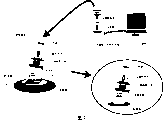
Fig. 2 represents the system diagram of temperature measuring and transmitter/receiver device of the present invention.
Fig. 3 represents the flow chart of embodiments of the present invention.
Fig. 4 represents the block diagram of embodiments of the present invention.
Fig. 5 represents in embodiments of the present invention, the figure of an example of the data of record.
Fig. 6 represents in embodiments of the present invention, the figure of an example of application.
Fig. 7 represents other the system diagram of embodiment of the present invention.
Fig. 8 represents other the block diagram of embodiment of the present invention.
Among the figure: 1~adhesive cushion; 2~reading device; 3~socket; 4~computer; 5~cable; 6~IC chip; 7~identification id code is rewritten platform; 8~cable.
The specific embodiment
Below, with reference to accompanying drawing, embodiments of the present invention are described.
Fig. 1 is, the reading device 2 of exploded view 2, and the block diagram of the details of built-in IC chip 6 in the adhesive cushion 1.
In reading device 2,10 for carrying out the control central processing unit (to call CPU in the following text) of reading device, 11 for and computer 4 carry out exchanges data external interface device (below, claim that exterior I/F), 12 is the console switch of reading device, 13 is the liquid crystal display part of reading device, 14 is the agitator that uses in CLK of system and the clock function, and 15 is the temporary transient memory of data that receives of preserving, and 16 for comprising the RF driver of resonant circuit, 17 is the RF receiving circuit, and 18 is antenna.
In addition, in adhesive cushion 1 in the built-in IC chip 6,20 is the CPU that controls, and 21 is RF portion, and 22 is antenna, 23 for the identification id code and, deposit the EEPROM of program, 24 are AD converter (to call A/D in the following text), 25 temperature sensors for the critesistor formation, 26 for rewriting the exterior I/F of the identification id code of storage in the EEPROM23, and 27 for having by will be with the generate electricity electricity-generating circuit of the electricity generate function that produces supply voltage of the electric wave rectification that antenna 22 receives.
Fig. 2 is, the system diagram of expression embodiments of the present invention, 1 is unfolded adhesive cushion on people's the skin, 2 for reading the data fetch device of data and preservation from the IC chip, 3 are computer and the socket that carries out the band charge function of data communication, 4 personal computers for responsible control whole system (below, claim computer), 5 cables for gang socket 3 and computer 4,6 is the IC chip that comprises in the adhesive cushion.
Fig. 1 is the block diagram of the details of expression embodiment, from socket 3, reading device 2 is taken out, near by the thermometric person,, export the faint wireless signal of 10mW degree from the antenna 18 of reading device 2 by opening operation switch 12, unfolded adhesive cushion 1 on people's the skin, receive this RF carrier wave, with the rectification of described RF carrier wave, and the self-excitation generating produces supply voltage.In adhesive cushion 1, be built-in with the IC chip 6 that can drive by described VDD, by the temperature sensor in the IC chip, measure by thermometric person's body temperature.
In addition, in an embodiment,, also can replace with internal battery though have the electricity-generating circuit that comes the self-excitation electricity by the electric wave that receives.
With measure by being combined of writing down among the EEPROM in thermometric person's temperature data and the described IC chip by thermometric person recognition data, by the RF portion in the described IC chip, from antenna, with described by thermometric person's recognition data and by the wireless output of thermometric person's temperature data.
In the described reading device that has the module that receives described wireless output, receive described wireless output, wireless data is converted to numerical data, in being converted to the temperature data of numerical data, the additional period data are recorded in the memorizer as the logging modle in the described reading device again.
Also can be with the identification of described temperature data, be certain temperature when above in its result, the warning of ringing arouses attention.
With temperature data and the time data that write down in the described memorizer, use the cable that is connected with socket, send in the computer, and be kept in the hard disk of equipment in the computer, finish a series of measurement, record, preservation work.
Below, the action of Fig. 2 flow chart according to Fig. 4 is described.
At first, near adhesive cushion 1 and open, the formant waveform that will produce in the RF of reading device 2 driver 16 passes through antenna 18, exports (step S1) with the faint wireless signal of 10mW degree with the console switch 12 of reading device 2.
On the other hand, receive the IC chip 6 of faint wireless signal, receive by antenna 22 and RF portion 21, and in electricity-generating circuit 27 carrier wave rectification and self-excitation generating are produced supply voltage VDD, the VDD that self-excitation is generated electricity supplies in IC chip 6 integral body (step S2).
CPU20 obtains described digital quantity, temporarily is kept in the depositor of CPU20, and CPU20, with temporary transient data of preserving in the described internal register, reach the ID code that has among the EEPROM that has in advance and combine, numerical data is exported to RF21 (step S4).
Then, reading device 2 in RF receiving circuit 17, receives the data from IC chip 6 by antenna 18, and RF receiving circuit 17 is converted to digital quantity with data, exports to CPU10 (step S6).
CPU10, on described digital quantity, additional current information of time is stored in (step S7) in the memorizer 15.
Finished to this to by thermometric person 1 people from the temperature survey to the record, judge whether all being finished by thermometric person's thermometric.
All when having been finished by thermometric person's temperature survey, the work that end temp is measured; When not finishing, return S1, carry out next by thermometric person's measurement, carry out repeatedly S1~S8 remaining by thermometric person's people for several times.
Fig. 4 is the block diagram of the details of the reading device of presentation graphs 2 and computer 4.10~18, to the circuit same with Fig. 3, attached same symbol, and omit its explanation.30 be can the operation system (below, title OS) CPU, 31 softwares, and from the hard disk (to call HDD in the following text) of the data of reading device 1 for preserve using, 32 is the exterior I/F of for example USB interface and so on that can be connected with internal bus, 33 is lcd controller, 34 is liquid crystal display part, and 35 is serial i/F, and 36 is the keyboard that is connected with serial i/F35,37 is serial i/F, and 38 is the mouse that is connected with serial i/F.
If to all being finished by thermometric person's measurement, data fetch device is inserted in the socket 3, in the data fetch device 2, by exterior I/F11 the data of storage in the memorizer 15 are sent, the data of described preservation are sent to computer 4 by cable 5, described computer 4 receives data by exterior I/F32, send in the hard disk 31, in hard disk 31, the data of record (by thermometric person's identification id data, temperature data, measurement date time data) are saved.
In addition, among the embodiment,, also can pass through radio communication, be sent in the computer 4 though showed by the example of the wire communication of cable.
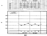
Fig. 5 is that the data that write down among the described HDD31, are preserved by the order of identification id data, temperature data, measurement date time data by the thermometric person each, and become a data base.
Also have, use application software, can use the data of preserving among the described data base with the CPU30 operation.
For example, Fig. 6 is, uses described data base's a example effectively, by being that unit figures with the record in everyone past with 1 day, 3 days, 1 week, can play effect in the grasp to patient's state, can use effectively the data of measuring.
Fig. 7 is, represents other the pie graph of embodiment of the present invention.In the embodiment of Fig. 7, be in Fig. 7, the identification id that the EEPROM23 in the adhesive cushion 1 that is built-in with the IC chip rewrites to be rewritten platform, and computer 4 is rewritten the cable 8 that platform 7 is connected with identification id with the difference of Fig. 1.To the circuit identical with Fig. 1, additional same symbol, and omit its explanation.
Computer 4 and identification id are rewritten platform 7, connect by cable 8, with computer 4, can the EEPROM23 in the IC chip easily be rewritten.
Identification id is rewritten in the platform 7, in order to rewrite the EEPROM23 in the adhesive cushion, is provided with splicing ear, uses described terminal, can rewrite the content of described EEPROM23.
Fig. 8 is that the reading device of Fig. 1 of presentation graphs 7 and computer 4 and identification id are rewritten the block diagram of the details of platform 7, to the circuit identical with Fig. 1, add prosign, and omit its explanation.
The place of interpolation is in adhesive cushion 1, has added the exterior I/F26 that can rewrite EEPROM23, and the place of interpolation is in computer 4, has added exterior I/F39, can carry out data communication with adhesive cushion 1.
Claims (6)
1. temperature measuring and transmitter/receiver device is characterized in that: comprising: temperature measuring and transmitting device and temperature measuring and receiving device,
Described temperature measuring and transmitting device has:
Receive the antenna of electric wave;
By coming the electricity-generating circuit of self-excitation electricity with the electric wave rectification that antenna receives;
Vary with temperature the pick off that resistance value changes;
The memorizer of storage cognizance code; And,
From described electricity-generating circuit supply line voltage, will be from the wireless output circuit of the wireless output of described cognizance code of storing in the temperature information of described temperature sensor and the described memorizer,
Described temperature measuring and receiving device has:
Supply with the electric wave supply circuit of electric wave to described temperature measuring and transmitting device;
Reception is from the receiving circuit of the described wireless output of described temperature measuring and transmitting device;
The central processing unit of additional period data in described temperature information that receives by described receiving circuit and described cognizance code;
Storage is by the storage part of described temperature information, described cognizance code and the described time data of described central processing unit acquisition; And,
Described temperature information, cognizance code and the described time data of storing in the described storage part sent to the external interface of personal computer.
2. temperature measuring and transmitter/receiver device according to claim 1 is characterized in that:
Having to be the A/D converter of digital signal from the analog signal conversion of described temperature sensor, and with digital signal with the wireless output of temperature information.
3. temperature measuring and transmitter/receiver device is characterized in that: comprising: temperature measuring and transmitting device and temperature measuring and receiving device,
Described temperature measuring and transmitting device has:
Battery as power supply;
The pick off that changes with the temperature inversion resistance value;
The memorizer of storage cognizance code; And,
From described battery supply line voltage, will be from the wireless output circuit of the wireless output of described cognizance code of storing in the temperature information of described temperature sensor and the described memorizer,
Described temperature measuring and receiving device has:
Reception is from the receiving circuit of the described wireless output of described temperature measuring and transmitting device;
The central processing unit of additional period data in described temperature information that receives by described receiving circuit and described cognizance code;
Storage is by the storage part of described temperature information, described cognizance code and the described time data of described central processing unit acquisition; And
Described temperature information, cognizance code and the described time data of storing in the described storage part sent to the external interface of personal computer.
4. temperature measuring and transmitter/receiver device according to claim 3 is characterized in that:
Having to be the A/D converter of digital signal from the analog signal conversion of described temperature sensor, and with digital signal with the wireless output of temperature information.
5. according to claim 1 or the described temperature measuring and transmitter/receiver device of claim 3, it is characterized in that: described temperature measuring and receiving device has can discern the described temperature information that receives, and is certain temperature when above in this result, the sound-producing device of sounding.
6. according to claim 1 or the described temperature measuring and transmitter/receiver device of claim 3, it is characterized in that: described memorizer can be rewritten.
Applications Claiming Priority (2)
| Application Number | Priority Date | Filing Date | Title |
|---|---|---|---|
| JP2003338859A JP2005106555A (en) | 2003-09-29 | 2003-09-29 | Temperature measurement transceiver |
| JP2003338859 | 2003-09-29 |
Publications (2)
| Publication Number | Publication Date |
|---|---|
| CN1602798A CN1602798A (en) | 2005-04-06 |
| CN100348148C true CN100348148C (en) | 2007-11-14 |
Family
ID=34534207
Family Applications (1)
| Application Number | Title | Priority Date | Filing Date |
|---|---|---|---|
| CNB2004100752599A Expired - Fee Related CN100348148C (en) | 2003-09-29 | 2004-09-13 | Temperature measuring and transmitter/receiver device |
Country Status (4)
| Country | Link |
|---|---|
| JP (1) | JP2005106555A (en) |
| KR (1) | KR20050031433A (en) |
| CN (1) | CN100348148C (en) |
| TW (1) | TWI278303B (en) |
Cited By (2)
| Publication number | Priority date | Publication date | Assignee | Title |
|---|---|---|---|---|
| CN102175341A (en) * | 2010-11-11 | 2011-09-07 | 浙江图维电力科技有限公司 | Accurate temperature measurement technology and device thereof for cable connector based on radio frequency technology |
| TWI568413B (en) * | 2015-10-21 | 2017-02-01 | 國立交通大學 | Bio-signal sensor |
Families Citing this family (11)
| Publication number | Priority date | Publication date | Assignee | Title |
|---|---|---|---|---|
| US20070118030A1 (en) * | 2005-11-22 | 2007-05-24 | Isense Corporation | Method and apparatus for analyte data telemetry |
| US9151679B2 (en) * | 2008-06-30 | 2015-10-06 | Intel Corporation | Temperature measurement in electronic devices |
| JP5697233B2 (en) * | 2010-09-16 | 2015-04-08 | 東日本旅客鉄道株式会社 | Environmental information measuring apparatus, environmental information measuring system, and environmental information measuring method |
| CN101986116B (en) * | 2010-10-23 | 2015-10-21 | 洛阳轴研科技股份有限公司 | Inner ring measuring method of temperature during bearing inner race High Rotation Speed |
| CN104000559A (en) * | 2013-02-25 | 2014-08-27 | 詹宗纮 | Body temperature monitoring system |
| GB2517907B (en) * | 2013-08-09 | 2018-04-11 | Drayson Tech Europe Ltd | RF Energy Harvester |
| MX361654B (en) * | 2014-09-22 | 2018-12-13 | Helen Of Troy Ltd | Thermometer with wireless functionality. |
| CN105509904A (en) * | 2014-09-24 | 2016-04-20 | 福建新大陆电脑股份有限公司 | Temperature acquisition apparatus based on wireless communication |
| WO2016073408A1 (en) * | 2014-11-07 | 2016-05-12 | 3M Innovative Properties Company | Wireless sensing system using sensing device with excitation element |
| CN108303187A (en) * | 2018-02-08 | 2018-07-20 | 西安兴硕电子科技有限公司 | A kind of rotary body temp measuring system of wireless signal transmission |
| CN113865738A (en) * | 2021-09-27 | 2021-12-31 | 重庆京东方电子科技有限公司 | Temperature measuring device, temperature detecting method, client and medium |
Citations (6)
| Publication number | Priority date | Publication date | Assignee | Title |
|---|---|---|---|---|
| JPH09126905A (en) * | 1995-11-07 | 1997-05-16 | Nec Corp | Body temperature pick-up |
| CN2339982Y (en) * | 1998-07-09 | 1999-09-22 | 周欣 | Electronic thermometer |
| CN2446955Y (en) * | 2000-10-30 | 2001-09-12 | 捷威科技股份有限公司 | Wireless body temperature monitoring device |
| CN2461482Y (en) * | 1999-12-21 | 2001-11-28 | 黄昭荣 | Human body temp warner |
| JP2003069666A (en) * | 2001-08-27 | 2003-03-07 | Yamaha Corp | Mobile telephone equipment |
| WO2003078948A1 (en) * | 2002-03-20 | 2003-09-25 | Sakano, Kazuhito | Temperature measuring device and temperature measuring method |
Family Cites Families (6)
| Publication number | Priority date | Publication date | Assignee | Title |
|---|---|---|---|---|
| JPH0370856U (en) * | 1989-11-14 | 1991-07-17 | ||
| JP3174120B2 (en) * | 1992-01-22 | 2001-06-11 | テルモ株式会社 | Electronic thermometer |
| JPH0989676A (en) * | 1995-09-21 | 1997-04-04 | Casio Comput Co Ltd | Electronic clinical thermometer |
| JP2000074745A (en) * | 1998-08-27 | 2000-03-14 | Panetto:Kk | Abnormal bodily temperature detecting sensor and its report system |
| JP2001314378A (en) * | 2000-05-11 | 2001-11-13 | Yokohama Rubber Co Ltd:The | Thermomonitor system |
| JP2003130732A (en) * | 2001-10-22 | 2003-05-08 | A & D Co Ltd | Electronic clinical thermometer |
-
2003
- 2003-09-29 JP JP2003338859A patent/JP2005106555A/en active Pending
-
2004
- 2004-09-13 CN CNB2004100752599A patent/CN100348148C/en not_active Expired - Fee Related
- 2004-09-24 KR KR1020040077193A patent/KR20050031433A/en not_active Application Discontinuation
- 2004-09-27 TW TW093129320A patent/TWI278303B/en not_active IP Right Cessation
Patent Citations (6)
| Publication number | Priority date | Publication date | Assignee | Title |
|---|---|---|---|---|
| JPH09126905A (en) * | 1995-11-07 | 1997-05-16 | Nec Corp | Body temperature pick-up |
| CN2339982Y (en) * | 1998-07-09 | 1999-09-22 | 周欣 | Electronic thermometer |
| CN2461482Y (en) * | 1999-12-21 | 2001-11-28 | 黄昭荣 | Human body temp warner |
| CN2446955Y (en) * | 2000-10-30 | 2001-09-12 | 捷威科技股份有限公司 | Wireless body temperature monitoring device |
| JP2003069666A (en) * | 2001-08-27 | 2003-03-07 | Yamaha Corp | Mobile telephone equipment |
| WO2003078948A1 (en) * | 2002-03-20 | 2003-09-25 | Sakano, Kazuhito | Temperature measuring device and temperature measuring method |
Cited By (3)
| Publication number | Priority date | Publication date | Assignee | Title |
|---|---|---|---|---|
| CN102175341A (en) * | 2010-11-11 | 2011-09-07 | 浙江图维电力科技有限公司 | Accurate temperature measurement technology and device thereof for cable connector based on radio frequency technology |
| CN102175341B (en) * | 2010-11-11 | 2013-11-13 | 浙江图维电力科技有限公司 | Accurate temperature measurement technology and device thereof for cable connector based on radio frequency technology |
| TWI568413B (en) * | 2015-10-21 | 2017-02-01 | 國立交通大學 | Bio-signal sensor |
Also Published As
| Publication number | Publication date |
|---|---|
| TW200511974A (en) | 2005-04-01 |
| CN1602798A (en) | 2005-04-06 |
| JP2005106555A (en) | 2005-04-21 |
| KR20050031433A (en) | 2005-04-06 |
| TWI278303B (en) | 2007-04-11 |
Similar Documents
| Publication | Publication Date | Title |
|---|---|---|
| CN100348148C (en) | Temperature measuring and transmitter/receiver device | |
| CN104350365B (en) | temperature measurement system and method | |
| Zhao et al. | NFC-WISP: A sensing and computationally enhanced near-field RFID platform | |
| US20050226310A1 (en) | Adhesive clinical thermometer pad and temperature measuring pad | |
| EP0417274B1 (en) | Electronic clinical thermometer | |
| US20070051369A1 (en) | Apparatus, method, and medium calculating calorie consumption | |
| CN107361755A (en) | Intelligent watch with dysarteriotony prompting | |
| CN106913316A (en) | Internal temperature determines device, wrist installing type device and internal temperature assay method | |
| CN101976309A (en) | Electronic medical record input device | |
| Magno et al. | Autonomous smartwatch with flexible sensors for accurate and continuous mapping of skin temperature | |
| CN1299638C (en) | Temperature measuring and receiving device | |
| CN1602799A (en) | Temperature measuring and transmitting device | |
| TW201021759A (en) | Integrated system for transmitting medical measurements through infrared rays | |
| US20070226416A1 (en) | Portable random access memory | |
| CN202859085U (en) | Biomedicine device with close range wireless transmission function | |
| JP2006340952A (en) | Bioinformation management system and program therefor | |
| CN101297751B (en) | System and method for measuring and displaying health information | |
| CN110167435B (en) | User terminal device and data transmission method | |
| JPS63133030A (en) | Electronic thermometer | |
| US20050147151A1 (en) | System and method for measuring temperature | |
| CN213274602U (en) | Passive NFC temperature sensor | |
| US20050163189A1 (en) | Temperature information reader | |
| CN108451512A (en) | A kind of wearable medical monitoring equipment based on Android phone | |
| CN108024168A (en) | Biological information senses wired earphone | |
| CN205594624U (en) | Novel be used for temperature taking integrated circuit |
Legal Events
| Date | Code | Title | Description |
|---|---|---|---|
| C06 | Publication | ||
| PB01 | Publication | ||
| C10 | Entry into substantive examination | ||
| SE01 | Entry into force of request for substantive examination | ||
| C14 | Grant of patent or utility model | ||
| GR01 | Patent grant | ||
| C17 | Cessation of patent right | ||
| CF01 | Termination of patent right due to non-payment of annual fee |
Granted publication date: 20071114 Termination date: 20120913 |