CN100340398C - Gap adjuster for laminating rolls - Google Patents
Gap adjuster for laminating rolls Download PDFInfo
- Publication number
- CN100340398C CN100340398C CNB038122081A CN03812208A CN100340398C CN 100340398 C CN100340398 C CN 100340398C CN B038122081 A CNB038122081 A CN B038122081A CN 03812208 A CN03812208 A CN 03812208A CN 100340398 C CN100340398 C CN 100340398C
- Authority
- CN
- China
- Prior art keywords
- spacer block
- block body
- body element
- width
- roller
- Prior art date
- Legal status (The legal status is an assumption and is not a legal conclusion. Google has not performed a legal analysis and makes no representation as to the accuracy of the status listed.)
- Expired - Fee Related
Links
Images


Classifications
-
- B—PERFORMING OPERATIONS; TRANSPORTING
- B32—LAYERED PRODUCTS
- B32B—LAYERED PRODUCTS, i.e. PRODUCTS BUILT-UP OF STRATA OF FLAT OR NON-FLAT, e.g. CELLULAR OR HONEYCOMB, FORM
- B32B43/00—Operations specially adapted for layered products and not otherwise provided for, e.g. repairing; Apparatus therefor
-
- B—PERFORMING OPERATIONS; TRANSPORTING
- B32—LAYERED PRODUCTS
- B32B—LAYERED PRODUCTS, i.e. PRODUCTS BUILT-UP OF STRATA OF FLAT OR NON-FLAT, e.g. CELLULAR OR HONEYCOMB, FORM
- B32B37/00—Methods or apparatus for laminating, e.g. by curing or by ultrasonic bonding
- B32B37/0046—Methods or apparatus for laminating, e.g. by curing or by ultrasonic bonding characterised by constructional aspects of the apparatus
- B32B37/0053—Constructional details of laminating machines comprising rollers; Constructional features of the rollers
-
- Y—GENERAL TAGGING OF NEW TECHNOLOGICAL DEVELOPMENTS; GENERAL TAGGING OF CROSS-SECTIONAL TECHNOLOGIES SPANNING OVER SEVERAL SECTIONS OF THE IPC; TECHNICAL SUBJECTS COVERED BY FORMER USPC CROSS-REFERENCE ART COLLECTIONS [XRACs] AND DIGESTS
- Y10—TECHNICAL SUBJECTS COVERED BY FORMER USPC
- Y10T—TECHNICAL SUBJECTS COVERED BY FORMER US CLASSIFICATION
- Y10T156/00—Adhesive bonding and miscellaneous chemical manufacture
- Y10T156/17—Surface bonding means and/or assemblymeans with work feeding or handling means
- Y10T156/1702—For plural parts or plural areas of single part
- Y10T156/1712—Indefinite or running length work
- Y10T156/1741—Progressive continuous bonding press [e.g., roll couples]
Abstract
An apparatus and method for lamination are provided, which are advantageously used in intermittent lamination and fixed-gap lamination, the apparatus comprising first and second laminating rollers defining a laminating gap therebetween and at least one gapping block positioned between the first and second rollers such that the gapping block determines and maintains a minimum gap width. The gapping block comprises a rigid gapping block body, which may be adjustable in width, and four or more load wheels rotatably attached to the gapping block body which ride on a portion of the first and second rollers.
Description
Technical field
The present invention relates to laminating method and be included in first and second laminating rolls that form a lamination gap therebetween and be arranged between first and second laminating rolls to determine and to keep the equipment of at least one spacer block of minimum gap width.Spacer block comprises the spacer block main body of the rigidity that can be adjusted and is rotatably attached to four or more a plurality of load wheels of spacer block main body on width, and described spacer block straddles on the part of first and second rollers.
Background technology
United States Patent (USP) the 6th, 347 has disclosed a kind of lash adjusting device that is used to comprise by the rotary press of separated two rollers of adjustable eccentric part No. 585.
United States Patent (USP) the 5th, 456 has disclosed a kind of system that is used to adjust the wheel load gap No. 871, and its adopts load measurement unit and active feedback, and usually by a microprocessor between the centre.
U.S. Patent Application Publication No. US2002/00144509 A1 has disclosed a kind of roll seam adjusting device, it has a minimum clearance setting device, this device comprises the retainer of pair of opposing, a moving assembly that is attached to supporting one roller, and another then is attached to device framework.
Summary of the invention
In brief, the invention provides a kind of equipment, this equipment is included in first and second rollers that form a gap therebetween and is arranged between first and second rollers to determine and to keep at least one spacer block of a minimum gap width.Spacer block comprises a rigidity spacer block main body and is rotatably attached to four or more a plurality of load wheels of spacer block main body, and described spacer block is arranged between first and second rollers, so that at least two load wheels contact each roller.In another embodiment, the width of spacer block is adjustable.
In another aspect, the invention provides that a kind of first roller by entering a lamination equipment and the gap between second roller are with the coarctate method of all lamellas simultaneously by making two-layer or composite wafer material, described equipment also comprises and being arranged between first and second rollers to determine and to keep at least one spacer block of a minimum gap width.
In another aspect, the invention provides that a kind of first roller by entering a lamination equipment and the gap between second roller are with the coarctate method of all lamellas simultaneously by making two-layer or composite wafer material, described equipment also comprises and being arranged between first and second rollers to determine and to remain at least one spacer block of the constant constant clearance width of maintenance in the whole lamination process.
In another aspect, the invention provides a kind of adjustable spacer block, described spacer block comprises: the one first spacer block body element that is attached with two or more load wheels rotationally; Be attached with one second spacer block body element of two or more load wheels rotationally, and, this second spacer block body element and the described first spacer block body element be assembled into make two parts can along the direction of spacer block body width relative to each other straight line move, and, when assembling in this wise, at least one surface of arbitrary spacer block body element one side of another spacer block body element relatively tilts to the surface; Be arranged on the voussoir between the opposed face; And thereby an adjustment screw of spacer block body width is determined in the position of definite voussoir between opposed face.
In this application, " lamination " refers to two-layer or composite wafer material combined.
An advantage of the invention is provides a kind of laminating method, this method can prevent from the process that discontinuous thin slice is laminated to discontinuously continuous coiled material continuous coiled material to be caused damage.
The accompanying drawing summary
Fig. 1 illustrates the stereogram of gapping block according to the present invention;
Fig. 2 is the left view of spacer block shown in Figure 1;
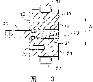
Fig. 3 is along Fig. 2 center line 3-3 sectional view;
Fig. 4 is the vertical cross-section diagram of spacer block shown in Figure 1;
Fig. 5 is the cutaway view that axis intercepted of an equipment according to the present invention along two rollers that pass equipment.
The specific embodiment
Referring to Fig. 1-4, spacer block according to the present invention comprises a spacer block main body, and this spacer block main body comprises one first spacer block body element 10 and one second spacer block body element 20.Two load wheels 31,32 are rotatably attached to the first spacer block body element 10.Two load wheels 33,34 are rotatably attached to the second spacer block body element 20.Additional load wheels can be installed on arbitrary spacer block body element.Perhaps, in the place that does not need the spacer block body width is adjusted, the spacer block main body can be the part of a single main body of four of installations or more a plurality of load wheels.Arrow A indicates the size of representing the spacer block body width.When using with a pair of roller, the spacer block body width is the straight-line dimension along the measured spacer block main body that gets of direction that is parallel to the gap width measurement between first and second rollers.In use, must stop the spacer block body element on direction, to be moved perpendicular to the spacer block body width.The first spacer block body element 10 can comprise arm 15, and they stop the second spacer block body element 20 to be moved on the one or more directions perpendicular to the spacer block width.In addition, the one or more lateral constraints (shown in Figure 5, as will to discuss hereinafter) that are attached to the part of device framework or forming device framework can stop the second spacer block body element, the 20 relative first spacer block body element 10 to be moved on the one or more directions perpendicular to the spacer block body width.After having adjusted the spacer block body width, the first and second spacer block body element, 10,20 bolts can be connected to one or more lateral constraints by screwed hole 12,22.
The first spacer block body element 10 and the second spacer block body element 20 comprise the surface of facing 11 and 21 respectively.In the opposed face 11 and 21 one or both tilt.By interacting, can use voussoir 40 to adjust the spacer block body width with surface 11 and 21.Use and adjust the position that screw 41 changes voussoir 40, thereby change the spacer block body width.In one embodiment, the thread spindle of adjustment screw 41 engages the screwed hole in the lateral constraints, and described lateral constraints then is attached to the part (shown in Figure 5, as will to discuss hereinafter) of device framework or forming device framework.Usually, by screwed hole 12 the first spacer block body element, 10 bolts are connected to one or more lateral constraints, adjust the spacer block body width by means of adjusting screw 41, then, the second spacer block body element, 20 bolts are connected to one or more lateral constraints by screwed hole 22.
Referring to Fig. 5, that an equipment according to the present invention comprises is aforesaid, comprise the first spacer block body element 10, the second spacer block body element 20, load wheels 32,34, voussoir 40 and all spacer blocks of adjusting screw 41.Lateral constraints 50 prevents that the second spacer block body element, the 20 relative first spacer block body element 10 are moved along the direction perpendicular to the spacer block body width.Lateral constraints 50 is attached to device framework by unshowned syndeton.The first spacer block body element 10 can be connected to lateral constraints 50 by through hole 51 and screwed hole 12 bolts.The thread spindle of adjustment screw 41 engages the screwed hole 53 in the lateral constraints 50.Adjust the spacer block body width by means of adjusting screw 41 being used on voussoir 40.Can the second spacer block body element, 20 bolts be connected to lateral constraints 50 by through hole 52 and screwed hole 22 then.
This equipment also comprises one first roller 60, and this first roller 60 comprises having a radius r
P1A pressurised zone and have a radius r
G1Two spacer block zones 62,63.As shown in the figure, first roller also additionally comprises the 72 interactional shaft portions 64,65 with bearing surface mechanism.Second roller 80 comprises having a radius r
P2A pressurised zone 81 and have a radius r
G2Two spacer block zones 82,83.Usually, r
P1Equal r
P2And r
G1Equal r
G2As shown in the figure, first roller also comprises the 92 interactional shaft portions 84,85 with bearing surface mechanism.Between discontiguous first roller 60 and second roller 80, form a narrow lamination gap.The lamination gap of embodiment shown in Fig. 5 is too narrow, so that can not be clearly shown that.Can be by any or both that drive such as motor or similar device in first roller 60 and second roller 80.Normally drive both.Usually, first roller 60 is in transmission connection with second roller 80 and is in the same place, so that they have identical speed at gap location.In one embodiment, by driving first roller 60 and second roller 80 with belt pulley 68 and 88 interactional leather belt driving mechanisms.
Bearing comprises bear box 71,91 and bearing surface mechanism 72,92, and they belong to the known type such as ball bearing, roller bearing, needle bearing and similar bearing.Bear box 71,91 is attached to device framework 100, so that can apply on bear box 71,91 or keep-up pressure, and this is used for making first and second rollers 60,80 to be close together.Bear box can be fixed on the framework 100, and is perhaps attached by means of pneumatic or hydraulic piston 101 and cylinder 103, as shown in the figure.Bearning mechanism can be formed for the part of the driving mechanism of arbitrary or two rollers.
In laminating method according to the present invention, by making two or multi-disc sheeting, and press them together simultaneously by entering the narrow gap between first roller 60 and second roller 80.Usually, drive the one or both in first roller 60 and second roller 80, more generally be to drive both.Can apply heat, solvent or binding agent to a layer or a plurality of layer, to help combination.First roller 60 and second roller 80 can heat by any suitable method, but normally heat internally by the method such as electrical heating or recirculated hot air, water or oil.
Use apparatus and method according to the invention with help requirement carry out the discontinuous lamination that is the lamination of being wanted one or more layers in lamination process be appear at discontinuously in the lamination gap occasion.In this case, product can be a continuous coiled material that has additional sheet materials sheet discontinuous, laminated thereon.Under the situation of discontinuous lamination,, then may crush or damage continuous coiled material if when discontinuous sheeting does not appear in the gap, still apply whole lamination pressures.A minimum gap width method and apparatus according to the invention can be kept by using, this damage can be prevented for continuous coiled material.In addition,, may be in lamination process the leading edge of the laminate that is interrupted be rounded, can avoid such situation to take place by using according to equipment of the present invention if when discontinuous sheeting does not appear in the gap, apply whole lamination pressures.
Equipment according to the present invention also has other advantage, does not consider the bearing clearance the roller bearing from determining the gap width aspect, thereby has not also considered the variation of bearing clearance again.The variation of bearing clearance especially becomes problem when laminating roll is heated, be suitable for and can set more accurate and very big gap width according to equipment of the present invention.In addition, equipment according to the present invention can be used for fixed-gap lamination, and in such laminating operation, gap width is constant basically in whole lamination process.In order to realize fixed-gap lamination, must pair of rollers apply enough power, wanted any resistance that material was produced of lamination to overcome.
Use apparatus and method according to the invention help with catalyst decal be laminated on the polyelectrolyte film, particularly such as Nafion
TMOr Flemion
TMAnd so on the operation on the change fluoro-containing copolymer film of sulphur.Catalyst decal is usually included in the catalyst dispersion of the skim on the back sheet.After being laminated to catalyst dispersion on the polyelectrolyte film, remove the decal paper back sheet.Use apparatus and method according to the invention to help the meticulous or very thin film of castable, usually thickness be 100 microns or thinner, more generally thickness be 50 microns or thinner and more usually thickness be 30 millimeters or thinner.
Concerning those those skilled in the art that, various modification of the present invention and alternative will become apparent, and can not exceed protection scope of the present invention and principle.And, also should be understood that, the illustrative embodiment that is proposed above the present invention should not being confined to inadequately.
Claims (10)
1. equipment that comprises first and second rollers, described first and second rollers are parallel, and form a gap between described first and second rollers, and this gap has a gap width;
Described equipment also comprises at least one spacer block, and described spacer block comprises a rigidity spacer block main body and is rotatably attached to four or more a plurality of load wheels of described spacer block main body;
Wherein, described spacer block is arranged between described first and second rollers, so that at least two load wheels contact each roller, this spacer block determines and keep the gap width of a minimum by this.
2. equipment as claimed in claim 1 is characterized in that, each described roller comprises at least one pressurised zone and at least one spacer block zone, and described roller has a radius r in described pressurised zone
p, described roller has a radius r in described spacer block zone
g, and the described load wheels of described spacer block contacts described roller in described spacer block location, and, r
pBe not equal to r
g
3. equipment as claimed in claim 1 or 2, it is characterized in that, described spacer block main body has a spacer block body width, this width is the straight-line dimension along the measured spacer block main body that gets of direction that is parallel to the gap width measurement between first and second rollers, and described spacer block main body comprises the device of adjusting described spacer block body width.
4. equipment as claimed in claim 3 is characterized in that, described spacer block main body comprises:
One first spacer block body element, two or more load wheels are rotatably attached to the described first spacer block body element;
One second spacer block body element, two or more load wheels are rotatably attached to the described second spacer block body element, and, described second spacer block body element and the described first spacer block body element be assembled into make two parts can along the direction of spacer block body width relative to each other straight line move, and, when assembling in this wise, at least one surface of arbitrary spacer block body element one side of another spacer block body element relatively tilts to the surface;
Be arranged on the voussoir between described inclined surface and the described opposed face; And
Thereby determine an adjustment screw of the definite spacer block body width in the position of described voussoir between described inclined surface and described opposed face.
5. one kind by making two-layer or composite wafer material one first roller by entering a lamination equipment and the gap between one second roller method of coming the described material of lamination simultaneously, described first and second rollers are parallel, and form a gap between described first and second rollers, this gap has a gap width;
Wherein, one spacer block is arranged between described first and second rollers, described spacer block comprises a rigidity spacer block main body and is rotatably attached to four or more a plurality of load wheels of described spacer block main body, and described spacer block is arranged to make at least two load wheels to contact each roller, and this spacer block determines and keep the gap width of a minimum by this.
6. method as claimed in claim 5 is characterized in that, two spacer blocks are set between described first and second rollers, so that at least two load wheels of each spacer block contact each roller, spacer block determines and keep the gap width of a minimum by this; And, the gap length that two spacer blocks separated from one another are given.
7. as claim 5 or 6 described methods, it is characterized in that each described roller comprises at least one pressurised zone and at least one spacer block zone, described roller has a radius r in described pressurised zone
p, described roller has a radius r in described spacer block zone
g, and the described load wheels of described spacer block contacts described roller in described spacer block location, and, r
pGreater than r
g
8. method as claimed in claim 7, it is characterized in that, described spacer block main body has a spacer block body width, this width is the straight-line dimension along the measured spacer block main body that gets of direction that is parallel to the gap width measurement between first and second rollers, and described spacer block main body comprises the device of adjusting described spacer block body width.
9. method as claimed in claim 8 is characterized in that, described spacer block main body comprises:
One first spacer block body element, two or more load wheels are rotatably attached to the described first spacer block body element;
One second spacer block body element, two or more load wheels are rotatably attached to the described second spacer block body element, and, described second spacer block body element and the described first spacer block body element be assembled into make two parts can along the direction of spacer block body width relative to each other straight line move, and, when assembling in this wise, at least one surface of arbitrary spacer block body element one side of another spacer block body element relatively tilts to the surface;
Be arranged on the voussoir between described inclined surface and the described opposed face; And
Thereby determine an adjustment screw of the definite spacer block body width in the position of described voussoir between described inclined surface and described opposed face.
10. spacer block, this spacer block comprises:
One first spacer block body element, two or more load wheels are rotatably attached to the described first spacer block body element;
One second spacer block body element, two or more load wheels are rotatably attached to the described second spacer block body element, and, described second spacer block body element and the described first spacer block body element be assembled into make two parts can along the direction of spacer block body width relative to each other straight line move, and, when assembling in this wise, at least one surface of arbitrary spacer block body element one side of another spacer block body element relatively tilts to the surface;
Be arranged on the voussoir between described inclined surface and the described opposed face; And
Thereby determine an adjustment screw of the definite spacer block body width in the position of described voussoir between described inclined surface and described opposed face.
Applications Claiming Priority (2)
| Application Number | Priority Date | Filing Date | Title |
|---|---|---|---|
| US10/115,777 US6780276B2 (en) | 2002-04-03 | 2002-04-03 | Gap adjuster for laminating rolls |
| US10/115,777 | 2002-04-03 |
Publications (2)
| Publication Number | Publication Date |
|---|---|
| CN1655931A CN1655931A (en) | 2005-08-17 |
| CN100340398C true CN100340398C (en) | 2007-10-03 |
Family
ID=28673837
Family Applications (1)
| Application Number | Title | Priority Date | Filing Date |
|---|---|---|---|
| CNB038122081A Expired - Fee Related CN100340398C (en) | 2002-04-03 | 2003-02-11 | Gap adjuster for laminating rolls |
Country Status (10)
| Country | Link |
|---|---|
| US (1) | US6780276B2 (en) |
| EP (1) | EP1490223B1 (en) |
| JP (1) | JP4327608B2 (en) |
| KR (1) | KR20040105828A (en) |
| CN (1) | CN100340398C (en) |
| AT (1) | ATE359910T1 (en) |
| AU (1) | AU2003213034A1 (en) |
| CA (1) | CA2481031A1 (en) |
| DE (1) | DE60313308T2 (en) |
| WO (1) | WO2003084749A1 (en) |
Families Citing this family (15)
| Publication number | Priority date | Publication date | Assignee | Title |
|---|---|---|---|---|
| US6868890B2 (en) * | 2002-04-03 | 2005-03-22 | 3M Innovative Properties Company | Method and apparatus for peeling a thin film from a liner |
| US6740131B2 (en) | 2002-04-03 | 2004-05-25 | 3M Innovative Properties Company | Apparatus for automatically fabricating fuel cell |
| US7432009B2 (en) | 2002-04-03 | 2008-10-07 | 3M Innovative Properties Company | Lamination apparatus and methods |
| US20030188615A1 (en) * | 2002-04-03 | 2003-10-09 | 3M Innovative Properties Company | Angled product transfer conveyor |
| US20030190226A1 (en) * | 2002-04-03 | 2003-10-09 | 3M Innovative Properties Company | Apparatus and method for singulating porous fuel cell layers using adhesive tape pick head |
| US7195690B2 (en) | 2003-05-28 | 2007-03-27 | 3M Innovative Properties Company | Roll-good fuel cell fabrication processes, equipment, and articles produced from same |
| KR101036641B1 (en) | 2004-07-09 | 2011-05-24 | 주식회사 포스코 | An apparatus for manufacturing compacted irons of reduced materials comprising fine direct reduced irons and an apparatus for manufacturing molten irons using the same |
| US7641801B2 (en) * | 2007-02-28 | 2010-01-05 | Vale Inco Limited | Method for removing manganese from nickel laterite waste liquors |
| KR101235714B1 (en) * | 2011-07-25 | 2013-02-21 | 아이디피 (주) | Positioning controller for laminating film of laminater |
| FR3001180B1 (en) * | 2013-01-18 | 2015-07-10 | Batscap Sa | ROLLING DEVICE, ROLLING METHOD, ELECTROLYTE FILM THUS OBTAINED, AND ENERGY STORAGE ASSEMBLY FORMED FROM AT LEAST ONE LAMINATED FILM |
| CN103213370B (en) * | 2013-04-23 | 2015-02-18 | 任济森 | Novel pinch roller device |
| GB201508394D0 (en) * | 2015-05-15 | 2015-07-01 | Vivid Laminating Technologies Ltd | Pneumatic positioning of laminator rollers |
| CN107009629B (en) * | 2017-04-18 | 2019-07-26 | 苏州赛腾精密电子股份有限公司 | A kind of rolling mechanism and abutted equipment |
| CN108724898B (en) * | 2018-05-18 | 2020-04-03 | 盐城东科机械科技有限公司 | Firm type laminating machine laminating mechanism |
| IT202000018634A1 (en) * | 2020-07-30 | 2022-01-30 | Arca Tech S R L | STORAGE AND DISPENSING MODULE |
Citations (2)
| Publication number | Priority date | Publication date | Assignee | Title |
|---|---|---|---|---|
| US4676862A (en) * | 1984-06-01 | 1987-06-30 | Hoechst Aktiengesellschaft | Laminating station |
| CN1134687A (en) * | 1993-09-10 | 1996-10-30 | 戴维·P·古德里奇 | Method and apparatus for producing individual rolls of packing material |
Family Cites Families (65)
| Publication number | Priority date | Publication date | Assignee | Title |
|---|---|---|---|---|
| US2710234A (en) * | 1950-05-22 | 1955-06-07 | Hughes Aircraft Co | Fluid-bearing mount |
| US3178041A (en) | 1961-10-23 | 1965-04-13 | Libbey Owens Ford Glass Co | Sheet handling apparatus |
| US3285112A (en) | 1964-08-03 | 1966-11-15 | Lamb Grays Harbor Co Inc | Vacuum controlling of sheet delivery |
| IL23954A (en) | 1964-08-04 | 1969-06-25 | Ibm | Apparatus for guiding and feeding a continuous web |
| US3380788A (en) * | 1964-12-28 | 1968-04-30 | Gen Electric | Hydrostatic bearing |
| US3359046A (en) * | 1965-10-22 | 1967-12-19 | Hugh L Dryden | Bismuth-lead coatings for gas bearings used in atmospheric environments and vacuum chambers |
| US3477558A (en) * | 1966-10-27 | 1969-11-11 | Fred J Fleischauer | Air lift and vacuum conveyors and foraminous belt means therefor |
| DE1928110A1 (en) | 1969-06-03 | 1970-12-10 | Viktor Prochaska | Device for loading, conveying, sorting and stacking of materials such as Sheets, veneers, plastics, cardboard and plates of all kinds |
| AT314323B (en) | 1970-10-09 | 1974-03-25 | Malew Eng Ltd | Pressing or punching tool or the like. and method of making it |
| US3861259A (en) | 1973-06-04 | 1975-01-21 | Harris Intertype Corp | Sheet delivery system |
| US3946920A (en) | 1974-02-22 | 1976-03-30 | Xerox Corporation | Vacuum system control |
| US4168772A (en) | 1974-10-01 | 1979-09-25 | General Battery Corporation | Apparatus and method for stacking battery plates and separators |
| DE2610628C3 (en) | 1976-03-13 | 1979-09-27 | Dornier Gmbh, 7990 Friedrichshafen | Device for cutting out plate-shaped core materials for sandwich components |
| US4143871A (en) | 1976-07-01 | 1979-03-13 | Levi Strauss & Company | Facing ply separator |
| DE2900663C2 (en) * | 1979-01-10 | 1982-12-16 | FAG Kugelfischer Georg Schäfer & Co, 8720 Schweinfurt | Process for the manufacture and testing of rolling elements |
| JPS5598040A (en) | 1979-01-23 | 1980-07-25 | Toppan Printing Co Ltd | Paper feeder by adhesive tape |
| FR2456613A1 (en) | 1979-05-16 | 1980-12-12 | Reine Yvan | Cutting slots in flexible PVC film - to control folding axes, to isolate and prepare packaging film in one operation |
| US4236814A (en) | 1979-06-13 | 1980-12-02 | A. B. Dick Company | Transport system for advancing copy sheets through tandem duplicating system |
| JPS5793854A (en) | 1980-11-29 | 1982-06-11 | Matsushita Electric Works Ltd | Single-plate piling method and apparatus therefor |
| US4381596A (en) | 1981-02-04 | 1983-05-03 | Mac Engineering & Equip. Co., Inc. | Method and apparatus for battery plate stacking |
| IT1138810B (en) | 1981-06-23 | 1986-09-17 | Rockwell Rimoldi Spa | PICKER OF PIECES STACKED WITH SOCKETS PROVIDED WITH ADHESIVE TAPE |
| US4360260A (en) | 1981-10-05 | 1982-11-23 | Polaroid Corporation | Spreader roller system having adjustable roller gap |
| US4534549A (en) | 1982-06-22 | 1985-08-13 | General Battery Corporation | Automatic battery stacker |
| US4784380A (en) | 1982-06-22 | 1988-11-15 | General Battery Corporation | Automatic battery stacker |
| US4728093A (en) | 1982-06-22 | 1988-03-01 | General Battery Corporation | Automatic battery stacker |
| DE3336426A1 (en) | 1983-10-06 | 1985-04-18 | Maschinenfabrik Herbert Meyer KG, 8000 München | DEVICE FOR RECORDING LARGE WORKPIECES |
| DE3343811A1 (en) | 1983-12-03 | 1985-06-13 | Babcock-BSH AG vormals Büttner-Schilde-Haas AG, 4150 Krefeld | Suction belt conveyor |
| JPS62244830A (en) | 1986-04-14 | 1987-10-26 | Yoshiyuki Kobayashi | Method and device for transferring cloth and the like |
| US5048182A (en) | 1988-02-22 | 1991-09-17 | Robbins Edward S Iii | Methods for fabricating pattern rolls |
| US4819928A (en) * | 1987-09-21 | 1989-04-11 | Mobil Oil Corporation | Plastic film air table conveyor |
| IT1213837B (en) | 1987-10-14 | 1990-01-05 | Solis Srl | TEMPORARY TAKING DEVICE OF KNITTED TEXTILE ITEMS, ESPECIALLY TUBULAR |
| EP0313088B1 (en) * | 1987-10-23 | 1995-01-04 | Fujitsu Limited | A suction-type sheet-carrying mechanism for an image-forming apparatus |
| GB8822328D0 (en) * | 1988-09-22 | 1988-10-26 | Stoddard Sekers Int | Pressure roller assembly |
| JPH03128851A (en) | 1989-10-13 | 1991-05-31 | Minolta Camera Co Ltd | Image formation apparatus |
| JP2676947B2 (en) | 1989-10-13 | 1997-11-17 | ミノルタ株式会社 | Image forming device |
| US5063415A (en) * | 1989-10-13 | 1991-11-05 | Minolta Camera Kabushiki Kaisha | Image forming apparatus |
| DE4013302A1 (en) * | 1990-04-26 | 1991-10-31 | Koenig & Bauer Ag | DEVICE FOR PROMOTING A PARTICULAR DIVIDED FLOW FROM ARC |
| US5078375A (en) | 1990-12-06 | 1992-01-07 | Tamarack Products, Inc. | Method of superposing webs |
| JP3254714B2 (en) | 1992-03-10 | 2002-02-12 | 石川島播磨重工業株式会社 | Method and apparatus for controlling calender roll gap |
| CA2079721C (en) | 1992-10-02 | 2002-08-20 | Ernest R. Bodnar | Rotary apparatus with moveable die |
| EP0654347A1 (en) | 1993-11-19 | 1995-05-24 | Agfa-Gevaert N.V. | Device for producing an imaging element |
| BE1007774A3 (en) | 1993-11-19 | 1995-10-17 | Agfa Gevaert Nv | Device for producing imaging element |
| DE9400890U1 (en) | 1994-01-20 | 1994-03-17 | Naumann Spezialwerkzeugfabrik | Tool arrangement for steel strip cutting |
| US5556499A (en) | 1994-12-01 | 1996-09-17 | Polaroid Corporation | Delaminating method and apparatus |
| DE19509749C2 (en) * | 1995-03-17 | 1997-01-23 | Deutsche Forsch Luft Raumfahrt | Process for producing a composite of electrode material, catalyst material and a solid electrolyte membrane |
| JPH08335462A (en) | 1995-06-08 | 1996-12-17 | Fuji Electric Co Ltd | Film combining device of fuel cell electrode |
| US5596897A (en) | 1995-09-12 | 1997-01-28 | Reynolds Metals Company | Mechanism for controlling form roll movement in spin flow necking machine |
| US5783024A (en) | 1996-04-12 | 1998-07-21 | Nbs Imaging Systems, Inc. | Apparatus for applying heat bondable lamina to a substrate |
| US6159327A (en) | 1996-04-12 | 2000-12-12 | Polaroid Corporation | Apparatus and method for applying heat bondable lamina to a substrate |
| US5989747A (en) | 1996-07-10 | 1999-11-23 | Fuji Photo Film Co., Ltd. | Cell electrode with thick tip portions |
| US5993582A (en) | 1996-08-13 | 1999-11-30 | Canon Kabushiki Kaisha | Continuous vacuum lamination treatment system and vacuum lamination apparatus |
| JP3272619B2 (en) | 1996-12-05 | 2002-04-08 | 三菱重工業株式会社 | Two-stage tandem rolling mill and hot rolling equipment equipped with the rolling mill |
| DE19723749A1 (en) * | 1997-06-06 | 1998-12-10 | Koenig & Bauer Albert Ag | Method and device for cross-cutting running printing material webs |
| DE69804829T2 (en) | 1997-07-16 | 2002-11-07 | Ballard Power Systems | ELASTIC GASKET FOR A MEMBRANE ELECTRODE ARRANGEMENT IN AN ELECTROCHEMICAL FUEL CELL, AND PRODUCTION METHOD THEREFOR |
| JPH11273663A (en) | 1998-03-25 | 1999-10-08 | Fuji Photo Film Co Ltd | Method and device for detecting cutting position of intermittently painted product |
| JPH11297314A (en) | 1998-04-07 | 1999-10-29 | Mitsubishi Heavy Ind Ltd | Cutting device for battery manufacture |
| JPH11292327A (en) | 1998-04-10 | 1999-10-26 | Takeshi Tanaka | Cloth piece pick-lip device |
| US6059003A (en) * | 1998-07-29 | 2000-05-09 | Integrated Design Corporation | Web heating and pressing apparatus |
| US6347585B1 (en) | 1998-08-04 | 2002-02-19 | Goss Graphic Systems, Inc. | Variable gap stabilizer |
| DE19910773A1 (en) * | 1999-03-11 | 2000-09-28 | Degussa | Process for applying electrode layers to a band-shaped polymer electrolyte membrane for fuel cells |
| US6224203B1 (en) * | 1999-05-13 | 2001-05-01 | Hewlett-Packard Company | Hard copy print media path for reducing cockle |
| JP3429739B2 (en) | 2000-07-28 | 2003-07-22 | 株式会社東京機械製作所 | Nipping roller clearance adjustment device |
| US6585846B1 (en) * | 2000-11-22 | 2003-07-01 | 3M Innovative Properties Company | Rotary converting apparatus and method for laminated products and packaging |
| US6627035B2 (en) * | 2001-01-24 | 2003-09-30 | Gas Technology Institute | Gas diffusion electrode manufacture and MEA fabrication |
| CA2433616A1 (en) * | 2001-01-29 | 2002-08-08 | 3M Innovative Properties Company | Decal method of making membrane electrode assemblies for fuel cells |
-
2002
- 2002-04-03 US US10/115,777 patent/US6780276B2/en not_active Expired - Lifetime
-
2003
- 2003-02-11 EP EP03709076A patent/EP1490223B1/en not_active Expired - Lifetime
- 2003-02-11 WO PCT/US2003/004274 patent/WO2003084749A1/en active IP Right Grant
- 2003-02-11 DE DE60313308T patent/DE60313308T2/en not_active Expired - Lifetime
- 2003-02-11 KR KR10-2004-7015585A patent/KR20040105828A/en not_active Application Discontinuation
- 2003-02-11 AT AT03709076T patent/ATE359910T1/en not_active IP Right Cessation
- 2003-02-11 AU AU2003213034A patent/AU2003213034A1/en not_active Abandoned
- 2003-02-11 JP JP2003581971A patent/JP4327608B2/en not_active Expired - Fee Related
- 2003-02-11 CN CNB038122081A patent/CN100340398C/en not_active Expired - Fee Related
- 2003-02-11 CA CA002481031A patent/CA2481031A1/en not_active Abandoned
Patent Citations (2)
| Publication number | Priority date | Publication date | Assignee | Title |
|---|---|---|---|---|
| US4676862A (en) * | 1984-06-01 | 1987-06-30 | Hoechst Aktiengesellschaft | Laminating station |
| CN1134687A (en) * | 1993-09-10 | 1996-10-30 | 戴维·P·古德里奇 | Method and apparatus for producing individual rolls of packing material |
Also Published As
| Publication number | Publication date |
|---|---|
| EP1490223A1 (en) | 2004-12-29 |
| CN1655931A (en) | 2005-08-17 |
| AU2003213034A1 (en) | 2003-10-20 |
| JP4327608B2 (en) | 2009-09-09 |
| DE60313308D1 (en) | 2007-05-31 |
| DE60313308T2 (en) | 2007-12-27 |
| US6780276B2 (en) | 2004-08-24 |
| ATE359910T1 (en) | 2007-05-15 |
| WO2003084749A8 (en) | 2005-03-17 |
| KR20040105828A (en) | 2004-12-16 |
| JP2005528240A (en) | 2005-09-22 |
| CA2481031A1 (en) | 2003-10-16 |
| US20030188832A1 (en) | 2003-10-09 |
| WO2003084749A1 (en) | 2003-10-16 |
| EP1490223B1 (en) | 2007-04-18 |
Similar Documents
| Publication | Publication Date | Title |
|---|---|---|
| CN100340398C (en) | Gap adjuster for laminating rolls | |
| US6053232A (en) | Embossing and laminating machine with embossing cylinders having different rotational speed | |
| US4226150A (en) | Deflectable bearer roll | |
| EP0850753B1 (en) | Single facer with belt adjusting device | |
| CA2239436A1 (en) | Embossing and laminating machine and method with cylinders with distributed contact areas | |
| CA2834161C (en) | Roll arrangement having a device for regulating the roll nip, and method for regulating the roll nip in a roll arrangement | |
| WO2011033859A1 (en) | Device for preliminary bonding of laminated glass | |
| KR101677324B1 (en) | Arrangement for producing a corrugated board web laminated on one side | |
| JPH05254083A (en) | Apparatus and process for producing multilayer film composite | |
| CN106180189B (en) | Multi-roll calendering device | |
| JP2005528240A5 (en) | ||
| JP2006346715A (en) | Zigzag motion detecting device and method | |
| US5951817A (en) | Single facer having an auxiliary nip | |
| WO2017107232A1 (en) | Calendering apparatus | |
| US5996195A (en) | Cross machine tensioning system and method | |
| CN113725397A (en) | Fast response transfer multiplexing method | |
| JPS60124427A (en) | Controlling method of rolling mill | |
| JPH0722984B2 (en) | Overlay board continuous manufacturing apparatus and manufacturing method | |
| CN1302920C (en) | Laminating machine | |
| JP4057191B2 (en) | Method for controlling meandering of laminate substrate | |
| US5453069A (en) | Working roller with variable deflection control | |
| JP4603180B2 (en) | Rolling method | |
| US20030205605A1 (en) | Belt feed apparatus for continuous expanded graphite web | |
| JP2717858B2 (en) | How to adjust the belt | |
| TW200422114A (en) | Cross-rolling rolling machine and method of using same |
Legal Events
| Date | Code | Title | Description |
|---|---|---|---|
| C06 | Publication | ||
| PB01 | Publication | ||
| C10 | Entry into substantive examination | ||
| SE01 | Entry into force of request for substantive examination | ||
| C14 | Grant of patent or utility model | ||
| GR01 | Patent grant | ||
| CF01 | Termination of patent right due to non-payment of annual fee |
Granted publication date: 20071003 Termination date: 20180211 |
|
| CF01 | Termination of patent right due to non-payment of annual fee |