CN100340349C - Quick disconnect nozzle assembly - Google Patents
Quick disconnect nozzle assembly Download PDFInfo
- Publication number
- CN100340349C CN100340349C CNB2005100712562A CN200510071256A CN100340349C CN 100340349 C CN100340349 C CN 100340349C CN B2005100712562 A CNB2005100712562 A CN B2005100712562A CN 200510071256 A CN200510071256 A CN 200510071256A CN 100340349 C CN100340349 C CN 100340349C
- Authority
- CN
- China
- Prior art keywords
- spray nozzle
- fog
- spray
- nozzle
- collector
- Prior art date
- Legal status (The legal status is an assumption and is not a legal conclusion. Google has not performed a legal analysis and makes no representation as to the accuracy of the status listed.)
- Expired - Lifetime
Links
- 239000007921 spray Substances 0.000 claims abstract description 254
- 239000007788 liquid Substances 0.000 claims abstract description 19
- 238000005507 spraying Methods 0.000 claims abstract description 18
- 239000012530 fluid Substances 0.000 claims abstract description 7
- 238000009434 installation Methods 0.000 claims description 10
- 230000008676 import Effects 0.000 claims 1
- 238000013461 design Methods 0.000 abstract description 11
- 238000007599 discharging Methods 0.000 abstract description 9
- 230000000712 assembly Effects 0.000 abstract description 8
- 238000000429 assembly Methods 0.000 abstract description 8
- 229920003023 plastic Polymers 0.000 description 9
- 239000004033 plastic Substances 0.000 description 9
- 230000008878 coupling Effects 0.000 description 8
- 238000010168 coupling process Methods 0.000 description 8
- 238000005859 coupling reaction Methods 0.000 description 8
- 238000011144 upstream manufacturing Methods 0.000 description 8
- 238000000354 decomposition reaction Methods 0.000 description 7
- 238000001746 injection moulding Methods 0.000 description 7
- 238000012545 processing Methods 0.000 description 7
- 230000003321 amplification Effects 0.000 description 6
- 238000003199 nucleic acid amplification method Methods 0.000 description 6
- 230000008859 change Effects 0.000 description 5
- 238000004519 manufacturing process Methods 0.000 description 5
- 230000008685 targeting Effects 0.000 description 5
- 238000000034 method Methods 0.000 description 4
- 239000002245 particle Substances 0.000 description 4
- 230000008569 process Effects 0.000 description 4
- 238000010586 diagram Methods 0.000 description 3
- 238000000926 separation method Methods 0.000 description 3
- 238000012777 commercial manufacturing Methods 0.000 description 2
- 238000010276 construction Methods 0.000 description 2
- 238000009826 distribution Methods 0.000 description 2
- 210000001503 joint Anatomy 0.000 description 2
- 238000007789 sealing Methods 0.000 description 2
- 238000005728 strengthening Methods 0.000 description 2
- 238000009825 accumulation Methods 0.000 description 1
- 239000011324 bead Substances 0.000 description 1
- 230000008901 benefit Effects 0.000 description 1
- 230000015572 biosynthetic process Effects 0.000 description 1
- 238000004891 communication Methods 0.000 description 1
- 238000005260 corrosion Methods 0.000 description 1
- 230000007797 corrosion Effects 0.000 description 1
- 230000000694 effects Effects 0.000 description 1
- 238000005516 engineering process Methods 0.000 description 1
- 238000011900 installation process Methods 0.000 description 1
- 239000002184 metal Substances 0.000 description 1
- 238000000465 moulding Methods 0.000 description 1
- 238000002663 nebulization Methods 0.000 description 1
- 210000002445 nipple Anatomy 0.000 description 1
- 238000012797 qualification Methods 0.000 description 1
- LENZDBCJOHFCAS-UHFFFAOYSA-N tris Chemical compound OCC(N)(CO)CO LENZDBCJOHFCAS-UHFFFAOYSA-N 0.000 description 1
- XLYOFNOQVPJJNP-UHFFFAOYSA-N water Substances O XLYOFNOQVPJJNP-UHFFFAOYSA-N 0.000 description 1
Images


Classifications
-
- B—PERFORMING OPERATIONS; TRANSPORTING
- B05—SPRAYING OR ATOMISING IN GENERAL; APPLYING FLUENT MATERIALS TO SURFACES, IN GENERAL
- B05B—SPRAYING APPARATUS; ATOMISING APPARATUS; NOZZLES
- B05B1/00—Nozzles, spray heads or other outlets, with or without auxiliary devices such as valves, heating means
- B05B1/02—Nozzles, spray heads or other outlets, with or without auxiliary devices such as valves, heating means designed to produce a jet, spray, or other discharge of particular shape or nature, e.g. in single drops, or having an outlet of particular shape
- B05B1/04—Nozzles, spray heads or other outlets, with or without auxiliary devices such as valves, heating means designed to produce a jet, spray, or other discharge of particular shape or nature, e.g. in single drops, or having an outlet of particular shape in flat form, e.g. fan-like, sheet-like
- B05B1/042—Outlets having two planes of symmetry perpendicular to each other, one of them defining the plane of the jet
-
- B—PERFORMING OPERATIONS; TRANSPORTING
- B05—SPRAYING OR ATOMISING IN GENERAL; APPLYING FLUENT MATERIALS TO SURFACES, IN GENERAL
- B05B—SPRAYING APPARATUS; ATOMISING APPARATUS; NOZZLES
- B05B15/00—Details of spraying plant or spraying apparatus not otherwise provided for; Accessories
- B05B15/60—Arrangements for mounting, supporting or holding spraying apparatus
- B05B15/65—Mounting arrangements for fluid connection of the spraying apparatus or its outlets to flow conduits
- B05B15/652—Mounting arrangements for fluid connection of the spraying apparatus or its outlets to flow conduits whereby the jet can be oriented
- B05B15/654—Mounting arrangements for fluid connection of the spraying apparatus or its outlets to flow conduits whereby the jet can be oriented using universal joints
-
- B—PERFORMING OPERATIONS; TRANSPORTING
- B05—SPRAYING OR ATOMISING IN GENERAL; APPLYING FLUENT MATERIALS TO SURFACES, IN GENERAL
- B05B—SPRAYING APPARATUS; ATOMISING APPARATUS; NOZZLES
- B05B15/00—Details of spraying plant or spraying apparatus not otherwise provided for; Accessories
- B05B15/60—Arrangements for mounting, supporting or holding spraying apparatus
- B05B15/65—Mounting arrangements for fluid connection of the spraying apparatus or its outlets to flow conduits
- B05B15/658—Mounting arrangements for fluid connection of the spraying apparatus or its outlets to flow conduits the spraying apparatus or its outlet axis being perpendicular to the flow conduit
Landscapes
- Nozzles (AREA)
- Reverberation, Karaoke And Other Acoustics (AREA)
Abstract
A spraying system having a plurality of spray nozzle assemblies mounted on a common liquid supply header. The spray nozzle assemblies each include a nozzle body fixed to the header and a spray tip secured to the body as an incident to rotation of the spray tip relative to the body. Each spray tip has an elongated discharge orifice adapted for emitting a flat spray pattern and is formed with radial gripping wings in aligned relation to the elongated discharge orifice which enable the user to know the orientation of the discharge orifice, and hence the orientation of the flat discharging spray pattern, prior to start up of a spray operation. The nozzle bodies further each are formed with at least one pair of indicator nibs, which when disposed in longitudinal alignment with the liquid supply header, automatically establishes an orientation of the spray tip elongated discharge orifice at a predetermined relative small angle to the axis of the header so as to avoid impingement of the discharging flat spray patterns of adjacent nozzle assemblies. An alternative embodiment of a spray tip has a slightly modified locking lug design for effecting mounting of the spray tip in the common body with the discharge orifice aligned with the axis of the fluid supply header. Further alternative embodiments include a spray nozzle with a swivel mounted adapter and quick disconnect spray tip, or with an adapter having a screw-in orifice defining insert for the particular spray application.
Description
Technical field
What the present invention related generally to is spray nozzle, more particularly, what relate to is the spray nozzle assembly, said assembly comprises a nozzle body and a fog-spray nozzle, said fog-spray nozzle connects by fast handler, and this fast handler can be unloaded said head so that can clean and/or change this head down from main body fast and easily.
Background technology
Extremely successful the above-mentioned type spray nozzle assembly has been disclosed in commonly assigned US patent the 5th, 190,224 and 5,421, in No. 522.The fog-spray nozzle of this assembly and nozzle body generally have coefficient tenon and backstop, being accompanied by rotatablely moves determines the predetermined installation site of fog-spray nozzle, and this head also have an energy in cargo handling process with hand grip and rotate fog-spray nozzle outer grab part or outside grab the wing.Because this fog-spray nozzle is designed to and can dismantles in main body and change, therefore, importantly this fog-spray nozzle should be easy to approaching for the user.When this fog-spray nozzle is used to discharge flat cloudy surface, also needing this fog-spray nozzle to be mounted to makes its outlet be predetermined orientation with respect to nozzle body, and, thereby can before spray operation, determine required discharge cloudy surface in a kind of mode that can allow the user determine the nozzle orientation.
Also need to allow the nozzle body of this quick-release spray nozzle assembly be installed on feed pipe or the feed flow collector by predetermined orientation at an easy rate.This is installed in the spraying apparatus on the common feed flow collector at numerous nozzle assemblies is particular importance.In this equipment, usually the orientation of the outlet of fog-spray nozzle all is a low-angle with the longitudinal axis of collector, and for example 10 degree make the flat discharge cloudy surface of adjacent nozzle that the overlapping of not half arranged on side by side relationship like this, and do not have directly conflict mutually.
Though also advised the device that some are different, be used for this quick-release spray nozzle is installed in collector with predetermined orientation, and can make the user more easily observe the direction of fog-spray nozzle tap, but these suggestions are very not satisfactory, particularly in the industrial equipment that the outlet of nozzle is hindered.In addition, because the fog-spray nozzle of nozzle assembly generally includes a promptly flange that is formed with notch at its opposite side, these flanges and elongated flat cloudy surface outlet radially aligned, interference-free with the cloudy surface that provides clearance opening to guarantee to discharge, particularly under high volume/capacity spraying situation, any one of said fog-spray nozzle radially firmly grasped the wing all need be an angle with respect to outlet, and this might allow the user be confused about the direction of tap.When fog-spray nozzle was installed in a sphere or the rotation shape mount pad, the alignment of fog-spray nozzle was very difficult.In addition, particularly by injection-moulding plastic manufactured fog-spray nozzle the time, the tenon and the stop surface that are used on the directed in advance needed fog-spray nozzle of outlet may need to carry out complicated processing.Injection-moulding plastic processing also may limit other design forms of the plastics spray nozzle assembly of such moulding widely.
The processing cost that is used for small lot batch manufacture spray nozzle assembly also is very expensive.For example, for special spray applications, need the fog-spray nozzle of many models.To all designs on the small lot basis of each spray applications, process and make different spray nozzle assemblies, obviously be uneconomic.The multiple element of spray nozzle assembly can be assembled as required, in above-mentioned many examples, concerning the spray nozzle assembly, the common collector that the cloudy surface of discharging is equipped with nozzle assembly relatively thereon is orientated with less angle, as 10 degree, and in other examples, the cloudy surface of discharge with respect to the axis of common collector then be orientated with different angles, as 90 degree.
In special application, use more this problems that also may occur other when connecing spray nozzle soon.Because outlet need be firmly grasped the wing with respect to fog-spray nozzle is arranged to axially inwardly recessed; be not subjected to extraneous contact and damage with the protection outlet; this grip portion not only may hinder the liquid cloudy surface of discharge, but also may hinder the flowing in order to the air of the decomposition of strengthening liquid particles and distribution that normally enters into when the liquid cloudy surface jetting nozzle of discharging wherein.This spray nozzle assembly generally is to install in the mode that direction is down sprayed, therefore, when this spray nozzle assembly is mounted to that direction is sprayed up, the liquid that falls may accumulate in the inside recess of fog-spray nozzle, discharges cloudy surface or forms ugly drop level thereby improve to hinder.
Summary of the invention
One object of the present invention is to provide a kind of quick-release spray nozzle assembly, fog-spray nozzle wherein and nozzle body comprise the device that is used to guarantee that nozzle assembly is reliably installed with predetermined angular orientation with respect to feed pipe or collector, and can make the user easily observe the suitable orientation of the outlet of fog-spray nozzle before spray operation begins.
Another purpose is to provide a kind of spray nozzle assembly, it is characterized in that, said fog-spray nozzle has the promptly wing of diametrically contraposition, and it is consistent with the direction of outlet that these firmly grasp the wing, discharges the liquid cloudy surface but do not influence or hinder.
Another purpose is to provide a kind of fog-spray nozzle of mentioned kind, it has the promptly wing that aligns with elongated flat cloudy surface outlet, these are firmly grasped the wing and neither hinder discharge liquid cloudy surface, also do not hinder to be used to strengthen the decomposition of liquid particles and to distribute inwardly flowing of required atmosphere.
Another purpose is to provide a kind of quick-release spray nozzle assembly, and it comprises a quick-release main body, and the axis that this quick-release main body is used to hold nozzle and the collector of spray nozzle assembly is installed relatively thereon is orientated nozzle with different predetermined angulars.
Another purpose is to provide a kind of quick-release spray nozzle assembly, and it comprises a general main body and joint, and they can carry out commercial manufacturing and can use together with numerous different fog-spray nozzles to be used for required spray applications.
Another purpose is to provide a kind of quick-release fog-spray nozzle that is used for the spray nozzle assembly of the above-mentioned type, and its structure is very simple and be suitable for commercial the manufacturing.
Another purpose is to provide a kind of quick-release fog-spray nozzle, and it has tenon and stop surface, its aligned injection moulding of being convenient to part.Relevant purpose is to provide the quick-release spray nozzle or the head of one group of the above-mentioned type, and wherein the minor variations of tenon structure can be installed in fog-spray nozzle in the general nozzle body to be used for special spray applications with different angular orientation.
Another purpose is to provide a kind of spray nozzle assembly with quick-release fog-spray nozzle of the above-mentioned type, and it can be discharged a cloudy surface and not making on vertical direction upwards effectively and may hinder liquid and discharge or form the liquid of ugly drop and occur gathering.
Description of drawings
To and set forth other purposes of the present invention and advantage with reference to the accompanying drawings by detailed reading specification below, wherein:
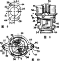
Fig. 1 is the partial top view of a kind of feed flow collector or feed pipe, is furnished with to longitudinal separation a plurality of spray nozzle assemblies of the present invention;
Fig. 2 is the partial longitudinal section view of Fig. 1 spray nozzle assembly along the amplification on the plane of 2-2 line;
Fig. 3 is the bottom view of the fog-spray nozzle of Fig. 2 spray nozzle assembly along the amplification on the plane of 3-3 line;
Fig. 4 is the perspective view of illustrated spray nozzle assembly;
Fig. 5 is the longitudinal cross-section view of Fig. 4 spray nozzle assembly along the amplification on the plane of 5-5 line;
Fig. 6 is the decomposition diagram of Fig. 5 spray nozzle assembly;
Fig. 7 is the front view of the fog-spray nozzle of Fig. 6 spray nozzle assembly;
Fig. 8 is the side view of the fog-spray nozzle of Fig. 6 spray nozzle assembly;
Fig. 9 is the viewgraph of cross-section of Fig. 7 fog-spray nozzle along the plane of 9-9 line, describes the locking of fog-spray nozzle and the configuring condition of the tenon of projection in detail;
Figure 10 is the bottom view of Fig. 7 fog-spray nozzle along the plane of 10-10 line;
Figure 11 is the end face view of Fig. 6 nozzle body;
Figure 12 and 13 is respectively the longitudinal cross-section view of Figure 11 nozzle body along the plane of 12-12 line and 13-13 line;
Figure 14 is the viewgraph of cross-section along the plane of the 14-14 line of Fig. 5, describes the locking tenon surface of fog-spray nozzle and the situation that engages of nozzle body in detail;
Figure 15 is the perspective view of another embodiment of spray nozzle assembly of the present invention;
Figure 16 is the plane of the nozzle body of Figure 15 along the plane of 16-16 line;
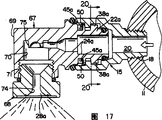
Figure 17 is the longitudinal cross-section view of the spray nozzle assembly of Figure 15 along the amplification on the plane of 17-17 line;
Figure 18 is the end face view of amplification of the band partial cross section of the fog-spray nozzle joint in Figure 15 spray nozzle assembly;
Figure 19 is the viewgraph of cross-section of Figure 18 fog-spray nozzle joint along the plane of 19-19 line, describes its locking tenon in detail;
Figure 20 is the viewgraph of cross-section along the plane of the 20-20 line of Figure 17, describes the locking tenon surface of fog-spray nozzle joint and the situation that engages of nozzle body in detail;
Figure 21 is the decomposition diagram of another embodiment of spray nozzle assembly of the present invention;
Figure 22 is nozzle body in Figure 21 spray nozzle assembly and the fog-spray nozzle joint plane along the plane of 22-22 line;
Figure 23 is the longitudinal cross-section view of Figure 22 spray nozzle assembly along the amplification on the plane of 23-23 line;
Figure 24 is the viewgraph of cross-section along the plane of the 24-24 line of Figure 23, describes the locking tenon surface of fog-spray nozzle joint and the joint situation of nozzle body in detail;
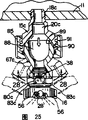
Figure 25 is the fragmentary sectional view of another embodiment of spray nozzle assembly of the present invention;
Figure 26 is the decomposition diagram that has partial cross section of the fog-spray nozzle joint of Figure 25 spray nozzle assembly;
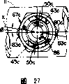
Figure 27 is the plan view of the nozzle body of Figure 26 along the plane of 27-27 line;
Figure 28 is the viewgraph of cross-section along the plane of the 28-28 line of Figure 25, describes the joint situation of the locking surface of fog-spray nozzle and joint in detail.
The specific embodiment
The present invention can have the structure of different versions and other, has shown some illustrative embodiment in the accompanying drawings and will be explained in detail below.But, should be appreciated that the present invention is not limited to given special shape, but opposite, the present invention can comprise that all fall into the present invention and conceive scope interior version, other structures and equivalent.
Now carefully consult the Fig. 1 in the accompanying drawing, it has described an illustrative spraying system 10, this system comprises a feed flow collector or a feed pipe 11 with a plurality of spray nozzle assemblies of the present invention, and said spray nozzle assembly longitudinal separation along collector 11 and installed.In some aspects, US patent 5,727,739 contents that disclosed of said spray nozzle assembly and Hamilton are similar, and the content disclosed in it will be introduced in this form with reference.Because each spray nozzle assembly structurally all is the same, therefore only one is described in detail.
Each spray nozzle assembly 12 consists essentially of a spray nozzle main body 15 and removable fog-spray nozzle or nozzle 16.This nozzle body 15 and fog-spray nozzle 16 both the most handy a kind of suitable corrosion-resistant plastics are made, and can make in production in enormous quantities equipment by injection moulding.This nozzle body 15 has end, a threaded upstream 18 in this example, in order to this nozzle body 15 is connected on the collector 11.A hexagon front portion 19 of main body 15 can make a spanner act on this nozzle body 15 so that this main body is fastened on the collector 11.There is a fluid passage that is limited by endoporus 20 inside of this nozzle body 15.Downstream in this hole, this main body 15 is formed with the annular compartment 21 of an increasing, in order to hold the end, upstream 22 of fog-spray nozzle 16.
The end, upstream 22 of this fog-spray nozzle 16 is formed with an internal flow through hole 24, and this through hole aligns with the internal flow through hole 20 of nozzle body 15.This fog-spray nozzle 16 also further comprise one leading to part 25, this defines a tube reducing hole 26 that communicates with hole 24 and ends at the front end that has nozzle 28, in this example, this nozzle is limited by a V-shape otch at targeting part 25 front ends, thus formed one have disperse side 29 elongated outlet producing a kind of flat cloudy surface of dispersing.
For the chamber 21 that makes nozzle body completely cuts off with external environment condition, said fog-spray nozzle 16 has a pair of ring-type O-shape potted component 30,31, and they are arranged in fog-spray nozzle 16 corresponding longitudinal separations and in the water jacket 34,35 the US patent 5 of the mode of layout and the reference of top institute, 727,739 is similar.Nozzle body 15 and fog-spray nozzle 16 all are formed with coefficient cam member, these cam members can axially be incorporated into this fog-spray nozzle 16 in the nozzle body 15 when fog-spray nozzle 16 inserts main body end to endly, and it is rotated with respect to nozzle body 15.As an annex on it, said potted component 30 is compressed between the inboard of the outside of fog-spray nozzle 16 and nozzle body 15, thereby form the sealing of first road, said potted component 31 then pressure leans against on the end of nozzle body 15, thereby forms the sealing of second road between fog-spray nozzle and nozzle body.
More particularly, the cam member of fog-spray nozzle 16 is to be stretched out and the opposed tenon 38 of diametric(al) constitutes by a pair of, and the end, upstream 22 of said tenon and fog-spray nozzle 16 is integrally formed.In the time of in fog-spray nozzle 16 is inserted into nozzle body 15 at first, the orientation of this head is such, promptly will with tenon 38 at a slant with main body in a pair ofly align at the opposed breach 39 of diametric(al).These breach 39 are limited to a pair of between the adjacent end portion of the opposed tenon 40 of diametric(al), said tenon and main body 15 integrally formed and to projecting inward from this main body.Said tenon 40 is separated with the axial relative shoulder 41 (Fig. 5 and 6) on the main body in the front, so just defines a groove 42 between shoulder and each tenon 40.
By above-mentioned layout, the tenon 38 on fog-spray nozzle 16 to align with the breach 39 in the main body 15 at first and in head is inserted into nozzle body the time by these breach.In case said tenon 38 passes breach 39 and crosses tenon 40, then can clockwise rotate fog-spray nozzle 16 about 1/4th circles so that tenon 38 enters groove 42.The relative cam surface of tenon 38,40 tilts, so that produce a kind of with the cam effect of head shaft in being incorporated into main body when head rotates in the clockwise direction.End wall or stop 43 (Figure 11-14) an end of each groove 42 and nozzle body is integrally formed and inwardly from protruding this main body so that this end of groove is closed.The respective stop face of tenon 38 (Fig. 7-9) or side 44 accurately are limited in 1/4th circles with engaging of end wall or stop 43 with clockwise rotating of fog-spray nozzle 16.
In order safely fog-spray nozzle 16 to be remained in the nozzle body 15, this fog-spray nozzle 16 and main body 15 all are formed with coefficient keeper on assembled relation, and those keepers in the US patent 5,727,739 of they and institute's reference are similar.More particularly, said fog-spray nozzle 16 is formed with two keepers 45 in the opposed side of fog-spray nozzle 16 diametric(al)s, and the shape of each all is the horizontal band or the rib of the plastics that extend out from shoulder 46.Because rib 45 is crooked, therefore between the concave surface of shoulder 46 and rib 45, define a space 47, this space can make rib 45 elastic deflection occur when responsive to axial force is arranged.The shape of the keeper in nozzle body 15 is depression or pit 50 (Figure 11-13), in shape with said rib 45 complementations, be formed in the downstream of tenon 40.
When clockwise rotating said fog-spray nozzle 16, make fog-spray nozzle tenon 38 come to cams on the nozzle body tenon 40, therefore, the downstream of rib 45 and tenon 40 enter interference fit and because of the permission that is subjected to space 47 to shoulder 46 deflections.When said fog-spray nozzle 16 arrived its abundant installation site, rib 45 was with nozzle body pit 50 oblique alignment and just flexibly enter into pit 50 once, counterclockwise rotation do not occur to keep fog-spray nozzle safely.Prepare fog-spray nozzle when main body 15 is unloaded down when rotating counterclockwise fog-spray nozzle 16, the guiding end of each rib 45 is carried out cam driven and deflection occurs leaving said pit by the adjacent flex end of corresponding pit 50.Like this, tenon 38 turns to breach 39 and aligns, so this fog-spray nozzle 16 gets loose, this just can make fog-spray nozzle separate from beginning to end with nozzle body.
For ease of catching and rotate fog-spray nozzle 16, this fog-spray nozzle 16 has an outer part 55 of grabbing of extending in the periphery, and it and targeting part 25 separate outside.Should outer grab part 55 is integrally formed parts of extending forward of said fog-spray nozzle 16, and comprises a pair of promptly wing 56 that radially extends, and is arranged on the opposed side of its diametric(al) so that the driving torque maximization.These are firmly grasped the wing 56 and are arranged in the cylindrical side wall 58 of targeting part 25 on the opposed side of diametric(al) equally and link to each other.
According to an important aspect of the present invention, the said promptly wing is radially aliging with the elongated outlet of fog-spray nozzle, so that pointed out the user and make its direction of knowing outlet before spray operation begins, thereby knows the direction of flat discharge cloudy surface.For this reason, in an illustrated embodiment, the said promptly wing 56 is V-shapes, and shown in Fig. 6 and 10, and the long transverse axis X extend past V-shape of outlet is firmly grasped the axis of the wing 56.The said promptly wing 56 is formed with some external vertical crestal lines 59 in this case so that catch.Can see that because these wings 56 are radially aliging with elongated outlet 28, therefore, even when outlet is difficult for seeing, the user also can easily know the direction of this outlet 28.
For realizing another feature of the present invention, the said promptly wing 56 has hollow-core construction, this structure qualification in the opposed clearance opening 60 of diametric(al) so that flat discharge cloudy surface pass through in the clear.In this illustrative embodiment, the promptly wing 56 of said grip portion 55 and cylindrical side wall 58 have one substantially uniformly, quite thin wall thickness, as shown in figure 10.Promptly the convergent face 57 of the wing 56 respectively defines the boring district or the opening 60 (Fig. 7) of a V-shape, they vertically align with elongated outlet 28, even do not disturb with the wing 56 promptly so that also can make the outer rim of the flat cloudy surface of discharge discharge spray nozzle under high volume/capacity spraying situation.
Be not subjected to the damage of external object or similar object because of contact for the outlet 28 of protecting fog-spray nozzle; the said promptly wing 56 is the tool tapering of direction forward in this case; as shown in Figure 7, distance ' ' d ' ' has exceeded the axial end portion of the targeting part 25 that is formed with outlet 28.In an illustrated embodiment, the tapering that the said promptly wing 56 has respectively forward in front and back side 61,62, it is last so that more easily contact and rotate that they are further used for that the said promptly wing 56 is positioned at distance very little before the nozzle body 15.
According to another characteristic of the invention, the clearance opening 60 that is limited by the wing 56 is promptly extending axially by firmly grasping the wing, to limit the flow channel parallel with the axis of spray nozzle assembly, said passage can make the axial flow of atmosphere through fog-spray nozzle 16, is accompanied by decomposition and distribution that spray process is strengthened liquid particles.In an illustrated embodiment, the cylindrical wall 58 of fog-spray nozzle grip portion 55 is integrally formed and partly extends out in the axial center main from fog-spray nozzle 16.On the other hand, the promptly wing 56 of V-shape stretches out from cylindrical side wall 58 and nozzle head main body with cantilevered fashion, so that limit V-shape opening or passage 60 on the opposed side of diametric(al) of the outlet 28 of nozzle head and Qi Nei.In use, particularly at a high speed/the capacity spray process in, air will be introduced into through said passage 60, the spray velocity that is accompanied by discharge improves nebulization efficiency, even can be full of the space of industrial environment.
For realizing another aspect of the present invention, spray nozzle assembly 12 can also be installed in addition and be used for the upwards collector 11 of vertical spraying, and the fog-spray nozzle 16 that does not use the liquid that can cause to fall and break to occur gathering, they may hinder the discharge of cloudy surface or form ugly drop.Be appreciated that and use orientation fog-spray nozzle 16 up, just define one in the grip portion 55 of fog-spray nozzle and the space between the targeting part 25 and have liquid and fall into zone in it.Through flow channel or opening that passage 60 that firmly grasping the wing further defines liquid, to prevent that fluid accumulation is in fog-spray nozzle.
As known in the art; often also need spray nozzle assembly 12 is installed on common collector or the feed pipe 11; and the orientation of the outlet 28 of each nozzle will make the flat cloudy surface of discharge and the longitudinal axis of feed flow collector 11 be predetermined low-angle; for example 10 spend; like this, conflict mutually will can not appear directly in the flat cloudy surface of adjacent nozzles assembly discharge.As Fig. 1 can see, promptly the orientation of the wing 56 can allow the user easily observe the direction of outlet, even at the close quarters that can not directly see outlet.
For further realizing the present invention, the nozzle body 15 of spray nozzle assembly 12 is formed with cue mark, when these marks vertically align with feed pipe or collector 11, the orientation of the outlet 28 of fog-spray nozzle will automatically form common predetermined, a less angle with collector 11.In an illustrated embodiment, each of said nozzle body 15 all has been formed separately cue mark nib 64,65 in the top and the bottom of its hexagon front portion 19.The interlocking tenon 38,40 of nozzle body 15 and fog-spray nozzle 16 is designed to when nozzle head 15 is installed nib 64,65 vertically be alignd with collector 11, as shown, when tenon stop surface 44 engaged with the stop 43 of main body, the orientation of the fog-spray nozzle 16 of assembling made No Exit 28 be the angle of 10 degree with respect to collector.Thus, the installation of nozzle body 15 on collector 11 will make cue mark bead 64,65 vertically align with collector 11, this outlet 28 that will automatically make fog-spray nozzle is required predetermined angular with respect to the orientation of collector, and this is easy to observe out from the promptly orientation of the wing 56 of fog-spray nozzle.
For realizing another feature of the present invention, fog-spray nozzle is firmly grasped the wing 56 and is arranged to be vertical with keeper 45 or 90 degree biasings with respect to tenon 38, so that injection moulding.As shown in Figure 6, the wing 56 aligns with the X-axis line that is horizontally through fog-spray nozzle in order to make promptly, and the z axis that the locking tenon 38 of fog-spray nozzle and stop surface 44 thereof are parallel to fog-spray nozzle extends, as described in Fig. 6 and 10.Those skilled in the art will appreciate that the fog-spray nozzle locking tenon stretched and promptly this vertical orientated of the wing can the injection-moulding plastic mould removed and local interference do not occur according to Mould operation.Therefore in practice, this fog-spray nozzle can be used as disposable use part and carries out commerce manufacturing, so that can regularly replace fog-spray nozzle when needed.According to above-mentioned referenced patent 5,727,739 described contents are because flexible keeper is on fog-spray nozzle, therefore, the result person of being to use who at every turn changes used fog-spray nozzle with a new head has obtained a nozzle assembly with good location characteristic with new flexible keeper.
Simultaneously, as mentioned above, said spray nozzle assembly 12 is applicable to that fog-spray nozzle automatically is orientated along X-axis, therefore, being accompanied by fog-spray nozzle 16 is installed in the nozzle body, outlet 28 is a less predetermined angular with respect to the axis of feed flow collector 11, needs sometimes fog-spray nozzle is mounted to respect to the feed flow collector to have different angles, for example for the right angle spraying.So far, the spray nozzle assembly of different spray applications and personalized design all are quite expensive concerning processing with making.
According to a further general feature of the present invention, said nozzle body is applicable to and holds the fog-spray nozzle with first kind of design locking tenon, as implied above, to be the X-axis line of fog-spray nozzle and outlet have a less angle with respect to the longitudinal axis of feed flow collector to the orientation of this fog-spray nozzle, and on the other hand, be applicable to and hold and the fog-spray nozzle that has a little locking tenon that change or second kind of design is installed, the X-axis that this design is suitable for fog-spray nozzle is orientated the situation that is parallel to feed pipe, the spraying face of making is discharged with different angles with respect to header axis, for example 90 degree.With reference to figure 15-20, shown a spray nozzle assembly, it has a nozzle body 15 identical with above-mentioned nozzle body and a spray nozzle 66, in this case, it is used for discharging a kind of open circles taper cloudy surface on the direction of collector 11 longitudinal axis that nozzle body 15 vertically is housed thereon.Shown in the above-described embodiments, the nozzle body 15 that is installed on the collector 11 will vertically align the cue mark nib on it 64,65 with said collector 11.
Said spray nozzle 66 has a kind of two-part construction in this case, this structure comprises a quick-release coupling 67 and spout cap or plug 68, as shown in figure 17, and wherein, what the part identical with above-mentioned those parts provided is identical reference number, and difference is to have added suffix " a ".This quick-release coupling 67 has a upstream portion 22a, is formed with an internal flow through hole 24a who aligns with the internal flow through hole 20 of nozzle body 15.This joint 67 also further comprises a front portion 69, is formed with a minor air cell 70 that communicates with fluid through-hole 24a with the tangent line right angle.This front connector part 69 has a female end 71, is used to hold the end of thread of spout cap 68, and this spout cap is formed with one at the outlet 28a that axially communicates with minor air cell 70.The tap 28a of described spout cap 68 comprise one from the minor air cell 70 outward extending excurvation wall parts 74, this part can change according to required spray shapes.This joint 67 has an integrally formed setting post 75 that 70 bottom extends out from the minor air cell, and the liquid that is used for introducing is directed in the minor air cell 70, as be known in the art like that.
Install for ease of the quick-release of joint 67 in main body 15, end, the upstream 22a of said joint is formed with and paired stretches out and at opposed projection locking tenon 38a of diametric(al) and keeper 45a, they are similar with keeper 45 to the tenon 38 of above-mentioned fog-spray nozzle 16, are designed to be inserted in the nozzle body 15 and turn to and the nozzle body locked engagement.Similar to fog-spray nozzle 16, locking tenon 38 has stop surface 44a, and the Z axle that is parallel to the mounting end 22a of this joint extends, as shown in figure 19.
For realizing this one side of the present invention, has only very little variation in design, the locking tenon 38a of joint is used for spray nozzle 66 location and is locked at main body 15, the X-axis line parallel that makes nozzle connection 67 is in collector 11, like this, the eddy current cloudy surface of discharging from nozzle is perpendicular to the longitudinal axis of (promptly 90 spend) collector 11.For this reason, shown in Figure 19-20, the distance that the stop surface 44a of the locking tenon 38a of said joint 67 setovers with respect to the Z axle side direction of nozzle on the rotation direction of installation process is a bit larger tham the stop surface 44 of fog-spray nozzle 16.In other words, with reference to figure 9 and 14, can see, the stop surface 44 of fog-spray nozzle tenon 38 is " 1 " in that the distance of setovering from the Z axle of fog-spray nozzle 16 on the rotation direction is installed, the stop surface 44a of the locking tenon 38a of quick-release coupling 67 then is positioned at a bigger distance " 1 adds x ", shown in Figure 19 and 20.
Because the larger side of the stop surface 44a of nozzle 66 is compared with the tenon 38 of fog-spray nozzle 16 to biasing, this tenon 38a will engage with the stop 43 of main body 15 earlier.As can seeing among Figure 14, fog-spray nozzle 16 turns to said tenon stop surface 44 basically Face to face with till main body stop 43 engages always in main body 15.Because the larger side of the tenon stop surface 44a in the nozzle 66 is to biasing, as seeing among Figure 20, this tenon stop surface 44a will contact with main body stop 43 before entering face-to-face completely the joint, and like this, this tenon stop surface 44a engages at a slant with respect to main body stop 43.By be nozzle 66 suitably the design additional side to biasing " x ", those skilled in the art will recognize, the rotation of nozzle 66 is installed and can be stopped under the longitudinal axis situation of feed flow collector 11 at the X-axis line parallel of nozzle 66, rather than is at fog-spray nozzle 16 under the situation of 10 degree biasings.Because the outlet 28a of minor air cell is designed so that the cloudy surface and the X-axis line of discharging are 90 degree, therefore when quick-release coupling 67 was installed in the main body, outlet 28a automatically was orientated to the cloudy surface of discharging perpendicular to feed flow collector 11.Because additional offset or dish " x " can be quite little, for example about .056 inch will be so the keeper 45a of this joint also will fully engage so that quick-release coupling 67 forwards are remained on the installation site with the keeper 50 of main body.
Thus, it will be appreciated by those skilled in the art that, when said general main body 15 is installed on the collector 11 in the mode with the axial alignment of its cue mark nib 64,65 and collector 11, can hold a fog-spray nozzle 16 and make the direction of elongated flat spraying outlet 28 and header axis be a quite little angle of eccentricity, for example 10 spend, or on the other hand, can hold one second nozzle, as nozzle 66, make the direction of discharging cloudy surface be different angles, for example 90 degree with respect to header axis.Because fog-spray nozzle 16 and joint 67 both locking tenon 38,38a and stop 44, the direction of 44a all are parallel to the same z axis of head or joint, therefore, both structures are convenient to these parts and are carried out injection-moulding plastic, allow to carry out the processing of extracting from mould and can not be subjected to undercut surface or analog and disturb.But because very little in the structural difference of locking tenon, therefore employed is similar basically processing.
With reference now to Figure 21-24,, here the another kind of embodiment that has shown the spray nozzle assembly, it is suitable for commercial manufacturing and is suitable for using multiple various criterion fog-spray nozzle, wherein, what provide with above-mentioned those element components identical is identical reference number, and difference is to have added suffix " b ".This spray nozzle assembly comprises a nozzle body 15 and a detachable and removable spray nozzle 66b.The nozzle body 15 identical with the nozzle body of previous embodiment is installed on the feed flow collector 11 equally, the longitudinal axis alignment of its cue mark nib 64,65 and collector 11.This spray nozzle 66b comprises a quick-release coupling 67b in this case, and this quick-release coupling has the mounting portion, upstream or the end 22b that have tenon 38b and keeper 45b, and it is similar to the mounting end 22 of above-mentioned fog-spray nozzle 16.This quick-release coupling 67b has a downstream 69b, be formed with on it many vertically and circumferentially spaced promptly ribs 80 so that butt joint 67b handles and its rotation is installed in the main body 15.
This embodiment importance according to the present invention, the structure of this joint 67b are adapted to the standard fog-spray nozzle plug 68b of multiple required spray applications.For this reason, the downstream of this joint is formed with an internal thread chamber 71b, and this chamber communicates with the upstream internal flow through hole 24b of this joint 67b and is designed for holding the screw neck 81 of a standard fog-spray nozzle plug 68b.Because any required fog-spray nozzle plug 68b can be assembled among this joint 67b, therefore, by using general nozzle body 15 and joint 67b, this spray nozzle assembly can easily be applicable to special purposes.Can also recognize that when main body 15 and joint 67b preferably were molded out of plastic type, said fog-spray nozzle plug 68b also can be plastics or metal in case of necessity.
For further realizing this embodiment of the present invention, so that carry out directed in advance to the outlet 28b of selected fog-spray nozzle plug 68b in the spray nozzle assembly, said joint 67b is formed with cue mark 83, in this case, these cue marks are determined extending axially by the opposed promptly rib of diametric(al) 80.The structure of said joint 67b is like this design, promptly when turning to its installation site in main body 15, and the cue mark 83 of this joint and the cue mark of main body 64,65 on the X-axis line, align (Figure 22).Can recognize, because this cue mark 64,65,83 is arranged, so, before nozzle 66b is installed in the main body 15, said fog-spray nozzle plug 68b can make outlet 28b be screwed in the main body by predetermined orientation with respect to joint cue mark 83, and this itself also can make the orientation of fog-spray nozzle outlet 28b formation with respect to nozzle body 15 and feed flow collector 11.In this example, identical with above-mentioned fog-spray nozzle 16, the locking tenon face 44b of joint engages with main body stop 43, as shown in figure 24.Such nozzle assembly can not only be easily and accurately the outlet 28a of fog-spray nozzle plug is carried out orientation, and can carry out commercial exploitation to many dissimilar standard fog-spray nozzle plug 68b, thereby does not increase personalized design and processing cost.
With reference now to Figure 25-28,, here shown a kind of quick-release spray nozzle assembly that rotates installation of the present invention, still install with respect to feed flow collector 11, wherein, what parts identical with above-mentioned those parts or element or element provided is identical reference number, and difference is to have added suffix " b ".This spray nozzle assembly comprises a main body 15c, a joint 67c, a quick-release fog-spray nozzle 16 and a clamping cap 85 that is installed among the joint 67c in this case, said joint is mounted to and can selectively rotates the location in main body 15c, and said clamping cap is used for movably joint 67c being clamped in the required installation site of main body.The downside that is installed in feed flow collector 11 of nozzle body 15c is positioned at a vertical nipple joint 18c in the collector 11.In order to make liquid freely flow to fog-spray nozzle 16 from collector 11, said main body 15c and joint 67c are formed with communication passage 20c, 88.
For can with respect to main body selectively butt joint 67c be rotated the location, said main body 15c is formed with a spherical axis hole 89 at its downside, is used to hold the spherical installation end 90 of joint 67c.For joint 67c is clamped on the selected position, said clamping cap 85 can be threaded with the male thread portion 91 of main body 15c.For ease of manipulation and the rotation of joint 67c, this joint 67c is formed with many circumferentially spaced rib 80c that vertically firmly grasp.For fog-spray nozzle 16 quick-releases being installed among the joint 67c, this joint 67c is the same with fog-spray nozzle 16 with above-mentioned nozzle body 15 with fog-spray nozzle 16, is formed with coefficient tenon 40c, 38 and keeper 50c, 45.In fact, this fog-spray nozzle can be the same with aforesaid fog-spray nozzle 16.
For realizing this embodiment of the present invention, make fog-spray nozzle 16 assemblies be predetermined angular relationship with respect to feed flow collector 11, this joint 67c is formed with cue mark 83c, in this case, they by two among the opposed promptly rib 80c of diametric(al) promptly rib extend vertically and limit.This joint 67c and fog-spray nozzle 16 are designed to like this, and promptly when being installed to fog-spray nozzle 16 among the joint 67c, the outlet 28 of this joint 16 is predetermined angular relationship with respect to the cue mark nib 83c of this joint 67c, for example the biasing of 10 degree.Thus, the cue mark nib 83c that guarantees the joint 67c in main body 15c aligns with feed flow collector 11, as shown in figure 27, when being installed to fog-spray nozzle in the joint, will make the outlet 28 of fog-spray nozzle 16 automatically be predetermined angular relationship (Figure 28) with respect to collector.
From as can be known above-mentioned, spray nozzle assembly of the present invention can be fast and accurately with respect to feed pipe or collector forms predetermined orientation and can make the user just observe the suitable orientation of fog-spray nozzle outlet at an easy rate before spray operation.When fog-spray nozzle comprised promptly the wing, they just provided the indication that can easily observe the outlet orientation, and neither hindered and discharge flat cloudy surface and also do not hinder the decomposition of strengthening liquid particles and distribute required atmosphere inwardly to flow.
Said shower nozzle also further is designed to be suitable for commercial the manufacturing and disposable use, and maybe can be mounted to downward direction with respect to a feed flow collector or feed pipe and spray and maybe can be mounted to upward to spraying.Spray nozzle assembly of the present invention can also be applicable to that commercial different make direct fluid fog-spray nozzle or nozzle install and change in the spray applications with predetermined orientation at an easy rate with respect to the feed flow collector.
Claims (7)
1. spraying system, it comprises the fluid supply collector of a longitudinal extension, one group is used for being installed in spray nozzle assembly on the said collector to what the liquid that imports through said collector was sprayed, said spray nozzle assembly comprises that respectively is fixed on a nozzle body that is communicated with its fluid on the said collector, a fog-spray nozzle, being accompanied by said fog-spray nozzle turns on the abundant installation site with respect to said main body, this fog-spray nozzle can releasably be installed on the said main body, the said fog-spray nozzle of each spray nozzle assembly all has an elongated outlet, this outlet is along long transverse axis orientation and be used to spray a kind of flat cloudy surface, the said nozzle body of each spray nozzle assembly has unique a pair of at the opposed cue mark of diametric(al) on its at least one axle head, said nozzle body is installed on the said collector, said cue mark vertically aligns with said collector, the said elongated outlet of the fog-spray nozzle of each nozzle assembly on said abundant installation site then the longitudinal axis of said relatively collector be orientated with same predetermined smaller angle.
2. according to the spraying system of claim 1, wherein, each said nozzle body comprises a pair of at the opposed cue mark of diametric(al) on its top of vertically aliging with said collector respectively and bottom.
3. according to the spraying system of claim 1, wherein, said cue mark is the nib of projection integrally formed on said nozzle body.
4. according to the spraying system of claim 1, wherein, said fog-spray nozzle has at the opposed outward extending radially wing promptly that aligns with the major axis of said outlet of diametric(al), is used to indicate the direction of outlet and need not directly sees said outlet.
5. according to the spraying system of claim 4, wherein, the promptly wing of each fog-spray nozzle all defines arranges the clearance opening of its elongated outlet on the opposed abutting end of diametric(al).
6. according to the spraying system of claim 1, wherein, the promptly wing of each fog-spray nozzle all defines the passage that axially passes fog-spray nozzle on the opposed side of nozzle body.
7. according to the spraying system of claim 6, wherein, the said promptly wing has a V-shape cross section, and it defines the passage that axially passes fog-spray nozzle.
Applications Claiming Priority (2)
| Application Number | Priority Date | Filing Date | Title |
|---|---|---|---|
| US09/491132 | 2000-01-26 | ||
| US09/491,132 US6398128B1 (en) | 2000-01-26 | 2000-01-26 | Quick disconnect nozzle assembly |
Related Parent Applications (1)
| Application Number | Title | Priority Date | Filing Date |
|---|---|---|---|
| CNB01111648XA Division CN1210109C (en) | 2000-01-26 | 2001-01-26 | Quick detachable nozzle assembly |
Publications (2)
| Publication Number | Publication Date |
|---|---|
| CN1680043A CN1680043A (en) | 2005-10-12 |
| CN100340349C true CN100340349C (en) | 2007-10-03 |
Family
ID=23950921
Family Applications (2)
| Application Number | Title | Priority Date | Filing Date |
|---|---|---|---|
| CNB2005100712562A Expired - Lifetime CN100340349C (en) | 2000-01-26 | 2001-01-26 | Quick disconnect nozzle assembly |
| CNB01111648XA Expired - Lifetime CN1210109C (en) | 2000-01-26 | 2001-01-26 | Quick detachable nozzle assembly |
Family Applications After (1)
| Application Number | Title | Priority Date | Filing Date |
|---|---|---|---|
| CNB01111648XA Expired - Lifetime CN1210109C (en) | 2000-01-26 | 2001-01-26 | Quick detachable nozzle assembly |
Country Status (6)
| Country | Link |
|---|---|
| US (1) | US6398128B1 (en) |
| JP (1) | JP4863552B2 (en) |
| CN (2) | CN100340349C (en) |
| CA (1) | CA2332072C (en) |
| DE (1) | DE10103219A1 (en) |
| IT (1) | ITTO20010068A1 (en) |
Families Citing this family (50)
| Publication number | Priority date | Publication date | Assignee | Title |
|---|---|---|---|---|
| US6289455B1 (en) * | 1999-09-02 | 2001-09-11 | Crypotography Research, Inc. | Method and apparatus for preventing piracy of digital content |
| US6244527B1 (en) * | 2000-01-26 | 2001-06-12 | Spraying Systems Co. | Quick disconnect nozzle assembly |
| US6398128B1 (en) * | 2000-01-26 | 2002-06-04 | Spraying Systems Co. | Quick disconnect nozzle assembly |
| KR100375637B1 (en) * | 2000-10-27 | 2003-03-10 | 미래산업 주식회사 | Nozzle Apparatus of Surface Mount Device |
| DE10222610C2 (en) * | 2001-05-18 | 2003-04-10 | Dieter Gobbers | Sprayer for introducing or applying substances into or on the body |
| DE10142228A1 (en) * | 2001-08-29 | 2003-04-30 | Itw Oberflaechentechnik Gmbh | Fluid injection device |
| US20040227021A1 (en) * | 2003-05-16 | 2004-11-18 | Bowles Fluidics Corporation | Tool-free, quick disconnect, nozzle assembly |
| US6880768B2 (en) * | 2003-07-30 | 2005-04-19 | Jing Mei Industrial Holdings Limited | Handheld spraying device with quick disconnect assembly |
| US7083120B2 (en) * | 2003-11-04 | 2006-08-01 | Briggs & Stratton Power Products Group, Llc | Pressurized fluid delivery apparatus |
| US7032832B2 (en) * | 2003-12-16 | 2006-04-25 | Spraying Systems Co. | Asymmetrical spray nozzle with alignment notch |
| KR200344321Y1 (en) * | 2003-12-22 | 2004-03-09 | 주식회사 젯텍 | Ultra High Pressure Fan Jet Nozzle for a Deflashing Apparatus |
| KR100558579B1 (en) * | 2003-12-31 | 2006-03-13 | 삼성광주전자 주식회사 | Hose locking apparatus for vacuum cleaner |
| WO2005115633A2 (en) * | 2004-05-25 | 2005-12-08 | Nordson Corporation | Spray nozzle with alignment key for asymmetrical spray pattern |
| US20060196967A1 (en) * | 2005-03-03 | 2006-09-07 | Monty Daniel D | Nozzle for pressure washer or liquid sprayer |
| US20070131792A1 (en) * | 2005-12-14 | 2007-06-14 | Eastway Fair Company Limited Of Trident Chambers | Spray nozzle shroud |
| US20080053495A1 (en) * | 2006-09-06 | 2008-03-06 | Emp Advanced Development, Llc | Fluid cleaning system |
| TW201000213A (en) * | 2008-05-15 | 2010-01-01 | Graco Minnesota Inc | Quarter turn side seal assembly |
| DE102008055518A1 (en) * | 2008-12-12 | 2010-06-17 | Bühler AG | joint |
| EP2552594A4 (en) | 2010-04-02 | 2016-06-29 | Sta Rite Ind Llc | Air aspiration device |
| US8721747B2 (en) * | 2010-08-11 | 2014-05-13 | General Electric Company | Modular tip injection devices and method of assembling same |
| CN103752451A (en) * | 2010-11-30 | 2014-04-30 | 喷雾咀工程股份有限公司 | Insert assembly used for spray nozzle assembly |
| US9010660B2 (en) | 2011-06-13 | 2015-04-21 | Nelson Irrigation Corporation | Integrated sprinkler head multi-nozzle/shut-off system |
| US8910888B2 (en) | 2011-07-25 | 2014-12-16 | Nelson Irrigation Corporation | Sprinkler linear side-load, multi-nozzle system |
| US8888143B2 (en) * | 2011-09-23 | 2014-11-18 | Diba Industries, Inc. | Torque limiting fastening assemblies and fluid coupling assemblies including the same |
| US9089857B2 (en) | 2011-09-29 | 2015-07-28 | Nelson Irrigation Corporation | Side load sprinkler nozzle system |
| JP5796847B2 (en) * | 2012-03-08 | 2015-10-21 | 日鐵住金溶接工業株式会社 | Insert tip and plasma torch |
| US9095859B2 (en) | 2012-06-01 | 2015-08-04 | Nelson Irrigation Corporation | Multi-nozzle shuttle for a sprinkler head |
| DE102012108697A1 (en) * | 2012-09-17 | 2014-03-20 | Krones Ag | Spraying nozzle for beverage filling system, has nozzle head for application of medium on area of filling system and connected with nozzle carrier in detachable manner over bayonet fitting, where fitting is arranged within carrier |
| KR200468504Y1 (en) * | 2012-12-05 | 2013-08-19 | 훈 최 | Atomizing nozzle assembly for printed circuit board processing device |
| US9403177B2 (en) | 2013-06-26 | 2016-08-02 | Nelson Irrigation Corporation | Sprinkler with multi-functional, side-load nozzle |
| US20160375457A1 (en) * | 2013-06-26 | 2016-12-29 | Nelson Irrigation Corporation | Sprinkler with multi-functional, side-load nozzle with nozzle storage clip and related tool |
| US9534619B2 (en) | 2013-06-26 | 2017-01-03 | Nelson Irrigation Corporation | Sprinkler with multi-functional, side-load nozzle with nozzle storage clip and related tool |
| US9283577B2 (en) | 2013-06-26 | 2016-03-15 | Nelson Irrigation Corporation | Sprinkler with multi-functional, side-load nozzle |
| JP6091375B2 (en) * | 2013-08-09 | 2017-03-08 | 株式会社ジーシー | Nozzle tip |
| US9387494B2 (en) | 2013-10-10 | 2016-07-12 | Nelson Irrigation Corporation | Sprinkler with multi-functional, side-load nozzle insert with ball-type valve |
| DE102014205399B3 (en) * | 2014-03-24 | 2015-09-10 | Lechler Gmbh | injector nozzle |
| JP2016019954A (en) * | 2014-07-15 | 2016-02-04 | 株式会社いけうち | Detachable spray nozzle |
| CN104353565B (en) * | 2014-10-31 | 2017-07-18 | 嘉善县康民实业有限公司 | A kind of flusher of weaving |
| PT3277077T (en) * | 2015-04-01 | 2022-08-05 | Spraying Systems Co | Spray nozzle assembly with expanded pressure responsive liquid flow rate control |
| US9687860B2 (en) | 2015-08-18 | 2017-06-27 | Delta Faucet Company | Quick connect showerhead |
| CN105080747B (en) * | 2015-09-11 | 2017-05-31 | 南通市乐悦实业有限公司 | A kind of constant-temp. and-moisture maintenance sparge pipe |
| CN105597983B (en) * | 2016-03-09 | 2017-12-08 | 绍兴万宇纺织有限公司 | A kind of more shower nozzle connection pipe body of convenient disassembly |
| WO2017177082A1 (en) * | 2016-04-07 | 2017-10-12 | Spraying Systems Co. | Shower header spray system |
| JP6184554B1 (en) * | 2016-05-24 | 2017-08-23 | ヤマホ工業株式会社 | Nozzle assembly with removable cap |
| CA3037418C (en) * | 2016-09-19 | 2023-09-05 | Spraying Systems Co. | Spray nozzle assembly with one piece spray nozzle and quick disconnect retention cap |
| US10765103B2 (en) | 2017-06-05 | 2020-09-08 | The Board Of Trustees Of The University Of Arkansas | Spray nozzle system |
| WO2019195927A1 (en) * | 2018-04-12 | 2019-10-17 | Les Entreprises Francois Masse Inc. | Adapter for selectively connecting an accessory to a spray gun |
| JP7317661B2 (en) * | 2019-04-10 | 2023-07-31 | 株式会社ハミルセレナ | Urethane Foam Spray Dispensing Gun |
| DE102021106359A1 (en) * | 2021-03-16 | 2022-09-22 | Khs Gmbh | Spray nozzle arrangement for a spray station and nozzle body for a spray nozzle of a spray nozzle arrangement |
| DE102021106372A1 (en) * | 2021-03-16 | 2022-09-22 | Khs Gmbh | Spray nozzle arrangement for a spray device, spray device with a spray nozzle arrangement and nozzle body for a spray nozzle arrangement |
Citations (6)
| Publication number | Priority date | Publication date | Assignee | Title |
|---|---|---|---|---|
| US4527745A (en) * | 1982-05-28 | 1985-07-09 | Spraying Systems Co. | Quick disconnect fluid transfer system |
| US5000675A (en) * | 1990-02-09 | 1991-03-19 | Mold-Masters Limited | Injection molding manifold and nozzle having laterally clamped flanges |
| US5190224A (en) * | 1990-04-05 | 1993-03-02 | Spraying Systems Co. | Quick disconnect nozzle assembly |
| US5253807A (en) * | 1992-03-17 | 1993-10-19 | Wade Manufacturing Co. | Multi-outlet emitter and method |
| US5333794A (en) * | 1991-06-14 | 1994-08-02 | Spraying Systems Co. | Spray nozzle with recessed deflector surface and mounting assembly thereof |
| US5727739A (en) * | 1995-03-03 | 1998-03-17 | Spraying Systems Co. | Nozzle with quick disconnect spray tip |
Family Cites Families (11)
| Publication number | Priority date | Publication date | Assignee | Title |
|---|---|---|---|---|
| US4664314A (en) | 1982-10-01 | 1987-05-12 | Spraying Systems Co. | Whirl spray nozzle |
| DK135090A (en) * | 1990-05-31 | 1991-12-01 | Hardi Int As | SPRAY NOZZLE |
| JP2532323Y2 (en) * | 1990-10-26 | 1997-04-16 | 株式会社いけうち | nozzle |
| US5143298A (en) | 1990-10-31 | 1992-09-01 | Man Roland Druckmaschinen Ag | Spray nozzle assembly with swivel mounted hollow cone spray tip |
| US5295506A (en) * | 1992-12-14 | 1994-03-22 | Smith Allan L | Flow control apparatus |
| US5421422A (en) | 1993-11-19 | 1995-06-06 | Boretec Inc | Roller cutter mount for tunneling machine |
| US5642860A (en) * | 1995-07-07 | 1997-07-01 | The Procter & Gamble Company | Pump sprayer for viscous or solids laden liquids |
| EP0822863A1 (en) * | 1996-02-27 | 1998-02-11 | Spraying Systems Co. | Nozzle with quick disconnect spray tip |
| US6079638A (en) * | 1998-07-20 | 2000-06-27 | Chang; Sei-Chang | Nozzle assembly improvement |
| JP4316740B2 (en) * | 1999-09-01 | 2009-08-19 | 株式会社アサヒペン | Nozzle tip for elliptical injection of aerosol button |
| US6398128B1 (en) * | 2000-01-26 | 2002-06-04 | Spraying Systems Co. | Quick disconnect nozzle assembly |
-
2000
- 2000-01-26 US US09/491,132 patent/US6398128B1/en not_active Expired - Lifetime
-
2001
- 2001-01-24 CA CA002332072A patent/CA2332072C/en not_active Expired - Lifetime
- 2001-01-25 DE DE10103219A patent/DE10103219A1/en not_active Ceased
- 2001-01-26 CN CNB2005100712562A patent/CN100340349C/en not_active Expired - Lifetime
- 2001-01-26 IT IT2001TO000068A patent/ITTO20010068A1/en unknown
- 2001-01-26 CN CNB01111648XA patent/CN1210109C/en not_active Expired - Lifetime
- 2001-01-26 JP JP2001018982A patent/JP4863552B2/en not_active Expired - Lifetime
Patent Citations (6)
| Publication number | Priority date | Publication date | Assignee | Title |
|---|---|---|---|---|
| US4527745A (en) * | 1982-05-28 | 1985-07-09 | Spraying Systems Co. | Quick disconnect fluid transfer system |
| US5000675A (en) * | 1990-02-09 | 1991-03-19 | Mold-Masters Limited | Injection molding manifold and nozzle having laterally clamped flanges |
| US5190224A (en) * | 1990-04-05 | 1993-03-02 | Spraying Systems Co. | Quick disconnect nozzle assembly |
| US5333794A (en) * | 1991-06-14 | 1994-08-02 | Spraying Systems Co. | Spray nozzle with recessed deflector surface and mounting assembly thereof |
| US5253807A (en) * | 1992-03-17 | 1993-10-19 | Wade Manufacturing Co. | Multi-outlet emitter and method |
| US5727739A (en) * | 1995-03-03 | 1998-03-17 | Spraying Systems Co. | Nozzle with quick disconnect spray tip |
Also Published As
| Publication number | Publication date |
|---|---|
| JP4863552B2 (en) | 2012-01-25 |
| CN1680043A (en) | 2005-10-12 |
| DE10103219A1 (en) | 2001-08-09 |
| CN1210109C (en) | 2005-07-13 |
| CA2332072C (en) | 2009-09-15 |
| CN1325761A (en) | 2001-12-12 |
| CA2332072A1 (en) | 2001-07-26 |
| ITTO20010068A0 (en) | 2001-01-26 |
| JP2001259483A (en) | 2001-09-25 |
| US6398128B1 (en) | 2002-06-04 |
| ITTO20010068A1 (en) | 2002-07-26 |
Similar Documents
| Publication | Publication Date | Title |
|---|---|---|
| CN100340349C (en) | Quick disconnect nozzle assembly | |
| US4738401A (en) | Quick disconnect nozzle assembly with twist-on spray tip | |
| US6193172B1 (en) | Swirl unit, orifice plate, and spray nozzle including same | |
| CN1178851C (en) | Gravity feed fluid dispensing valve | |
| CN1080596C (en) | Dual fluid spray nozzle | |
| US8961640B2 (en) | Filter | |
| CN1030881A (en) | A kind of injection apparatus that is provided with an additive fluid dispenser in the port of export | |
| CN101237940A (en) | Nozzle for a spray head | |
| CN107213703B (en) | Efficient desulfurizing tower | |
| MX2015002057A (en) | Full cone air-assisted spray nozzle assembly. | |
| CN116921092A (en) | Spray gun base body, spray gun set, method for manufacturing base body and refitting spray gun | |
| KR102188047B1 (en) | spray nozzle of reagent for blood collection tube | |
| CN203765107U (en) | Gear hole self-centering ball fixture | |
| CN201120335Y (en) | Showerhead apparatus for abrasive material water-jet cutting machine | |
| CN206935077U (en) | Denitration pipette tips | |
| CN201195138Y (en) | A nozzle | |
| CA2428718A1 (en) | Antislip material ejector | |
| CN217459351U (en) | Pressure pipe subsides device | |
| CN220546964U (en) | Gas-liquid reverse rotation reinforced mass transfer reaction tower | |
| US3773257A (en) | Fountain nozzles for generating plural unaerated water streams | |
| CN214295924U (en) | Sand box quick sand discharging device | |
| CN204429121U (en) | For the connection device of gas-liquid mixed instrument | |
| CN202506542U (en) | Powder flow divider | |
| CN216078741U (en) | 110-degree rotary joint | |
| CN205851127U (en) | Anti-eccentric cap of spraying nozzle on spray valve |
Legal Events
| Date | Code | Title | Description |
|---|---|---|---|
| C06 | Publication | ||
| PB01 | Publication | ||
| C10 | Entry into substantive examination | ||
| SE01 | Entry into force of request for substantive examination | ||
| C14 | Grant of patent or utility model | ||
| GR01 | Patent grant | ||
| C56 | Change in the name or address of the patentee |
Owner name: SPRAYING SYSTEM CO., LTD. Free format text: FORMER NAME: SPRAY SYSTEMS INC. |
|
| CP01 | Change in the name or title of a patent holder |
Address after: Illinois State Patentee after: Spraying Systems Co. Address before: Illinois State Patentee before: Spray Systems Inc. |
|
| CX01 | Expiry of patent term |
Granted publication date: 20071003 |
|
| CX01 | Expiry of patent term |