CN1003356B - Method and equipment for continously making strip materials under high temp. - Google Patents
Method and equipment for continously making strip materials under high temp. Download PDFInfo
- Publication number
- CN1003356B CN1003356B CN86106003.2A CN86106003A CN1003356B CN 1003356 B CN1003356 B CN 1003356B CN 86106003 A CN86106003 A CN 86106003A CN 1003356 B CN1003356 B CN 1003356B
- Authority
- CN
- China
- Prior art keywords
- sealing device
- increased pressure
- zone
- pressure board
- pressure
- Prior art date
- Legal status (The legal status is an assumption and is not a legal conclusion. Google has not performed a legal analysis and makes no representation as to the accuracy of the status listed.)
- Expired
Links
Images


Classifications
-
- B—PERFORMING OPERATIONS; TRANSPORTING
- B30—PRESSES
- B30B—PRESSES IN GENERAL
- B30B5/00—Presses characterised by the use of pressing means other than those mentioned in the preceding groups
- B30B5/04—Presses characterised by the use of pressing means other than those mentioned in the preceding groups wherein the pressing means is in the form of an endless band
- B30B5/06—Presses characterised by the use of pressing means other than those mentioned in the preceding groups wherein the pressing means is in the form of an endless band co-operating with another endless band
- B30B5/062—Presses characterised by the use of pressing means other than those mentioned in the preceding groups wherein the pressing means is in the form of an endless band co-operating with another endless band urged by directly-acting fluid pressure
Landscapes
- Physics & Mathematics (AREA)
- Fluid Mechanics (AREA)
- Engineering & Computer Science (AREA)
- Mechanical Engineering (AREA)
- Press Drives And Press Lines (AREA)
- Casting Or Compression Moulding Of Plastics Or The Like (AREA)
Abstract
In a double-band press for the continuous pressing of material webs which require hardening temperatures which are too high to be withstood by the seals of pressure chambers in the double-band press, a pressure plate of the double-band press is divided into an edge area and an inner area, with the edge area having a temperature which is capable of being withstood by the seal material, while the inner area is heated to an increased temperature suitable for processing the material webs. During operation of the apparatus, heat is conducted from the inner area to a portion of the press belt lying against it. The pressure plate is formed with a rectangular recess in which is arranged a pressure plate insert forming the inner area. The pressure plate insert is heated and includes thermal conducting elements which transfer heat to the press belt.
Description
The present invention relates to a kind of two warmed-up non junctions at double belt press adds in the reaction zone between the pressure zone with the method for the continuous press belt material of higher temperature and implements the equipment of the method.At this moment, surface pressure acts on by a compression chamber of filling with the flowing pressure medium and adds the pressure zone inboard, this compression chamber up and down by pressurization belt surface and increased pressure board, the side is the boundary by one adding the sealing device structure that slides on the pressure zone.The temperature that the needed temperature of band material can bear greater than the material of sealing device structure.
For continuous press belt material, adopted double belt press, it applies a uniform surface pressure on stampings.Meanwhile, these stampings are carried by double belt press continuously.This class band material can be for example by the impregnated paper tape of multilayer thermosetting plastic resin, glass fabric or fiber binding agent composite material etc. from level to level layer stack form.Common this band material need have certain temperature in pressing process, so require the pressure zone that adds of double belt press is heated to certain temperature.
In existing these class methods and equipment, double belt press adds the temperature that pressure zone can be heated to and is subjected to the stable on heating restriction of compression chamber's encapsulant, and the compression chamber is used for by hydraulic pressure surface pressure being applied to and adds on the pressure zone.The maximum temperature of having only a few synthetic rubber to bear now as encapsulant is 250 ℃.But often wish to significantly improve the press temperature of resiniferous desire press belt material.Such press temperature may be more than 380 ℃.
In order by the known a kind of method of patent application P3416985, wherein the pressure zone outer surface that adds before the reaction zone sharply to be heated at high like this temperatures system band material.What contact with stampings in reaction zone adds the pressure zone outer surface and at this moment should have required high temperature, and formed a thermograde at the surfaces externally and internally that adds pressure zone, be not heated to the degree that exceeds permission so lean against the compression chamber's sealing device on slip face that adds on the pressure zone inner surface.
The shortcoming of this method is, under the very high situation of the hull-skin temperature that adds pressure zone, formed a very big thermograde between the pressure zone surfaces externally and internally adding, owing to add belt material good metal heat conductivity, the suffered thermal resistance of very big hot-fluid flows tinily therein.So the temperature at short term pressure application band surfaces externally and internally very is mutually the same, places heavily again under the unallowed high temperature so lean against the sealing device on slip face that adds on the pressure zone inner surface, thereby just be damaged after the short working time at double belt press.Especially when the structure that adds pressure zone be not the folded but individual layer of a kind of multi-layer sheet add pressure zone the time, this huge hot-fluid is then unrestricted fully.
The scheme that is proposed in above-mentioned patent application does not recognize to have high temperature if add the outer surface of pressure zone, and the high temperature of its inner surface is inevitable so.At this high temperature that adds the pressure zone inner surface was harmless originally except that the sealing device district.Therefore the objective of the invention is to propose a kind of method and in double belt press, implement the equipment of the method; be heated to stampings necessary high temperature in reaction zone when adding pressure zone; and this temperature is when being higher than the maximum temperature that the sealing device material can bear; the temperature in the method restriction sealing device district is a temperature that can bear for the material of this sealing device, so protected the sealing device in double belt press to exempt from damage reliably.This method is used in the sort of outfit individual layer and adds in the double belt press of pressure zone effective especially.
Reach being characterised in that of measure that the method for this purpose takes: increased pressure board is divided into two zones, i.e. an inner region and a marginal zone.The marginal zone surrounds this inner region fully, and contains sealing device structure.The temperature of marginal zone remains on the temperature that can bear in the material maximum of sealing device structure the most high.Inner region is heated at least and equals the needed temperature of band material.Heat is delivered to reaction zone facing on the pressurization band portion of inner region from inner region by means of the heat conduction.
Being characterized as of the equipment of enforcement said method: the increased pressure board that constitutes the marginal zone has rectangular channel, and it entirely is in the increased pressure board, is provided with an increased pressure board inserts that constitutes inner region in this groove, and it separates by gap and increased pressure board.In the increased pressure board inserts, packed into be used for to it the heating thermal source.At the increased pressure board inserts with add pressure zone facing between that part of inner region, existing heat conducting element is housed, their surface leans against on the increased pressure board inserts, and is adding sliding friction on the pressure zone by its another surface.
The advantage that the present invention obtained particularly in, for one by the work of proposition method be equipped with the double belt press of described equipment can avoid the overheated of sealing device structure reliably, so sealing device can long-term work effectively under the situation that prevents to damage.Band material that thus can pressing requirements high temperature.Therefore, adopt equipment of the present invention can process the flat material that up to the present those can only process discontinuously or can not process at all continuously.
Further introduce most preferred embodiment of the present invention below, wherein:
Fig. 1. the double belt press side schematic view,
Fig. 2. overlook increased pressure board from adding the pressure zone back side,
Fig. 3. by the profile of sealing device on slip face,
Fig. 4. the increased pressure board perspective view of partly cut-away,
Fig. 5. the profile in increased pressure board and pressurization belt edge district in another kind of version,
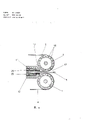
Fig. 6. the double belt press inlet region profile of tape entry end guide pulley, and
Fig. 7. the increased pressure board profilograph.
The double belt press 15 of the continuous operation of representing in Fig. 1 has four guide pulleys 1,2,3,4 that can be rotated to support on the support of bearing 5,6.What be centered around that per two guide pulleys outside detours is to add pressure zone 7,8.Direction of arrow rotation shown in per two guide pulleys are respectively pressed on guide pulley 1 and 4.Usually add pressure zone 7,8 by existing method by what high-tensile steel band was made, for example by being fixed on the hydraulic cylinder tensioning on the support of bearing 5,6.The last following reversion section that adds pressure zone 7 and add down pressure zone 8 on be so-called reaction zone 10 between the reversion section.In reaction zone, be in to add under the condition that gentleness adds surface pressure by the band material 9 that advances for right-to-left among the figure and be pressed.Band expects 9 by the fabric that flooded artificial resin, laminated material, and fiber binding agent composite material and other similar material are made.For instance, form by being stacked with the impregnated glass fabric band of polyimides from level to level by a kind of this class band material 9.
The surface pressure that is added in the reaction zone 10 on the band material 9 acts on the inner surface that adds pressure zone 7,8 reversion sections by increased pressure board 11,12 with the mode of hydraulic pressure, is delivered to band more therefrom and expects on 9.The reaction force that is produced by stampings passes to the forcing press support 13,14 that only schematically illustrates through increased pressure board 11,12 and gets on figure.The support of bearing 5,6 equally also is fixed on the forcing press support 13,14.
In order to produce the surface pressure that acts on the band material 9, under pressure, the flowing pressure medium poured into increased pressure board 11,12 and add in the chamber between pressure zone 7, the 8 reversion section inner surfaces and go.The chamber of this so-called compression chamber 16, the side is the boundary with the sealing device structure 17 of closed-loop shaped.Preferably adopt artificial oil to make pressure medium.But adopt gas for example compressed air also can reach effect same.
Represented among Fig. 2 that a this compression chamber 16 is from adding the vertical view that the pressure zone back side is seen.Rectangle increased pressure board 11 is made by a block plate.There is sealing device structure 17 marginal zone of increased pressure board 11, and it is made up of two that separate with an intermediate cavity 20 closed-loop shaped sealing device on slip face that adjoin 18 and 19 in the present embodiment.These sealing device on slip face 18,19 all are loaded in the groove 21 on increased pressure board 11.As represented by means of sealing device on slip face 18 among Fig. 3, sealing device on slip face 18 adds pressure zone 7 sliding-contacts with one surface with mobile sealing device on slip face 18 below.Sealing device on slip face 18 embeds in " U " shape fixing bar 22 away from the side that adds pressure zone with it, and the fixing bar leans against on the wall of groove 21, and the gap between them is very little.Adorned a groove sealing device 23 that is designed to round section joint ring of making by elastomeric material at " U " shape fixing bar 22 on away from that side that adds pressure zone 7.Acted on the pressure medium that comes from the bottom land of groove 21 above the groove sealing device 23 at this, institute is so that fixing bar 22 and by it sealing device on slip face 18 is pressed in to add on the pressure zone 7, thereby compression chamber 16 and atmospheric side 24 are isolated.The fixing means of " U " shape fixing bar 22 in increased pressure board 11 is existing, as sees from DE-PS2722197, so this be need not to elaborate here.As seen by means of Fig. 7 of back, collect the pressure medium that leaks out by compression chamber 16 in the intermediate cavity 20 between two sealing device on slip face 18 and 19, and can be by the there through via hole 45 and collecting pipe 46 sucking-offs.
Sealing device on slip face 18,19 is by a kind of plastics, and preferably a kind of elastomer is made.But the temperature maximum that this material can bear in long-term work can only arrive 250 ℃, represents this temperature with T1 below.Requirement has much higher temperature T 2 yet many band material 9 harden when compacting fully.For example need be up to 380 ℃ temperature for the laminated material of making by the glass fabric that flooded polyimide resin.In order to make double belt press also can be applicable to these instructions for uses, the inner region that will increased pressure board is divided into the marginal zone and separate with it by method of the present invention then.Inner region is made of the visible increased pressure board inserts 25 that is in 16 inside, compression chamber in Fig. 4, and the marginal zone is made of remaining increased pressure board 11,12.Increased pressure board inserts 25 is heated to a temperature T 3 higher than increased pressure board 11,12, and this temperature will equal T2 at least, but preferably will be higher than it.Increased pressure board 11,12 remains on the temperature, and it is up to T1.
Increased pressure board inserts 25 is as shown in Fig. 4 and Fig. 7.The rectangular channel 28 that a peviform is arranged on the increased pressure board 11,12, it is surrounded by the edge 26 of the projection of a sealing, and sealing device structure 17 is housed in edge 26.Increased pressure board inserts 25 in groove 28 is supported on the pressure medium 29 floatingly, so formed a gap 37 between increased pressure board 11,12 and increased pressure board inserts 25, has been full of pressure medium 29 in the gap 37.Increased pressure board inserts 25 is for bearing thrust, and is local by very little connector and increased pressure board 11,12 fixed connections of cross section at a few.This connector for example can be the screw 30 of band sleeve 31.Distance between increased pressure board 11,12 and the increased pressure board inserts 25 can keep very for a short time, for example about 1 millimeter.If but, also can select greatly again according to the needs of thermal insulation.
Increased pressure board inserts 25 has the groove 32 along the width horizontal expansion that indentation disposes at it on the surface that adds pressure zone, insert in the groove equally also to be zigzag serpentine heating pipe 33.Be with copper pipe 34 on the serpentine heating pipe 33, copper pipe is fixed on the wall of groove 32 with good heat conduction contact.Serpentine heating pipe 33 is by lead-in wire 35 supply electric energy.Lead-in wire 35 imports through a bellows 36 from the outside, and bellows 36 is tied increased pressure board 11,12 and increased pressure board inserts 25 with respect to the pressure medium in the gap 37 29 hermetically in a place.By means of serpentine heating pipe 33 metal increased pressure board inserts 25 is heated to temperature T 3, this temperature preferably is higher than the band material 9 necessary temperature T 2 of hardening fully.If desired, can also utilize deep fat heating increased pressure board inserts 25, deep fat is seen Fig. 5 through the turnover conduit in bellows 36 by the hole 52(that is located in the increased pressure board inserts 25) circulation.
Increased pressure board 11,12 itself is heated to temperature T 1, its most high maximum temperature that can bear in the material long-term work of sealing device on slip face 18,19, but preferably than much lower temperature.For this reason, in increased pressure board 11,12 processing porose 27, cross deep fat with temperature required T1 at their intermediate flows.Therefore think that also there is this temperature T 1 at the edge 26 of projection of increased pressure board 11,12, and be contained in sealing device on slip face on this protruding edge 26 also with bearing temperature T1.If necessary can also cool off increased pressure board 11,12, at this moment flow through cooling liquid in the hole 27 with selected proper temperature.Because separate with gap 37 between increased pressure board 11,12 and the increased pressure board inserts 25, and in the gap, fill with immobilising fluid pressure medium 29, almost any heat is passed to increased pressure board 11,12 so have the increased pressure board inserts 25 of the higher temperature T3 that sealing device on slip face 18,19 is harmful to.Well-known this fluid pressure medium has very poor thermal conductivity, and in fact it become an adiabatic apparatus.Therefore only by bellows, screw 30 etc. hot-fluid to increased pressure board 11,12 appears just now connected to one anotherly at those increased pressure boards 11,12 and increased pressure board inserts 25.But this amount is very little, because this jockey seldom, moreover their cross section is also all little.If necessary, these minimal heat flows can be taken away it by cooling increased pressure board 11,12, are no more than temperature T 1 so that guarantee the sealing device structure on the edge 26 of projection.
As among Fig. 6 by means of the section of an inlet region 47 by double belt press 1 represented, porose 49 in the arrival end guide pulley 1 and 4, they are positioned near guide pulley 1,4 outer surfaces.Deep fat circulates in hole 49, the outer surface of heating guide pulley, and that part that abuts on the guide pulley 1,4 in adding pressure zone 7,8 runnings by heat conduction heating simultaneously adds pressure zone 7,8.Should be controlled at when it leaves guide pulley 1,4 heating that adds pressure zone 7,8 and to be up to temperature T 1, this temperature is harmless for the material of sealing device on slip face 18,19.Add and continue to move after pressure zone 7,8 leaves guide pulley 1,4 to the direction of reaction zone 10, and the leading section 50 of the sealing device on slip face 17 of process in increased pressure board 11,12.The leading section of sealing device on slip face 18,19 refers to perpendicular to pressurization tape travel direction and extends and that part of 47 towards the inlet region along the width of increased pressure board 11,12.Because adding pressure zone 7,8 its maximum temperature through leading section 50 time is T1, so protected the sealing device on slip face 18,19 of leading section 50 can not be subjected to excessive heat effects.If do not wish to heat pressure zone 7,8, then can cancel the heating of this part, so add pressure zone 7,8 with room temperature process leading section by the guide pulley 1,4 of arrival end.Because temperature T 1 is still not high enough concerning the compacting of band material 9, so add pressure zone 7,8 through will be behind the leading sections 50 to they further heating.
Be heated to press belt material 9 needed temperature T 2 in order to add pressure zone 7,8, in increased pressure board inserts 25, adorned heat conducting element 38.As seen from Figure 4, these heat conducting elements 38 have circular cross-section, and they are contained in the hole of increased pressure board inserts 25, and with increased pressure board inserts 25 good thermo-contact are arranged.Heat conducting element 38 deviates from that surface of increased pressure board inserts 25 and adds pressure zone 7,8 sliding-contacts with it.Temperature is up to T1 when adding pressure zone 7,8 and entering reaction zone 10, so at the increased pressure board inserts 25 with temperature T 3 with add between the pressure zone 7,8 and caused thermograde.Add on the pressure zone 7,8 so the heat conducting element 38 that hot-fluid is made of such as copper via the material with thermal conductive resin from increased pressure board inserts 25 flows to, add pressure zone and in motion process, be heated by reaction zone 10 so that make.The temperature T 3 of the quantity of heat conducting element 38 and increased pressure board inserts 25 be chosen to can will add pressure zone be heated to the required higher temperature T2 of band material 9.As seen from Figure 2, heat conducting element 38 is arranged to make them will be in just that a part of heating tape 7,8 facing to increased pressure board inserts 25 is heated to higher temperature T 2 between two lateral parts 51 of slides within face seals 19, and do not heat contact with sealing device on slip face 18,19 add pressure zone both sides of the edge district.As can be seen from Figure 4, flooded the band material 9 of the glass fabric composition of polyimide resin in the present embodiment for multilayer, its width equals the width of increased pressure board inserts 25 at most, thus this band material just in time be in have higher temperature T2 in the reaction zone add pressure zone 7,8 parts.The structure of heat conducting element 38 is by known among the open file DE-OS3325578, so need not here to be described further.
Because be subjected to the heating of increased pressure board inserts and be in the inner region of temperature T 2 and have and exist thermograde between the marginal zone of temperature T 1 adding on the pressure zone 7,8 vertically (that is perpendicular to pressurization tape travel direction), making sealing device on slip face 18,19 bear too high thermic load so can form one hot-fluid along sealing device on slip face lateral parts 51.At this moment the lateral parts for sealing device structure 17 51 refers to along adding the part that pressure zone 7,8 directions of advance are extended.Get in order not make these heats pass to sealing device on slip face 18,19, can additionally cool off the marginal zone that adds pressure zone.
This cooling device that adds pressure zone 7,8 marginal zones is found in Fig. 4.On the edge 26 of increased pressure board 11,12 projectioies, be provided with the pressure fluid house steward 40 who extends along pressurization tape travel direction.Those holes 41 of setting spaced apart communicate with house steward 40 on the surface that adds pressure zone at the edge 26 of projection.Sealing device on slip face 19 was near that side of increased pressure board inserts 25 in these Kong Jun were in.At this moment some pressure medium 29 flows into house steward 40 by these holes 41, flows to the reservoir of pressure medium again from house steward, and pressure medium enters compression chamber 16 once more then.By such circulation, the pressure medium process has absorbed heat with the convection current that adds pressure zone 7,8 marginal zones, thereby has prevented from the marginal zone is heated to the degree that allows above sealing device on slip face.
If the such cooling in pressurization belt edge district not enough, can also heat conducting element be set in this marginal zone so.As seen from Figure 5, the heat conducting element 42 identical with structure in increased pressure board inserts 25 is installed on the edge 26 of increased pressure board 11,12 projectioies sealing device on slip face 19 near 37 those sides of gap.These heat conducting elements 42 on the one hand with the marginal zone in add pressure zone 7,8 sliding-contacts, contact with the edge 26 of projection on the other hand.Preferably can be lower because the temperature that increased pressure board has is up to T1(by cooling), thus flow to the edge 26 of projection by adding the next heat of pressure zone inner region through heat conducting element 42, and take away by the cooling liquid of increased pressure board 11,12 therefrom.Therefore guaranteed adding the pressure zone temperature and can not be increased to the temperature T 1 that can bear above sealing device on slip face 18,19 reliably in the marginal zone.
The rearward end 43 of sealing device structure 17 is meant to be in along adding pressure zone 7,8 direction of advance B among Fig. 2 and adds the part that pressure zone extends perpendicular to direction B edge in the sealing device structure 17 of increased pressure board inserts 25 back.Along with adding moving forward of pressure zone 7,8, this part with add pressure zone on have a higher temperature the zone contact, so must prevent the overheated of sealing device on slip face 18,19 there equally.For this reason, as shown in Figure 2, the heat conducting element 44 that contacts with increased pressure board 11,12 is set between end play 37 and the rearward end 43 in this zone.These heat conducting elements 44 with add the pressure zone sliding-contact, and heat led toward increased pressure board 11,12 from adding pressure zone, this is because in this area, be heated to temperature and be T2 add pressure zone and maximum temperature is to exist thermograde between T1 even the increased pressure board that also will hang down some again.The quantity of heat conducting element 44 is chosen as and makes that to add the material that reaches heavily again sealing device on slip face when in a single day pressure zone arrives the rearward end 43 of sealing device on slip face be harmless temperature T 1.If this cooling section is still not enough, so can be with increased pressure board 11,12 separated into two parts, the strong cooling of increased pressure board part that wherein has heat conducting element 44, and it is independent of another part increased pressure board with increased pressure board inserts 25, thereby the rearward end 43 that has guaranteed sealing device structure 17 can be owing to the too high and excess load of temperature yet.
In order to obtain to satisfy the finished product of quality requirement, when band material 9 advances by double belt press, must guarantee that selected increased pressure board inserts can make the band material harden fully along the length of pressurization tape travel direction and the speed of service that adds pressure zone 7,8 in the time of the reaction zone 10 that its size is determined by increased pressure board inserts 25.If the width of band material 9 is elected the width greater than increased pressure board inserts 25 as, the limit of down trodden band material 9 in the scope of the reaction zone 10 that adjoins at edge 26 so with projection, after leaving double belt press 15 outlet areas 48, to excise in band material 9, because this part does not have fully sclerosis fully owing to temperature is lower.
Claims (14)
1, double belt press with the continuous press belt material of higher temperature, stacked heatable non junction adds pressure zone it has two in frame about, adding pressure zone is tensioned on two rotatable guide pulleys separately, also has the compression chamber, this compression chamber be the boundary up and down by pressurization belt surface and increased pressure board, the side is the boundary by one adding the sealing device that slides on the pressure zone, act on by the flowing pressure medium in the compression chamber and to add the inboard surface pressure of pressure zone, this pressure is acted on the last band material that adds in capable next time section of pressure zone and the following reaction zone that adds between the pressure zone row last time section, it is characterized by: increased pressure board (11,12) have a marginal zone and one and this inner region that distinguishes, the marginal zone surrounds this inner region fully, and contain the sealing device structure (17) of compression chamber (16), in order to heat inner region, be provided with thermal source at inner region, at inner region with add pressure zone (7,8) against between inner region that part of, existing heat conducting element (38) is housed, their surface leans against on the inner region, another surface with add pressure zone (7,8) sliding-contact will be so that will add pressure zone (7,8) lean against that part of on the inner region and be heated to higher temperature.
2, according to the described double belt press of claim 1, it is characterized by, increased pressure board (11,12) has a rectangular channel (28), and it entirely is within the increased pressure board (11,12), the marginal zone is made of increased pressure board (11, the 12) part that with this rectangular channel (28) is the border, be provided with an increased pressure board inserts (25) that constitutes inner region in rectangular channel (28), it separates with increased pressure board (11,12) by gap (37).
3, according to the described double belt press of claim 1, it is characterized by: only the mechanical type retaining element by little cross section is fixed on the increased pressure board (11,12) increased pressure board inserts (25) in a few place.
4, according to the described double belt press of claim 3, it is characterized by: fixed mechanical component is made of screw (30) and the distance bush (31) in gap (37).
5, according to the described double belt press of claim 1, it is characterized by: heat insulation between inner region and the marginal zone by flow media.
6, according to the double belt press of claim 5, it is characterized by: this flow media is simultaneously as pressure medium.
7, according to the described double belt press of claim 1, it is characterized by: the input channel of thermal source passes increased pressure board (11,12) introducing in the increased pressure board inserts (25) in a bellows (36), and bellows is tied increased pressure board (11,12) and increased pressure board inserts (25) hermetically with respect to gap (37).
8, according to the described double belt press of claim 1, it is characterized by, thermal source is by constituting by electrically heated serpentine heating pipe (33).
9, according to the described double belt press of claim 8, it is characterized by: serpentine heating pipe (33) is contained in the groove (32) of increased pressure board inserts (25) circuitously.
10, according to the described equipment of claim 1, it is characterized by: thermal source is made of the hole (52) in the increased pressure board inserts (25), flows through a kind of heat-carrying agent in the hole.
11, according to the described equipment of one of claim 1 to 10, it is characterized by: sealing device structure (17) is positioned at increased pressure board (11,12) on Tu Qi edge (26), the scope that is in raised brim (26) is interior also along the sealing device on slip face (18 by the setting of pressurization tape running direction, 19) this part pressurization band (7 of lateral parts (51), 8) cool off by means of convection current by pressure medium (28), pressure medium is by being arranged near the interior sealing device on slip face (19) on the lateral parts (51), the hole of (16) one sides (41) are sucked away towards the compression chamber, these holes link to each other with the house steward who is arranged in raised brim (26) (40), and pressure medium is (41) through the hole, house steward (40) is sent in the pressure medium reservoir.
12, according to the described equipment of one of claim 1 to 10, it is characterized by: sealing device structure (17) is located at increased pressure board (11,12) on Tu Qi edge (26), and go up lateral parts (51) along the interior sealing device on slip face (19) that is provided with by pressurization tape running direction (16) beyond is equipped with heat conducting element (42) towards the compression chamber at this protruding edge (26), a surface of heat conducting element leans against on the edge (26) of projection, and with its another surface with add pressure zone (7,8) go up that a part of sliding-contact that faces toward sealing device structure lateral parts (51), so heat is led toward increased pressure board (11 from this part that adds pressure zone, 12).
13, according to the described equipment of one of claim 1 to 10, it is characterized by: sealing device structure (17) is located at increased pressure board (11,12) on Tu Qi edge (26), and along sealing device structure (17) rearward end (43), that is along with add pressure zone (7,8) direction of advance is vertical and from adding pressure zone (7,8) direction of advance is seen as the sealing device on slip face part that is contained in increased pressure board inserts (25) back, and add pressure zone (7 facing to this part of edge (26) in-scope of projection, 8) cool off by means of convection current by flowing pressure medium (29), the hole (41) of (16) one sides is sucked away pressure medium towards the compression chamber near the rearward end (43) by being located at, these holes link to each other with the house steward (40) at the edge (26) that is arranged in projection, pressure medium is (41) through the hole, house steward (40) is sent in the pressure medium reservoir, so when adding pressure zone (7, when 8) passing through the rearward end (43) of sealing device structure (17), the most high maximum temperature that can bear in the material of sealing device of the temperature that it had.
14, according to the described equipment of one of claim 1 to 10, it is characterized by: sealing device structure (17) is located at increased pressure board (11,12) on Tu Qi edge (26), edge (26) upper edge sealing device structure (17) rearward end (43) in projection, that is along with add pressure zone (7,8) direction of advance is vertical and from adding pressure zone (7,8) direction of advance is seen as the sealing device on slip face part that is contained in increased pressure board inserts (25) back, and beyond compression chamber (16), heat conducting element (44) is housed, its surface leans against on the edge (26) of projection, and with its another surface with add pressure zone (7,8) be in that a part of sliding-contact between sealing device structure rearward end (43) and the increased pressure board inserts (25) on, so heat is led toward increased pressure board (11 from this part that adds pressure zone, 12), when adding pressure zone through rearward end (43), the most high maximum temperature that can bear in the material of sealing device of the temperature that it had.
Applications Claiming Priority (2)
| Application Number | Priority Date | Filing Date | Title |
|---|---|---|---|
| DEP3534478.4 | 1985-09-27 | ||
| DE3534478A DE3534478C2 (en) | 1985-09-27 | 1985-09-27 | Double belt press for the continuous pressing of material webs at elevated temperatures |
Publications (2)
| Publication Number | Publication Date |
|---|---|
| CN86106003A CN86106003A (en) | 1987-04-15 |
| CN1003356B true CN1003356B (en) | 1989-02-22 |
Family
ID=6282109
Family Applications (1)
| Application Number | Title | Priority Date | Filing Date |
|---|---|---|---|
| CN86106003.2A Expired CN1003356B (en) | 1985-09-27 | 1986-09-06 | Method and equipment for continously making strip materials under high temp. |
Country Status (6)
| Country | Link |
|---|---|
| US (1) | US4723484A (en) |
| EP (1) | EP0216226B1 (en) |
| JP (1) | JPS6274611A (en) |
| CN (1) | CN1003356B (en) |
| DE (1) | DE3534478C2 (en) |
| SU (1) | SU1612988A3 (en) |
Families Citing this family (26)
| Publication number | Priority date | Publication date | Assignee | Title |
|---|---|---|---|---|
| USRE35091E (en) * | 1986-08-18 | 1995-11-21 | Mascheninfabrik Andritz Actiengesellschaft | Pressure device and seal for filter belt machines |
| AT385681B (en) * | 1986-08-18 | 1988-05-10 | Andritz Ag Maschf | PRINTING DEVICE FOR MACHINES OR PROVIDED MACHINE FOR DRAINING OR FILTER OR FOR PRESSED GOODS |
| DE3709958A1 (en) * | 1987-03-26 | 1988-10-13 | Santrade Ltd | Double-belt press |
| DE3717308A1 (en) * | 1987-05-22 | 1988-12-15 | Held Kurt | DOUBLE BELT PRESS FOR THE CONTINUOUS PRODUCTION OF ENDLESS MATERIALS |
| DE3719976A1 (en) * | 1987-06-15 | 1988-12-29 | Hymmen Theodor Gmbh | METHOD AND DEVICE FOR APPLYING A SURFACE PRESS TO WORKPIECE DRIVEN BY PRESSURE BELTS |
| DE3902255A1 (en) * | 1989-01-26 | 1990-08-02 | Nokia Unterhaltungselektronik | METHOD AND DEVICE FOR PRODUCING A LIQUID CRYSTAL CELL |
| FR2646579A1 (en) * | 1989-03-20 | 1990-11-02 | Guillemot Gerard | ELECTRICALLY HIGH TEMPERATURE HEATING EQUIPMENT BY REGULATED AREAS FOR THE USE OF COMPOSITE MATERIAL PRODUCTS |
| US5352321A (en) * | 1989-06-29 | 1994-10-04 | Kurt Held | Continuously operating double band press |
| US5183525A (en) * | 1990-05-24 | 1993-02-02 | United Container Machinery Group, Inc. | Heater for a double facing corrugating machine |
| EP0550782B1 (en) * | 1990-12-24 | 1995-10-18 | Kurt Held | Continuous double-band press |
| DE4128024A1 (en) * | 1991-08-23 | 1993-02-25 | Held Kurt | CONTINUOUSLY WORKING DOUBLE BAND PRESS |
| ATA185093A (en) * | 1993-09-14 | 2000-06-15 | Danubia Petrochem Polymere | DOUBLE BELT PRESS WITH HYDROSTATIC BELT SUPPORT |
| DE4335749A1 (en) * | 1993-10-20 | 1995-04-27 | Danubia Petrochem Deutschland | Double-belt press with hydrostatic belt support |
| DE4442320A1 (en) * | 1994-11-29 | 1996-05-30 | Danubia Petrochem Deutschland | Reinforced thermoplastic strip mfr. and mfg. plant |
| US5705026A (en) * | 1995-04-10 | 1998-01-06 | Latter; Melvin R. | Modular sealing machine |
| US5885411A (en) * | 1995-04-10 | 1999-03-23 | Latter; Melvin R. | Modular sealing machine |
| US6908295B2 (en) * | 2000-06-16 | 2005-06-21 | Avery Dennison Corporation | Process and apparatus for embossing precise microstructures and embossing tool for making same |
| DE102004060492A1 (en) * | 2004-12-16 | 2006-06-29 | Sig Technology Ag | Goods e.g. package materials, transporting device e.g. belt conveyor, has pressing unit with thrust bolts that are adjustably supported perpendicular to gap between contact sections and are loaded with forces effected in direction of gap |
| CN104129086B (en) * | 2014-07-08 | 2016-04-13 | 广东特固力士工业皮带有限公司 | The dull and stereotyped Plasticator of a kind of thermoplastic elastomer (TPE) conveyer belt |
| US10421305B2 (en) * | 2015-05-21 | 2019-09-24 | Chums, Inc. | Feed-through thermal pressing system and associated components |
| ITUB20160504A1 (en) | 2016-01-15 | 2017-07-15 | System Spa | FORMAT COMPENSATOR FOR A PRESSING DEVICE |
| DE102018215939A1 (en) * | 2018-09-19 | 2020-03-19 | Profol GmbH | Tool for applying a film |
| US20220260050A1 (en) * | 2019-07-16 | 2022-08-18 | General Electric Company | System and method for manufacturing panels for use in wind turbine rotor blade components |
| EP4045301A4 (en) * | 2019-10-18 | 2023-11-08 | Välinge Innovation AB | A continuous press arrangement for manufacture of building panels |
| CA3156064A1 (en) * | 2019-10-18 | 2021-04-22 | Valinge Innovation Ab | A continuous press arrangement for manufacture of building panels |
| JP7058852B1 (en) * | 2021-12-28 | 2022-04-25 | 株式会社Sgic | Double belt press |
Family Cites Families (12)
| Publication number | Priority date | Publication date | Assignee | Title |
|---|---|---|---|---|
| US2364597A (en) * | 1942-03-09 | 1944-12-12 | Penokee Veneer Company | Press |
| US3185073A (en) * | 1963-02-12 | 1965-05-25 | Hoover Ball & Bearing Co | Apparatus for preventing belt distortion |
| US3386503A (en) * | 1966-02-24 | 1968-06-04 | Continental Can Co | Differential heating plate |
| FI67509C (en) * | 1971-05-24 | 1985-04-10 | Into Kerttula | KONTINUERLIGT ARBETANDE SKIVPRESS |
| DE2248810A1 (en) * | 1972-10-05 | 1974-04-11 | Wagener & Co | Conveyor belt joining press - using rubber or similar base plate clamped to an inflatable cushion |
| DE2722197C2 (en) * | 1977-05-17 | 1979-06-07 | Kurt 7218 Trossingen Held | Sliding surface seal on continuous laminating machines |
| DE3046431A1 (en) * | 1980-12-10 | 1982-09-09 | Santrade Ltd., 6002 Luzern | Double band press with pneumatic support - has circumferential cooling on heating medium channels near seals |
| DE3135031C2 (en) * | 1981-09-04 | 1983-07-21 | Held, Kurt, 7218 Trossingen | Double belt press for applying surface pressure |
| EP0087651B2 (en) * | 1982-02-27 | 1994-06-08 | Kurt Held | Apparatus to support pressure bands in a roll-supported double band press |
| JPS5933312A (en) * | 1982-08-16 | 1984-02-23 | Mitsubishi Chem Ind Ltd | Polymerization of n-vinylcarboxamide |
| DE3348485C2 (en) * | 1983-07-15 | 1995-06-08 | Held Kurt | Double belt press for the continuous production of laminates |
| DE3416985A1 (en) * | 1984-05-08 | 1985-11-14 | Held, Kurt, 7218 Trossingen | METHOD AND DEVICE FOR CONTINUOUSLY PRESSING MATERIAL RAILS |
-
1985
- 1985-09-27 DE DE3534478A patent/DE3534478C2/en not_active Expired - Fee Related
-
1986
- 1986-09-05 EP EP86112280A patent/EP0216226B1/en not_active Expired - Lifetime
- 1986-09-06 CN CN86106003.2A patent/CN1003356B/en not_active Expired
- 1986-09-16 SU SU864028119A patent/SU1612988A3/en active
- 1986-09-26 US US06/912,587 patent/US4723484A/en not_active Expired - Fee Related
- 1986-09-26 JP JP61226348A patent/JPS6274611A/en active Granted
Also Published As
| Publication number | Publication date |
|---|---|
| DE3534478C2 (en) | 1995-01-26 |
| EP0216226B1 (en) | 1990-07-04 |
| CN86106003A (en) | 1987-04-15 |
| JPS6274611A (en) | 1987-04-06 |
| SU1612988A3 (en) | 1990-12-07 |
| EP0216226A3 (en) | 1988-12-28 |
| DE3534478A1 (en) | 1987-04-02 |
| JPH0339811B2 (en) | 1991-06-17 |
| US4723484A (en) | 1988-02-09 |
| EP0216226A2 (en) | 1987-04-01 |
Similar Documents
| Publication | Publication Date | Title |
|---|---|---|
| CN1003356B (en) | Method and equipment for continously making strip materials under high temp. | |
| JPH0357593A (en) | Double belt press | |
| JPH0445279B2 (en) | ||
| US5558016A (en) | Arrangement for applying a surface pressure to workpieces driven by a pressing band | |
| FI96790B (en) | Device for drying and smoothing the fibrous web | |
| GB2199398A (en) | Dewatering a web of fibrous material | |
| FI70541B (en) | ANORDNING FOER FOERENING AV FLERE ARBETSMATERIALSKIKT | |
| US4887362A (en) | Method and an apparatus for drying a paper web or the like | |
| US5352321A (en) | Continuously operating double band press | |
| CN1015296B (en) | Two -belts press with heating or coding parts and method for manufacturing the parts | |
| JP4735367B2 (en) | Injection molding equipment | |
| US5272967A (en) | Continuously operating double band press and heat conducting element therefor | |
| FI56334C (en) | KONTINUERLIGT ARBETANDE PLANPRESS | |
| US3856674A (en) | Filtering process and apparatus | |
| IE781131L (en) | Heat treatment of fibrous material. | |
| US4693859A (en) | Method for continuous heated pressing of material in sheet form | |
| AU1810402A (en) | Rotary-die-method and fill wedge for producing capsules, in particular soft capsules | |
| EP1304201A1 (en) | Plant for preheating porous thermoformable material and pressing method | |
| CA2315822A1 (en) | Heating system for compressive shrinkage machines | |
| US5933978A (en) | Method of and apparatus for drying a fiber web | |
| RU2016761C1 (en) | Double-action auger extruder | |
| CN219741920U (en) | Temperature adjusting device and temperature adjusting garment | |
| ATE19799T1 (en) | HOT TROUBLES, ESPECIALLY MULTIPLE TROUBLES. | |
| GB2116305A (en) | Heat exchanger | |
| JPS56107508A (en) | Cooling device for forced circulating type oil-filled electric apparatus |
Legal Events
| Date | Code | Title | Description |
|---|---|---|---|
| C06 | Publication | ||
| PB01 | Publication | ||
| C10 | Entry into substantive examination | ||
| SE01 | Entry into force of request for substantive examination | ||
| C13 | Decision | ||
| GR02 | Examined patent application | ||
| C14 | Grant of patent or utility model | ||
| GR01 | Patent grant | ||
| C19 | Lapse of patent right due to non-payment of the annual fee | ||
| CF01 | Termination of patent right due to non-payment of annual fee |