CN100335309C - Outside rear-view mirror for vehicle - Google Patents
Outside rear-view mirror for vehicle Download PDFInfo
- Publication number
- CN100335309C CN100335309C CNB2004100004600A CN200410000460A CN100335309C CN 100335309 C CN100335309 C CN 100335309C CN B2004100004600 A CNB2004100004600 A CN B2004100004600A CN 200410000460 A CN200410000460 A CN 200410000460A CN 100335309 C CN100335309 C CN 100335309C
- Authority
- CN
- China
- Prior art keywords
- vehicle
- mentioned
- visible light
- view mirror
- outside rear
- Prior art date
- Legal status (The legal status is an assumption and is not a legal conclusion. Google has not performed a legal analysis and makes no representation as to the accuracy of the status listed.)
- Expired - Fee Related
Links
Images


Classifications
-
- B—PERFORMING OPERATIONS; TRANSPORTING
- B60—VEHICLES IN GENERAL
- B60R—VEHICLES, VEHICLE FITTINGS, OR VEHICLE PARTS, NOT OTHERWISE PROVIDED FOR
- B60R1/00—Optical viewing arrangements; Real-time viewing arrangements for drivers or passengers using optical image capturing systems, e.g. cameras or video systems specially adapted for use in or on vehicles
- B60R1/12—Mirror assemblies combined with other articles, e.g. clocks
- B60R1/1207—Mirror assemblies combined with other articles, e.g. clocks with lamps; with turn indicators
-
- B—PERFORMING OPERATIONS; TRANSPORTING
- B60—VEHICLES IN GENERAL
- B60R—VEHICLES, VEHICLE FITTINGS, OR VEHICLE PARTS, NOT OTHERWISE PROVIDED FOR
- B60R1/00—Optical viewing arrangements; Real-time viewing arrangements for drivers or passengers using optical image capturing systems, e.g. cameras or video systems specially adapted for use in or on vehicles
- B60R1/12—Mirror assemblies combined with other articles, e.g. clocks
- B60R2001/1253—Mirror assemblies combined with other articles, e.g. clocks with cameras, video cameras or video screens
Landscapes
- Engineering & Computer Science (AREA)
- Multimedia (AREA)
- Mechanical Engineering (AREA)
- Lighting Device Outwards From Vehicle And Optical Signal (AREA)
- Rear-View Mirror Devices That Are Mounted On The Exterior Of The Vehicle (AREA)
Abstract
An outside mirror (100, 100A, 100B) for a vehicle includes an image capturing unit (3) and a visible-light emitting unit (4, 4A) that emits visible light. Relative positional relation between the image capturing unit (3) and the visible-light emitting unit (4, 4A) is such that the visible light does not directly enter into the image capturing unit (3).
Description
Technical field
The present invention relates to possess the outside rear-view mirror for vehicle of camera head.In addition, the invention still further relates to the exterior mirror for vehicle lens device that possesses camera head and infrared radiation mechanism.
Background technology
As the outside rear-view mirror for vehicle that possesses camera head, the back mirror on Japanese publication english abstract (spy opens 2000-062531) for example on the books.In addition, as the outside rear-view mirror for vehicle that possesses camera head and infrared radiation mechanism, for example publication number is the US Patent of US2002/0118282A1, and it discloses a kind of back mirror, and wherein bulb 31 (bulb) only is to be used for the photography zone of pick up camera is illuminated.The image that both utilize camera head to take owing to can discern vehicle front-wheel and near periphery (axletree or ground plane of vehicle front-wheel) thereof, can be eliminated the dead angle of the sight line of vehicle front-wheel and periphery thereof.
But the both does not do any consideration to radiation of visible light mechanism this point is set.Therefore, both just are provided with radiation of visible light mechanism simply, then have the situation that is directly incident on camera head from the visible light of radiation of visible light mechanism irradiation.In this case, the image of being taken by camera head can produce blooming (perhaps halation), diminishes recognition effect.So,, can consider on camera head, to be provided with optional features such as light filter in order to solve the shortcoming part of recognition effect.But in this case, it is the major cause that causes the low and component costs rising of the performance of bottom line illumination etc. of reference object etc.Like this, there is above-mentioned problem in the both.
Publication number is that the US Patent of US2002/0071676A1 also discloses a kind of back mirror, and wherein lighting unit 20 and steering indicating light interlock only illuminate the photography zone of pick up camera.
Summary of the invention
The invention provides a kind of outside rear-view mirror for vehicle that can address the above problem.
To achieve these goals, the present invention is a kind of outside rear-view mirror for vehicle that possesses camera head, it is characterized in that: the radiation of visible light mechanism that is provided with the irradiation visible light, the relative position relation of above-mentioned camera head and above-mentioned radiation of visible light mechanism has from the visible light of above-mentioned radiation of visible light mechanism irradiation, be not directly incident on the relative position relation of above-mentioned camera head, above-mentioned radiation of visible light mechanism is the side turn signal that can replace being installed on the vehicle, the side Warning light, the illumination equipment of the steering indicating light of front combination lamp
Being provided with in above-mentioned radiation of visible light mechanism can be with the visible light distribution controls mechanism of visible light distribution controls in the scope of regulation,
Be provided with from the lens of the permeable transmitance of visible light of above-mentioned radiation of visible light mechanism irradiation, when outside rear-view mirror for vehicle is installed on the vehicle, above-mentioned visible light towards car body the place ahead roughly towards horizontal direction, the object lens of above-mentioned camera head towards the car body front lower place to.
Description of drawings
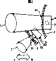
Fig. 1 is the External view of the embodiment 1 of expression outside rear-view mirror for vehicle of the present invention.
Fig. 2 is that expression lumps together a part of cross sectional drawing of the IIA-IIA line of Fig. 1 and a part of cross sectional drawing of IIB-IIB line, and the instruction diagram of relative position relation of the light source of the object lens of camera head and radiation of visible light mechanism is described.
Fig. 3 is the cross sectional drawing of the III-III line of Fig. 1, is the instruction diagram of relative position relation of the light source of expression object lens of camera head and radiation of visible light mechanism.
Fig. 4 is the External view of the embodiment 2 of expression outside rear-view mirror for vehicle of the present invention.
Fig. 5 is that expression lumps together a part of cross sectional drawing of the VA-VA line of Fig. 4 and a part of cross sectional drawing of VB-VB line, and the instruction diagram of relative position relation of the light source of the object lens of camera head and radiation of visible light mechanism is described.
Fig. 6 is the cross sectional drawing of the VI-VI line of Fig. 4, is the instruction diagram of relative position relation of the light source of expression object lens of camera head and radiation of visible light mechanism.
Fig. 7 is a part of cutting the fixed parts of the illumination equipment that is made of infrared radiation mechanism and radiation of visible light mechanism open, the block diagram of representing the part of the LED that flexible substrate and infrared light emission are used.
Fig. 8 be the VIII of Fig. 7 to view, be the back view of a part of the LED of expression flexible substrate and visible light illuminating.
Fig. 9 be the IX of Fig. 8 to view, be the birds-eye view of the part of expression flexible substrate and the LED of visible light illuminating and the LED that infrared light emission is used.
Figure 10 is the cross sectional drawing of the pith of expression embodiment 2 modified examples.
The specific embodiment
Two embodiment to outside rear-view mirror for vehicle of the present invention describe with reference to the accompanying drawings.Also have, the present invention is not subjected to the qualification of these embodiment.In addition, in the inscape of present embodiment, comprise so-called that can replace at an easy rate by those of ordinary skill in the art or be actually identical key element.
Also have, in this manual, the left side of so-called vehicle (automobile) is meant from the left side of seen the place ahead of driver one side (working direction of vehicle) situation.In addition, the right side of so-called vehicle is meant from the right side of the seen the place ahead situation of driver one side, have, so-called vehicle body the place ahead one side is meant seen the place ahead one side from driver one side again, also has so-called vehicle body rear one side to be meant seen rear one side from driver one side.
Fig. 1~Fig. 3 is the embodiment 1 of expression outside rear-view mirror for vehicle of the present invention.As shown in Figure 1, the outside rear-view mirror for vehicle 100 of this embodiment is the peepholes that are equipped in the left side of vehicle, and it possesses peephole base 1 and peephole shell 2.The back side of this peephole shell 2 is one side F towards vehicle body the place ahead.
Be separately installed with camera head 3 in the bottom at above-mentioned peephole shell 2 back sides and as the side turn signal 4 of radiation of visible light mechanism.The yellow visible light of above-mentioned side turn signal 4 irradiations.The relative position relation of this camera head 3 and side turn signal 4, as described below, the visible light with steering indicating light 4 irradiations from the side is not directly incident on the relative position relation of camera head 3.
That is, as Fig. 1~shown in Figure 3, above-mentioned camera head 3 is installed in vehicle body the place ahead one side F with respect to above-mentioned side turn signal 4 and near peephole base 1 one sides (near vehicle body one side).On the other hand, same as Fig. 1~shown in Figure 3, above-mentioned side turn signal 4 is installed in vehicle body rear one side B with respect to above-mentioned camera head 3, and with the opposite side (is the outside with respect to vehicle body) of close peephole base 1 one sides.In addition, above-mentioned side turn signal 4 be arranged on the longitudinally of above-mentioned peephole shell 2 (from above-mentioned peephole base 1 one sides to the direction of peephole base 1 an opposite side).
In addition, be respectively arranged with the lens 41 that the transmittance of the camera window 31 of shooting usefulness of camera head 3 and side turn signal 4 is used at the back side of above-mentioned peephole shell 2.Above-mentioned camera window 31 is provided with a little on the lower side.On the other hand, said lens 41 roughly is arranged to horizontal direction and the one side F towards vehicle body the place ahead.In addition, said lens 41 is made of the material that sees through from the transmitance of the visible light of above-mentioned side turn signal 4 irradiations.This side turn signal 4 is covered by said lens 41.
Above-mentioned camera head 3 is ccd video cameras for example, and it possesses main body 32 and object lens 33.These object lens 33 are relative with above-mentioned camera window 31.This camera head 3 is taken by the situation of the image pickup scope C of 31 pairs of vehicle body the place aheads of camera window, one side F and downside.This image pickup scope C is when being equipped with peephole in the left side of vehicle, for the axletree of the near front wheel or near near the ground; Perhaps/and, when peephole being housed, for the axletree of off front wheel or near near the ground on the right side of vehicle.The information of being taken by this camera system 3 is being configured on the read out instrument on the driver's seat of vehicle (for example, but liquid crystal visual organ) as image information display.Like this, just can eliminate the axletree of vehicle front-wheel or near near the visual dead angles the ground.In addition, above-mentioned camera head 3 also can be mounted to respect to above-mentioned peephole shell 2 and can fascinate.This occasion can make camera head 3 fascinate by manual or remote control, thereby can adjust and control shooting direction and the camera angle of above-mentioned image pickup scope C.
In the inside of above-mentioned side turn signal 4, one or light sources 5 such as several LED or natural daylight electric light for example are installed.The light source 5 of this side turn signal 4 is relative with the lens 41 of above-mentioned peephole shell 2.This side turn signal 4 is provided with visible light control mechanism (not shown), and it makes from the light of light source 5 (yellow visible light) scioptics 41 irradiations (distribution controls) penetrate range L to the illumination of vehicle body the place ahead one side F.In addition, this side turn signal 4 is made of the fixed mechanism and the above-mentioned visible light control mechanism of above-mentioned light source 5 and fixing above-mentioned light source 5, becomes the modularity structure.Range L is penetrated in the illumination that this side turn signal 4 makes the light scioptics 41 from light source 5 shine vehicle front one side F, can bring into play the function of signal for turn.Utilize this side turn signal 4, can omit the side turn signal (side direction signal lamp) or the side Warning light of the right and left that is installed in the vehicle mudwing and/or be installed in the steering indicating light of front combination lamp of the left and right sides of front part of vehicle.
Exterior mirror for vehicle 100 in the present embodiment 1 has above such structure, below describes with regard to its action effect.
At first, take the information of image pickup scope C and be presented on the read out instrument, can eliminate the axletree of vehicle front-wheel or near near the visual dead angles the ground by camera head 3.On the other hand, because the range L irradiation of glimmering is penetrated in 4 pairs of illumination of side turn signal, can bring into play the function of turn sign.
At this moment, the light of the relative position relation that is installed in camera head 3 on the peephole shell 2 and side turn signal 4 respectively with steering indicating light 4 irradiations from the side is not directly incident on the relative position relation of camera head 3.That is, camera head 3 is installed in vehicle body the place ahead one side F with respect to side turn signal 4, and on the other hand, side turn signal 4 is installed in vehicle body rear one side B with respect to camera head 3.In addition, the object lens 33 of camera head 3 are relative with the camera window 31 that is provided with a little on the lower side.On the other hand, the light source 5 of side turn signal 4 and along continuous straight runs roughly and one side F is provided with towards vehicle body the place ahead lens 41 are relative.
Its result, the light of the light source 5 of steering indicating light 4 irradiation from the side is the direct object lens 33 of incident camera head 3 not.In addition, as shown in Figure 3, part or all overlaps even range L is penetrated in the illumination of the image pickup scope C of camera head 33 and side turn signal 4, and the light of steering indicating light 4 irradiations from the side can not be directly incident on camera head 3 yet.
Therefore, the image blurring phenomenon with image mechanism 3 shootings can not take place in the outside rear-view mirror for vehicle 100 of present embodiment 1, can obtain clear and definite recognition effect.In addition, also not do not reduce and the rising of component costs because of the performance of the bottom line illumination of the body that is taken that optional features such as light filter caused etc.And the outside rear-view mirror for vehicle 100 of present embodiment 1 utilizes side turn signal 4, can omit the steering indicating light of side turn signal or side Warning light and front combination lamp.Like this, the outside rear-view mirror for vehicle 100 of present embodiment 1 can prevent that the light that will be installed in the above-mentioned light irradiation on the vehicle is directly incident on camera head 3.
In addition, the outside rear-view mirror for vehicle 100 of present embodiment 1, because side turn signal 4 has the visible light control mechanism, so, can utilize the visible light control mechanism to carry out distribution controls in the scope E to penetrating in the illumination of regulation from the visible light of light source 5.Have, the outside rear-view mirror for vehicle 100 of present embodiment 1 is because side turn signal 4 is for the modularity structure, so various outside rear-view mirror for vehicle can be general again.And the outside rear-view mirror for vehicle 100 of this embodiment 1 because lens 41 cover side turn signal 4, enters side turn signal 4 so can prevent dust and silt.
In addition, the outside rear-view mirror for vehicle 100 of present embodiment 1 is owing to camera head 3 can fascinate by manual or remote control, so can adjust image pickup scope C.Also have,, also must adjust so that it is not directly incident on the object lens 33 of camera head 3 by the light of light source 5 irradiations of side turn signal 4 even in the occasion of adjusting image pickup scope C.
Fig. 4~Fig. 9 represents the embodiment 2 of outside rear-view mirror for vehicle of the present invention.Among the figure, the parts that the symbolic representation identical with Fig. 1~Fig. 3 is identical.The outside rear-view mirror for vehicle 100A of present embodiment 2, basic identical with the outside rear-view mirror for vehicle 100 of the above embodiments 1, as shown in Figure 4, be mounted in the peephole in the left side of vehicle, possess peephole base 1 and peephole shell 2.The back side of this peephole shell 2 is one side F towards vehicle body the place ahead.
Be separately installed with camera head 3, side turn signal 4A as radiation of visible light mechanism, the infrared radiation mechanism 6 identical in the lower backside of above-mentioned shell 2 with the camera head 3 of the foregoing description 1.Above-mentioned camera head 3 can be mounted to and can fascinate by above-mentioned relatively peephole shell 2.This occasion can make camera head 3 fascinate by manual or remote manipulation, can adjust and control shooting direction and the camera angle of above-mentioned image pickup scope C.Above-mentioned side turn signal 4A and above-mentioned infrared radiation mechanism 6 constitute illumination equipments.The yellow visible light of above-mentioned side turn signal 4A irradiation.The relative position relation of the side turn signal 4A of this camera head 3 and illumination equipment, as described below, the visible light with the irradiation of steering indicating light 4A from the side is the direct relative position relation of incident camera head 3 not.
That is, above-mentioned camera head 3 is as Fig. 4~shown in Figure 6, is installed in vehicle body the place ahead one side F and near peephole base 1 one sides (near vehicle body one side) with respect to the side turn signal 4A of above-mentioned illumination equipment.On the other hand, same as Fig. 4~shown in Figure 6, the side turn signal 4A of above-mentioned illumination equipment is installed in vehicle body rear one side B with respect to above-mentioned camera head 3, and an opposite side (is the outside with respect to vehicle body) of close and peephole base 1 one sides.In addition, on the side turn signal 4A of above-mentioned illumination equipment and the infrared longitudinally that is arranged on above-mentioned peephole shell 2 as irradiation means 6 (from above-mentioned peephole base 1 one sides to the direction of peephole base 1 an opposite side).
Light source as above-mentioned infrared radiation mechanism 6 is made of the LED60 that sends out infrared light.On the other hand, the light source as above-mentioned side turn signal 4A is that the LED40 that sends out visible light constitutes.The LED40 of visible light illuminating uses by the wavelength characteristic of the side turn signal rules defined LED as near yellow the 590nm or dark-brown scope.In addition, the LED60 that uses of infrared light emission uses and has the LED of wavelength characteristic as near the so-called rubescent outer linear light the 950nm.
The LED60 that above-mentioned several infrared light emissions are used is installed in the surface of a face of aforesaid substrate 7.The LED40 of above-mentioned visible light illuminating is installed in the surface of the another side of aforesaid substrate 7.That is the shared same substrate 7 of LED60 used of the LED40 of visible light illuminating and infrared light emission.Aforesaid substrate 7 is made of flexible substrate.Above-mentioned LED40,60 installations on the surface are the chips of LED in the surface of flexible substrate 7 and back side welding, cover chip with lens, these lens are fixed on the surface of flexible substrate 7 to form.Above-mentioned flexible substrate 7 is fixing by fixed parts 8.
Said fixing parts 8 as Fig. 5 and shown in Figure 7, are made of synthetic resin or glass, are the upper surface 81 with side 80 openings and the chevron shape of lower surface 82.Above-mentioned flexible substrate 7 is fixed on the lateral opening portion edge of this fixed parts 8.The installation of this flexible substrate 7 makes LED60 that infrared light emission the uses inside towards fixed parts 8.The configuration of this fixed parts 8 make the summit that forms by upper surface 81 and lower surface 82 towards vehicle body the place ahead one side F.
Above-mentioned side turn signal 4 is provided with visible light distribution controls mechanism 42.In this example, this visible light distribution controls mechanism 42 is made of parasite.This parasite 42 is arranged on the LED40 of the above-mentioned visible light illuminating of ratio on the peephole shell 2 more by rear one side (vehicle body rear one side B), and relative with the LED40 of above-mentioned visible light illuminating.42 pairs of light that sent by the LED40 of visible light illuminating of this parasite carry out distribution controls and with the visible light luminous intensity distribution range L 1 of its reflected illumination to vehicle body the place ahead F.Also have, parasite 42 directly forms control curved surface on shell 2, applies by direct evaporation, plating or high reflection and forms reflecting surface, also can be configured in the inside of the side turn signal 4 that is formed by metal parts.
Above-mentioned side turn signal 4 makes from the visible light reflection of the LED40 of visible light illuminating by parasite 42 and carries out distribution controls and penetrate range L 1 with the illumination that shines vehicle body the place ahead one side F.As a result, the relative position relation of this side turn signal 4 and above-mentioned camera head 3 has the relative position relation that is not directly incident on the object lens 33 of camera head 3 by the light of side turn signal 4 irradiations.In addition, this side turn signal 4 can be brought into play the function of signal for turn.Therefore, can omit the side turn signal (Warning light) of the right and left of the mudwing that is installed in automobile and be installed in the steering indicating light of front combination lamp of the left and right sides of the front portion of automobile.
Above-mentioned infrared radiation mechanism 6 is provided with infrared ray distribution controls mechanism 62.In this example, this infrared ray distribution controls mechanism 62 is made of the prism of following 82 the inboard that is arranged on said fixing parts 8.This prism 62 carries out distribution controls makes infrared radiation that the LED60 that used by infrared light emission sends to image pickup scope C (downside in vehicle body the place ahead) the essentially identical scope of camera head 3 or than the range L 2 of the also big circle of image pickup scope C.In addition, top 81 of fixed parts 8 both can make the infrared ray former state of the LED60 that uses from infrared light emission see through, and it is ended.
Above-mentioned infrared radiation mechanism 6 usefulness prisms 62 make the infrared ray refraction of the LED60 that uses from infrared light emission and it are carried out distribution controls, make the essentially identical scope of image pickup scope C of its irradiation and camera head 3 or than the range L 2 of the also big circle of image pickup scope C.Utilize above-mentioned prism 62, even the optical axis of the LED60 that uses at camera head 3 and infrared light emission is not simultaneously, also can be with the infrared ray distribution controls of the LED60 that uses from infrared light emission image pickup scope C at camera head 3, that is, and the range L 2 of regulation.
Above-mentioned side turn signal 4 and above-mentioned infrared radiation mechanism 6 constitute illumination equipments.This illumination equipment becomes the modularity structure.
The automobile of present embodiment 2 has as above structure with outside rear-view mirror 100A, below, its action effect is described.At first, make the LED60 that uses from infrared light emission send infrared light in the time of with the operation of the switch (not shown) in car camera head 3.So the infrared light of the LED60 that uses from infrared light emission sees through prism 62 and shines with image pickup scope C (downside in vehicle body the place ahead) essentially identical scope or than the range L 2 of the also big circle of image pickup scope C.As a result, because monitor etc. demonstrates image below the one side F of vehicle body the place ahead in car, so can eliminate the axletree of vehicle front-wheel or near near the visual dead angle the ground.In addition, the occasion that waits by day, it is not luminous can to operate the LED60 that camera head 3 uses infrared light emission yet.
In addition, make side turn signal 4 flickers luminous with the switch in the car.So, to reflect on parasite 42 from the visible light of the LED40 of visible light illuminating, flicker is radiated in the visible light luminous intensity distribution range L 1 of vehicle body the place ahead one side F.From the visible light of the LED40 of this visible light illuminating owing to be dark-brown, so play a role as side turn signal 4.
Like this, the automobile of present embodiment 2 outside rear-view mirror 100A, the same with outside rear-view mirror 100 with the automobile of the foregoing description 1, the information by camera head 3 shooting image pickup scope C also is presented on the read out instrument, just can eliminate the axletree or the subaerial visual dead angle of vehicle front-wheel.On the other hand, because shining illumination, side turn signal 4A flicker penetrates range L 1, so can bring into play the effect of turn sign.
At this moment, the light of the relative position relation that is installed in camera head 3 on the peephole shell 2 and side turn signal 4A respectively with steering indicating light 4A irradiation from the side is not directly incident on the relative position relation of camera head 3.That is, camera head 3 is installed in vehicle body the place ahead one side F with respect to side turn signal 4A, and on the other hand, side turn signal 4A is installed in vehicle body rear one side B with respect to camera head 3.In addition, the object lens 33 of camera head 3 a little on the lower side.On the other hand, by the visible light of side turn signal 4A irradiation towards vehicle body the place ahead one side F.
As a result, can not be directly incident on the object lens 33 of camera head 3 by the light of the LED40 irradiation of the visible light illuminating of side turn signal 4A.In addition, as shown in Figure 6, even part or all coincidence of range L 1 is penetrated in the illumination of the image pickup scope C of camera head 3 and side turn signal 4A, the light of steering indicating light 4 irradiations from the side can not be directly incident on camera head 3 yet.
Therefore, the image blurring phenomenon with image mechanism 3 shootings can not take place in the outside rear-view mirror for vehicle 100A of present embodiment 2, can obtain clear and definite recognition effect.In addition, can the performance of bottom line illumination etc. of body reduce and the rising of component costs because of optional features such as light filter cause being taken yet.And the outside rear-view mirror for vehicle 100A of present embodiment 2 utilizes side turn signal 4A, can omit the steering indicating light of side turn signal or side Warning light and front combination lamp.Like this, the outside rear-view mirror for vehicle 100A of present embodiment 2 can prevent to be directly incident on camera head 3 by the light that is installed in the above-mentioned light irradiation on the vehicle.
In addition, the outside rear-view mirror for vehicle 100A of this embodiment 2, owing on side turn signal 4A, have parasite 42 as visible light distribution controls mechanism, so, utilize parasite 42 to carry out distribution controls with penetrating range L 1 in the illumination of regulation from the visible light of the LED40 of visible light illuminating.
In addition, the outside rear-view mirror for vehicle 100A of present embodiment 2, owing in infrared radiation mechanism 6, be provided as the prism 62 of infrared ray distribution controls mechanism, utilize prism 62 infrared ray of the LED60 that uses from infrared light emission can be carried out distribution controls in the infrared ray range of exposures L2 of regulation.This infrared ray luminous intensity distribution range L 2 has and the essentially identical scope of image pickup scope C of camera head 3 or the scope of enclosing than image pickup scope C also big.In addition, if the infrared radiation of the LED60 that uses from infrared light emission to the image pickup scope C of camera head 3, then not necessarily is provided as the parasite 62 of this infrared ray luminous intensity distribution irradiation means.
In addition, the outside rear-view mirror for vehicle 100A of present embodiment 2, owing to be provided with the ultrared infrared transmitting lens that can see through the LED60 that uses from infrared light emission, promptly, fixed parts 8 enters the LED60 that infrared light emission is used so can prevent dust and silt.
In addition, the outside rear-view mirror for vehicle 100A of present embodiment 2 is because the illumination equipment that constitutes with side turn signal 4A and infrared radiation mechanism 6 is the modularity structure, so can be common to various outside rear-view mirror for vehicle.
In addition, the outside rear-view mirror for vehicle 100A of present embodiment 2 is owing to camera head 3 can fascinate by manual or remote manipulation, so can adjust image pickup scope C.Also have,, also need to adjust visible light by the LED40 irradiation of the visible light illuminating of side turn signal 4A so that it is not directly incident on the object lens 33 of camera head 3 even in the occasion of adjusting image pickup scope C.
In addition, the outside rear-view mirror for vehicle 100A of present embodiment 2, the light source of its infrared radiation mechanism 6 is made of the LED60 that sends infrared light, and the light source of its side turn signal 4A is made of the LED40 that sends visible light.Therefore, the outside rear-view mirror for vehicle 100A of present embodiment 2 compares with the device that uses filament lamp or infrared lamp, can miniaturization and energy-conservationization.
In addition, the outside rear-view mirror for vehicle 100A of present embodiment 2 is installed in the surface and the back side of substrate 7 owing to send out the LED40 of visible light with the LED60 that sends out infrared light, so the space that is provided with of light source is dwindled significantly.
In addition, the outside rear-view mirror for vehicle 100A of present embodiment 2, because the LED40 of visible light illuminating and two kinds of lighting means of LED60 that infrared light emission is used can common substrates 7, electric wiring, and fixed parts 8, so can correspondingly reduce component number, cost-cutting expense.
In addition, the outside rear-view mirror for vehicle 100A of present embodiment 2, because LED40,60 is installed in the surface of substrate 7, so, the height that is used for the light source (LED40) of visible light lighting means and the light source that is used for infrared light emission mechanism (LED60) with the lead of LED is compared with the lighting means that wicking is welded on the substrate, can reduce significantly, thus the degree of freedom of the layout of raising exterior mirror for vehicle.
In addition, the outside rear-view mirror for vehicle 100A of present embodiment 2 is made of flexible substrate because LED40,60 substrate 7 are installed, and therefore light source can, can improve source layout's design-calculated degree of freedom along with the design curved surface configuration of peephole shell 2 grades.
Figure 10 represents the modified example of the embodiment 2 of outside rear-view mirror for vehicle of the present invention.Among the figure, the parts that the symbolic representation identical with Fig. 1~Fig. 9 is identical.The outside rear-view mirror for vehicle 100B of this modified example, basic identical with the outside rear-view mirror for vehicle 100A of the outside rear-view mirror for vehicle 100 of the foregoing description 1 and the foregoing description 2, as shown in figure 10, camera head 3, side turn signal 4A and infrared radiation mechanism 6 are arranged on the cover of upholstery (helmet-type) 21.That is, cover of upholstery (helmet-type) 21 is installed on peephole shell 2, configuration camera head 3, side turn signal 4A and infrared radiation mechanism 6 between peephole shell 2 and cover of upholstery (helmet-type) 21.Lens 22 and camera window 23 are set on this cover of upholstery (helmet-type) 21.It is relative with the parasite 42 of above-mentioned side turn signal 4A that said lens 22 is arranged to.It is relative with the object lens 33 of above-mentioned camera head 3 that above-mentioned camera window 23 is arranged to.
The outside rear-view mirror for vehicle 100B of this modified example can reach and outside rear-view mirror for vehicle 100 of the foregoing description 1 and the essentially identical action effect of outside rear-view mirror for vehicle 100A of the foregoing description 2.Particularly, the outside rear-view mirror for vehicle 100B of this modified example enters side turn signal 4A because side turn signal 4A is covered by lens 22 so can prevent dust and silt.
In addition, in the foregoing description 1,2, camera head 3 is positioned at vehicle body the place ahead one side F; On the other hand, side turn signal 4,4A lay respectively at vehicle body rear one side B; But opposite with it in the present invention, also can make camera head 3 be positioned at vehicle body rear one side B, on the other hand, make side turn signal 4,4A lay respectively at vehicle body the place ahead one side F.Key is, among the present invention, the relative position relation of camera head 3 and side turn signal 4,4A is so long as the relative position relation that is not directly incident on the object lens 33 of camera head 3 by the light of side turn signal 4,4A irradiation gets final product.
In addition, in the foregoing description 1,2, though just be illustrated as side turn signal 4, the 4A of visible light lighting means, the present invention also can be except that as the lamp the side turn signal of visible light lighting means, for example parking light.In the occasion of this parking light, also can use filament lamp as light source.
Have, in the foregoing description 1,2, though be that peephole is illustrated, the present invention also goes for other outside rear-view mirror for vehicle, for example mudwing mirror, truck mirror etc. again.
Also having at last, in the foregoing description 2, as the CCD photographic camera of camera head 3, also can be the dual-purpose photographic camera of infrared ray special camera or visible light and infrared light.
Claims (12)
1. outside rear-view mirror for vehicle, it has camera head, it is characterized in that: the radiation of visible light mechanism that is provided with the irradiation visible light, the relative position relation of above-mentioned camera head and above-mentioned radiation of visible light mechanism has the relative position relation that is not directly incident on above-mentioned camera head from the visible light of above-mentioned radiation of visible light mechanism irradiation, above-mentioned radiation of visible light mechanism is the side turn signal that can replace being installed on the vehicle, the side Warning light, the illumination equipment of the steering indicating light of front combination lamp
Being provided with in above-mentioned radiation of visible light mechanism can be with the visible light distribution controls mechanism of visible light distribution controls in the scope of regulation,
Be provided with from the lens of the permeable transmitance of visible light of above-mentioned radiation of visible light mechanism irradiation, when outside rear-view mirror for vehicle is installed on the vehicle, above-mentioned visible light towards car body the place ahead roughly towards horizontal direction, the object lens of above-mentioned camera head towards the car body front lower place to.
2. outside rear-view mirror for vehicle as claimed in claim 1 is characterized in that: above-mentioned radiation of visible light mechanism unitization ground is provided with.
3. outside rear-view mirror for vehicle as claimed in claim 1 is characterized in that: above-mentioned camera head can fascinate by manual or remote manipulation.
4. outside rear-view mirror for vehicle as claimed in claim 1 is characterized in that: also have infrared radiation mechanism.
5. outside rear-view mirror for vehicle as claimed in claim 4 is characterized in that: being provided with in above-mentioned infrared radiation mechanism can be with the infrared light distribution controls mechanism of infrared light distribution controls in the specialized range.
6. outside rear-view mirror for vehicle as claimed in claim 4 is characterized in that: be provided with from the lens of the permeable infrared transmission of infrared ray of above-mentioned infrared radiation mechanism irradiation.
7. outside rear-view mirror for vehicle as claimed in claim 4 is characterized in that: above-mentioned infrared radiation mechanism and above-mentioned radiation of visible light mechanism unitization ground is provided with.
8. outside rear-view mirror for vehicle as claimed in claim 4 is characterized in that: the light source of above-mentioned infrared radiation mechanism is made of the LED that sends infrared light, and the light source of above-mentioned radiation of visible light mechanism is made of the LED that sends visible light.
9. outside rear-view mirror for vehicle as claimed in claim 8 is characterized in that: above-mentioned infrared light emission LED is installed in the one side of substrate, the emitting led another side that is installed in substrate of above-mentioned visible light.
10. outside rear-view mirror for vehicle as claimed in claim 8 is characterized in that: emitting led by the chip join of LED is come up on two surfaces of substrate above-mentioned infrared light emission LED of mounted on surface and above-mentioned visible light.
11. outside rear-view mirror for vehicle as claimed in claim 9 is characterized in that: aforesaid substrate is made of flexible substrate.
12. outside rear-view mirror for vehicle as claimed in claim 4 is characterized in that: above-mentioned camera head can fascinate by manual or remote manipulation.
Applications Claiming Priority (4)
| Application Number | Priority Date | Filing Date | Title |
|---|---|---|---|
| JP200322336 | 2003-01-30 | ||
| JP2003022336A JP2004231051A (en) | 2003-01-30 | 2003-01-30 | Outside mirror for automobile |
| JP200324887 | 2003-01-31 | ||
| JP2003024887A JP4122991B2 (en) | 2003-01-31 | 2003-01-31 | Automotive outside mirror |
Publications (2)
| Publication Number | Publication Date |
|---|---|
| CN1535867A CN1535867A (en) | 2004-10-13 |
| CN100335309C true CN100335309C (en) | 2007-09-05 |
Family
ID=32658605
Family Applications (1)
| Application Number | Title | Priority Date | Filing Date |
|---|---|---|---|
| CNB2004100004600A Expired - Fee Related CN100335309C (en) | 2003-01-30 | 2004-01-29 | Outside rear-view mirror for vehicle |
Country Status (4)
| Country | Link |
|---|---|
| US (1) | US20040218041A1 (en) |
| EP (1) | EP1442934B1 (en) |
| CN (1) | CN100335309C (en) |
| DE (1) | DE602004000499T2 (en) |
Families Citing this family (28)
| Publication number | Priority date | Publication date | Assignee | Title |
|---|---|---|---|---|
| JP2005190716A (en) | 2003-12-24 | 2005-07-14 | Ichikoh Ind Ltd | Vehicular outside mirror device |
| DE102006007884B4 (en) * | 2006-02-21 | 2007-10-11 | Daimlerchrysler Ag | Luminaire arrangement on a motor vehicle exterior mirror |
| US20080074768A1 (en) * | 2006-09-26 | 2008-03-27 | Yang Kevin J | Front-viewing side mirrors |
| GB2450710B (en) * | 2007-07-04 | 2012-01-11 | Land Rover Uk Ltd | Vision assistance modules for vehicles |
| DE102008012033A1 (en) | 2008-02-29 | 2009-09-03 | GM Global Technology Operations, Inc., Detroit | Motor vehicle, has camera integrated in aerodynamic protective housing for monitoring environment, and completely covered with pivotable upper flap and pivotable lower flap in retracted position of camera |
| EP2123514A1 (en) * | 2008-05-16 | 2009-11-25 | Visiocorp Patents S.à.r.l. | Light module for a vehicle mirror assembly and vehicle mirror assembly comprising a light module |
| US20100110188A1 (en) * | 2008-10-31 | 2010-05-06 | Brester Robert R | Inverted vehicle front viewing system |
| JP2011109634A (en) * | 2009-06-17 | 2011-06-02 | Rohm Co Ltd | Vehicle-mounted camera |
| EP2377725B2 (en) * | 2010-04-19 | 2017-01-25 | SMR Patents S.à.r.l. | Side mirror simulation |
| SE535221C2 (en) * | 2010-10-07 | 2012-05-29 | Scania Cv Ab | Object detection camera positioning device |
| DE102013001276A1 (en) * | 2013-01-25 | 2014-07-31 | GM Global Technology Operations LLC (n. d. Gesetzen des Staates Delaware) | Method for controlling bending light in motor car, involves intermittently activating bending lights on sides by road user, and turning on and off bending lights with frequency that is adapted to predefined parameter |
| CN103587469B (en) * | 2013-11-19 | 2017-05-17 | 浙江吉利汽车研究院有限公司 | Device and method for assisting automobile in turning at night |
| US10032753B2 (en) | 2014-06-20 | 2018-07-24 | Grote Industries, Llc | Flexible lighting device having both visible and infrared light-emitting diodes |
| JP6514912B2 (en) * | 2015-02-26 | 2019-05-15 | 株式会社村上開明堂 | Turn lamp |
| WO2017134121A1 (en) * | 2015-08-14 | 2017-08-10 | Mekra Lang Gmbh & Co. Kg | Camera system for a vehicle |
| EP3131279A1 (en) * | 2015-08-14 | 2017-02-15 | MEKRA LANG GmbH & Co. KG | Camera system for a vehicle |
| JP6786302B2 (en) * | 2016-08-12 | 2020-11-18 | 株式会社小糸製作所 | Lighting device |
| US9778459B1 (en) * | 2016-09-20 | 2017-10-03 | GM Global Technology Operations LLC | Assembly to reduce liquid droplet accumulation |
| EP3564576B1 (en) * | 2016-12-28 | 2023-11-22 | Koito Manufacturing Co., Ltd. | Lamp device |
| JP2018129259A (en) * | 2017-02-10 | 2018-08-16 | 株式会社小糸製作所 | Lamp device |
| JP2018129266A (en) * | 2017-02-10 | 2018-08-16 | 株式会社小糸製作所 | Lamp device |
| JP7063776B2 (en) * | 2018-08-28 | 2022-05-09 | 本田技研工業株式会社 | Imaging unit for vehicles |
| DE102019215926A1 (en) * | 2018-10-17 | 2020-04-23 | Magna Mirrors Of America, Inc. | DUAL LIGHTING MODULE FOR A VEHICLE |
| CN109649261B (en) * | 2018-12-13 | 2021-06-18 | 北汽福田汽车股份有限公司 | Control method and device of vehicle steering lamp and processor |
| US11274800B2 (en) * | 2019-01-11 | 2022-03-15 | Valeo North America, Inc. | IR illuminator with asymetric radiation pattern |
| JP7021134B2 (en) | 2019-01-25 | 2022-02-16 | トヨタ自動車株式会社 | Vehicle peripheral monitoring device |
| JP7002502B2 (en) * | 2019-07-29 | 2022-01-20 | 市光工業株式会社 | Vehicle mirror device |
| FR3100870B1 (en) * | 2019-09-16 | 2022-01-14 | Valeo Vision | Light device of a vehicle |
Citations (6)
| Publication number | Priority date | Publication date | Assignee | Title |
|---|---|---|---|---|
| US5574443A (en) * | 1994-06-22 | 1996-11-12 | Hsieh; Chi-Sheng | Vehicle monitoring apparatus with broadly and reliably rearward viewing |
| US20020071676A1 (en) * | 2000-12-13 | 2002-06-13 | Li-Tsan Chu | Car-used rearview mirror structure |
| US20020118282A1 (en) * | 2001-02-20 | 2002-08-29 | Yoshiyuki Nakamura | On-vehicle video camera |
| JP2002308014A (en) * | 2001-04-17 | 2002-10-23 | Auto Network Gijutsu Kenkyusho:Kk | Periphery visual recognizing device for vehicle |
| US20020172053A1 (en) * | 1993-02-01 | 2002-11-21 | Donnelly Corporation, A Corporation Of The State Of Michigan | Lighted vehicular exterior rearview mirror system |
| WO2002102621A1 (en) * | 2001-06-15 | 2002-12-27 | Ambrose, Russell, Keith | Vehicle mirror |
Family Cites Families (12)
| Publication number | Priority date | Publication date | Assignee | Title |
|---|---|---|---|---|
| DE19507957C1 (en) * | 1995-03-07 | 1996-09-12 | Daimler Benz Ag | Vehicle with optical scanning device for a side lane area |
| US6550949B1 (en) * | 1996-06-13 | 2003-04-22 | Gentex Corporation | Systems and components for enhancing rear vision from a vehicle |
| US6441943B1 (en) * | 1997-04-02 | 2002-08-27 | Gentex Corporation | Indicators and illuminators using a semiconductor radiation emitter package |
| DE19902487A1 (en) * | 1999-01-22 | 2000-08-17 | Mekra Lang Gmbh & Co Kg | Rearview mirror |
| CA2290182A1 (en) * | 1999-01-22 | 2000-07-22 | Lang-Mekra North America, Llc | Rearview mirror, with camera |
| JP2000272418A (en) * | 1999-03-25 | 2000-10-03 | Sony Corp | Periphery confirmatory device for vehicle |
| ES2168071B1 (en) * | 2000-07-12 | 2003-07-16 | Barros Alejandro Rodriguez | MODULAR REAR VIEW MIRROR WITH INTERCHANGEABLE MULTIPLE SIGNALS FOR VEHICLES OF 2, 3, 4 OR MORE WHEELS. |
| US6397137B1 (en) * | 2001-03-02 | 2002-05-28 | International Business Machines Corporation | System and method for selection of vehicular sideview mirrors via eye gaze |
| JP3854497B2 (en) * | 2001-11-27 | 2006-12-06 | 株式会社村上開明堂 | Built-in camera rearview mirror |
| JP3854499B2 (en) * | 2001-12-03 | 2006-12-06 | 株式会社村上開明堂 | Rear mirror for camera built-in outer |
| JP4088100B2 (en) * | 2002-05-14 | 2008-05-21 | 株式会社村上開明堂 | Rearview mirror with built-in camera |
| US20040208015A1 (en) * | 2002-10-03 | 2004-10-21 | Magna Donnelly Mirrors North America, L.L.C. | Vehicle mirror with internal illumination source and transmitting housing |
-
2004
- 2004-01-26 US US10/763,417 patent/US20040218041A1/en not_active Abandoned
- 2004-01-28 DE DE602004000499T patent/DE602004000499T2/en not_active Expired - Lifetime
- 2004-01-28 EP EP04001817A patent/EP1442934B1/en not_active Expired - Fee Related
- 2004-01-29 CN CNB2004100004600A patent/CN100335309C/en not_active Expired - Fee Related
Patent Citations (6)
| Publication number | Priority date | Publication date | Assignee | Title |
|---|---|---|---|---|
| US20020172053A1 (en) * | 1993-02-01 | 2002-11-21 | Donnelly Corporation, A Corporation Of The State Of Michigan | Lighted vehicular exterior rearview mirror system |
| US5574443A (en) * | 1994-06-22 | 1996-11-12 | Hsieh; Chi-Sheng | Vehicle monitoring apparatus with broadly and reliably rearward viewing |
| US20020071676A1 (en) * | 2000-12-13 | 2002-06-13 | Li-Tsan Chu | Car-used rearview mirror structure |
| US20020118282A1 (en) * | 2001-02-20 | 2002-08-29 | Yoshiyuki Nakamura | On-vehicle video camera |
| JP2002308014A (en) * | 2001-04-17 | 2002-10-23 | Auto Network Gijutsu Kenkyusho:Kk | Periphery visual recognizing device for vehicle |
| WO2002102621A1 (en) * | 2001-06-15 | 2002-12-27 | Ambrose, Russell, Keith | Vehicle mirror |
Also Published As
| Publication number | Publication date |
|---|---|
| CN1535867A (en) | 2004-10-13 |
| EP1442934B1 (en) | 2006-03-22 |
| EP1442934A1 (en) | 2004-08-04 |
| DE602004000499T2 (en) | 2006-08-17 |
| US20040218041A1 (en) | 2004-11-04 |
| DE602004000499D1 (en) | 2006-05-11 |
Similar Documents
| Publication | Publication Date | Title |
|---|---|---|
| CN100335309C (en) | Outside rear-view mirror for vehicle | |
| US7015944B2 (en) | Device for improving visibility in vehicles | |
| US8602618B2 (en) | Intelligent head lamp assembly for vehicle | |
| CA2343781C (en) | Systems and components for enhancing rear vision from a vehicle | |
| CN1205066C (en) | Vehicle infrared illumination light | |
| US20050243172A1 (en) | Rear view mirror with built-in camera | |
| CN1800905A (en) | Anti-blinding system for a vehicle | |
| US20080037268A1 (en) | Infrared light irradiating lamp for vehicle | |
| US20050128764A1 (en) | Lights for motor vehicles | |
| CN1126321A (en) | Head-up display for automobile | |
| CN1526587A (en) | Head lights for vehicle | |
| CN114174114B (en) | Infrared illumination and detection system and method for illuminating and imaging scene by using same | |
| KR100608302B1 (en) | Rearview mirror, with camera | |
| US20190217779A1 (en) | Vehicular detection device and vehicular lamp | |
| US7306356B1 (en) | Illuminating angular display system | |
| JP4122991B2 (en) | Automotive outside mirror | |
| JP4504085B2 (en) | Rearview mirror with surveillance camera | |
| CN1577910A (en) | Infrared projector | |
| WO2023157757A1 (en) | Lighting tool for vehicle and vehicle rearward illumination system | |
| US11706515B2 (en) | Imaging device | |
| JP2005112235A (en) | Lighting fixture for viewing night vision around vehicle and outside mirror device for vehicle | |
| WO2023085066A1 (en) | Light source unit and vehicle | |
| WO2020226129A1 (en) | Vehicular lamp | |
| EP4123353A1 (en) | Reflector, imaging device, and vehicle | |
| JP2011146149A (en) | Lamp tool for vehicle |
Legal Events
| Date | Code | Title | Description |
|---|---|---|---|
| C06 | Publication | ||
| PB01 | Publication | ||
| C10 | Entry into substantive examination | ||
| SE01 | Entry into force of request for substantive examination | ||
| C14 | Grant of patent or utility model | ||
| GR01 | Patent grant | ||
| C17 | Cessation of patent right | ||
| CF01 | Termination of patent right due to non-payment of annual fee |
Granted publication date: 20070905 Termination date: 20120129 |