BRPI1104890B1 - electrical control system - Google Patents
electrical control system Download PDFInfo
- Publication number
- BRPI1104890B1 BRPI1104890B1 BRPI1104890-5A BRPI1104890A BRPI1104890B1 BR PI1104890 B1 BRPI1104890 B1 BR PI1104890B1 BR PI1104890 A BRPI1104890 A BR PI1104890A BR PI1104890 B1 BRPI1104890 B1 BR PI1104890B1
- Authority
- BR
- Brazil
- Prior art keywords
- permanent magnet
- control system
- magnet machine
- voltage
- sic
- Prior art date
Links
Images

Classifications
-
- B—PERFORMING OPERATIONS; TRANSPORTING
- B60—VEHICLES IN GENERAL
- B60L—PROPULSION OF ELECTRICALLY-PROPELLED VEHICLES; SUPPLYING ELECTRIC POWER FOR AUXILIARY EQUIPMENT OF ELECTRICALLY-PROPELLED VEHICLES; ELECTRODYNAMIC BRAKE SYSTEMS FOR VEHICLES IN GENERAL; MAGNETIC SUSPENSION OR LEVITATION FOR VEHICLES; MONITORING OPERATING VARIABLES OF ELECTRICALLY-PROPELLED VEHICLES; ELECTRIC SAFETY DEVICES FOR ELECTRICALLY-PROPELLED VEHICLES
- B60L3/00—Electric devices on electrically-propelled vehicles for safety purposes; Monitoring operating variables, e.g. speed, deceleration or energy consumption
- B60L3/04—Cutting off the power supply under fault conditions
-
- B—PERFORMING OPERATIONS; TRANSPORTING
- B60—VEHICLES IN GENERAL
- B60K—ARRANGEMENT OR MOUNTING OF PROPULSION UNITS OR OF TRANSMISSIONS IN VEHICLES; ARRANGEMENT OR MOUNTING OF PLURAL DIVERSE PRIME-MOVERS IN VEHICLES; AUXILIARY DRIVES FOR VEHICLES; INSTRUMENTATION OR DASHBOARDS FOR VEHICLES; ARRANGEMENTS IN CONNECTION WITH COOLING, AIR INTAKE, GAS EXHAUST OR FUEL SUPPLY OF PROPULSION UNITS IN VEHICLES
- B60K6/00—Arrangement or mounting of plural diverse prime-movers for mutual or common propulsion, e.g. hybrid propulsion systems comprising electric motors and internal combustion engines ; Control systems therefor, i.e. systems controlling two or more prime movers, or controlling one of these prime movers and any of the transmission, drive or drive units Informative references: mechanical gearings with secondary electric drive F16H3/72; arrangements for handling mechanical energy structurally associated with the dynamo-electric machine H02K7/00; machines comprising structurally interrelated motor and generator parts H02K51/00; dynamo-electric machines not otherwise provided for in H02K see H02K99/00
- B60K6/20—Arrangement or mounting of plural diverse prime-movers for mutual or common propulsion, e.g. hybrid propulsion systems comprising electric motors and internal combustion engines ; Control systems therefor, i.e. systems controlling two or more prime movers, or controlling one of these prime movers and any of the transmission, drive or drive units Informative references: mechanical gearings with secondary electric drive F16H3/72; arrangements for handling mechanical energy structurally associated with the dynamo-electric machine H02K7/00; machines comprising structurally interrelated motor and generator parts H02K51/00; dynamo-electric machines not otherwise provided for in H02K see H02K99/00 the prime-movers consisting of electric motors and internal combustion engines, e.g. HEVs
- B60K6/22—Arrangement or mounting of plural diverse prime-movers for mutual or common propulsion, e.g. hybrid propulsion systems comprising electric motors and internal combustion engines ; Control systems therefor, i.e. systems controlling two or more prime movers, or controlling one of these prime movers and any of the transmission, drive or drive units Informative references: mechanical gearings with secondary electric drive F16H3/72; arrangements for handling mechanical energy structurally associated with the dynamo-electric machine H02K7/00; machines comprising structurally interrelated motor and generator parts H02K51/00; dynamo-electric machines not otherwise provided for in H02K see H02K99/00 the prime-movers consisting of electric motors and internal combustion engines, e.g. HEVs characterised by apparatus, components or means specially adapted for HEVs
- B60K6/26—Arrangement or mounting of plural diverse prime-movers for mutual or common propulsion, e.g. hybrid propulsion systems comprising electric motors and internal combustion engines ; Control systems therefor, i.e. systems controlling two or more prime movers, or controlling one of these prime movers and any of the transmission, drive or drive units Informative references: mechanical gearings with secondary electric drive F16H3/72; arrangements for handling mechanical energy structurally associated with the dynamo-electric machine H02K7/00; machines comprising structurally interrelated motor and generator parts H02K51/00; dynamo-electric machines not otherwise provided for in H02K see H02K99/00 the prime-movers consisting of electric motors and internal combustion engines, e.g. HEVs characterised by apparatus, components or means specially adapted for HEVs characterised by the motors or the generators
-
- B—PERFORMING OPERATIONS; TRANSPORTING
- B60—VEHICLES IN GENERAL
- B60L—PROPULSION OF ELECTRICALLY-PROPELLED VEHICLES; SUPPLYING ELECTRIC POWER FOR AUXILIARY EQUIPMENT OF ELECTRICALLY-PROPELLED VEHICLES; ELECTRODYNAMIC BRAKE SYSTEMS FOR VEHICLES IN GENERAL; MAGNETIC SUSPENSION OR LEVITATION FOR VEHICLES; MONITORING OPERATING VARIABLES OF ELECTRICALLY-PROPELLED VEHICLES; ELECTRIC SAFETY DEVICES FOR ELECTRICALLY-PROPELLED VEHICLES
- B60L50/00—Electric propulsion with power supplied within the vehicle
- B60L50/50—Electric propulsion with power supplied within the vehicle using propulsion power supplied by batteries or fuel cells
- B60L50/51—Electric propulsion with power supplied within the vehicle using propulsion power supplied by batteries or fuel cells characterised by AC-motors
-
- H—ELECTRICITY
- H02—GENERATION; CONVERSION OR DISTRIBUTION OF ELECTRIC POWER
- H02M—APPARATUS FOR CONVERSION BETWEEN AC AND AC, BETWEEN AC AND DC, OR BETWEEN DC AND DC, AND FOR USE WITH MAINS OR SIMILAR POWER SUPPLY SYSTEMS; CONVERSION OF DC OR AC INPUT POWER INTO SURGE OUTPUT POWER; CONTROL OR REGULATION THEREOF
- H02M7/00—Conversion of ac power input into dc power output; Conversion of dc power input into ac power output
- H02M7/42—Conversion of dc power input into ac power output without possibility of reversal
- H02M7/44—Conversion of dc power input into ac power output without possibility of reversal by static converters
- H02M7/48—Conversion of dc power input into ac power output without possibility of reversal by static converters using discharge tubes with control electrode or semiconductor devices with control electrode
- H02M7/53—Conversion of dc power input into ac power output without possibility of reversal by static converters using discharge tubes with control electrode or semiconductor devices with control electrode using devices of a triode or transistor type requiring continuous application of a control signal
- H02M7/537—Conversion of dc power input into ac power output without possibility of reversal by static converters using discharge tubes with control electrode or semiconductor devices with control electrode using devices of a triode or transistor type requiring continuous application of a control signal using semiconductor devices only, e.g. single switched pulse inverters
-
- H—ELECTRICITY
- H02—GENERATION; CONVERSION OR DISTRIBUTION OF ELECTRIC POWER
- H02P—CONTROL OR REGULATION OF ELECTRIC MOTORS, ELECTRIC GENERATORS OR DYNAMO-ELECTRIC CONVERTERS; CONTROLLING TRANSFORMERS, REACTORS OR CHOKE COILS
- H02P25/00—Arrangements or methods for the control of AC motors characterised by the kind of AC motor or by structural details
- H02P25/02—Arrangements or methods for the control of AC motors characterised by the kind of AC motor or by structural details characterised by the kind of motor
- H02P25/022—Synchronous motors
- H02P25/024—Synchronous motors controlled by supply frequency
-
- H—ELECTRICITY
- H02—GENERATION; CONVERSION OR DISTRIBUTION OF ELECTRIC POWER
- H02P—CONTROL OR REGULATION OF ELECTRIC MOTORS, ELECTRIC GENERATORS OR DYNAMO-ELECTRIC CONVERTERS; CONTROLLING TRANSFORMERS, REACTORS OR CHOKE COILS
- H02P27/00—Arrangements or methods for the control of AC motors characterised by the kind of supply voltage
- H02P27/04—Arrangements or methods for the control of AC motors characterised by the kind of supply voltage using variable-frequency supply voltage, e.g. inverter or converter supply voltage
- H02P27/06—Arrangements or methods for the control of AC motors characterised by the kind of supply voltage using variable-frequency supply voltage, e.g. inverter or converter supply voltage using dc to ac converters or inverters
- H02P27/08—Arrangements or methods for the control of AC motors characterised by the kind of supply voltage using variable-frequency supply voltage, e.g. inverter or converter supply voltage using dc to ac converters or inverters with pulse width modulation
-
- H—ELECTRICITY
- H02—GENERATION; CONVERSION OR DISTRIBUTION OF ELECTRIC POWER
- H02P—CONTROL OR REGULATION OF ELECTRIC MOTORS, ELECTRIC GENERATORS OR DYNAMO-ELECTRIC CONVERTERS; CONTROLLING TRANSFORMERS, REACTORS OR CHOKE COILS
- H02P6/00—Arrangements for controlling synchronous motors or other dynamo-electric motors using electronic commutation dependent on the rotor position; Electronic commutators therefor
- H02P6/14—Electronic commutators
-
- B—PERFORMING OPERATIONS; TRANSPORTING
- B60—VEHICLES IN GENERAL
- B60K—ARRANGEMENT OR MOUNTING OF PROPULSION UNITS OR OF TRANSMISSIONS IN VEHICLES; ARRANGEMENT OR MOUNTING OF PLURAL DIVERSE PRIME-MOVERS IN VEHICLES; AUXILIARY DRIVES FOR VEHICLES; INSTRUMENTATION OR DASHBOARDS FOR VEHICLES; ARRANGEMENTS IN CONNECTION WITH COOLING, AIR INTAKE, GAS EXHAUST OR FUEL SUPPLY OF PROPULSION UNITS IN VEHICLES
- B60K6/00—Arrangement or mounting of plural diverse prime-movers for mutual or common propulsion, e.g. hybrid propulsion systems comprising electric motors and internal combustion engines ; Control systems therefor, i.e. systems controlling two or more prime movers, or controlling one of these prime movers and any of the transmission, drive or drive units Informative references: mechanical gearings with secondary electric drive F16H3/72; arrangements for handling mechanical energy structurally associated with the dynamo-electric machine H02K7/00; machines comprising structurally interrelated motor and generator parts H02K51/00; dynamo-electric machines not otherwise provided for in H02K see H02K99/00
- B60K6/20—Arrangement or mounting of plural diverse prime-movers for mutual or common propulsion, e.g. hybrid propulsion systems comprising electric motors and internal combustion engines ; Control systems therefor, i.e. systems controlling two or more prime movers, or controlling one of these prime movers and any of the transmission, drive or drive units Informative references: mechanical gearings with secondary electric drive F16H3/72; arrangements for handling mechanical energy structurally associated with the dynamo-electric machine H02K7/00; machines comprising structurally interrelated motor and generator parts H02K51/00; dynamo-electric machines not otherwise provided for in H02K see H02K99/00 the prime-movers consisting of electric motors and internal combustion engines, e.g. HEVs
- B60K6/22—Arrangement or mounting of plural diverse prime-movers for mutual or common propulsion, e.g. hybrid propulsion systems comprising electric motors and internal combustion engines ; Control systems therefor, i.e. systems controlling two or more prime movers, or controlling one of these prime movers and any of the transmission, drive or drive units Informative references: mechanical gearings with secondary electric drive F16H3/72; arrangements for handling mechanical energy structurally associated with the dynamo-electric machine H02K7/00; machines comprising structurally interrelated motor and generator parts H02K51/00; dynamo-electric machines not otherwise provided for in H02K see H02K99/00 the prime-movers consisting of electric motors and internal combustion engines, e.g. HEVs characterised by apparatus, components or means specially adapted for HEVs
- B60K6/26—Arrangement or mounting of plural diverse prime-movers for mutual or common propulsion, e.g. hybrid propulsion systems comprising electric motors and internal combustion engines ; Control systems therefor, i.e. systems controlling two or more prime movers, or controlling one of these prime movers and any of the transmission, drive or drive units Informative references: mechanical gearings with secondary electric drive F16H3/72; arrangements for handling mechanical energy structurally associated with the dynamo-electric machine H02K7/00; machines comprising structurally interrelated motor and generator parts H02K51/00; dynamo-electric machines not otherwise provided for in H02K see H02K99/00 the prime-movers consisting of electric motors and internal combustion engines, e.g. HEVs characterised by apparatus, components or means specially adapted for HEVs characterised by the motors or the generators
- B60K2006/264—Arrangement or mounting of plural diverse prime-movers for mutual or common propulsion, e.g. hybrid propulsion systems comprising electric motors and internal combustion engines ; Control systems therefor, i.e. systems controlling two or more prime movers, or controlling one of these prime movers and any of the transmission, drive or drive units Informative references: mechanical gearings with secondary electric drive F16H3/72; arrangements for handling mechanical energy structurally associated with the dynamo-electric machine H02K7/00; machines comprising structurally interrelated motor and generator parts H02K51/00; dynamo-electric machines not otherwise provided for in H02K see H02K99/00 the prime-movers consisting of electric motors and internal combustion engines, e.g. HEVs characterised by apparatus, components or means specially adapted for HEVs characterised by the motors or the generators with outer rotor and inner stator
-
- B—PERFORMING OPERATIONS; TRANSPORTING
- B60—VEHICLES IN GENERAL
- B60L—PROPULSION OF ELECTRICALLY-PROPELLED VEHICLES; SUPPLYING ELECTRIC POWER FOR AUXILIARY EQUIPMENT OF ELECTRICALLY-PROPELLED VEHICLES; ELECTRODYNAMIC BRAKE SYSTEMS FOR VEHICLES IN GENERAL; MAGNETIC SUSPENSION OR LEVITATION FOR VEHICLES; MONITORING OPERATING VARIABLES OF ELECTRICALLY-PROPELLED VEHICLES; ELECTRIC SAFETY DEVICES FOR ELECTRICALLY-PROPELLED VEHICLES
- B60L2210/00—Converter types
- B60L2210/10—DC to DC converters
- B60L2210/14—Boost converters
-
- B—PERFORMING OPERATIONS; TRANSPORTING
- B60—VEHICLES IN GENERAL
- B60L—PROPULSION OF ELECTRICALLY-PROPELLED VEHICLES; SUPPLYING ELECTRIC POWER FOR AUXILIARY EQUIPMENT OF ELECTRICALLY-PROPELLED VEHICLES; ELECTRODYNAMIC BRAKE SYSTEMS FOR VEHICLES IN GENERAL; MAGNETIC SUSPENSION OR LEVITATION FOR VEHICLES; MONITORING OPERATING VARIABLES OF ELECTRICALLY-PROPELLED VEHICLES; ELECTRIC SAFETY DEVICES FOR ELECTRICALLY-PROPELLED VEHICLES
- B60L2210/00—Converter types
- B60L2210/40—DC to AC converters
- B60L2210/42—Voltage source inverters
-
- B—PERFORMING OPERATIONS; TRANSPORTING
- B60—VEHICLES IN GENERAL
- B60Y—INDEXING SCHEME RELATING TO ASPECTS CROSS-CUTTING VEHICLE TECHNOLOGY
- B60Y2200/00—Type of vehicle
- B60Y2200/90—Vehicles comprising electric prime movers
- B60Y2200/92—Hybrid vehicles
-
- Y—GENERAL TAGGING OF NEW TECHNOLOGICAL DEVELOPMENTS; GENERAL TAGGING OF CROSS-SECTIONAL TECHNOLOGIES SPANNING OVER SEVERAL SECTIONS OF THE IPC; TECHNICAL SUBJECTS COVERED BY FORMER USPC CROSS-REFERENCE ART COLLECTIONS [XRACs] AND DIGESTS
- Y02—TECHNOLOGIES OR APPLICATIONS FOR MITIGATION OR ADAPTATION AGAINST CLIMATE CHANGE
- Y02T—CLIMATE CHANGE MITIGATION TECHNOLOGIES RELATED TO TRANSPORTATION
- Y02T10/00—Road transport of goods or passengers
- Y02T10/60—Other road transportation technologies with climate change mitigation effect
- Y02T10/70—Energy storage systems for electromobility, e.g. batteries
-
- Y—GENERAL TAGGING OF NEW TECHNOLOGICAL DEVELOPMENTS; GENERAL TAGGING OF CROSS-SECTIONAL TECHNOLOGIES SPANNING OVER SEVERAL SECTIONS OF THE IPC; TECHNICAL SUBJECTS COVERED BY FORMER USPC CROSS-REFERENCE ART COLLECTIONS [XRACs] AND DIGESTS
- Y10—TECHNICAL SUBJECTS COVERED BY FORMER USPC
- Y10S—TECHNICAL SUBJECTS COVERED BY FORMER USPC CROSS-REFERENCE ART COLLECTIONS [XRACs] AND DIGESTS
- Y10S903/00—Hybrid electric vehicles, HEVS
- Y10S903/902—Prime movers comprising electrical and internal combustion motors
- Y10S903/903—Prime movers comprising electrical and internal combustion motors having energy storing means, e.g. battery, capacitor
- Y10S903/904—Component specially adapted for hev
- Y10S903/906—Motor or generator
-
- Y—GENERAL TAGGING OF NEW TECHNOLOGICAL DEVELOPMENTS; GENERAL TAGGING OF CROSS-SECTIONAL TECHNOLOGIES SPANNING OVER SEVERAL SECTIONS OF THE IPC; TECHNICAL SUBJECTS COVERED BY FORMER USPC CROSS-REFERENCE ART COLLECTIONS [XRACs] AND DIGESTS
- Y10—TECHNICAL SUBJECTS COVERED BY FORMER USPC
- Y10T—TECHNICAL SUBJECTS COVERED BY FORMER US CLASSIFICATION
- Y10T29/00—Metal working
- Y10T29/49—Method of mechanical manufacture
- Y10T29/49002—Electrical device making
Landscapes
- Engineering & Computer Science (AREA)
- Power Engineering (AREA)
- Mechanical Engineering (AREA)
- Transportation (AREA)
- Sustainable Energy (AREA)
- Life Sciences & Earth Sciences (AREA)
- Sustainable Development (AREA)
- Chemical & Material Sciences (AREA)
- Combustion & Propulsion (AREA)
- Control Of Ac Motors In General (AREA)
- Inverter Devices (AREA)
- Control Of Motors That Do Not Use Commutators (AREA)
- Permanent Field Magnets Of Synchronous Machinery (AREA)
- Electric Propulsion And Braking For Vehicles (AREA)
Abstract
SISTEMA DE CONTROLE ELÉTRICO Um sistema de controle elétrico inclui uma máquina de imã permanente (70) que tem um rotor (116) e um estator (118) e um conversor de energia (62) acoplado eletricamente a uma máquina de imã permanente (70) e configurado para converter a tensão de ligação DC para uma tensão de saída AC para controlar a máquina de imã permanente (70). O conversor de energia (62) inclui uma pluralidade de dispositivos de comutação de carboneto de silício (74 a 84) que tem uma capacidade de tensão que excede uma força eletromotriz inversa de linha a linha de pico da máquina de imã permanente (70) a uma velocidade máxima da máquina de imã permanente (70).ELECTRIC CONTROL SYSTEM An electrical control system includes a permanent magnet machine (70) that has a rotor (116) and a stator (118) and a power converter (62) electrically coupled to a permanent magnet machine (70) and configured to convert the DC link voltage to an AC output voltage to control the permanent magnet machine (70). The power converter (62) includes a plurality of silicon carbide switching devices (74 to 84) that have a voltage capacity that exceeds a line-to-line reverse electromotive force of the permanent magnet machine (70) to a maximum speed of the permanent magnet machine (70).
Description
[001] A presente invenção refere-se em geral a máquinas de imã permanente que têm alta densidade de energia e, mais particularmente, a um método e sistema para evitar condições de falha em máquinas de imã permanente de alta força eletromotriz (emf) inversa de alta densidade de energia através do fornecimento de conversores de energia que incluem transistores de efeito de campo de semicondutor de óxido metal (MOSFETs) de carboneto de silício.[001] The present invention relates in general to permanent magnet machines that have a high energy density and, more particularly, to a method and system to avoid failure conditions in high electromagnetic inverse (emf) permanent magnet machines high energy density by supplying power converters that include silicon carbide metal semiconductor field effect transistors (MOSFETs).
[002] A necessidade por máquinas elétricas (ou seja, motores e geradores elétricos) de alta densidade de energia e alta eficiência tem imperado durante muito tempo para uma variedade de aplicações, particularmente para aplicações de tração de veículo híbrido e / ou elétrico. Devido a razões de fornecimento de energia a ambientais, tem acontecido uma crescente motivação para produzir veículos híbrido-elétricos e / ou elétricos que sejam tanto altamente eficientes como confiáveis, e ainda tenham preço razoável para o consumidor médio. Entretanto, a tecnologia de motor de propulsão disponível para veículos híbrido-elétricos e elétricos tem sido geralmente de custo proibitivo, o que reduz um de (ou ambos) a acessibilidade do consumidor ou lucratividade do fabricante.[002] The need for high energy density and high efficiency electrical machines (ie electric motors and generators) has long prevailed for a variety of applications, particularly for hybrid and / or electric vehicle traction applications. Due to reasons of energy supply to environmental, there has been an increasing motivation to produce hybrid-electric and / or electric vehicles that are both highly efficient and reliable, and still have a reasonable price for the average consumer. However, the propulsion engine technology available for hybrid electric and electric vehicles has generally been cost prohibitive, which reduces one of (or both) consumer accessibility or the manufacturer's profitability.
[003] A maior parte dos veículos híbrido-elétricos e elétricos disponíveis comercialmente se baseia em máquinas elétricas de imã permanente interno (IPM) para aplicações de tração, visto que se descobriu que as máquinas de IPM têm alta densidade de energia e alta eficiência sobre uma grande amplitude de velocidades, e também são facilmente acondicionadas em veículos de tração dianteira. Entretanto, a fim de obter esta alta densidade de energia, as máquinas IPM têm que usar imãs caros produtos sinterizados de alta energia. Além disso, as máquinas IPM rodam a alta velocidade (por exemplo, 14.000 rpm) para obter ótima densidade de energia. A densidade de energia de uma máquina de imã permanente é definida como a razão entre a saída de energia e o volume da máquina de imã permanente. Uma densidade de energia relativamente alta (por exemplo, alta saída de energia relativa ao volume) é tipicamente desejável. A alta densidade de energia permite que uma máquina de imã permanente tenha ou um tamanho geral menor para uma dada saída de energia ou uma saída maior para um dado tamanho.[003] Most commercially available hybrid electric and electric vehicles are based on internal permanent magnet electrical machines (IPM) for traction applications, since IPM machines have been found to have high energy density and high efficiency over wide range of speeds, and are also easily packaged in front-wheel drive vehicles. However, in order to obtain this high energy density, IPM machines have to use expensive magnets with high energy sintered products. In addition, IPM machines run at high speed (for example, 14,000 rpm) to obtain optimal energy density. The energy density of a permanent magnet machine is defined as the ratio between the energy output and the volume of the permanent magnet machine. A relatively high energy density (e.g., high energy output relative to volume) is typically desirable. The high energy density allows a permanent magnet machine to have either a smaller overall size for a given energy output or a larger output for a given size.
[004] Conforme a velocidade do rotor da máquina de imã permanente aumenta, a tensão desenvolvida no estator (referenciada como a “emf inversa”) aumenta. Isto, por sua vez, requer que tensões cada vez mais altas sejam aplicadas para produzir o torque desejado. A emf inversa da máquina é proporcional a velocidade para uma máquina de imã permanente. Se o pico da emf inversa de linha a linha na velocidade máxima é maior do que a tensão da ligação CC, e se o controle sobre o conversor de energia é perdido, a máquina de imã permanente começará a operar em um modo de geração descontrolado (UCG). O UCG ocorre quando os sinais de porta de controle para todos os seis comutadores de inversor são desligados ou desconectados. Durante esta condição, o motor é conectado a fonte CC através dos diodos antiparalelos dos comutadores do inversor. Os diodos antiparalelos criam um trajeto potencial para a corrente fluir, que é dependente da condição de operação do motor e da tensão da fonte CC. Neste caso, a máquina de imã permanente atuará como um gerador convertendo energia rotacional em correntes elétricas e começará a descarregar energia na ligação CC através dos diodos antiparalelos no conversor de energia, provocando um aumento na tensão da ligação CC. Se esta energia não é dissipada, ou se o desenvolvimento da tensão da ligação CC não é limitado, a capacidade de tensão nos dispositivos ativos no conversor de energia pode ser excedida pela tensão na ligação CC.[004] As the rotor speed of the permanent magnet machine increases, the voltage developed in the stator (referred to as the "inverse emf") increases. This, in turn, requires increasingly high voltages to be applied to produce the desired torque. The machine's reverse emf is proportional to the speed for a permanent magnet machine. If the peak of the line-to-line reverse emf at maximum speed is greater than the DC link voltage, and if control over the power converter is lost, the permanent magnet machine will start operating in an uncontrolled generation mode ( UCG). UCG occurs when the control port signals for all six inverter switches are turned off or disconnected. During this condition, the motor is connected to the DC source via the antiparallel diodes of the inverter switches. The antiparallel diodes create a potential path for current to flow, which is dependent on the operating condition of the motor and the voltage of the DC source. In this case, the permanent magnet machine will act as a generator converting rotational energy into electrical currents and will begin to discharge energy in the DC link through the antiparallel diodes in the power converter, causing an increase in the voltage of the DC link. If this energy is not dissipated, or if the development of the DC link voltage is not limited, the voltage capacity in the active devices in the power converter can be exceeded by the voltage at the DC link.
[005] A fim de minimizar ou impedir a ocorrência do modo de operação UCG, é tipicamente definido um limite na emf inversa da máquina ou um circuito adicional de travamento ou proteção contra curto circuito é adicionado em paralelo à ligação CC. Entretanto, limitar a emf inversa da máquina reduz a densidade de energia ou torque e capacidade de velocidade da máquina. Adicionalmente, adicionar um circuito de proteção contra curto circuito adiciona custo e complexidade ao conjunto de circuitos do sistema de controle da máquina de imã permanente. A emf inversa de uma máquina também pode ser reduzida limitando a quantidade de força relativa dos imãs na máquina, o que também impacta negativamente a densidade de energia ou torque.[005] In order to minimize or prevent the occurrence of the UCG operation mode, a limit is typically set on the machine's reverse emf or an additional locking circuit or short circuit protection is added in parallel to the DC connection. However, limiting the machine's reverse emf reduces the power or torque density and speed capability of the machine. In addition, adding a short circuit protection circuit adds cost and complexity to the permanent magnet machine's control system circuitry. The reverse emf of a machine can also be reduced by limiting the amount of relative strength of the magnets in the machine, which also negatively impacts energy density or torque.
[006] Portanto, é desejável eliminar configuração de um limite de emf inverso e / ou eliminar adição de um circuito de proteção contra curto circuito de modo que a capacidade de tensão do dispositivo não seja excedida durante um modo de operação UCG.[006] Therefore, it is desirable to eliminate the configuration of an inverse emf limit and / or eliminate the addition of a short circuit protection circuit so that the voltage capacity of the device is not exceeded during a UCG operation mode.
[007] De acordo com um aspecto da invenção, um sistema de controle elétrico inclui uma máquina de imã permanente que tem um rotor e um estator e um conversor de energia acoplado eletricamente a uma máquina de imã permanente e configurado para converter a tensão de ligação CC para uma tensão de saída CA para controlar a máquina de imã permanente. O conversor de energia inclui uma pluralidade de dispositivos de comutação de SiC que tem uma capacidade de tensão que excede uma emf inversa de linha a linha de pico da máquina de imã permanente a uma velocidade máxima da máquina de imã permanente.[007] According to one aspect of the invention, an electrical control system includes a permanent magnet machine that has a rotor and a stator and an energy converter electrically coupled to a permanent magnet machine and configured to convert the bond voltage DC to an AC output voltage to control the permanent magnet machine. The power converter includes a plurality of SiC switching devices that have a voltage capacity that exceeds a line-to-line reverse emf of the permanent magnet machine at a maximum speed of the permanent magnet machine.
[008] De acordo com outro aspecto da invenção, um método para fabricar um sistema de controle elétrico inclui a etapa de fornecer um conversor de energia de SiC que tenha uma pluralidade de dispositivos de comutação de SiC e seja acoplável a uma fonte de alimentação. O método também inclui as etapas de fornecer uma máquina de imã permanente que tenha uma emf inversa de linha a linha de pico a velocidade máxima que seja maior do que a tensão de ligação CC da fonte de alimentação e acoplar o conversor de energia de SiC a uma máquina de imã permanente para controlar a máquina de imã permanente.[008] According to another aspect of the invention, a method for manufacturing an electrical control system includes the step of providing a SiC power converter that has a plurality of SiC switching devices and is coupled to a power supply. The method also includes the steps of providing a permanent magnet machine that has a reverse line-to-peak line emf at maximum speed that is greater than the DC link voltage of the power supply and coupling the SiC power converter to a permanent magnet machine to control the permanent magnet machine.
[009] De acordo com outro aspecto da invenção, um sistema de propulsão de veículo inclui um motor que tem um rotor de imã permanente e um estator. O sistema de propulsão também inclui uma ligação CC e um conversor de energia acoplado eletricamente entre a ligação CC e o motor de imã permanente para controlar o motor de imã permanente. O conversor de energia compreende uma pluralidade de dispositivos de comutação de SiC classificados para uma tensão de operação mais alta do que uma emf inversa máxima capaz de ser desenvolvida no estator do motor de imã permanente.[009] According to another aspect of the invention, a vehicle propulsion system includes an engine that has a permanent magnet rotor and a stator. The propulsion system also includes a DC link and an electrically coupled power converter between the DC link and the permanent magnet motor to control the permanent magnet motor. The power converter comprises a plurality of SiC switching devices rated for a higher operating voltage than a maximum reverse emf capable of being developed in the permanent magnet motor stator.
[010] Várias outras características e vantagens ficarão aparentes a partir da descrição detalhada a seguir e das figuras.[010] Several other features and advantages will be apparent from the detailed description below and the figures.
[011] Os desenhos ilustram realizações presentemente contempladas para executar a invenção.[011] The drawings illustrate realizations currently contemplated for carrying out the invention.
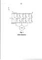
[012] Nos desenhos: A FIGURA 1 ilustra um sistema de controle de máquina de imã permanente convencional. FIGURA 2 ilustra um sistema de controle de máquina de imã permanente de alta densidade de energia, de acordo com uma realização da invenção.[012] In the drawings: FIGURE 1 illustrates a conventional permanent magnet machine control system. FIGURE 2 illustrates a high energy density permanent magnet machine control system, in accordance with an embodiment of the invention.
[013] A FIGURA 1 ilustra um sistema de controle de máquina de imã permanente 10 trifásico convencional. O sistema 10 inclui uma ligação CC 12 que fornece uma tensão de entrada CC que é convertida ou invertida para uma forma de onda CA que aciona uma máquina de imã permanente 14. Um capacitor de filtro de entrada 16 é acoplado através da ligação CC 12 para filtrar a tensão VCC na ligação CC 12. Um conversor de energia 18 recebe a tensão de entrada da ligação CC 12 quando energia flui da ligação CC 12 para a máquina de imã permanente CA 14. Esta direção do fluxo de energia é frequentemente referenciado como operando em um modo de “motorização”. Quando a direção do fluxo de energia é da máquina de imã permanente 14 para o conversor de energia 18, a tensão de entrada para o conversor de energia 18 é CA da máquina de imã permanente 14, enquanto a saída do conversor de energia 18 é uma tensão CC na ligação CC 12. A operação com o fluxo de energia da máquina de imã permanente CA 14 para o conversor de energia 18 frequentemente é referenciada como operação em um modo regenerativo de frenagem que é útil, por exemplo, em um veículo onde é desejável manter um dado valor de velocidade em um grau de descida, ou durante a desaceleração do veículo.[013] FIGURE 1 illustrates a conventional three-phase permanent magnet machine control system 10. System 10 includes a
[014] O conversor de energia 18 é um inversor trifásico típico 3 que tem dois dispositivos de comutação conectados em série por perna de fase. Por exemplo, dispositivos 20 e 22 formam uma primeira perna de fase, dispositivos 24 e 26 formam uma segunda perna de fase, e dispositivos 28 e 30 formam uma terceira perna de fase. Os dispositivos 20 a 30 são dispositivos de comutação de semicondutor de silício convencionais tais como, por exemplo, IGBT de silício, MOSFET, transistor de energia Darlington bi-polar de silício, GTO, SCR, ou dispositivos tipo IGCT. Os diodos 32, 34, 36, 38, 40, 42 são acoplados em relacionamento antiparalelo através dos respectivos dispositivos de comutação de silício 20 a 30.[014]
[015] A FIGURA 2 ilustra um sistema de controle de máquina de imã permanente 44 de acordo com uma realização da invenção. O sistema de controle 44 inclui uma ligação CC 46 que tem uma tensão VS 48 de fonte CC. Sistema de controle 44 inclui a fonte de alimentação 50 que fornece tensão VS 48 de fonte CC. O sistema de controle 44 inclui preferencialmente dois contatores (C1, C2) 52, 54, ou pelo menos um contator C1 para conectar ou desconectar uma ligação CC 46 da fonte de alimentação 50. Em uma realização, a fonte de alimentação 50 inclui uma fonte CA 58 e um retificador 56 configurado para converter uma tensão da fonte CA 58 para a ligação CC ou tensão de fonte Vs. Em outra realização, a fonte de alimentação 50 inclui uma fonte de alimentação CC 58, tal como uma bateria, uma célula combustível, ou um volante com conversor eletrônico de energia associado. Em ainda outra realização, a fonte de alimentação 50 inclui uma fonte de alimentação CC 58, tal como uma bateria, uma célula combustível, um ultra capacitor, ou um volante com conversor eletrônico de energia associado a um conversor de tensão CC para CC bi-direcional 56 que reforça a tensão da fonte para a ligação CC ou tensão da fonte Vs. A ligação CC 46 fornece uma tensão CC de saída VCC 60 a um conversor de energia ou inversor 62. Um capacitor de filtro de entrada 64 é ilustrado entre uma saída CC positiva 66 e uma saída CC negativa 68 e serve para fornecer uma função de filtro para as correntes de alta frequência da fonte 50 para garantir a qualidade da energia entre saídas positiva e negativa 66, 68.[015] FIGURE 2 illustrates a permanent magnet
[016] O conversor de energia 62 recebe tensão CC de entrada VCC 60 da ligação CC 46 e converte a tensão CC de entrada para fornecer uma forma adequada de energia CA para acionar uma máquina de imã permanente 70, descrita em detalhes abaixo. Um controlador 72 também é incluído no sistema de controle 44 e inclui meios para abrir e fechar os contatores C1 e C2 52, 54 baseado nas entradas de tensão medidas Vs 48, VCC 60, entradas de sensor de velocidade da máquina 70, somadas às entradas do operador bem como às falhas detectadas que podem ocorrer em um conversor de energia 62. O controlador 72 também inclui meios para controlar o comando de energia de reforço para o conversor de reforço bidirecional 56.[016] The
[017] De acordo com uma realização, o conversor de energia 62 é um inversor CC para CA trifásico que tem uma pluralidade de dispositivos de comutação 74, 76, 78, 80, 82, 84. Cada dispositivo de comutação 74 a 84 inclui um MOSFET de carboneto de silício (SiC) 86, 88, 90, 92, 94, 96 e um diodo anti-paralelo associado 98, 100, 102, 104, 106, 108.[017] According to one embodiment, the
[018] SiC é uma substância cristalina que tem propriedades de material que fazem com que o mesmo seja uma alternativa atraente ao silício para aplicações de alta tensão e alta potência, por exemplo, o SiC tem uma grande lacuna de banda que fornece uma perda de corrente muito pequena, o que facilita operação em altas temperaturas. De fato, dispositivos semicondutores fabricados em um substrato de SiC pode suportar temperaturas acima de 200 graus C. O SiC também tem um campo de colapso alto que de aproximadamente dez vezes o do silício e uma condutividade térmica que á aproximadamente três vezes a do silício, o que permite que maiores densidades de energia sejam acomodadas como circuitos de SiC. Adicionalmente, a alta mobilidade de elétrons de SiC permite comutação de alta velocidade. Portanto, o SiC tem sido considerado como um material vantajoso para uso na fabricação de dispositivos semicondutores de energia de próxima geração. Tais dispositivos incluem, por exemplo, diodos Schottky, tiristores, e MOSFETs.[018] SiC is a crystalline substance that has material properties that make it an attractive alternative to silicon for high voltage and high power applications, for example, SiC has a large band gap that provides a loss of very small current, which facilitates operation at high temperatures. In fact, semiconductor devices manufactured on a SiC substrate can withstand temperatures above 200 degrees C. SiC also has a high collapse field that is approximately ten times that of silicon and a thermal conductivity that is approximately three times that of silicon, which allows higher energy densities to be accommodated as SiC circuits. Additionally, the high electron mobility of SiC allows high speed switching. Therefore, SiC has been considered as an advantageous material for use in the manufacture of next generation energy semiconductor devices. Such devices include, for example, Schottky diodes, thyristors, and MOSFETs.
[019] Movendo da esquerda para a direita na FIGURA 2, dispositivos de comutação 74, 76 são associados com uma primeira fase de saída 110, dispositivos de comutação 78, 80 são associados com uma segunda fase de saída 112, e dispositivos de comutação 82, 84 são associados com uma terceira fase de saída 114. Embora sejam ilustrados um conversor de energia trifásico e uma máquina de imã permanente trifásica 70 na FIGURA 2, um técnico no assunto entenderá que realizações da presente invenção são aplicáveis igualmente a uma realização monofásica ou outras realizações multifásicas. Por exemplo, realizações alternativas incluem configurações com variadas quantidade de fases, por exemplo, n-fase, onde n = 1, 2, 4, 5, 7, ou quantidade maior, em que cada fase do conversor de energia inclui uma pluralidade de dispositivos de comutação similar aos dispositivos 86, 88, cada um com diodos anti-paralelos associados similares aos diodos 98, 100.[019] Moving from left to right in FIGURE 2, switching
[020] O conversor de energia 62 aciona uma máquina de imã permanente 70. Em uma realização, a máquina de imã permanente 70 é um motor de tração que inclui um rotor de imã permanente 116 e um estator 118, tal como, por exemplo, um motor de tração para propulsionar um veículo elétrico. O rotor de imã permanente 116, pode ser configurado como um rotor montado na superfície, interior, ou rotor de imã permanente aterrado, de acordo com várias realizações. Em uma realização alternativa, a máquina de imã permanente 70 é um alternador que inclui um rotor de imã permanente 116 e um estator 118, tais como, por exemplo, um alternador de imã permanente acoplado a um motor térmico dentro de uma Unidade de Energia Auxiliar (APU) para gerar energia elétrica para auxiliar na operação de um veículo elétrico- híbrido (HEV) ou um veículo elétrico-híbrido conectável (PHEV).[020] The
[021] A capacidade de alta tensão dos MOSFETs de SiC 86 a 96 permite que a máquina de imã permanente 70 seja projetada com uma emf inversa alta sem ter que se preocupar sobre o modo de geração descontrolado, o que aumenta significativamente a densidade de energia da máquina de imã permanente 70. Ou seja, os MOSFETs de SiC 86 a 96 têm uma capacidade de tensão que excede a tensão de ligação CC durante um modo de geração descontrolado de máquina de imã permanente 70. Os módulos de energia IGBT de Si convencionais usados em circuitos de conversor de energia disponíveis comercialmente na estrada EV, HEV, e PHEV têm tipicamente uma capacidade de tensão de aproximadamente 600 V ou 1.200 V para alguns veículos maiores ou de alta performance incluindo SUVs, caminhões e ônibus. De acordo com uma realização, MOSFETs de SiC 86 a 96 são MOSFETs de SiC de alta tensão fabricados pela General Electric Company que tem uma capacidade de tensão de aproximadamente três a quatro kV. O conversor de energia de SiC 62 de alta tensão combinado com máquina de imã permanente multifásica de alta densidade de energia 70, permite aumentos de duas a quatro vezes da densidade de energia com uma melhoria substancial na tolerância a falhas durante períodos de perda de controle sobre o conversor de energia 62 ou perda do controle de porta para os módulos de energia dentro do conversor de energia 62. Devido aos MOSFETs de SiC 86 a 96 poderem ser fabricados para ser fisicamente menores do que MOSFETs de silício convencionais, os MOSFETs de SiC 86 a 96 podem ser acomodados em um ambiente de automóvel e podem ser operados a altas temperaturas.[021] The high voltage capacity of SiC MOSFETs 86 to 96 allows the permanent magnet machine 70 to be designed with a high reverse emf without having to worry about uncontrolled generation mode, which significantly increases energy density permanent magnet machine 70. That is, SiC MOSFETs 86 to 96 have a voltage capacity that exceeds the DC link voltage during a permanent magnet machine 70 uncontrolled generation mode. Conventional IGBT Si power modules used in commercially available power converter circuits on the EV, HEV, and PHEV road typically have a voltage capacity of approximately 600 V or 1,200 V for some larger or high-performance vehicles including SUVs, trucks and buses. According to one embodiment, SiC MOSFETs 86 to 96 are high voltage SiC MOSFETs manufactured by the General Electric Company that have a voltage capacity of approximately three to four kV. The
[022] Tensão de emf excessiva da máquina de imã permanente 70 pode danificar a fonte de alimentação CC 58 da fonte de alimentação 50. Consequentemente, em uma realização, o controlador 72 é configurado para detectar uma falha no conversor de energia 62 e no conjunto de circuitos de controle de porta associado do conversor de energia 62. Por exemplo, uma falha pode ser detectada se uma emf inversa linha a linha ficar dentro de um percentual de limite da capacidade der tensão da fonte de alimentação CC 58. Se a falha é detectada, o controlador 72 pode ser programado para desconectar ou desacoplar a fonte de alimentação CC 58 do conversor de energia 62. Consequentemente, tensão de emf excessiva criada pela máquina de imã permanente 70 durante uma condição de falha dentro do conversor de energia 62 não resultará em dano de sobre-tensão a fonte de alimentação CC 58. A capacidade de alta tensão do conversor de energia de SiC 62 e seus componentes associados 86 a 96 resistirão a emf inversa da máquina de imã permanente de alta energia 70, mesmo se uma falha potencial ocorrer enquanto a máquina 70 estiver operando em alta velocidade.[022] Excessive emf voltage of the permanent magnet machine 70 can damage the
[023] Portanto, de acordo com uma realização da invenção, um sistema de controle elétrico inclui uma máquina de imã permanente que tem um rotor e um estator e um conversor de energia acoplado eletricamente a uma máquina de imã permanente e configurado para converter a tensão de ligação CC para uma tensão de saída CA para controlar a máquina de imã permanente. O conversor de energia inclui uma pluralidade de dispositivos de comutação de SiC que têm uma capacidade de tensão que excede uma emf inversa de linha a linha de pico da máquina de imã permanente a uma velocidade máxima da máquina de imã permanente.[023] Therefore, according to an embodiment of the invention, an electrical control system includes a permanent magnet machine that has a rotor and a stator and an energy converter electrically coupled to a permanent magnet machine and configured to convert the voltage DC link voltage to an AC output voltage to control the permanent magnet machine. The power converter includes a plurality of SiC switching devices that have a voltage capacity that exceeds a line-to-line reverse emf of the permanent magnet machine at the maximum speed of the permanent magnet machine.
[024] De acordo com outra realização da invenção, um método para fabricar um sistema de controle elétrico inclui a etapa de fornecer um conversor de energia de SiC que tem uma pluralidade de dispositivos de comutação de SiC e é acoplável a uma fonte de alimentação. O método também inclui as etapas de fornecer uma máquina de imã permanente que tem uma emf inversa de linha a linha de pico à velocidade máxima que é maior do que a tensão de ligação CC da fonte de alimentação e acoplar o conversor de energia de SiC a uma máquina de imã permanente para controlar a máquina de imã permanente.[024] According to another embodiment of the invention, a method for fabricating an electrical control system includes the step of providing a SiC power converter that has a plurality of SiC switching devices and is attachable to a power supply. The method also includes the steps of providing a permanent magnet machine that has a line-to-line peak reverse emf at maximum speed that is greater than the DC link voltage of the power supply and coupling the SiC power converter to a permanent magnet machine to control the permanent magnet machine.
[025] De acordo com ainda outra realização da invenção, um sistema de propulsão de veículo inclui um motor que tem um rotor de imã permanente e um estator. O sistema de controle também inclui uma ligação CC e um conversor de energia acoplado eletricamente entre a ligação CC e o motor de imã permanente para controlar o motor de imã permanente. O conversor de energia compreende uma pluralidade de dispositivos de comutação de SiC capacitado para uma tensão de operação mais alta do que uma emf inversa máxima capaz de ser desenvolvida no estator do motor de imã permanente.[025] In accordance with yet another embodiment of the invention, a vehicle propulsion system includes an engine that has a permanent magnet rotor and a stator. The control system also includes a DC link and an electrically coupled power converter between the DC link and the permanent magnet motor to control the permanent magnet motor. The power converter comprises a plurality of SiC switching devices capable of operating at a higher operating voltage than a maximum reverse emf capable of being developed in the permanent magnet motor stator.
[026] Esta descrição escrita usa exemplos para revelar a invenção, incluindo o melhor modo, e também para permitir que qualquer técnico no assunto pratique a invenção, incluindo fazer e usar quaisquer dispositivos ou sistemas e executar quaisquer métodos incorporados. O escopo patenteável da invenção é definido pelas reivindicações, e pode incluir outros exemplos que ocorrem aos técnicos no assunto. Estes tais outros exemplos são entendidos como estando dentro do escopo das reivindicações se os mesmos tiverem elementos estruturais que não diferem da linguagem literal das reivindicações, ou se os mesmos incluírem elementos estruturais equivalentes com diferenças irrelevantes das linguagens literais das reivindicações.[026] This written description uses examples to reveal the invention, including the best way, and also to allow any person skilled in the art to practice the invention, including making and using any devices or systems and performing any built-in methods. The patentable scope of the invention is defined by the claims, and may include other examples that occur to those skilled in the art. These other examples are understood to be within the scope of the claims if they have structural elements that do not differ from the literal language of the claims, or if they include equivalent structural elements with irrelevant differences from the literal languages of the claims.
Claims (10)
Applications Claiming Priority (2)
| Application Number | Priority Date | Filing Date | Title |
|---|---|---|---|
| US12/949,925 | 2010-11-19 | ||
| US12/949,925 US9780716B2 (en) | 2010-11-19 | 2010-11-19 | High power-density, high back emf permanent magnet machine and method of making same |
Publications (3)
| Publication Number | Publication Date |
|---|---|
| BRPI1104890A2 BRPI1104890A2 (en) | 2013-03-12 |
| BRPI1104890B1 true BRPI1104890B1 (en) | 2020-12-08 |
| BRPI1104890B8 BRPI1104890B8 (en) | 2021-06-15 |
Family
ID=45406392
Family Applications (1)
| Application Number | Title | Priority Date | Filing Date |
|---|---|---|---|
| BRPI1104890A BRPI1104890B8 (en) | 2010-11-19 | 2011-11-17 | electrical control system |
Country Status (5)
| Country | Link |
|---|---|
| US (3) | US9780716B2 (en) |
| EP (1) | EP2456065B1 (en) |
| JP (1) | JP2012115133A (en) |
| CN (2) | CN108306573B (en) |
| BR (1) | BRPI1104890B8 (en) |
Families Citing this family (16)
| Publication number | Priority date | Publication date | Assignee | Title |
|---|---|---|---|---|
| CN103684002B (en) | 2012-09-24 | 2016-12-21 | 通用电气公司 | Energy conversion system |
| CN103855913A (en) * | 2012-11-30 | 2014-06-11 | 通用电气公司 | Energy transformation system and control method |
| US9174525B2 (en) | 2013-02-25 | 2015-11-03 | Fairfield Manufacturing Company, Inc. | Hybrid electric vehicle |
| CN106160206A (en) | 2015-03-31 | 2016-11-23 | 通用电气公司 | Power-supply system and energy storage system |
| CN107925375B (en) * | 2015-10-19 | 2020-10-13 | 三菱电机株式会社 | Air conditioner |
| CN105649776A (en) * | 2016-01-19 | 2016-06-08 | 扬州市新港电机有限公司 | Gas power generation system based on SiC device |
| US10340819B2 (en) * | 2016-04-29 | 2019-07-02 | Gm Global Technology Operations Llc. | Fault shutdown control of an electric machine in a vehicle or other DC-powered torque system |
| DE102016211498A1 (en) * | 2016-06-27 | 2017-12-28 | Robert Bosch Gmbh | Method and device for external monitoring of power electronics |
| DE102016119822A1 (en) * | 2016-10-06 | 2018-04-12 | Lsp Innovative Automotive Systems Gmbh | High power generator low voltage with starter support function and torque compensation |
| JP6952544B2 (en) * | 2017-09-14 | 2021-10-20 | 東海旅客鉄道株式会社 | Power conversion system |
| EP3474434B1 (en) | 2017-10-23 | 2021-12-29 | Audi Ag | Electrical propulsion system |
| US20190184832A1 (en) * | 2017-12-19 | 2019-06-20 | Ford Global Technologies, Llc | Vehicle power system with back electromagnetic field blocking |
| CN108400736B (en) * | 2018-03-26 | 2019-09-20 | 山东元齐新动力科技有限公司 | The implementation method and computer storage medium of high power density motor controller |
| US11923716B2 (en) | 2019-09-13 | 2024-03-05 | Milwaukee Electric Tool Corporation | Power converters with wide bandgap semiconductors |
| DE102019215517B3 (en) * | 2019-10-10 | 2021-01-14 | Volkswagen Aktiengesellschaft | On-board electrical system and method for operating such an on-board network |
| CN112498123B (en) * | 2019-11-07 | 2022-02-22 | 河南嘉晨智能控制股份有限公司 | Method for stabilizing sliding speed of forklift ramp |
Family Cites Families (129)
| Publication number | Priority date | Publication date | Assignee | Title |
|---|---|---|---|---|
| US3621333A (en) * | 1969-05-12 | 1971-11-16 | Victoreen Leece Neville Inc | Control for deenergizing an alternator when exposed to water |
| US4667123A (en) * | 1985-11-20 | 1987-05-19 | The Garrett Corporation | Two pole permanent magnet rotor construction for toothless stator electrical machine |
| JPH02106159A (en) | 1988-10-14 | 1990-04-18 | Oriental Motor Co Ltd | Driving method for switching element gates |
| US5118708A (en) | 1989-06-23 | 1992-06-02 | Norwich Eaton Pharmaceuticals, Inc. | Use of 5-phenyl-2-furan esters, amides and ketones as neuroprotective agents |
| US5041896A (en) | 1989-07-06 | 1991-08-20 | General Electric Company | Symmetrical blocking high voltage semiconductor device and method of fabrication |
| US5726463A (en) * | 1992-08-07 | 1998-03-10 | General Electric Company | Silicon carbide MOSFET having self-aligned gate structure |
| JPH06284504A (en) | 1993-03-31 | 1994-10-07 | Mitsubishi Electric Corp | Safety device for rolling stock |
| US5378642A (en) | 1993-04-19 | 1995-01-03 | General Electric Company | Method of making a silicon carbide junction field effect transistor device for high temperature applications |
| US5514604A (en) | 1993-12-08 | 1996-05-07 | General Electric Company | Vertical channel silicon carbide metal-oxide-semiconductor field effect transistor with self-aligned gate for microwave and power applications, and method of making |
| JP3374491B2 (en) | 1993-12-24 | 2003-02-04 | 株式会社デンソー | Electric generator for vehicle |
| US5385855A (en) * | 1994-02-24 | 1995-01-31 | General Electric Company | Fabrication of silicon carbide integrated circuits |
| JP3419082B2 (en) | 1994-06-06 | 2003-06-23 | 株式会社デンソー | Orthogonal transformation device |
| US5672889A (en) | 1995-03-15 | 1997-09-30 | General Electric Company | Vertical channel silicon carbide metal-oxide-semiconductor field effect transistor with self-aligned gate for microwave and power applications, and method of making |
| US5510281A (en) | 1995-03-20 | 1996-04-23 | General Electric Company | Method of fabricating a self-aligned DMOS transistor device using SiC and spacers |
| JP3412330B2 (en) * | 1995-04-24 | 2003-06-03 | 株式会社デンソー | Power generation equipment for vehicles |
| JP3458531B2 (en) | 1995-06-02 | 2003-10-20 | 株式会社デンソー | Alternator |
| US5731689A (en) * | 1995-06-06 | 1998-03-24 | Nippondenso Co., Ltd. | Control system for A.C. generator |
| JPH08336259A (en) | 1995-06-06 | 1996-12-17 | Nippondenso Co Ltd | Ac generator for vehicle |
| DE19610135C1 (en) | 1996-03-14 | 1997-06-19 | Siemens Ag | Electronic device, esp. for switching hv electric currents |
| US5757151A (en) * | 1996-05-02 | 1998-05-26 | Chrysler Corporation | DC pump drive module |
| DE19727202A1 (en) | 1997-06-26 | 1999-01-28 | Grundfos As | Submersible motor unit |
| JPH11178353A (en) * | 1997-12-11 | 1999-07-02 | Hitachi Ltd | Resonant inverter and electric rolling stock using the same |
| JP4128645B2 (en) | 1998-01-12 | 2008-07-30 | 株式会社日立製作所 | Inverter for rotating electrical machine |
| JPH11307352A (en) | 1998-04-17 | 1999-11-05 | Nkk Corp | High efficiency motor |
| DE19817333C5 (en) | 1998-04-18 | 2007-04-26 | Conti Temic Microelectronic Gmbh | Electric drive unit consisting of electric motor and electronic module |
| JP2000197347A (en) * | 1998-12-25 | 2000-07-14 | Hitachi Ltd | Power supply device |
| DE19949321C1 (en) | 1999-10-13 | 2001-05-03 | Temic Auto Electr Motors Gmbh | Cooling fan for automobile has electronic control circuit for fan motor contained in housing provided with cooling ribs projecting into path of cooling air provided by fan wheel |
| US6239582B1 (en) | 1999-11-04 | 2001-05-29 | Satcon Technology Corporation | Motor vehicle alternator having a single voltage sensor and a half-wave controlled rectifier bridge for increasing output |
| JP3833870B2 (en) | 2000-04-25 | 2006-10-18 | 松下冷機株式会社 | refrigerator |
| US6498451B1 (en) | 2000-09-06 | 2002-12-24 | Delphi Technologies, Inc. | Torque ripple free electric power steering |
| DE10062026A1 (en) | 2000-12-13 | 2002-07-04 | Siemens Ag | Electronic switching device |
| DE10063084B4 (en) | 2000-12-18 | 2009-12-03 | Siemens Ag | Power electronic circuit |
| DE10101744C1 (en) | 2001-01-16 | 2002-08-08 | Siemens Ag | Electronic switching device and operating method |
| DE10124197A1 (en) * | 2001-05-17 | 2002-12-12 | Siemens Ag | Converter with a line and load side self-commutated pulse converter |
| JP3997730B2 (en) | 2001-06-20 | 2007-10-24 | 株式会社日立製作所 | Power conversion apparatus and moving body equipped with the same |
| DE10134883A1 (en) | 2001-07-18 | 2003-01-30 | Abb Research Ltd | Method and device for speed-adjustable power electronic control of a gearless wind turbine |
| JP3625789B2 (en) * | 2001-08-10 | 2005-03-02 | 本田技研工業株式会社 | Vehicle power supply |
| DE10302791B4 (en) | 2002-01-30 | 2016-03-17 | Denso Corporation | electric compressor |
| JP4082060B2 (en) | 2002-04-02 | 2008-04-30 | 三菱電機株式会社 | Power converter |
| US6989592B2 (en) * | 2002-05-01 | 2006-01-24 | The Boeing Company | Integrated power module with reduced thermal impedance |
| JP3818213B2 (en) | 2002-05-01 | 2006-09-06 | 株式会社デンソー | Electric compressor |
| US7038260B1 (en) | 2003-03-04 | 2006-05-02 | Lovoltech, Incorporated | Dual gate structure for a FET and method for fabricating same |
| JP2004289935A (en) | 2003-03-20 | 2004-10-14 | Sumitomo Electric Ind Ltd | Inverter |
| JP2005160284A (en) | 2003-05-13 | 2005-06-16 | Sumitomo Electric Ind Ltd | Power conversion apparatus and drive system of electric automobile |
| JP2005045927A (en) * | 2003-07-23 | 2005-02-17 | Toyota Motor Corp | Motor drive system and electric automobile |
| US7449241B2 (en) | 2003-08-04 | 2008-11-11 | General Electric Company | Organic coating compositions for aluminizing metal substrates, and related methods and articles |
| US6946760B2 (en) * | 2003-10-22 | 2005-09-20 | Emerson Electric Co. | Brushless permanent magnet motor with high power density, low cogging and low vibration |
| US7187021B2 (en) | 2003-12-10 | 2007-03-06 | General Electric Company | Static induction transistor |
| JP4140562B2 (en) | 2003-12-16 | 2008-08-27 | トヨタ自動車株式会社 | Cooling system and hybrid vehicle |
| JP4156542B2 (en) * | 2004-03-03 | 2008-09-24 | 三菱電機株式会社 | Rotating electrical machine for vehicle |
| US7057371B2 (en) * | 2004-04-19 | 2006-06-06 | General Motors Corporation | Inverter for electric and hybrid powered vehicles and associated system and method |
| JP2005348583A (en) | 2004-06-07 | 2005-12-15 | Fuji Heavy Ind Ltd | Controller for electric vehicle |
| SE527648C2 (en) | 2004-07-09 | 2006-05-02 | Danaher Motion Stockholm Ab | Asynchronous motor with integrated sensor |
| US7554220B2 (en) * | 2004-07-19 | 2009-06-30 | The Kansai Electric Power Co., Inc. | Stable power supplying apparatus |
| JP4494112B2 (en) | 2004-07-28 | 2010-06-30 | 三菱電機株式会社 | Inverter control device for air conditioner and air conditioner |
| US7203569B2 (en) | 2004-08-31 | 2007-04-10 | General Electric Company | Machine tool control methods and designs for fabricating mesoscopic surface structures on substrates |
| EP1805880A2 (en) | 2004-10-20 | 2007-07-11 | Ballard Power Systems Corporation | Power system method and apparatus |
| JP4547231B2 (en) | 2004-10-22 | 2010-09-22 | 日立オートモティブシステムズ株式会社 | Power converter |
| JP2006121877A (en) | 2004-10-25 | 2006-05-11 | Denso Corp | Motor controller |
| JP4656298B2 (en) | 2004-12-24 | 2011-03-23 | 株式会社安川電機 | Power converter |
| JP2006217743A (en) | 2005-02-04 | 2006-08-17 | Toyota Motor Corp | Electric load control device |
| US7210304B2 (en) | 2005-02-09 | 2007-05-01 | General Motors Corporation | Cooling arrangements for integrated electric motor-inverters |
| JP2006320134A (en) | 2005-05-13 | 2006-11-24 | Matsushita Electric Ind Co Ltd | Motor drive circuit and electric washing machine therewith |
| US20060267021A1 (en) | 2005-05-27 | 2006-11-30 | General Electric Company | Power devices and methods of manufacture |
| WO2007002187A2 (en) * | 2005-06-22 | 2007-01-04 | Siemens Vdo Automotive Corporation | Power generation system suitable for hybrid electric vehicles |
| US20070015373A1 (en) | 2005-07-13 | 2007-01-18 | General Electric Company | Semiconductor device and method of processing a semiconductor substrate |
| DE102005032971A1 (en) | 2005-07-14 | 2007-01-18 | Siemens Ag | Inverter motor, has inverter electronics whose components are distributively arranged on printed circuit boards, which can be folded against each other and form printed circuit board line using flexible, electrical connection units |
| JP4708951B2 (en) | 2005-10-21 | 2011-06-22 | ニチコン株式会社 | Inverter module and inverter-integrated AC motor using the same |
| JP4539531B2 (en) | 2005-10-26 | 2010-09-08 | トヨタ自動車株式会社 | Vehicle drive device |
| US7521732B2 (en) | 2005-11-18 | 2009-04-21 | General Electric Company | Vertical heterostructure field effect transistor and associated method |
| US20070120208A1 (en) | 2005-11-28 | 2007-05-31 | General Electric Company | Wide bandgap semiconductor based field effect transistors |
| US20070126007A1 (en) | 2005-12-07 | 2007-06-07 | Matocha Kevin S | SiC semiconductor device and method of fabricating same |
| JP2007166804A (en) | 2005-12-14 | 2007-06-28 | Toyota Motor Corp | Motor drive and vehicle having the same |
| US20070151272A1 (en) * | 2006-01-03 | 2007-07-05 | York International Corporation | Electronic control transformer using DC link voltage |
| JP5017529B2 (en) * | 2006-02-28 | 2012-09-05 | 日産自動車株式会社 | Power converter for magnet synchronous motor |
| US7193378B1 (en) * | 2006-03-14 | 2007-03-20 | Gm Global Technology Operations, Inc. | Wye switch inverter for electric and hybrid vehicles |
| US20070224784A1 (en) | 2006-03-22 | 2007-09-27 | Soloviev Stanislav I | Semiconductor material having an epitaxial layer formed thereon and methods of making same |
| US7351637B2 (en) | 2006-04-10 | 2008-04-01 | General Electric Company | Semiconductor transistors having reduced channel widths and methods of fabricating same |
| KR101201908B1 (en) * | 2006-05-04 | 2012-11-16 | 엘지전자 주식회사 | Control apparatus and method of synchronous reluctance motor |
| JP4462243B2 (en) | 2006-07-10 | 2010-05-12 | トヨタ自動車株式会社 | Load driving device and vehicle equipped with the same |
| US20080014693A1 (en) | 2006-07-12 | 2008-01-17 | General Electric Company | Silicon carbide vertical mosfet design for fast switching applications |
| JP2008029115A (en) | 2006-07-21 | 2008-02-07 | Japan Servo Co Ltd | Single-phase position sensorless permanent magnet motor controller |
| US20080018289A1 (en) | 2006-07-21 | 2008-01-24 | Fumio Tajima | Single-phase position sensorless permanent magnet motor control apparatus |
| US7517807B1 (en) | 2006-07-26 | 2009-04-14 | General Electric Company | Methods for fabricating semiconductor structures |
| US20080038890A1 (en) | 2006-08-10 | 2008-02-14 | General Electric Company | Method for improved trench protection in vertical umosfet devices |
| US7595241B2 (en) | 2006-08-23 | 2009-09-29 | General Electric Company | Method for fabricating silicon carbide vertical MOSFET devices |
| JP4935251B2 (en) | 2006-08-31 | 2012-05-23 | ダイキン工業株式会社 | Power converter |
| US20080108190A1 (en) | 2006-11-06 | 2008-05-08 | General Electric Company | SiC MOSFETs and self-aligned fabrication methods thereof |
| JP4675311B2 (en) | 2006-11-16 | 2011-04-20 | トヨタ自動車株式会社 | Inverter and condenser cooling structure accommodated integrally with motor in motor housing, motor unit and housing having the cooling structure |
| US7807556B2 (en) | 2006-12-05 | 2010-10-05 | General Electric Company | Method for doping impurities |
| JP5205595B2 (en) | 2006-12-07 | 2013-06-05 | 日産自動車株式会社 | Power converter and motor drive system |
| US20080142811A1 (en) | 2006-12-13 | 2008-06-19 | General Electric Company | MOSFET devices and methods of fabrication |
| US7781312B2 (en) | 2006-12-13 | 2010-08-24 | General Electric Company | Silicon carbide devices and method of making |
| JP4665911B2 (en) | 2007-02-07 | 2011-04-06 | トヨタ自動車株式会社 | Cooling system |
| JP2007166900A (en) | 2007-02-13 | 2007-06-28 | Mitsubishi Electric Corp | Power unit for vehicle |
| US7760005B2 (en) | 2007-03-29 | 2010-07-20 | General Electric Company | Power electronic module including desaturation detection diode |
| US7868510B2 (en) * | 2007-03-30 | 2011-01-11 | Rittenhouse Norman P | High-efficiency wheel-motor utilizing molded magnetic flux channels with transverse-flux stator |
| JP4297951B2 (en) | 2007-05-25 | 2009-07-15 | トヨタ自動車株式会社 | Vehicle drive system |
| US7679941B2 (en) * | 2007-06-06 | 2010-03-16 | General Electric Company | Power conversion system with galvanically isolated high frequency link |
| US7787270B2 (en) * | 2007-06-06 | 2010-08-31 | General Electric Company | DC-DC and DC-AC power conversion system |
| US7652858B2 (en) * | 2007-06-06 | 2010-01-26 | Gm Global Technology Operations, Inc. | Protection for permanent magnet motor control circuits |
| JP5266687B2 (en) | 2007-08-16 | 2013-08-21 | 三菱電機株式会社 | Anomaly detection device |
| EP2164167B1 (en) | 2007-11-01 | 2016-08-31 | Aisin AW Co., Ltd. | Motor control device, drive device, and hybrid drive device |
| US20090159896A1 (en) | 2007-12-20 | 2009-06-25 | General Electric Company | Silicon carbide mosfet devices and methods of making |
| US8083557B2 (en) * | 2008-01-18 | 2011-12-27 | Steven Sullivan | Method and apparatus for powering of amphibious craft |
| US7691711B2 (en) | 2008-01-31 | 2010-04-06 | General Electric Company | Method for fabricating silicon carbide vertical MOSFET devices |
| JP4535153B2 (en) * | 2008-03-21 | 2010-09-01 | 株式会社デンソー | Power conversion circuit control device and power conversion system |
| US20090242292A1 (en) * | 2008-03-28 | 2009-10-01 | Marcus Heller | Method and system for operating an electric machine |
| JP2009254170A (en) * | 2008-04-08 | 2009-10-29 | Hitachi-Lg Data Storage Inc | Motor drive circuit |
| US7777553B2 (en) | 2008-04-08 | 2010-08-17 | Infineon Technologies Austria Ag | Simplified switching circuit |
| JP4654423B2 (en) * | 2008-07-22 | 2011-03-23 | 独立行政法人産業技術総合研究所 | Power converter |
| JP5077162B2 (en) | 2008-09-11 | 2012-11-21 | トヨタ自動車株式会社 | DRIVE DEVICE, ITS CONTROL METHOD, AND VEHICLE |
| GB2463483B (en) | 2008-09-12 | 2011-09-07 | Controlled Power Technologies Ltd | Liquid cooled electrical machine |
| JP5045622B2 (en) | 2008-09-16 | 2012-10-10 | パナソニック株式会社 | Power converter |
| US8336323B2 (en) * | 2008-10-03 | 2012-12-25 | Johnson Controls Technology Company | Variable speed drive with pulse-width modulated speed control |
| US7906427B2 (en) | 2008-10-14 | 2011-03-15 | General Electric Company | Dimension profiling of SiC devices |
| US8217398B2 (en) | 2008-10-15 | 2012-07-10 | General Electric Company | Method for the formation of a gate oxide on a SiC substrate and SiC substrates and devices prepared thereby |
| JP2010130837A (en) | 2008-11-28 | 2010-06-10 | Toshiba Corp | Motor drive controller for railcar |
| JP4512671B1 (en) * | 2008-12-17 | 2010-07-28 | パナソニック株式会社 | Power conversion circuit |
| US7829402B2 (en) | 2009-02-10 | 2010-11-09 | General Electric Company | MOSFET devices and methods of making |
| JP5412922B2 (en) | 2009-03-31 | 2014-02-12 | 日産自動車株式会社 | Electric motor |
| JP4625147B2 (en) * | 2009-04-13 | 2011-02-02 | パナソニック株式会社 | Synchronous motor drive system |
| IT1393872B1 (en) | 2009-04-22 | 2012-05-11 | Ansaldo Ricerche S P A | COOLING SYSTEM FOR HIGH VOLTAGE POWER DENSITY ELECTRIC MOTOR, IN PARTICULAR ELECTRIC AXIAL FLOW MOTOR |
| JP5493532B2 (en) | 2009-07-17 | 2014-05-14 | 富士電機株式会社 | Load driving device and electric vehicle using the same |
| US8610130B2 (en) | 2009-10-30 | 2013-12-17 | Cree, Inc. | Monolithic high voltage switching devices |
| US8446113B2 (en) | 2010-06-17 | 2013-05-21 | GM Global Technology Operations LLC | Vehicular electrical system and method for controlling an inverter during motor deceleration |
| US20120119573A1 (en) * | 2010-11-17 | 2012-05-17 | Andy Turudic | Ultra High Efficiency Transmission, with Grid Tied Energy Storage Capability, for a Wind Turbine or a Fuel Cell or Battery Powered Electric Vehicle |
| US20120126728A1 (en) | 2010-11-19 | 2012-05-24 | El-Refaie Ayman Mohamed Fawzi | Integrated electric machine and silicon carbide power converter assembly and method of making same |
| US9685900B2 (en) | 2010-11-19 | 2017-06-20 | General Electric Company | Low-inductance, high-efficiency induction machine and method of making same |
-
2010
- 2010-11-19 US US12/949,925 patent/US9780716B2/en active Active
-
2011
- 2011-11-14 JP JP2011248140A patent/JP2012115133A/en active Pending
- 2011-11-15 EP EP11189127.1A patent/EP2456065B1/en active Active
- 2011-11-17 BR BRPI1104890A patent/BRPI1104890B8/en active Search and Examination
- 2011-11-18 CN CN201810153887.6A patent/CN108306573B/en active Active
- 2011-11-18 CN CN201110457017.6A patent/CN102545774B/en active Active
-
2017
- 2017-04-20 US US15/492,544 patent/US10946748B2/en active Active
- 2017-05-19 US US15/600,086 patent/US20170257050A1/en not_active Abandoned
Also Published As
| Publication number | Publication date |
|---|---|
| CN108306573A (en) | 2018-07-20 |
| US20120126733A1 (en) | 2012-05-24 |
| EP2456065A3 (en) | 2012-05-30 |
| US10946748B2 (en) | 2021-03-16 |
| US20170257050A1 (en) | 2017-09-07 |
| CN102545774A (en) | 2012-07-04 |
| EP2456065A2 (en) | 2012-05-23 |
| CN108306573B (en) | 2022-04-12 |
| BRPI1104890A2 (en) | 2013-03-12 |
| US20170217320A1 (en) | 2017-08-03 |
| US9780716B2 (en) | 2017-10-03 |
| CN102545774B (en) | 2018-03-30 |
| EP2456065B1 (en) | 2018-11-14 |
| JP2012115133A (en) | 2012-06-14 |
| BRPI1104890B8 (en) | 2021-06-15 |
Similar Documents
| Publication | Publication Date | Title |
|---|---|---|
| BRPI1104890B1 (en) | electrical control system | |
| US8164282B2 (en) | Motive power output apparatus and vehicle with the same | |
| US10917030B1 (en) | Electric drive system with reconfigurable machine windings | |
| BRPI1105062A2 (en) | ELECTRICAL DRIVE SYSTEM | |
| US9862276B2 (en) | Fault protection for electric drive systems | |
| US20170021733A1 (en) | Apparatus for controlling power converters | |
| JP6755388B2 (en) | Drive device for multi-group multi-phase rotary electric machine | |
| JP6348424B2 (en) | Power converter | |
| JP2013051831A (en) | Power source control device of electric vehicle | |
| Gan et al. | Cost-effective current measurement technique for four-phase SRM control by split dual bus line without pulse injection and voltage penalty | |
| JP2008514181A (en) | Power converter | |
| JP6289597B1 (en) | VEHICLE POWER DEVICE AND CONTROL METHOD FOR VEHICLE POWER DEVICE | |
| US10998840B2 (en) | Electric drive system with reconfigurable machine windings | |
| JP4128645B2 (en) | Inverter for rotating electrical machine | |
| JP6307983B2 (en) | Inverter control device | |
| JP7103320B2 (en) | Power supply | |
| JP6387919B2 (en) | Load drive device | |
| Fernandez et al. | Control drive for SMPMSM in CSI converter with SiC devices | |
| JP7446358B2 (en) | AC rotating electric machine control device | |
| JP2023170343A (en) | Power conversion apparatus | |
| Choi et al. | Discontinuous Active Short Circuit Strategy for Improved Safe State of PMSMs | |
| Shuanghong et al. | Implementation of a 50 kw 4-phase switched reluctance motor drive system for hev | |
| JP2023056365A (en) | charging device | |
| JP2014183638A (en) | Power conversion device |
Legal Events
| Date | Code | Title | Description |
|---|---|---|---|
| B03A | Publication of a patent application or of a certificate of addition of invention [chapter 3.1 patent gazette] | ||
| B06F | Objections, documents and/or translations needed after an examination request according [chapter 6.6 patent gazette] | ||
| B06U | Preliminary requirement: requests with searches performed by other patent offices: procedure suspended [chapter 6.21 patent gazette] | ||
| B09A | Decision: intention to grant [chapter 9.1 patent gazette] | ||
| B16A | Patent or certificate of addition of invention granted [chapter 16.1 patent gazette] |
Free format text: PRAZO DE VALIDADE: 20 (VINTE) ANOS CONTADOS A PARTIR DE 17/11/2011, OBSERVADAS AS CONDICOES LEGAIS. |
|
| B09W | Correction of the decision to grant [chapter 9.1.4 patent gazette] |
Free format text: RETIFICACAO (REF. RPI 2601 DE 10/11/2020 QUANTO AOS DESENHOS. ) |
|
| B16C | Correction of notification of the grant [chapter 16.3 patent gazette] |
Free format text: REF. RPI 2605 DE 08/12/2020 QUANTO AOS DESENHOS. |