BRPI1016074B1 - IMPROVED GAS PURIFICATION DEVICE - Google Patents
IMPROVED GAS PURIFICATION DEVICE Download PDFInfo
- Publication number
- BRPI1016074B1 BRPI1016074B1 BRPI1016074-4A BRPI1016074A BRPI1016074B1 BR PI1016074 B1 BRPI1016074 B1 BR PI1016074B1 BR PI1016074 A BRPI1016074 A BR PI1016074A BR PI1016074 B1 BRPI1016074 B1 BR PI1016074B1
- Authority
- BR
- Brazil
- Prior art keywords
- tank
- gas
- lock
- walls
- submerged
- Prior art date
Links
Images


Classifications
-
- B—PERFORMING OPERATIONS; TRANSPORTING
- B01—PHYSICAL OR CHEMICAL PROCESSES OR APPARATUS IN GENERAL
- B01D—SEPARATION
- B01D53/00—Separation of gases or vapours; Recovering vapours of volatile solvents from gases; Chemical or biological purification of waste gases, e.g. engine exhaust gases, smoke, fumes, flue gases, aerosols
- B01D53/14—Separation of gases or vapours; Recovering vapours of volatile solvents from gases; Chemical or biological purification of waste gases, e.g. engine exhaust gases, smoke, fumes, flue gases, aerosols by absorption
- B01D53/18—Absorbing units; Liquid distributors therefor
-
- B—PERFORMING OPERATIONS; TRANSPORTING
- B01—PHYSICAL OR CHEMICAL PROCESSES OR APPARATUS IN GENERAL
- B01D—SEPARATION
- B01D47/00—Separating dispersed particles from gases, air or vapours by liquid as separating agent
- B01D47/02—Separating dispersed particles from gases, air or vapours by liquid as separating agent by passing the gas or air or vapour over or through a liquid bath
- B01D47/028—Separating dispersed particles from gases, air or vapours by liquid as separating agent by passing the gas or air or vapour over or through a liquid bath by directing the gas through a wetted wire mesh or a perforated plate
-
- B—PERFORMING OPERATIONS; TRANSPORTING
- B01—PHYSICAL OR CHEMICAL PROCESSES OR APPARATUS IN GENERAL
- B01D—SEPARATION
- B01D47/00—Separating dispersed particles from gases, air or vapours by liquid as separating agent
- B01D47/06—Spray cleaning
-
- B—PERFORMING OPERATIONS; TRANSPORTING
- B01—PHYSICAL OR CHEMICAL PROCESSES OR APPARATUS IN GENERAL
- B01D—SEPARATION
- B01D53/00—Separation of gases or vapours; Recovering vapours of volatile solvents from gases; Chemical or biological purification of waste gases, e.g. engine exhaust gases, smoke, fumes, flue gases, aerosols
- B01D53/34—Chemical or biological purification of waste gases
- B01D53/74—General processes for purification of waste gases; Apparatus or devices specially adapted therefor
- B01D53/77—Liquid phase processes
- B01D53/78—Liquid phase processes with gas-liquid contact
-
- B—PERFORMING OPERATIONS; TRANSPORTING
- B01—PHYSICAL OR CHEMICAL PROCESSES OR APPARATUS IN GENERAL
- B01D—SEPARATION
- B01D2247/00—Details relating to the separation of dispersed particles from gases, air or vapours by liquid as separating agent
- B01D2247/04—Regenerating the washing fluid
-
- B—PERFORMING OPERATIONS; TRANSPORTING
- B01—PHYSICAL OR CHEMICAL PROCESSES OR APPARATUS IN GENERAL
- B01D—SEPARATION
- B01D2257/00—Components to be removed
- B01D2257/30—Sulfur compounds
- B01D2257/302—Sulfur oxides
-
- B—PERFORMING OPERATIONS; TRANSPORTING
- B01—PHYSICAL OR CHEMICAL PROCESSES OR APPARATUS IN GENERAL
- B01D—SEPARATION
- B01D2257/00—Components to be removed
- B01D2257/40—Nitrogen compounds
- B01D2257/404—Nitrogen oxides other than dinitrogen oxide
-
- B—PERFORMING OPERATIONS; TRANSPORTING
- B01—PHYSICAL OR CHEMICAL PROCESSES OR APPARATUS IN GENERAL
- B01D—SEPARATION
- B01D2257/00—Components to be removed
- B01D2257/50—Carbon oxides
- B01D2257/504—Carbon dioxide
-
- B—PERFORMING OPERATIONS; TRANSPORTING
- B01—PHYSICAL OR CHEMICAL PROCESSES OR APPARATUS IN GENERAL
- B01D—SEPARATION
- B01D2257/00—Components to be removed
- B01D2257/90—Odorous compounds not provided for in groups B01D2257/00 - B01D2257/708
-
- B—PERFORMING OPERATIONS; TRANSPORTING
- B01—PHYSICAL OR CHEMICAL PROCESSES OR APPARATUS IN GENERAL
- B01D—SEPARATION
- B01D2258/00—Sources of waste gases
- B01D2258/01—Engine exhaust gases
- B01D2258/012—Diesel engines and lean burn gasoline engines
-
- Y—GENERAL TAGGING OF NEW TECHNOLOGICAL DEVELOPMENTS; GENERAL TAGGING OF CROSS-SECTIONAL TECHNOLOGIES SPANNING OVER SEVERAL SECTIONS OF THE IPC; TECHNICAL SUBJECTS COVERED BY FORMER USPC CROSS-REFERENCE ART COLLECTIONS [XRACs] AND DIGESTS
- Y02—TECHNOLOGIES OR APPLICATIONS FOR MITIGATION OR ADAPTATION AGAINST CLIMATE CHANGE
- Y02P—CLIMATE CHANGE MITIGATION TECHNOLOGIES IN THE PRODUCTION OR PROCESSING OF GOODS
- Y02P70/00—Climate change mitigation technologies in the production process for final industrial or consumer products
- Y02P70/10—Greenhouse gas [GHG] capture, material saving, heat recovery or other energy efficient measures, e.g. motor control, characterised by manufacturing processes, e.g. for rolling metal or metal working
Abstract
dispositivo e método aprimorados para purificação de gás. um purificador para remover contaminantes do fluxo de gás, compreendendo um tanque, uma cabeça submersa estendida horizontalmente, onde a cabeça submersa compreende uma chapa tendo ranhuras estendidas através delas, quatro paredes verticais solidamente juntadas inseridas das paredes do tanque abaixo da chapa para formar uma caixa aberta de saída abaixo da chapa, e aberturas ao longo de cada borda da chapa entre as paredes do tanque e as paredes verticais da cabeça submersa; a primeira desconcentração acima da cabeça submersa e meios para espalhar fluidos purificadores. o purificador pode conter uma cabeça inundada estendida horizontalmente acima da primeira desconcentração e a cabeça tendo fendas estreitas estendidas através dela: e uma segunda desconcentração estendida horizontalmente entre as quatro paredes do tanque.improved device and method for gas purification. a scrubber for removing contaminants from the gas stream, comprising a tank, a horizontally extending submerged head, wherein the submerged head comprises a plate having grooves extending therethrough, four solidly joined vertical walls inserted from the walls of the tank below the plate to form a box outlet opening below the plate, and openings along each edge of the plate between the tank walls and the vertical walls of the submerged head; the first deconcentration above the submerged head and means for spreading purifying fluids. the scrubber may contain a flooded head extending horizontally above the first deconcentration and the head having narrow slits extending therethrough: and a second deconcentrating horizontally extending between the four walls of the tank.
Description
[001] A presente invenção se refere a emissões atmosféricas e, em especial, diz respeito a um dispositivo para a remoção de contaminantes em gases. CONTEXTO DA INVENÇÃO[001] The present invention relates to atmospheric emissions and, in particular, relates to a device for removing contaminants in gases. BACKGROUND OF THE INVENTION
[002] A necessidade de ação imediata para proteger o ambiente é um valor universal para toda a comunidade global. A poluição do nosso ar e da nossa água está afetando a saúde, alimentos e contribuindo para mudanças climáticas globais. A demanda por dispositivos eficientes para a remoção de poluentes nocivos dos gases de combustão, processo de fabricação e resíduos animais é mais alta do que jamais observamos.[002] The need for immediate action to protect the environment is a universal value for the entire global community. Pollution of our air and water is affecting health, food and contributing to global climate change. The demand for efficient devices for removing harmful pollutants from flue gases, manufacturing process and animal waste is higher than we have ever seen.
[003] A instalação de dispositivos para remover partículas, gases nocivos, compostos acidicos e odores ofensivos (coletivamente referidos como “contaminantes") que emanam de todos os tipos de processos de fabricação, industriais e comerciais, é hoje um procedimento aceito na fabricação industrial. Legislações ambientais mais severas são as principais incentivadoras do aumento na demanda de dispositivos que remediem esse tipo de contaminação, fomentando o rápido desenvolvimento de ferramentas mais eficientes para limpar gases de escape e descargas efluentes de usinas de fabricação e geração de energia, veículos e equipamento pesado. Esses dispositivos utilizam diferentes processos para isolar ou modificar a forma dos componentes poluentes para removê-los de resíduos e dejetos, Esses processos podem utilizar sprays químicos, reagentes catalíticos, campos elétricos, filtros, ciclones e soluções químicas para remover os poluentes do fluxo de resíduos.[003] The installation of devices to remove particulates, noxious gases, acidic compounds and offensive odors (collectively referred to as “contaminants”) emanating from all types of manufacturing processes, industrial and commercial, is now an accepted procedure in industrial manufacturing. . More stringent environmental legislation is the main driver of the increase in demand for devices that remedy this type of contamination, encouraging the rapid development of more efficient tools to clean exhaust gases and effluent discharges from manufacturing and power generation plants, vehicles and equipment These devices use different processes to isolate or change the shape of polluting components to remove them from waste and waste. These processes can use chemical sprays, catalytic reagents, electric fields, filters, cyclones and chemical solutions to remove pollutants from the stream waste.
[004] A combustão de hidrocarbonos na forma de carvão, óleo combustível, gasolina e diesel é parte essencial da vida moderna. O carvão é utilizado como combustível de fornalhas para gerar calor e energia para residências e instalações industriais no mundo inteiro. O diesel move a indústria do transporte, equipamentos pesados utilizados em mineração, indústria florestal, agropecuária e manuseio de materiais. além de um número crescente de veículos, locomotivas, navios e embarcações de serviços portuários. A prevalencia desses processos de combustão cria uma contribuição significativa para a poluição atmosférica.[004] The combustion of hydrocarbons in the form of coal, fuel oil, gasoline and diesel is an essential part of modern life. Coal is used as a fuel for furnaces to generate heat and power for homes and industrial facilities around the world. Diesel powers the transportation industry, heavy equipment used in mining, forestry, agriculture and material handling. in addition to a growing number of vehicles, locomotives, ships and port service vessels. The prevalence of these combustion processes creates a significant contribution to atmospheric pollution.
[005] Além dos processos de combustão, a emissão de compostos químicos tóxicos ou odoríferos resultantes de processos de fabricação de produtos como tintas e corantes, produtos químicos, papel e plástico tem impacto negativo. no ambiente. Consequências químicas negativas, como a chuva ácida, podem contaminar a água e destruir peixes e animais selvagens. Os odores das operações de fabricação e fazendas de, animais de grande escala podem criar um ambiente nocivo á ocupação humana.[005] In addition to combustion processes, the emission of toxic or odorous chemical compounds resulting from manufacturing processes of products such as paints and dyes, chemicals, paper and plastic has a negative impact. in the environment. Negative chemical consequences, such as acid rain, can contaminate the water and destroy fish and wildlife. Odors from manufacturing operations and large-scale animal farms can create a harmful environment for human occupation.
[006] O desenvolvimento da invenção foi realizado para oferecer à indústria um dispositivo que pudesse, com eficácia e economia, satisfazer aos padrões mais exigentes de qualidade do ar. O escopo do design incluiu várias fontes de gases poluentes, de fontes de combustão e não combustão. Foi reconhecido que o design precisava oferecer flexibilidade para enfrentar os desafios de diferentes indústrias e restrições de layout físico, expansibilidade para acomodar os volumes processados de gás, gerados por várias operações industriais, e ser eficiente em seu consumo de energia e remoção de poluentes, mantendo também preços aceitáveis à indústria internacional. Oferecer um dispositivo à indústria que possa atender a esses critérios trará benefícios ambientais de escala global.[006] The development of the invention was carried out to offer the industry a device that could, efficiently and economically, meet the most demanding standards of air quality. The design scope included various sources of polluting gases, from both combustion and non-combustion sources. It was recognized that the design needed to offer flexibility to meet the challenges of different industries and physical layout constraints, expandability to accommodate the processed volumes of gas generated by various industrial operations, and be efficient in its energy consumption and pollutant removal while maintaining also acceptable prices to the international industry. Offering a device to the industry that can meet these criteria will bring environmental benefits on a global scale.
[007] De acordo com a representação da presente invenção, propomos um dispositivo de purificação para a remoção de contaminastes de gás, composto de um tanque com um teto, um piso, uma entrada de gás, uma saída de gás, uma entrada de líquido de purificação em uma extremidade superior e uma saída de líquido de purificação no piso; uma eclusa submersa que se estende horizontalmente entre as quatro paredes do tanque acima da saída do liquido de purificação e abaixo da saída de gás, em que a eclusa submersa compreende uma placa tendo diversas fendas estreitas por toda a sua extensão, quatro paredes verticais sólidas unidas inseridas a partir das paredes do tanque e se estendendo abaixo da placa para formar uma caixa de fundo aberto sob a placa e uma linha de aberturas de líquido de purificação ao longo de cada borda da placa entre as paredes do tanque e as paredes verticais da eclusa submersa; um primeiro defletor que se estende horizontalmente entre as quatro paredes do tanque e disposto acima da eclusa submersa e abaixo da saída de gás; e um ou mais meios de pulverização para pulverizar liquido de purificação a partir de uma extremidade superior do tanque. O aparato de purificação pode também ser formado por uma primeira eclusa inundada que se estende horizontalmente entre as quatro paredes do tanque acima do primeiro defletor e abaixo da salda de gás, em que a eclusa inundada compreende uma placa tendo diversas fendas estreitas na sua extensão; e um segundo defletor que se estende horizontalmente entre as quatro paredes do tanque e disposto acima da primeira eclusa inundada e abaixo da saída de gás. O dispositivo de purificação também pode conter uma segunda eclusa inundada que se estende horizontalmente entre as quatro paredes do tanque acima do segundo defletor e abaixo da salda de gás; e um terceiro defletor que se estende entre as quatro paredes do tanque e disposto acima da segunda eclusa inundada e abaixo da saída de gás. A entrada de gás pode estar localizada na extremidade superior do tanque e um duto de entrada de gás conduz o gás para uma posição abaixo da eclusa submersa. A entrada de gás pode estar localizada na extremidade superior do tanque e um duto de entrada de gás conduz o gás para uma posição abaixo da eclusa submersa. A entrada de gás fica abaixo da eclusa submersa do tanque. Pode haver ainda uma porta de acesso a uma ou mais paredes do tanque e um desumidificador, formando uma coluna vertical oca contígua ao tanque, em que o desumidificador compreenda uma malha absorvente que se estenda entre as quatro paredes do desumidificador. A eclusa inundada pode compreender ainda um tubo de escoamento disposto através da placa da eclusa inundada. A pulverização significa um ou mais bicos de pulverização posicionados próximos ao teto do tanque. As fendas da eclusa submersa podem ser cortadas a um ângulo entre 20 e 40 graus, preferencialmente 30 graus, da vertical. As fendas da eclusa inundada podem ser cortadas a um ângulo entre 20 e 40 graus, preferencialmente 30 graus, da vertical. A pulverização significa um ou mais bicos de pulverização posicionados próximos ao teto do tanque. O tamanho das fendas na eclusa submersa pode ser selecionado para evitar a passagem de líquido de purificação na presença de gás abaixo da eclusa submersa a menos que o nível de liquido de purificação exceda uma altura selecionada acima da eclusa submersa. O tamanho das fendas na eclusa inundada pode ser selecionado para evitar a passagem de líquido de purificação na presença de gás abaixo da eclusa inundada a menos que o nível de líquido de purificação exceda uma altura selecionada acima da eclusa submersa. De acordo com um dos aspectos, a presente invenção pode incluir o uso de um aparato descrito aqui para remover contaminantes de uma corrente de gás.[007] According to the representation of the present invention, we propose a purification device for the removal of gas contaminants, composed of a tank with a roof, a floor, a gas inlet, a gas outlet, a liquid inlet. purification at an upper end and a purifying liquid outlet in the floor; a submerged sluice extending horizontally between the four walls of the tank above the purification liquid outlet and below the gas outlet, wherein the submerged sluice comprises a plate having several narrow slots throughout its length, four solid vertical walls joined together inserted from the tank walls and extending below the plate to form an open-bottomed box under the plate and a line of purification liquid openings along each edge of the plate between the tank walls and the vertical walls of the sluice Underwater; a first deflector extending horizontally between the four walls of the tank and disposed above the submerged lock and below the gas outlet; and one or more spraying means for spraying purification liquid from an upper end of the tank. The purification apparatus may also be formed by a first flooded sluice that extends horizontally between the four walls of the tank above the first baffle and below the gas outlet, wherein the flooded sluice comprises a plate having several narrow slots along its length; and a second deflector which extends horizontally between the four walls of the tank and is arranged above the first flooded lock and below the gas outlet. The purification device may also contain a second flooded sluice that extends horizontally between the four walls of the tank above the second baffle and below the gas outlet; and a third deflector that extends between the four walls of the tank and is arranged above the second flooded lock and below the gas outlet. The gas inlet can be located at the upper end of the tank and a gas inlet duct leads the gas to a position below the submerged lock. The gas inlet can be located at the upper end of the tank and a gas inlet duct leads the gas to a position below the submerged lock. The gas inlet is below the submerged sluice of the tank. There may also be an access door to one or more walls of the tank and a dehumidifier, forming a hollow vertical column adjacent to the tank, wherein the dehumidifier comprises an absorbent mesh extending between the four walls of the dehumidifier. The flooded sluice may further comprise a drain pipe disposed across the flooded sluice plate. Spraying means one or more spray nozzles positioned close to the roof of the tank. The submerged lock slots can be cut at an angle between 20 and 40 degrees, preferably 30 degrees, from the vertical. The slits of the flooded lock can be cut at an angle between 20 and 40 degrees, preferably 30 degrees, from the vertical. Spraying means one or more spray nozzles positioned close to the roof of the tank. The size of the slits in the submerged sluice can be selected to prevent the passage of scrubbing liquid in the presence of gas below the submerged sluice unless the scrubbing liquid level exceeds a selected height above the submerged sluice. The size of the gaps in the flooded lock can be selected to prevent the passage of scrubbing liquid in the presence of gas below the flooded lock unless the scrubbing liquid level exceeds a selected height above the submerged lock. In one aspect, the present invention may include the use of an apparatus described herein to remove contaminants from a gas stream.
[008] De acordo com outros de seus aspectos, a presente invenção pode incluir um método de remoção de contaminantes da corrente de gás, que se resume a introduzir um liquido de purificação no dispositivo aqui descrito para um nível de líquido desejado; refrigerar um gás de processo contaminado utilizando um condicionador de gás de técnica anterior; introduzir o gás contaminado resfriado no dispositivo aqui descrito em uma posição abaixo da eclusa submersa: permitir que o gás suba através das eclusas submersas e inundadas e um ou mais defletores transfiram contaminantes do gás para o líquido de purificação; pulverizar o gás de salda para remover contaminantes adicionais e reduzir a velocidade do fluxo de gás; permitir que o gás de salda saia do dispositivo de purificação; drenar o liquido de purificação do fundo do tanque para manter um nível desejado de liquido de purificação; e limpar o liquido de purificação drenado para reutilização no dispositivo de purificação.[008] In accordance with other aspects, the present invention may include a method of removing contaminants from the gas stream, which boils down to introducing a purifying liquid into the device described herein to a desired liquid level; cooling a contaminated process gas using a prior art gas conditioner; introducing the cooled contaminated gas into the device described herein at a position below the submerged lock: allowing the gas to rise through the submerged and flooded locks and one or more baffles to transfer contaminants from the gas to the purification liquid; pulverizing the outlet gas to remove additional contaminants and reduce the gas flow velocity; allowing the off-gas to exit the purification device; draining the purifying liquid from the bottom of the tank to maintain a desired level of purifying liquid; and cleaning the drained purification liquid for reuse in the purification device.
[009] De acordo com outro de seus aspectos, a presente invenção pode incluir a montagem da planta para o processamento de fluxos gás contaminado, contendo o dispositivo aqui descrito. De acordo com outro aspecto, a presente invenção pode incluir o uso do dispositivo do dispositivo aqui descrito para remover de um fluxo de gás um ou mais contaminantes selecionados do grupo de contaminantes compreendendo óxido nitroso, óxido nítrico, dióxido de carbono e dióxido de enxofre.[009] According to another of its aspects, the present invention may include the assembly of the plant for the processing of contaminated gas streams, containing the device described herein. In another aspect, the present invention may include using the device of the device described herein to remove from a gas stream one or more contaminants selected from the group of contaminants comprising nitrous oxide, nitric oxide, carbon dioxide and sulfur dioxide.
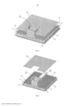
[0010] Oferecemos abaixo uma descrição detalhada das representações preferenciais, apenas de maneira ilustrativa, como referência aos seguintes desenhos, em que:A FIG. 1 é uma visualização em perspectiva de uma eclusa Inundada, de acordo com urna das representações da presente invenção;A FIG. 2 é uma vista explodida de uma eclusa inundada, de acordo com uma das representações da presente invenção;A FIG. 3 é uma visualização em perspectiva de urna eclusa submersa, de acordo com uma das representações da presente invenção;A FIG 4 é uma vista explodida de uma eclusa submersa, de acordo com uma das representações da presente invenção;A FIG. 5. é uma visualização em perspectiva de uma eclusa inundada e uma eclusa submersa, de acordo com uma das representações da presente invenção;A FIG. 6 é uma vista explodida de uma eclusa inundada e uma eclusa submersa, de acordo com uma das representações da presente invenção;A FIG., 7 é urna visualização em perspectiva do dispositivo de purificação, de acordo com uma das representações da presente invenção; A FIG., 8 é uma visualização em corte do dispositivo de purificação, de acordo com uma das representações da presente invenção;A .FIG. 9 é uma visualização transversal do dispositivo de purificação, de acordo com uma das representações da presente invenção;A FIG. 10 é uma visão de cima de uma planta de purificação de gases incorporando uma das representações do purificador da presente invenção. Nos desenhos, urna das representações da invenção é ilustrada com propósitos meramente ilustrativos. Deve-se entender expressamente que a descrição e figuras têm objetivo meramente ilustrativo e servem como urna ferramenta para facilitar a compreensão e não são fornecidas corno definição dos Emites da invenção.[0010] We offer below a detailed description of the preferred representations, for illustrative purposes only, with reference to the following drawings, in which: FIG. 1 is a perspective view of a Flooded lock in accordance with one of the embodiments of the present invention; FIG. 2 is an exploded view of a flooded lock in accordance with one of the embodiments of the present invention; FIG. 3 is a perspective view of a submerged sluice in accordance with one embodiment of the present invention; FIG. 4 is an exploded view of a submerged sluice in accordance with one embodiment of the present invention; FIG. 5. is a perspective view of a flooded lock and a submerged lock, in accordance with one of the embodiments of the present invention; FIG. 6 is an exploded view of a flooded lock and a submerged lock in accordance with one embodiment of the present invention; FIG. 7 is a perspective view of the purification device in accordance with one of the embodiments of the present invention; FIG. 8 is a sectional view of the purification device in accordance with one embodiment of the present invention; FIG. 9 is a cross-sectional view of the purification device according to one of the embodiments of the present invention; FIG. 10 is a top view of a gas scrubbing plant incorporating one of the scrubber representations of the present invention. In the drawings, one of the embodiments of the invention is illustrated for illustrative purposes only. It is expressly understood that the description and figures are for illustrative purposes only and serve as a tool to facilitate understanding and are not provided as a definition of the Issues of the invention.
[0011] O purificador da presente invenção foi projetado para ser eficiente, flexivel e expansível. Ele pode se diferenciar de outros purificadores a água devido á sua abordagem na apresentação dos gases a serem purificados e sua eclusa purificadora única. Os gases a serem purificados podem ser originários de varias fontes, incluindo gases de combustão de exaustão de motores a diesel e fornalhas a carvão, gases de processamento de fábricas de produtos químicos, celulose, papel e revestimentos, e estufas de biomassa.[0011] The purifier of the present invention is designed to be efficient, flexible and expandable. It can differentiate itself from other water purifiers due to its approach to presenting the gases to be purified and its unique purifying sluice. The gases to be purified can originate from a variety of sources, including exhaust flue gases from diesel engines and coal-fired furnaces, process gases from chemical plants, pulp, paper and coatings, and biomass ovens.
[0012] A invenção pode ser categorizada como um purificador a água, pois utiliza o liquido de purificação contido no tanque. A composição do líquido de purificação é selecionada com base na composição química do gás a ser purificado e dos poluentes e odores a serem removidos dos gases. O tamanho e tipo de tanque pode ser selecionado para otimizar a purificação com base no volume de gás a ser purificado e a configuração do espaço físico disponível para a instalação do purificador. Uma ou mais das eclusas de purificação podem ser posicionadas no liquido de purificação dentro do tanque. O gás a ser purificado é direcionado a um volume abaixo da porção mais inferior da eclusa de purificação mais inferior.[0012] The invention can be categorized as a water purifier, as it uses the purification liquid contained in the tank. The composition of the purification liquid is selected based on the chemical composition of the gas to be purified and the pollutants and odors to be removed from the gases. The size and type of tank can be selected to optimize purification based on the volume of gas to be purified and the configuration of the physical space available for installing the scrubber. One or more of the purification locks can be positioned on the purification liquid inside the tank. The gas to be purified is directed to a volume below the lowermost portion of the lowermost purification lock.
[0013] A invenção permite que as eclusas de purificação e o tanque circundante sejam redondos, quadrados, retangulares ou de qualquer outro formato conforme o espaço disponível para a instalação. É possível que os formatos retangular e quadrado sejam preferidos para otimizar a relação entre o volume de gás purificado e a área do tanque.[0013] The invention allows the purification locks and the surrounding tank to be round, square, rectangular or any other shape depending on the space available for the installation. Rectangular and square shapes may be preferred to optimize the relationship between purified gas volume and tank area.
[0014] A área horizontal de cada eclusa de purificação pode variar dependendo do tamanho do tanque e se a purificação é obtida em um tanque ou em vários. A capacidade de expansão da eclusa de purificação permite que a invenção seja formatada para ser utilizada em aplicações industriais de grande escala.[0014] The horizontal area of each purification lock can vary depending on the size of the tank and whether purification is achieved in one tank or in several. The scalability of the purification lock allows the invention to be formatted for use in large-scale industrial applications.
[0015] O gás apresentado à eclusa é normalmente originário de processos de combustão com temperaturas próximas aos 600°C. Dessa forma, o a gás a ser purificado deve ser resfriado a uma temperatura máxima de 80°C e, preferencialmente, a 50°C com o uso de trocadores de calor de vários designs anteriores à introdução do gás da invenção. O gás pode ser introduzido seco ou misturado com um liquido refrigerante.[0015] The gas presented to the lock normally originates from combustion processes with temperatures close to 600°C. Thus, the gas to be purified must be cooled to a maximum temperature of 80°C and preferably to 50°C using heat exchangers of various designs prior to the introduction of the gas of the invention. The gas can be introduced dry or mixed with a liquid refrigerant.
[0016] O purificador da presente invenção incorpora uma ou mais eclusas de purificação horizontais, expansíveis linearmente, normalmente em formato retangular. O gás a ser purificado pode ser introduzido do topo do purificador, de qualquer lado através de uma ou mais portas de entrada, ou da parte inferior do purificador. Em uma representação preferencial, o purificador 2 da presente invenção pode incorporar duas eclusas de purificação diferentes. Uma das eclusas de purificação encontra-se representada nas Figuras 1 e 2 e é chamada de eclusa submersa 4. Essa eclusa é formada por uma placa retangular 6, geralmente plana, com várias fendas estreitas 8. dispostas nela para a passagem através da eclusa dos gases. Ao longo de cada extremidade 10 da placa retangular, há uma fileira de orifícios maiores 12 para o fluxo do liquido de purificação, Uma parede sólida vertical 14 estende-se para a parte inferior da placa, paralela a cada extremidade, e afastada da extremidade da placa a uma posição interna da fileira de orifícios ao longo da extremidade da placa. As extremidades de cada parede vertical juntam-se a duas paredes verticais adjacentes para formar uma caixa, com uma extremidade inferior aberta e uma extremidade superior formada pela placa com as fendas. A eclusa submersa é a eclusa mais inferior da montagem do purificador. A placa se estende até as paredes do tanque purificador. O formato horizontal da eclusa de purificação pode variar, mas a representação preferida é retangular.[0016] The purifier of the present invention incorporates one or more horizontal purifying locks, linearly expandable, usually rectangular in shape. The gas to be purified may be introduced from the top of the scrubber, from either side through one or more inlet ports, or from the bottom of the scrubber. In a preferred embodiment, the
[0017] O outro estilo da eclusa de purificação recebe uma eclusa inundada 16, como mostram as Figuras 3 e 4. A eclusa inundada possui fendas 18 para a passagem do gás, mas não tem as fileiras de orifícios maiores ao longo de cada extremidade da placa. Não há paredes verticais se estendendo abaixo da placa. Uma ou mais eclusas inundadas podem ser colocadas acima da eclusa submersa na montagem do purificador, como mostram as Figuras 5 e 6.[0017] The other style of purification sluice receives a flooded
[0018] Como ilustram as Figuras 7 e 8, uma representação da montagem do purificador da presente invenção é formada por um tanque 20, com uma eclusa submersa 4 que se estende horizontalmente pelo tanque. O tanque é construido de maneira que possa conter o liquido de purificação sem vazar ou acarretar falhas estruturais. Acima da eclusa submersa há um primeiro defletor 22, que se estende horizontalmente pelo tanque de purificação, Acima do primeiro defletor, encontra-se a eclusa inundada 16, que se estende horizontalmente pelo tanque de purificação. O segundo defletor 24 encontra-se acima da eclusa inundada, estendendo-se horizontalmente pelo tanque de purfficação. Acima do segundo defletor e próximo ao teto do tanque de purificação, há um ou mais bicos de pulverização 26. A extremidade inferior do tanque de purificação é preferencialmente com estreitamento para direcionar o líquido de purificação em direção à saida do liquido 28. A entrada do liquido 30 encontra-se na parte superior do tanque de purificação. Na representação mostrada nas Figuras 7 e 8, a entrada de gás 32 é posicionada na parte superior do tanque de purificação e o duto de entrada de gás 34 estende-se verticalmente pelo tanque até uma câmara de distribuição de gás 36, estendendo-se de forma medial ao longo da eclusa submersa. O tubo de escoamento 38 encontra-se disposto ao longo da eclusa inundada 16 para permitir a drenagem do líquido de purificação de cima eclusa inundada para a parte inferior do tanque. Uma porta de acesso 40 esta localizada em um dos lados do tanque de purificação para permitir o acesso às eclusas e ao interior do tanque. O desumidificador 42 pode estar disposto acima do tanque de purificação para receber o gás umidíficado que deixa o purificador. A malha de apoio 44 estende-se pelo volume do desumidificador para absorver a umidade do gás. Os bicos de pulverização 46 suplementares podem ser dispostos dentro do desumidificador próximos á salda de gás 48 na parte superior do dispositivo. Corno mostra a FIG. 9, a orientação horizontal das eclusas de purificação da invenção cria uma profundidade fixa 50 do líquido de purificação 52 acima da eclusa submersa 4. Isso cria uma contrapressão constante, causada pela profundidade do liquido acirra da eclusa de purificação, independentemente do volume de gás sendo processado. Além disso, a orientação horizontal do design da eclusa de purificação ocupa 100% das fendas disponíveis na eclusa de punficação o tempo inteiro. Para a eclusa submersa, o liquido de purificação é mantido a um nível para criar urna profundidade: fixa para o liquido de purificação acima da eclusa. Enquanto que as fendas estreitas da eclusa não permite que o liquido de purificação sela drenado pela área central da eclusa submersa, devido à pressão para cima do gás sendo purificado, o excesso de liquido de purificação é capaz de passar pelas aberturas maiores ao longo das extremidades da eclusa submersa, como indica o item 54 para manter o nível desejado de líquido de purificação. Para a eclusa inundada 16, o liqüido de purificação não pode passar pelas fendas da eclusa inundada. então o liquido acumulará ao nível 56, determinado pela extremidade superior do tubo de escoamento 58. O liquido acima da extremidade superior do tubo de escoamento será drenado até a porção mais inferior do tanque de purificação, como indicado no item 60. Dessa forma, um nível geralmente constante de líquido de purificação é mantido acima da eclusa inundada.[0018] As Figures 7 and 8 illustrate, a representation of the purifier assembly of the present invention is formed by a
[0019] Quando a entrada lateral de gás do purificador é utilizada, a ausência de urre cano de entrada de gás e área de montagem torna toda a área acima das eclusas de purificação livre de restrições para maximizar a área das fendas da eclusa de purificação. A maximização da área disponível para as fendas de purificação serve para minimizar as dimensões gerais do purificador. Isso reduz o tamanho geral da Invenção e aumenta seu potencial de instalação em áreas resumidas.[0019] When the side gas inlet of the scrubber is used, the absence of a gas inlet pipe and mounting area makes the entire area above the scrubbing locks free of restrictions to maximize the area of the scrubbing lock slots. Maximizing the area available for the scrubber slots serves to minimize the overall dimensions of the scrubber. This reduces the overall size of the Invention and increases its installation potential in summarized areas.
[0020] A orientação das fendas da eclusa de purificação oferece um caminho vertical desobstruído para as bolhas formadas pelas fendas na eclusa de piírificação. A largura, o número e a orientação das fendas da eclusa de purificação criam o maior número de pequenas bolhas possível. A interação do gás e do liquido é turbulenta para urna interação mecânica e química aprimorada dos dois meios. A invenção permite que as bolhas originadas nas fendas da eclusa de purificação para preencher toda a área do tanque de purificação. Isso reduz a velocidade dos gases resultantes e cria urna turbulência generalizada quando o gás purificado deixa o liquido de purificação e entra na área de borda livre do tanque de purificação. A velocidade mais baixa maximiza a duração do contato entre o gás e o líquido de purificação. Além disso, o nível mais baixo da turbulência da superfície do liquido de purificação, em decorrência da baixa velocidade do gás resultante, é preferível aos picos de alta turbulência, criados por abordagens alternativas.[0020] The orientation of the purification sluice slits provides an unobstructed vertical path for the bubbles formed by the slits in the pyrification sluice. The width, number and orientation of the purification sluice slits create as many small bubbles as possible. The interaction of gas and liquid is turbulent for an improved mechanical and chemical interaction of the two media. The invention allows bubbles originating in the slits of the purification sluice to fill the entire area of the purification tank. This reduces the velocity of the resulting gases and creates general turbulence as the purified gas leaves the purification liquid and enters the freeboard area of the purification tank. The lower speed maximizes the duration of contact between the gas and the purification liquid. Furthermore, the lower level of surface turbulence of the purification liquid, due to the low velocity of the resulting gas, is preferable to the high turbulence peaks created by alternative approaches.
[0021] Um ou mais drenos 62 são fixos no fundo do tanque. Uma ou mais entradas estão localizadas no topo, fundo e laterais do tanque. As entradas permitem que o gás a ser purificado entre no tanque. Os dutos estão localizados em cada entrada para conduzir o gás à eclusa de purificação.[0021] One or more drains 62 are attached to the bottom of the tank. One or more inlets are located at the top, bottom and sides of the tank. The inlets allow the gas to be purified to enter the tank. Ducts are located at each inlet to lead the gas to the purification lock.
[0022] O tanque contém uma ou mais saldas no topo para coletar o fluxo de gás antes que ele deixe o tanque, As eclusas têm uma separação minima de 125mm. É preferível um tampo plano no. nível mais baixo do purificador. As eclusas superiores podem ter folgas verticais em qualquer das configurações. O topo da eclusa pode conter várias fendas com largura preferencial de 60 milésimos de polegada. As fendas podem ser em qualquer padrão, mas preferem-se as fendas lisas. O corte vertical das fendas pode ser perpendicular ou a um ângulo ao plano da placa superior, com preferência para um corte angular. O número de fendas, a área resultante delas e o tamanho da eclusa de purificaçãO são selecionados pelo volume de gás a ser purificado e o formato do espaço disponível para o purificador, :Para processar grandes Volumes de gás, a eclusa pode conter várias entradas em intervalos regulares ao longo do comprimento da eclusa de purificação.[0022] The tank contains one or more outlets at the top to collect the gas flow before it leaves the tank. The locks have a minimum separation of 125mm. Flat top no. lowest level of the purifier. Upper locks can have vertical clearances in either configuration. The top of the lock may contain several slots with a preferred width of 60 thousandths of an inch. The slits can be in any pattern, but smooth slits are preferred. The vertical cut of the slits can be perpendicular or at an angle to the plane of the top plate, with preference for an angled cut. The number of slits, their resulting area and the size of the purification lock are selected by the volume of gas to be purified and the shape of the space available for the scrubber, :To process large volumes of gas, the lock can contain several inlets in regular intervals along the length of the purification lock.
[0023] Um ou mais defletores dentro do tanque de purificação servem corno difusores de turbulência. Os defletores consistem em uma placa com várias aberturas dispostas por ela, que permite o movimento vertical do liquido de purificação, reduzindo também a influência horizontal do liquido de purificação, Vários bicos de pulverização estão localizados na extremidade superior do tanque, 'Os bicos direcionam a pulverização do líquido de purificação em direção à zona de turbulência acima da eclusa superior. Os dispositivos de purificação na forma de veios ou telas (não mostrados) podem estar localizados acima dos bicos de pulverização na região mais superior do tanque.[0023] One or more baffles within the purification tank serve as turbulence diffusers. The deflectors consist of a plate with several openings arranged through it, which allows the vertical movement of the purification liquid, also reducing the horizontal influence of the purification liquid, Several spray nozzles are located at the upper end of the tank, 'The nozzles direct the spraying the purification liquid towards the turbulence zone above the upper lock. Purification devices in the form of shafts or screens (not shown) may be located above the spray nozzles in the uppermost region of the tank.
[0024] Os gases a serem purificados pelo purificador da invenção são normalmente liberados pelo motor ou fornalha a aftas temperaturas. Portanto, antes da sua entrada na invenção, os gases são resfriados a uma temperatura de 50°C pelo trocador de calor convencional. Dependendo da escolha de trocador de calor a ser empregado, o gás resfriado pode ou não conter líquido refrigerante como componente do fluxo.[0024] The gases to be purified by the purifier of the invention are normally released by the engine or furnace at high temperatures. Therefore, before entering the invention, the gases are cooled to a temperature of 50°C by the conventional heat exchanger. Depending on the choice of heat exchanger to be used, the cooled gas may or may not contain liquid refrigerant as a component of the flow.
[0025] O tanque de purificação é preenchido com líquido de purificação a um nível ideal de 150mm acima do topo da eclusa de purificação submersa. O dispositivo de monitoramento do. líquido de purificação mantém o nível ideal do liquido. O gás a ser purificado é introduzido no dispositivo de purificação através de uma porta de entrada localizada na lateral, fundo ou topo do tanque de purificação. O sensor de temperatura e pressão pode estar localizado neste ponto para monitorar as condições da entrada.Em uma das representações, o gás é transportado pelo duto de entrada a uma porta de entrada localizada na eclusa submersa para permitir a dispersão uniforme do gás ao longo da posição medial do lado inferior da eclusa submersa.O gás é limitado pelas paredes da eclusa submersa e direcionado através das fendas da placa. O gás contido é liberado pelas fendas na eclusa submersa, criando uma zona de bolhas altamente agitadas acima da eclusa perfurada. Em um caso ideal, as fendas da eclusa inferior são cortadas a um ângulo de 30 graus na vertical, de forma a criar um fluxo anti-horário de mistura de gás turbulenta acima da eclusa. O gás então entra em contato com o defletor localizado imediatamente após deixar a eclusa submersa. O difusor é formatado para desviar o gás de forma a permitir a formação de uma mistura uniforme e estável de gás e liquido acima da eclusa.[0025] The purification tank is filled with purification liquid at an optimal level of 150mm above the top of the submerged purification lock. The monitoring device. Purifying liquid maintains optimal liquid level. The gas to be purified is introduced into the purification device through an inlet port located on the side, bottom or top of the purification tank. The temperature and pressure sensor can be located at this point to monitor the conditions of the inlet. In one of the representations, the gas is transported through the inlet duct to an inlet port located in the submerged lock to allow uniform dispersion of the gas along the entrance. medial position of the underside of the submerged lock. The gas is limited by the walls of the submerged lock and directed through the slots in the plate. The contained gas is released through the cracks in the submerged lock, creating a zone of highly agitated bubbles above the perforated lock. In an ideal case, the slits of the lower sluice are cut at a 30 degree angle from the vertical so as to create a counterclockwise flow of turbulent gas mixture above the sluice. The gas then contacts the deflector located immediately after leaving the lock submerged. The diffuser is shaped to deflect the gas to allow a uniform and stable mixture of gas and liquid to form above the lock.
[0026] A mistura gás/líquido eleva-se acima da primeira eclusa e fica contida abaixo da eclusa inundada. A área de superfície maior da segunda eclusa permite uma área maior para as fendas, que é utilizada para reduzir a velocidade do gás que passa pelas fendas da eclusa inundada. Preferencialmente, as fendas na eclusa inundada são cortadas a um ângulo de aproximadamente 30 graus na vertical, de forma a causar uma circulação em sentido horário na zona de turbulência acima da eclusa de purificação. A zona de turbulência acima da eclusa inundada contém um segundo defletor para limitar o estirão turbulento do liquido de purificação em uma área livre maior. O gás purificado está agora livre para elevar-se lentamente no tanque de purificação. O gás que se eleva recebe a pulverização de líquido de purificação de vários bicos de pulverização.[0026] The gas/liquid mixture rises above the first lock and is contained below the flooded lock. The larger surface area of the second lock allows for a larger area for the sluices, which is used to reduce the velocity of gas passing through the slits of the flooded sluice. Preferably, the slits in the flooded lock are cut at an angle of approximately 30 degrees to the vertical so as to cause clockwise circulation in the turbulence zone above the purification lock. The turbulence zone above the flooded lock contains a second baffle to limit the turbulent surge of purification liquid over a larger free area. The purified gas is now free to slowly rise in the purification tank. The rising gas receives the spray of purification liquid from several spray nozzles.
[0027] Elevando-se acima das cabeças de pulverização, o gás mantém-se á temperatura de entrada de 50°C, com 100% de umidade relativa. Além disso, a água livre resultante da mistura de turbulência na eclusa de purificação é transportada junto com o gás que se eleva. A água livre é removida conforme o gás passa pelo desumidificador contendo uma malha de apoio absorvente na região superior do purificador. O gás pode entrar em uma coluna de exaustão de determinado tamanho para anter o fluxo a um ritmo aproximadamente 50% mais lento do que a sua velocidade de entrada. O gás de saída resfriado é direcionado para um trocador de calor onde interage com o ar quente da fonte geradora de gás. O gás reaquecido sai do trocador de calor e é liberado para o ar ambiente.[0027] Rising above the spray heads, the gas is maintained at an inlet temperature of 50°C, with 100% relative humidity. In addition, the free water resulting from the turbulence mixture in the purification sluice is transported along with the rising gas. Free water is removed as the gas passes through the dehumidifier containing an absorbent backing mesh in the upper region of the purifier. Gas can enter an exhaust column of a given size to stop the flow at a rate approximately 50% slower than its inlet velocity. The cooled output gas is directed to a heat exchanger where it interacts with hot air from the gas generating source. The reheated gas leaves the heat exchanger and is released into the ambient air.
[0028] O líquido de purificação é constantemente circulado dentro de um sistema fechado. O líquido é liberado através de um dreno no fundo do tanque e entra em uma bomba de circulação. Na saída da bomba, a temperatura e o pH do liquido são monitorados até um ou mais dispositivos de filtragem para remover partículas e sais precipitados de enxofre, carbono e outros elementos. Após o processo de filtragem, o liquido entra no trocador de calor onde é resfriado. O fluxo líquido pode ser dividido na saída do trocador de calor com o bruto do fluxo indo para o trocador de calor do gás entrante e o restante direcionado às cabeças de pulverização dentro do tanque de purificação. O nível do fluxo é mantido de forma que o liquido de purificação possa ser processado uma vez por minuto, em uma representação ideal. Uma representação da montagem da usina incluindo o purificador da presente invenção pode ser vista na Figura 10.[0028] The purification liquid is constantly circulated within a closed system. The liquid is released through a drain at the bottom of the tank and enters a circulation pump. At the pump outlet, the temperature and pH of the liquid are monitored through one or more filter devices to remove particles and precipitated salts of sulfur, carbon and other elements. After the filtering process, the liquid enters the heat exchanger where it is cooled. The liquid flow can be split at the outlet of the heat exchanger with the bulk of the flow going to the incoming gas heat exchanger and the remainder directed to the spray heads inside the purification tank. The flow level is maintained so that the purification liquid can be processed once per minute, in an ideal representation. A representation of the plant assembly including the purifier of the present invention can be seen in Figure 10.
[0029] Para purificar o dióxido de enxofre, o líquido de purificação consiste em uma solução de cal, que é armazenada em um tanque isolado. O tanque de armazenagem possui uma bomba de circulação para misturar a cal constantemente à solução. Uma bomba separada alimenta o líquido de purificação no sistema purificador, como necessário para manter a quantidade e o pH do liquido operacionais. Pode ser adicionada a cal em pó manualmente ou através de uma rosca de passador, dependendo das condições operacionais. Para purificar os óxidos de nitrogênio, a amônia pode ser utilizada como líquido de purificação. Outros materiais podem ser utilizados para remover o dióxido de carbono ou outros contaminantes do gás a ser purificado.[0029] To purify sulfur dioxide, the purification liquid consists of a lime solution, which is stored in an insulated tank. The storage tank has a circulation pump to constantly mix the lime into the solution. A separate pump feeds purification liquid into the scrubber system as needed to maintain operational liquid quantity and pH. Powdered lime can be added manually or through a dowel screw, depending on operating conditions. To purify nitrogen oxides, ammonia can be used as a purification liquid. Other materials may be used to remove carbon dioxide or other contaminants from the gas to be purified.
[0030] Levando em conta o supracitado, veremos que esta invenção tem boa adaptação para satisfazer diferentes necessidades e objetivos aqui dispostos, além de oferecer outras vantagens que são óbvias e inerentes ao parato. Entende-se que algumas funcionalidades e subcombinações são úteis e podem ser empregadas com relação a outras funcionalidades e subcombinações. Elas estão incluídas no escopo das reivindicações, Podem ser compostas muitas representações da invenção sem fugir do escopo das reivindicações. Deve-se entender que todas as questões mostradas aqui ou nas figuras anexadas devem ser interpretadas como meramente ilustrativas e não de maneira restritiva. Os especialistas na matéria podem se beneficiar do fato de que outras variações da representação ideal podem ser praticadas sem fugir do escopo da invenção.[0030] Taking into account the above, we will see that this invention is well adapted to satisfy different needs and objectives set forth herein, in addition to offering other advantages that are obvious and inherent to the parato. It is understood that some features and sub-combinations are useful and can be employed in relation to other features and sub-combinations. They are included in the scope of the claims. Many representations of the invention can be composed without departing from the scope of the claims. It should be understood that all questions shown here or in the attached figures are to be interpreted as illustrative only and not in a restrictive manner. Those skilled in the art can benefit from the fact that other variations of the ideal representation can be practiced without departing from the scope of the invention.
Claims (12)
Applications Claiming Priority (2)
| Application Number | Priority Date | Filing Date | Title |
|---|---|---|---|
| US22035209P | 2009-06-25 | 2009-06-25 | |
| PCT/CA2010/000988 WO2010148513A1 (en) | 2009-06-25 | 2010-06-25 | Improved gas scrubber apparatus and method |
Publications (2)
| Publication Number | Publication Date |
|---|---|
| BRPI1016074A2 BRPI1016074A2 (en) | 2021-04-13 |
| BRPI1016074B1 true BRPI1016074B1 (en) | 2022-02-15 |
Family
ID=43385837
Family Applications (1)
| Application Number | Title | Priority Date | Filing Date |
|---|---|---|---|
| BRPI1016074-4A BRPI1016074B1 (en) | 2009-06-25 | 2010-06-25 | IMPROVED GAS PURIFICATION DEVICE |
Country Status (26)
| Country | Link |
|---|---|
| US (1) | US8940079B2 (en) |
| EP (1) | EP2509701B1 (en) |
| JP (1) | JP5631985B2 (en) |
| KR (1) | KR101742834B1 (en) |
| CN (1) | CN102497918B (en) |
| AU (1) | AU2010265768A1 (en) |
| BR (1) | BRPI1016074B1 (en) |
| CA (1) | CA2798881C (en) |
| CL (1) | CL2011003303A1 (en) |
| CO (1) | CO6491064A2 (en) |
| CR (1) | CR20120046A (en) |
| CU (1) | CU20110242A7 (en) |
| DO (1) | DOP2011000401A (en) |
| EA (1) | EA021020B1 (en) |
| IL (1) | IL217126A0 (en) |
| MA (1) | MA33456B1 (en) |
| MX (1) | MX2012000085A (en) |
| MY (1) | MY160053A (en) |
| NI (1) | NI201100225A (en) |
| NZ (1) | NZ597780A (en) |
| PE (2) | PE20131242A1 (en) |
| SG (1) | SG176980A1 (en) |
| TN (1) | TN2011000665A1 (en) |
| UA (1) | UA110014C2 (en) |
| WO (1) | WO2010148513A1 (en) |
| ZA (1) | ZA201200629B (en) |
Families Citing this family (20)
| Publication number | Priority date | Publication date | Assignee | Title |
|---|---|---|---|---|
| ITMI20131514A1 (en) * | 2013-09-12 | 2015-03-13 | Innovation In Sciences & Technologi Es S R L | METHOD AND SYSTEM FOR FLUID STREAM CHEMICAL COMPOUNDS COLLECTION, DEPOSITION AND SEPARATION |
| CN105879519A (en) * | 2015-01-20 | 2016-08-24 | 张毅 | Immersive washing air purification device |
| CR20170606A (en) * | 2015-06-02 | 2018-08-10 | Pacific Green Technologies Inc | MULTI-LEVEL GAS TREATMENTER WITH MULTIPLE FLOODED CLEANING HEADS |
| JP6749146B2 (en) * | 2015-11-27 | 2020-09-02 | 株式会社ネイブヒート | Wet gaseous substance treatment equipment |
| US11752465B2 (en) | 2016-11-09 | 2023-09-12 | Schubert Environmental Equipment, Inc. | Wet scrubber apparatus |
| JP2020500701A (en) | 2016-12-01 | 2020-01-16 | エンビロ アンビエント コーポレーション | Apparatus and method for capturing carbon dioxide |
| JP6104491B1 (en) | 2017-01-20 | 2017-03-29 | 三菱日立パワーシステムズ株式会社 | Ship desulfurization apparatus and ship equipped with the ship desulfurization apparatus |
| GB2561848A (en) * | 2017-04-24 | 2018-10-31 | Manik Ventures Ltd | Waste disposal apparatus |
| GB2563621A (en) * | 2017-06-20 | 2018-12-26 | Manik Ventures Ltd | Waste disposal apparatus |
| TWI614057B (en) * | 2017-06-20 | 2018-02-11 | 友達光電股份有限公司 | Gas purifier |
| IT201800006334A1 (en) * | 2018-06-14 | 2019-12-14 | Filter for fluids in the gaseous state and vehicle comprising this filter | |
| KR200490847Y1 (en) * | 2018-06-19 | 2020-01-13 | 아틱스엔지니어링(주) | Rectangular-pillar-type scrubber for purifying exhaust gas of a vessel |
| US10687410B2 (en) * | 2018-07-27 | 2020-06-16 | Taiwan Semiconductor Manufacturing Co., Ltd. | Extreme ultraviolet radiation source and cleaning method thereof |
| FI128920B (en) * | 2018-11-16 | 2021-03-15 | Valmet Technologies Oy | A scrubber for scrubbing exhaust gas of a combustion engine of a ship, a method for adapting an old scrubber, and a method for maintaining a scrubber |
| KR20210023498A (en) * | 2019-08-23 | 2021-03-04 | 엘지전자 주식회사 | Desulfurizer |
| RU2724780C1 (en) * | 2019-12-12 | 2020-06-25 | Мороз Максим Николаевич | Device for wet cleaning of gases |
| CN112387051A (en) * | 2020-11-13 | 2021-02-23 | 阔创实业(上海)有限公司 | Gas washing device capable of realizing high cleanliness gas |
| KR102374527B1 (en) * | 2021-07-23 | 2022-03-16 | 주식회사 삼원카본써큘레이션 | Flue Gas Treatment Device Using Flooding in Scrubber Equipped with Packing |
| KR102374520B1 (en) * | 2021-07-23 | 2022-03-17 | 주식회사 삼원카본써큘레이션 | Combustion System Including Energy-Saving Flue Gas Treatment Facility |
| CN115854737B (en) * | 2022-12-08 | 2023-07-21 | 湖南科技大学 | Method for determining redundancy critical height of overflow plate of water bath heat exchanger |
Family Cites Families (15)
| Publication number | Priority date | Publication date | Assignee | Title |
|---|---|---|---|---|
| BE579015A (en) * | 1958-05-31 | |||
| DE1442779A1 (en) * | 1963-11-07 | 1970-03-26 | Julius Montz Fa | Exchange column |
| GB1333877A (en) * | 1971-02-12 | 1973-10-17 | Hughes Co Ltd F A | Gas scrubber |
| US3739555A (en) * | 1971-12-30 | 1973-06-19 | Combustion Eng | Modular air pollution control scrubber bed |
| US3855368A (en) * | 1972-04-26 | 1974-12-17 | Ceskoslovenska Akademie Ved | Apparatus for bringing fluid phases into mutual contact |
| JPS6412625U (en) * | 1987-07-15 | 1989-01-23 | ||
| US5298228A (en) * | 1992-09-08 | 1994-03-29 | Atlantic Richfield Company | Method and apparatus for treating hydrocarbon gas streams contaminated with carbonyl sulfide |
| US5478507A (en) * | 1994-02-16 | 1995-12-26 | Carbonair, Inc. | Gas-liquid contacting apparatus with valved downcomer |
| JP2715059B2 (en) * | 1994-05-06 | 1998-02-16 | 韓国電力公社 | Method and apparatus for flue gas and desulfurization |
| US5512072A (en) * | 1994-12-05 | 1996-04-30 | General Electric Environmental Services, Inc. | Flue gas scrubbing apparatus |
| DK0742039T3 (en) * | 1995-05-08 | 1999-09-13 | Thermoselect Ag | Device for purifying gases, such as exhaust gases and / or synthesis gases |
| US6322756B1 (en) * | 1996-12-31 | 2001-11-27 | Advanced Technology And Materials, Inc. | Effluent gas stream treatment system having utility for oxidation treatment of semiconductor manufacturing effluent gases |
| CN2443789Y (en) * | 2000-10-17 | 2001-08-22 | 中国石化集团金陵石油化工有限责任公司 | Dynamic wave washing device |
| US6783120B2 (en) * | 2001-10-09 | 2004-08-31 | Uop Llc | Multiple downcomer fractional distillation tray and process |
| WO2010076853A1 (en) | 2008-12-30 | 2010-07-08 | Uehara Kyomasa | Method for dust removal and cleaning of polluted gas by water washing |
-
2010
- 2010-06-25 MY MYPI2011006251A patent/MY160053A/en unknown
- 2010-06-25 WO PCT/CA2010/000988 patent/WO2010148513A1/en active Application Filing
- 2010-06-25 CN CN201080037844.3A patent/CN102497918B/en active Active
- 2010-06-25 EP EP10791121.6A patent/EP2509701B1/en active Active
- 2010-06-25 PE PE2013000522A patent/PE20131242A1/en active IP Right Grant
- 2010-06-25 MX MX2012000085A patent/MX2012000085A/en not_active Application Discontinuation
- 2010-06-25 AU AU2010265768A patent/AU2010265768A1/en not_active Abandoned
- 2010-06-25 KR KR1020127001887A patent/KR101742834B1/en active IP Right Grant
- 2010-06-25 CA CA2798881A patent/CA2798881C/en active Active
- 2010-06-25 MA MA34567A patent/MA33456B1/en unknown
- 2010-06-25 JP JP2012516453A patent/JP5631985B2/en active Active
- 2010-06-25 BR BRPI1016074-4A patent/BRPI1016074B1/en active IP Right Grant
- 2010-06-25 NZ NZ597780A patent/NZ597780A/en unknown
- 2010-06-25 EA EA201270072A patent/EA021020B1/en active IP Right Revival
- 2010-06-25 UA UAA201200781A patent/UA110014C2/en unknown
- 2010-06-25 PE PE2011002170A patent/PE20120922A1/en not_active Application Discontinuation
- 2010-06-25 SG SG2011095841A patent/SG176980A1/en unknown
- 2010-06-25 US US13/380,449 patent/US8940079B2/en active Active
-
2011
- 2011-12-21 IL IL217126A patent/IL217126A0/en unknown
- 2011-12-22 NI NI201100225A patent/NI201100225A/en unknown
- 2011-12-22 DO DO2011000401A patent/DOP2011000401A/en unknown
- 2011-12-23 TN TNP2011000665A patent/TN2011000665A1/en unknown
- 2011-12-26 CU CU20110242A patent/CU20110242A7/en unknown
- 2011-12-26 CL CL2011003303A patent/CL2011003303A1/en unknown
-
2012
- 2012-01-20 CO CO12008050A patent/CO6491064A2/en active IP Right Grant
- 2012-01-24 CR CR20120046A patent/CR20120046A/en unknown
- 2012-01-25 ZA ZA2012/00629A patent/ZA201200629B/en unknown
Also Published As
Similar Documents
| Publication | Publication Date | Title |
|---|---|---|
| BRPI1016074B1 (en) | IMPROVED GAS PURIFICATION DEVICE | |
| ES2833049T3 (en) | Multi-level gas scrubber with multiple flooded scrubber heads | |
| KR20160049782A (en) | Scrubber | |
| KR101401992B1 (en) | Scrubber with multi-filtering system | |
| KR20150070110A (en) | A flue gas purification device | |
| KR20230151613A (en) | Wet purifier of harmful exhaust gas with rotary filtration filter | |
| KR20230119342A (en) | Hazardous exhaust gas wet purification device with filtration rotary filter | |
| CN200942331Y (en) | Flue gas denitrification device | |
| RU102900U1 (en) | GAS CLEANING PLANT | |
| CN207102344U (en) | A kind of flue gas desulfurization and denitrification equipment line | |
| KR102589114B1 (en) | Hazardous Exhaust Gas Wet Purification device | |
| KR200474631Y1 (en) | Complex treating system of contaminated soil | |
| KR102520796B1 (en) | Internal Gas Treatment System in Composting Facility | |
| CN207221673U (en) | A kind of high effective flue gas cleaning equipment | |
| JP2013116235A (en) | Air cleaning unit and cooling system | |
| CN106512693A (en) | Desulfurizer forced flow mixing device capable of efficient desulfurization and flue gas wet purification | |
| KR20200133503A (en) | Air and water purifier | |
| PL228299B1 (en) | Device for complex dedusting and scrubbing of gases originating from combustion of different energy carriers in heating installations | |
| KR101422760B1 (en) | Apparatus and method for removing sulfur compounds in flue gases using the sea water | |
| CN115164225A (en) | Equipment for recovering flue gas moisture | |
| OA18500A (en) | Multi-level gas scrubber with multiple flooded scrubber heads. | |
| CN102085449A (en) | Desulfurizing and dedusting device |
Legal Events
| Date | Code | Title | Description |
|---|---|---|---|
| B15I | Others concerning applications: loss of priority |
Free format text: NAO FORAM APRESENTADOS E NAO FORAM DISPONIBILIZADOS NA BIBLIOTECA DIGITAL DA OMPI OS DOCUMENTOS DA PRIORIDADE US 61/220,352 DE 25.06.2009 OU DOCUMENTOS EQUIVALENTES, CONFORME AS DISPOSICOES PREVISTAS NA LEI 9.279 DE 14/05/1996 (LPI) ART. 16 4O, ITEM 24 DO ATO NORMATIVO 128/1997 E NO ART. 26 DA RESOLUCAO INPI-PR 77/2013, MOTIVO PELO QUAL SERA DADA PERDA DE PRIORIDADE. |
|
| B06F | Objections, documents and/or translations needed after an examination request according [chapter 6.6 patent gazette] | ||
| B06U | Preliminary requirement: requests with searches performed by other patent offices: procedure suspended [chapter 6.21 patent gazette] | ||
| B12F | Other appeals [chapter 12.6 patent gazette] |
Free format text: RECURSO: 870210054614 - 17/06/2021 |
|
| B06A | Patent application procedure suspended [chapter 6.1 patent gazette] | ||
| B09A | Decision: intention to grant [chapter 9.1 patent gazette] | ||
| B16A | Patent or certificate of addition of invention granted [chapter 16.1 patent gazette] |
Free format text: PRAZO DE VALIDADE: 20 (VINTE) ANOS CONTADOS A PARTIR DE 25/06/2010, OBSERVADAS AS CONDICOES LEGAIS. PATENTE CONCEDIDA CONFORME ADI 5.529/DF, QUE DETERMINA A ALTERACAO DO PRAZO DE CONCESSAO. |