BRPI1010988B1 - "catheter pump" - Google Patents
"catheter pump" Download PDFInfo
- Publication number
- BRPI1010988B1 BRPI1010988B1 BRPI1010988-9A BRPI1010988A BRPI1010988B1 BR PI1010988 B1 BRPI1010988 B1 BR PI1010988B1 BR PI1010988 A BRPI1010988 A BR PI1010988A BR PI1010988 B1 BRPI1010988 B1 BR PI1010988B1
- Authority
- BR
- Brazil
- Prior art keywords
- drive
- catheter
- cage
- aortic valve
- pump
- Prior art date
Links
Images


Classifications
-
- A—HUMAN NECESSITIES
- A61—MEDICAL OR VETERINARY SCIENCE; HYGIENE
- A61M—DEVICES FOR INTRODUCING MEDIA INTO, OR ONTO, THE BODY; DEVICES FOR TRANSDUCING BODY MEDIA OR FOR TAKING MEDIA FROM THE BODY; DEVICES FOR PRODUCING OR ENDING SLEEP OR STUPOR
- A61M60/00—Blood pumps; Devices for mechanical circulatory actuation; Balloon pumps for circulatory assistance
- A61M60/40—Details relating to driving
- A61M60/403—Details relating to driving for non-positive displacement blood pumps
- A61M60/408—Details relating to driving for non-positive displacement blood pumps the force acting on the blood contacting member being mechanical, e.g. transmitted by a shaft or cable
- A61M60/411—Details relating to driving for non-positive displacement blood pumps the force acting on the blood contacting member being mechanical, e.g. transmitted by a shaft or cable generated by an electromotor
- A61M60/414—Details relating to driving for non-positive displacement blood pumps the force acting on the blood contacting member being mechanical, e.g. transmitted by a shaft or cable generated by an electromotor transmitted by a rotating cable, e.g. for blood pumps mounted on a catheter
-
- A—HUMAN NECESSITIES
- A61—MEDICAL OR VETERINARY SCIENCE; HYGIENE
- A61M—DEVICES FOR INTRODUCING MEDIA INTO, OR ONTO, THE BODY; DEVICES FOR TRANSDUCING BODY MEDIA OR FOR TAKING MEDIA FROM THE BODY; DEVICES FOR PRODUCING OR ENDING SLEEP OR STUPOR
- A61M60/00—Blood pumps; Devices for mechanical circulatory actuation; Balloon pumps for circulatory assistance
- A61M60/10—Location thereof with respect to the patient's body
- A61M60/122—Implantable pumps or pumping devices, i.e. the blood being pumped inside the patient's body
- A61M60/126—Implantable pumps or pumping devices, i.e. the blood being pumped inside the patient's body implantable via, into, inside, in line, branching on, or around a blood vessel
- A61M60/13—Implantable pumps or pumping devices, i.e. the blood being pumped inside the patient's body implantable via, into, inside, in line, branching on, or around a blood vessel by means of a catheter allowing explantation, e.g. catheter pumps temporarily introduced via the vascular system
-
- A—HUMAN NECESSITIES
- A61—MEDICAL OR VETERINARY SCIENCE; HYGIENE
- A61M—DEVICES FOR INTRODUCING MEDIA INTO, OR ONTO, THE BODY; DEVICES FOR TRANSDUCING BODY MEDIA OR FOR TAKING MEDIA FROM THE BODY; DEVICES FOR PRODUCING OR ENDING SLEEP OR STUPOR
- A61M60/00—Blood pumps; Devices for mechanical circulatory actuation; Balloon pumps for circulatory assistance
- A61M60/20—Type thereof
- A61M60/205—Non-positive displacement blood pumps
- A61M60/216—Non-positive displacement blood pumps including a rotating member acting on the blood, e.g. impeller
-
- A—HUMAN NECESSITIES
- A61—MEDICAL OR VETERINARY SCIENCE; HYGIENE
- A61M—DEVICES FOR INTRODUCING MEDIA INTO, OR ONTO, THE BODY; DEVICES FOR TRANSDUCING BODY MEDIA OR FOR TAKING MEDIA FROM THE BODY; DEVICES FOR PRODUCING OR ENDING SLEEP OR STUPOR
- A61M60/00—Blood pumps; Devices for mechanical circulatory actuation; Balloon pumps for circulatory assistance
- A61M60/50—Details relating to control
- A61M60/585—User interfaces
-
- A—HUMAN NECESSITIES
- A61—MEDICAL OR VETERINARY SCIENCE; HYGIENE
- A61M—DEVICES FOR INTRODUCING MEDIA INTO, OR ONTO, THE BODY; DEVICES FOR TRANSDUCING BODY MEDIA OR FOR TAKING MEDIA FROM THE BODY; DEVICES FOR PRODUCING OR ENDING SLEEP OR STUPOR
- A61M60/00—Blood pumps; Devices for mechanical circulatory actuation; Balloon pumps for circulatory assistance
- A61M60/80—Constructional details other than related to driving
- A61M60/802—Constructional details other than related to driving of non-positive displacement blood pumps
- A61M60/804—Impellers
- A61M60/806—Vanes or blades
- A61M60/808—Vanes or blades specially adapted for deformable impellers, e.g. expandable impellers
-
- A—HUMAN NECESSITIES
- A61—MEDICAL OR VETERINARY SCIENCE; HYGIENE
- A61M—DEVICES FOR INTRODUCING MEDIA INTO, OR ONTO, THE BODY; DEVICES FOR TRANSDUCING BODY MEDIA OR FOR TAKING MEDIA FROM THE BODY; DEVICES FOR PRODUCING OR ENDING SLEEP OR STUPOR
- A61M60/00—Blood pumps; Devices for mechanical circulatory actuation; Balloon pumps for circulatory assistance
- A61M60/80—Constructional details other than related to driving
- A61M60/855—Constructional details other than related to driving of implantable pumps or pumping devices
- A61M60/861—Connections or anchorings for connecting or anchoring pumps or pumping devices to parts of the patient's body
-
- A—HUMAN NECESSITIES
- A61—MEDICAL OR VETERINARY SCIENCE; HYGIENE
- A61M—DEVICES FOR INTRODUCING MEDIA INTO, OR ONTO, THE BODY; DEVICES FOR TRANSDUCING BODY MEDIA OR FOR TAKING MEDIA FROM THE BODY; DEVICES FOR PRODUCING OR ENDING SLEEP OR STUPOR
- A61M25/00—Catheters; Hollow probes
- A61M25/01—Introducing, guiding, advancing, emplacing or holding catheters
- A61M25/02—Holding devices, e.g. on the body
- A61M25/04—Holding devices, e.g. on the body in the body, e.g. expansible
-
- A—HUMAN NECESSITIES
- A61—MEDICAL OR VETERINARY SCIENCE; HYGIENE
- A61M—DEVICES FOR INTRODUCING MEDIA INTO, OR ONTO, THE BODY; DEVICES FOR TRANSDUCING BODY MEDIA OR FOR TAKING MEDIA FROM THE BODY; DEVICES FOR PRODUCING OR ENDING SLEEP OR STUPOR
- A61M60/00—Blood pumps; Devices for mechanical circulatory actuation; Balloon pumps for circulatory assistance
- A61M60/10—Location thereof with respect to the patient's body
- A61M60/122—Implantable pumps or pumping devices, i.e. the blood being pumped inside the patient's body
- A61M60/126—Implantable pumps or pumping devices, i.e. the blood being pumped inside the patient's body implantable via, into, inside, in line, branching on, or around a blood vessel
- A61M60/148—Implantable pumps or pumping devices, i.e. the blood being pumped inside the patient's body implantable via, into, inside, in line, branching on, or around a blood vessel in line with a blood vessel using resection or like techniques, e.g. permanent endovascular heart assist devices
Abstract
BOMBA DE CATETER A presente invenção refere-se a uma bomba de cateter a ser posicionada na aorta ascendente (11) próximo da válvula aórtica (10) de um ser humano sendo, compreendendo uma manga alongada 6 com um cabo de acionamento (5) se estendendo através da manga e conectável em sua extremidade proximal a uma fonte de acionamento externa e um rotor de acionamento próximo da extremidade distal do cabo de acionamento (5) montado em um eixo de acionamento (4) sendo conectado com o cabo de acionamento (5), em que o rotor de acionamento consiste de um propulsor (3) sendo embutido em uma gaiola (2) e em que o propulsor (3) e a gaiola (2) são dobráveis a partir de uma posição de inserção próxima ao eixo de acionamento (4) a uma posição de trabalho expandida, caracterizada por meios (7, 7a, 2a, 19) para ancorar o rotor de acionamento (3) na aorta ascendente (11) próximo da válvula aórtica (10) após inserção. A presente invenção também refere-se a um método para posicionar os meios de bombeamento da bomba de cateter na aorta ascendente (11) logo acima da válvula aórtica (10).CATHETER PUMP The present invention relates to a catheter pump to be positioned in the ascending aorta (11) close to the aortic valve (10) of a human being, comprising an elongated sleeve 6 with an actuation cable (5) if extending through the sleeve and connectable at its proximal end to an external drive source and a drive rotor near the distal end of the drive cable (5) mounted on a drive shaft (4) being connected with the drive cable (5 ), where the drive rotor consists of a thruster (3) being embedded in a cage (2) and where the thruster (3) and cage (2) are foldable from an insertion position close to the axis of drive (4) to an expanded working position, characterized by means (7, 7a, 2a, 19) to anchor the drive rotor (3) in the ascending aorta (11) close to the aortic valve (10) after insertion. The present invention also relates to a method for positioning the catheter pump pumping means in the ascending aorta (11) just above the aortic valve (10).
Description
[0001] "O sistema de bomba de cateter de Reitan" é a sistema de suporte circulatório temporário com base em o conceito de um propulsor dobrável na ponta de um cateter flexível. O sistema é usado em pacientes com insuficiência cardíaca quando o coração natural é incapaz de suportar o corpo com suficiente sangue oxigenado.[0001] "The Reitan catheter pump system" is a temporary circulatory support system based on the concept of a foldable propellant at the tip of a flexible catheter. The system is used in heart failure patients when the natural heart is unable to support the body with sufficient oxygenated blood.
[0002] O sistema é descrito na patente Europeia EP 0768900 e nos pedidos de patentes Suecas 0801459-9 e 0801460-7 e no a seguir junto com os últimos aprimoramentos do sistema. Os conteúdos das referidas publicações são incluídos como uma parte do presente pedido. As dimensões mencionadas são dimensões preferidas e não pre-tendem restringir a proteção reivindicada para a presente invenção.[0002] The system is described in European patent EP 0768900 and in Swedish patent applications 0801459-9 and 0801460-7 and the following together with the latest system improvements. The contents of these publications are included as part of this application. The dimensions mentioned are preferred dimensions and are not intended to restrict the protection claimed for the present invention.
[0003] Há diversas bombas de sangue no mercado, mas a maior parte delas requer grande cirurgia para ser implantada. O uso de um propulsor dobrável tem, entretanto, a vantagem de que enquanto dobrado durante a inserção se torna possível se introduzir um grande propulsor com capacidade de alto fluxo dentro do corpo percutanea- mente e sem a necessidade de cirurgia. Após implantação a bomba tem um grande propulsor durante operação. O propulsor é disposto em a cabeça de bomba na extremidade distal do cateter. Em adição ao propulsor a cabeça de bomba também consiste de uma gaiola produzida de filamentos circundando o propulsor de modo a proteger a aorta contra o propulsor.[0003] There are several blood pumps on the market, but most of them require major surgery to be implanted. The use of a foldable propellant, however, has the advantage that while folded during insertion, it is possible to introduce a large propellant with high flow capacity into the body percutaneously and without the need for surgery. After implantation, the pump has a large propellant during operation. The propellant is disposed in the pump head at the distal end of the catheter. In addition to the thruster, the pump head also consists of a cage made of filaments surrounding the thruster in order to protect the aorta against the thruster.
[0004] A inserção da bomba é realizada através de uma punção no sistema arterial, preferivelmente na artéria femoral na virilha através de uma bainha de introdução. Em uma versão anterior a bomba é avançada para dentro da aorta torácica superior com a cabeça de bomba disposto aproximadamente 5 a 10 centímetros abaixo da artéria subclávia esquerda. Uma vez em posição, o propulsor e sua gaiola de proteção são posicionados por meio de um mecanismo em forma de guarda-chuva na extremidade proximal do cateter flexível. Na referida posição a rotação do propulsor cria um gradiente de pressão dentro da aorta. A redução da pressão sanguínea criada na parte superior da aorta facilita a ejeção do ventrículo esquerdo. A maior pressão na parte inferior da aorta facilita a perfusão dos órgãos internos, especialmente os rins.[0004] The pump is inserted through a puncture in the arterial system, preferably in the femoral artery in the groin through an introduction sheath. In an earlier version, the pump is advanced into the upper thoracic aorta with the pump head approximately 5 to 10 centimeters below the left subclavian artery. Once in position, the propellant and its protective cage are positioned using an umbrella-shaped mechanism at the proximal end of the flexible catheter. In that position the rotation of the propellant creates a pressure gradient inside the aorta. The reduction in blood pressure created in the upper part of the aorta facilitates the ejection of the left ventricle. The increased pressure in the lower part of the aorta facilitates the perfusion of Organs internal organs, especially the kidneys.
[0005] A transmissão de energia ao propulsor é realizada via um fio giratório na parte interna do cateter que é conectada a um motor DC na extremidade proximal. A velocidade rotacional do motor DC pode ser ajustada e é monitorada por um console especialmente projetado.[0005] The transmission of energy to the propellant is performed via a rotating wire on the inside of the catheter that is connected to a DC motor at the proximal end. The rotational speed of the DC motor can be adjusted and is monitored by a specially designed console.
[0006] "O sistema de bomba de cateter CARDIOBRIDGE REITAN" consiste de quatro componentes principais: 1. o cateter - cabeça de bomba, 2. a unidade de acionamento, 3. o console, e 4. o conjunto superior.[0006] "The CARDIOBRIDGE REITAN catheter pump system" consists of four main components: 1. the catheter - pump head, 2. the drive unit, 3. the console, and 4. the upper assembly.
[0007] A Bomba de cateter REITAN em si consiste de um cateter interno e um externo flexível, que deslizam um contra o outro para posicionar a gaiola de proteção e desdobrar o propulsor dentro da gaiola. Há um fio de acionamento flexível percorrendo através da luz central do cateter interno. O cateter interno também tem pequenos canais para transportar 20% solução de glicose para a cabeça de bomba para lubrificação. Um terço do fluido é retornado via a luz de eixo de acionamento interno, dois terços do fluido é enviado para dentro do paciente.[0007] The REITAN Catheter Pump itself consists of an internal and a flexible external catheter, which slide against each other to position the protective cage and unfold the propellant inside the cage. There is a flexible drive wire running through the central light of the internal catheter. The internal catheter also has small channels to carry 20% glucose solution to the pump head for lubrication. One third of the fluid is returned via the internal drive shaft light, two thirds of the fluid is sent into the patient.
[0008] A cabeça de bomba montada na ponta distal do cateter flexível é 35 mm (10 French) durante inserção enquanto que a cabeça de bomba posicionada mede aproximadamente 19,5 mm. A rotação do propulsor transmitida via o fio giratório disposto na luz central do cate- ter interno se inicia na extremidade proximal do cateter (o acoplamento de acionamento), que via um campo magnético a um motor DC, é disposto na unidade de acionamento.[0008] The pump head mounted on the distal tip of the flexible catheter is 35 mm (10 French) during insertion while the positioned pump head measures approximately 19.5 mm. The rotation of the propellant transmitted via the rotating wire arranged in the central light of the internal catheter begins at the proximal end of the catheter (the drive coupling), which via a magnetic field to a DC motor, is arranged in the drive unit.
[0009] A unidade de acionamento contém o motor DC e é posicionada ao lado do leito do paciente e tem um acoplamento magnético para conexão à bomba de cateter em uma extremidade (o acoplamento de acionamento). A outra extremidade da unidade de acionamento é conectada ao console via um cabo elétrico,[0009] The drive unit contains the DC motor and is positioned next to the patient's bed and has a magnetic coupling for connection to the catheter pump at one end (the drive coupling). The other end of the drive unit is connected to the console via an electrical cable,
[00010] As funções primárias do console são para monitorar e controlar a velocidade da bomba de cateter e a bomba peristáltica para a purga de fluido. Todos os controles e parâmetros de monitoramento para o sistema são exibidos em uma tela de toque.[00010] The primary functions of the console are to monitor and control the speed of the catheter pump and the peristaltic pump for purging fluid. All controls and monitoring parameters for the system are displayed on a touch screen.
[00011] A velocidade do motor DC, fio giratório e propulsor é ajus- tável e é monitorada e pode ser ajustada entre 1,000 e 15,000 rpm.[00011] The speed of the DC motor, spinning wire and propellant is adjustable and is monitored and can be adjusted between 1,000 and 15,000 rpm.
[00012] O sistema de purga é construído para lubrificar e para evitar a entrada de sangue nas partes giratórias da bomba. O sistema de purga consiste de pequenos canais dentro do cateter para transportar a solução estéril a 20% de glicose para lubrificar os componentes internos. Heparina será adicionada ao fluido de purga. 1/3 do fluido é transportado de volta através da luz interna e lubrifica o fio giratório. 2/3 da solução de glicose penetra na circulação do paciente e veda o eixo. O console controla a velocidade da bomba peristáltica.[00012] The purge system is built to lubricate and to prevent blood from entering the rotating parts of the pump. The purging system consists of small channels inside the catheter to transport the sterile 20% glucose solution to lubricate the internal components. Heparin will be added to the purge fluid. 1/3 of the fluid is transported back through the internal light and lubricates the spinning wire. 2/3 of the glucose solution enters the patient's circulation and seals the shaft. The console controls the speed of the peristaltic pump.
[00013] Um sistema de bomba como descrito é ilustrado no documento pós-publicado W02009/157840.[00013] A pump system as described is illustrated in post-published document W02009 / 157840.
[00014] A seguir os aprimoramentos da bomba de cateter são explicados.[00014] The improvements to the catheter pump are explained below.
[00015] Os desenhos mencionados acima são desprovidos de um mecanismo de fixação para dispor com segurança e ancorar a bomba na aorta ascendente (acima da válvula aórtica) quando a bomba é inserida dentro do paciente a partir da virilha.[00015] The drawings mentioned above are devoid of a fixation mechanism to safely dispose and anchor the pump in the ascending aorta (above the aortic valve) when the pump is inserted into the patient from the groin.
[00016] Os problemas da inserção através da artéria femoral são:1. A bomba precisa cruzar a parte dianteira no arco aórti- co.2. A bomba precisa ser ancorada na aorta ascendente de modo a evitar o movimento contra e tocar a válvula aórtica.[00016] The problems of insertion through the femoral artery are: 1. The pump must cross the front part of the aortic arch.2. The pump needs to be anchored in the ascending aorta in order to prevent movement against and touching the aortic valve.
[00017] Entretanto, a bomba de hoje pode ser disposta na aorta ascendente durante cirurgia cardíaca via um enxerto no arco aórtico ou menos comumente através da artéria carótida direita (ou esquerda).[00017] However, today's pump can be placed in the ascending aorta during cardiac surgery via a graft in the aortic arch or less commonly through the right (or left) carotid artery.
[00018] Em US 4 753 221 A um cateter alongado para bombear sangue através do sistema vascular é descrito. O referido cateter compreende dedos flexíveis para orientar radialmente para fora contra a artéria pulmonar e manter o cateter no lugar em afastamento a partir das paredes internas da aorta de modo que o sangue pode fluir sem impedimento dentro das artérias coronárias.[00018] In US 4,753,221 A elongated catheter for pumping blood through the vascular system is described. Said catheter comprises flexible fingers to orient radially outward against the pulmonary artery and keep the catheter in place away from the internal walls of the aorta so that blood can flow unimpeded within the coronary arteries.
[00019] Em EP 0 364 293 A2 um cateter de bombeamento de sangue é descrito, compreendendo uma parede de barreira em forma de anel servindo também para conter a extremidade distal do cateter na posição operacional desejada dentro da aorta.[00019] In EP 0 364 293 A2 a blood pumping catheter is described, comprising a ring-shaped barrier wall also serving to hold the distal end of the catheter in the desired operational position within the aorta.
[00020] DE 103 36 902 B3 descreve um dispositivo de bombeamento intracardíaco para a inserção percutânea, compreendendo uma bomba conectada na extremidade proximal com um cateter e na extremidade distal do lado de sucção com a cânula tendo aberturas de entrada afastadas a partir de a bomba, em que uma projeção flexível é proporcionada na cânula distai às aberturas de entrada. A projeção flexível pode compreender uma ponta em forma de rabo de porco como é conhecido dos cateteres e stents. A ponta em forma de rabo de porco arredondada permite um suporte atraumático no coração ou pa-redes dos vasos.[00020] DE 103 36 902 B3 describes an intracardiac pumping device for percutaneous insertion, comprising a pump connected at the proximal end with a catheter and at the distal end of the suction side with the cannula having inlet openings spaced from the pump , in which a flexible projection is provided in the cannula distal to the entrance openings. The flexible projection may comprise a tip in the form of a pig's tail as it is known from catheters and stents. The tip in the shape of a rounded pig tail allows an atraumatic support in the heart or the walls of the vessels.
[00021] A presente invenção é direcionada a uma cabeça de bomba que pode ser mais avançada na aorta, cruzando o arco aórtico e ser disposta na aorta ascendente, com o que a bomba deve ser posicionada na aorta ascendente próximo da válvula aórtica do um ser humano em um modo avançado.[00021] The present invention is directed to a pump head that can be further advanced in the aorta, crossing the aortic arch and being arranged in the ascending aorta, with which the pump must be positioned in the ascending aorta close to the aortic valve of the one being human in an advanced mode.
[00022] Há vantagens específicas ao dispor a bomba de cateter na aorta ascendente.Fluxo reverso, a válvula aórtica e perfusão coronária[00022] There are specific advantages to having the catheter pump in the ascending aorta. Reverse flow, the aortic valve and coronary perfusion
[00023] Quando a bomba é disposta em um tubo (aorta), a rotação do propulsor criará um gradiente de pressão dentro do tubo, a pressão frontal sendo menor do que a pressão atrás do propulsor. O gradiente de pressão cria um fluxo para trás ao longo da parede do tubo. Pelo fato de que o fluxo ao longo da parede aórtica ocorre contra a direção do fluxo através do propulsor o mesmo pode ser observado como uma perda de energia.[00023] When the pump is placed in a tube (aorta), the rotation of the propellant will create a pressure gradient inside the tube, the frontal pressure being less than the pressure behind the propellant. The pressure gradient creates a backward flow along the pipe wall. Due to the fact that the flow along the aortic wall occurs against the direction of flow through the propellant, it can be observed as a loss of energy.
[00024] A válvula aórtica é uma válvula trifoliar conectada na parede da aorta ascendente diretamente acima do ventrículo esquerdo. Quando a bomba é disposta acima da válvula aórtica o fluxo reverso é interrompido pelos folículos. O efeito líquido é um maior gradiente de pressão.[00024] The aortic valve is a trifoliate valve connected to the wall of the ascending aorta directly above the left ventricle. When the pump is placed above the aortic valve, the reverse flow is interrupted by the follicles. The net effect is a greater pressure gradient.
[00025] Em testes de bancada a referida pressão pode aumentar para mais do que 3 vezes em comparação com a pressão obtida em um tubo retilíneo.[00025] In bench tests this pressure can increase to more than 3 times compared to the pressure obtained in a straight tube.
[00026] O impacto disto é: 1. Reduzida pós-carga do ventrículo esquerdo, o que implica em menos carga de trabalho no ventrículo esquerdo. 2. Pelo fato das artérias coronárias saírem acima dos folículos o maior fluxo para trás aumentará a pressão de perfusão coronária. 3. A disposição da bomba antes da saída das artérias cerebrais, aumentará a perfusão do cérebro.[00026] The impact of this is: 1. Reduced left ventricular afterload, which implies less workload on the left ventricle. 2. Because the coronary arteries exit above the follicles, greater backward flow will increase the coronary perfusion pressure. 3. The disposition of the pump before the exit of the cerebral arteries, will increase the perfusion of the brain.
[00027] Preferivelmente o cateter é inserido via uma punção no sistema arterial, preferivelmente na artéria femoral na virilha preferivelmente através de uma bainha de introdução. A bomba de cateter então é trazida e fixada em uma posição na aorta ascendente logo acima da válvula aórtica. Em uso, a bomba de cateter trabalha em série com a cabeça.[00027] Preferably the catheter is inserted via a puncture in the arterial system, preferably in the femoral artery in the groin, preferably through an introduction sheath. The catheter pump is then brought and fixed in a position in the ascending aorta just above the aortic valve. In use, the catheter pump works in series with the head.
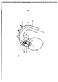
[00028] A presente invenção será descrita em mais detalhes no a seguir com referência aos desenhos nos quais As figuras 1-3 mostram uma primeira modalidade da presente invenção na qual a cabeça de bomba é ancorada por meio de uma extensão do cateter, pretendido para ser inserido no coração.[00028] The present invention will be described in more detail in the following with reference to the drawings in which Figures 1-3 show a first embodiment of the present invention in which the pump head is anchored by means of a catheter extension, intended for be inserted into the heart.
[00029] As figuras 4-6 mostram uma segunda modalidade da presente invenção na qual a cabeça de bomba é ancorada por meio de uma extensão do cateter, pretendida para repousar em torno do lado de fora da válvula aórtica.[00029] Figures 4-6 show a second embodiment of the present invention in which the pump head is anchored by means of a catheter extension, intended to rest around the outside of the aortic valve.
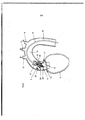
[00030] As figuras 7-9 mostram uma terceira modalidade da presente invenção na qual a cabeça de bomba é ancorada por meio de partes da gaiola circundando o propulsor, se estendendo para fora da gaiola e permanecendo contra a parede do vaso sanguíneo.[00030] Figures 7-9 show a third embodiment of the present invention in which the pump head is anchored by means of parts of the cage surrounding the propellant, extending out of the cage and remaining against the blood vessel wall.
[00031] As figuras 10-12 mostram uma quarta modalidade da presente invenção na qual a bomba é ancorada por e junto com um fio do cateter inserível fixado ao cateter próximo do rotor e que pode ser controlado a partir de fora.[00031] Figures 10-12 show a fourth embodiment of the present invention in which the pump is anchored by and together with an insertable catheter wire attached to the catheter near the rotor and which can be controlled from the outside.
[00032] A figura 1 mostra a extremidade distai de uma primeira modalidade do cateter de acordo com a presente invenção. 1 é uma cabeça de bomba consistindo de uma gaiola 2 contendo o propulsor 3 em um eixo de acionamento 4 conectado a um cabo de acionamento 5 que percorre através da manga 6. A cabeça de bomba 1 é mostrada em posição de trabalho e proporcionada com uma extensão 7 pretendida para ser trazida para dentro do coração como mostrado na figura 3.[00032] Figure 1 shows the distal end of a first embodiment of the catheter according to the present invention. 1 is a pump head consisting of a
[00033] A figura 2 mostra a cabeça de bomba 1 na posição de inserção junto com um introdutor 8. A extensão 7 é a partir de sua forma natural mostrada na figurai estirada e inserida parcialmente dentro do introdutor 8.[00033] Figure 2 shows the pump head 1 in the insertion position together with an
[00034] A figura 3 mostra o cateter em posição de trabalho com a sua extensão 7 inserida no coração 9. Os detalhes a seguir são importantes para o funcionamento da bomba:[00034] Figure 3 shows the catheter in working position with its
[00035] 10 a válvula aortic 11 a aorta ascendente 12 a curva aortic 13, 14 as artérias carótida 15 a artéria subclávia 16 a aorta descendente 17 a artéria coronária esquerda 18 a artéria coronária direita[00035] 10 the
[00036] Os detalhes de 20 e 21 serão descritos no a seguir.[00036] The details of 20 and 21 will be described in the following.
[00037] Como mostrado na figura 3, a extensão 7 tem um comprimento de um tal modo, que se a extremidade distai T da extensão 7 suporta contra a parede do coração 9 o propulsor 3 e a gaiola 2 são posicionados fora do coração 9 mas na aorta ascendente 11 próximo da válvula aórtica 10.[00037] As shown in figure 3, the
[00038] As figuras 4, 5 e 6 mostram a extremidade distai de uma segunda modalidade do cateter de acordo com a presente invenção em posição de trabalho. A diferença é que a extensão 7a tem a forma natural de um círculo ou uma seção de um círculo ou uma espiral, mas que pode ser inserida no introdutor 8 em uma forma retilínea como mostrado na figura 5. Inserida a mesma retornará para a sua forma natural suportando a cabeça de bomba 1 que se encontra em torno do lado de fora da válvula aórtica 10. Como mostrado na figura 5 e 6 o círculo, seção de um círculo ou espiral, a extensão 7a é localizada em um plano sendo perpendicular ao eixo longitudinal do cateter. Ademais, a extensão 7a tem em sua extremidade distal a ponta distal 7a', sendo localizada na posição ancorada direto na posição proximal da válvula aórtica para permitir o posicionamento do dispositivo na aorta ascendente 11.[00038] Figures 4, 5 and 6 show the distal end of a second embodiment of the catheter according to the present invention in working position. The difference is that the extension 7a has the natural shape of a circle or a section of a circle or a spiral, but that it can be inserted in the
[00039] As figuras 7, 8 e 9 mostram uma terceira modalidade do cateter de acordo com a presente invenção. A diferença é que a gaiola 2 consistindo de bandas, fios ou tiras expansíveis a partir de uma posição próxima ao eixo de acionamento 4 para formar a gaiola tem algumas bandas, fios ou tiras ou partes 2a das mesmas arranjadas para se estender para fora a partir de a gaiola de modo a contatar a parede do vaso sanguíneo e ancorar a gaiola com o propulsor embutido na posição desejada.[00039] Figures 7, 8 and 9 show a third embodiment of the catheter according to the present invention. The difference is that the
[00040] Uma segunda modalidade com base no mesmo princípio é que os filamentos são fixados em um anel na ponta da cabeça de bomba separada a partir da gaiola. Os filamentos são durante inserção paralelos e em paralelo ao eixo rotacional da cabeça de bomba. Os mesmos são construídos de modo que a forma natural faz com que os mesmos se desviem radialmente e se fixem contra a parede do vaso quando posicionados. A vantagem é que os filamentos são dispostos em um prolongamento da cabeça de bomba para evitar um maior diâmetro da gaiola.[00040] A second modality based on the same principle is that the filaments are fixed in a ring at the tip of the pump head separated from the cage. The filaments are inserted during parallel and parallel to the rotational axis of the pump head. They are constructed in such a way that the natural shape causes them to deviate radially and fix themselves against the vessel wall when positioned. The advantage is that the filaments are arranged in an extension of the pump head to avoid a larger diameter of the cage.
[00041] As figuras 10, 11 e 12 mostram uma quarta modalidade do cateter de acordo com a presente invenção. A diferença é que um fio 19 é fixado próximo à cabeça de bomba 1 de modo a ser inserido junto com o cateter. O fio 19 é controlado a partir de fora e pode, portanto ser usado para determinar a posição da cabeça de bomba 1 na aorta ascendente 11.[00041] Figures 10, 11 and 12 show a fourth embodiment of the catheter according to the present invention. The difference is that a
[00042] Por uma posição da cabeça de bomba 1 na aorta ascendente 11 logo acima da válvula aórtica 10 um fluxo reverso é proporcionado como mostrado pelas setas 20. O referido fluxo reverso aumentará o fluxo de sangue para as artérias coronárias esquerda e direita 17,18. Ao mesmo tempo o fluxo comum da bomba21 aumenta o fluxo de sangue para as artérias carótidas 13,14 e a artéria subclávia 15.[00042] By a position of the pump head 1 in the ascending
[00043] Vantagens especiais são obtidas quando se fixa a cabeça de bomba na aorta ascendente, mas, evidentemente, pode também ser uma vantagem se fixar a posição quando usado, por exemplo, na aorta descendente.[00043] Special advantages are obtained when fixing the pump head to the ascending aorta, but, of course, it can also be an advantage if fixing the position when used, for example, in the descending aorta.
Claims (3)
Applications Claiming Priority (3)
| Application Number | Priority Date | Filing Date | Title |
|---|---|---|---|
| SE0900637-0 | 2009-05-18 | ||
| SE0900637 | 2009-05-18 | ||
| PCT/EP2010/056772 WO2010133567A1 (en) | 2009-05-18 | 2010-05-18 | Catheter pump |
Publications (3)
| Publication Number | Publication Date |
|---|---|
| BRPI1010988A2 BRPI1010988A2 (en) | 2018-03-06 |
| BRPI1010988B1 true BRPI1010988B1 (en) | 2020-07-07 |
| BRPI1010988B8 BRPI1010988B8 (en) | 2021-06-22 |
Family
ID=42455375
Family Applications (1)
| Application Number | Title | Priority Date | Filing Date |
|---|---|---|---|
| BRPI1010988A BRPI1010988B8 (en) | 2009-05-18 | 2010-05-18 | "catheter pump" |
Country Status (9)
| Country | Link |
|---|---|
| US (1) | US8617239B2 (en) |
| EP (1) | EP2432515B1 (en) |
| JP (1) | JP5641546B2 (en) |
| CN (1) | CN102438674B (en) |
| BR (1) | BRPI1010988B8 (en) |
| DE (1) | DE202010016802U1 (en) |
| ES (1) | ES2486252T3 (en) |
| RU (1) | RU2553938C2 (en) |
| WO (1) | WO2010133567A1 (en) |
Families Citing this family (100)
| Publication number | Priority date | Publication date | Assignee | Title |
|---|---|---|---|---|
| US7393181B2 (en) | 2004-09-17 | 2008-07-01 | The Penn State Research Foundation | Expandable impeller pump |
| JP2009530041A (en) | 2006-03-23 | 2009-08-27 | ザ・ペン・ステート・リサーチ・ファンデーション | Cardiac assist device with expandable impeller pump |
| EP2194278A1 (en) | 2008-12-05 | 2010-06-09 | ECP Entwicklungsgesellschaft mbH | Fluid pump with a rotor |
| EP2216059A1 (en) | 2009-02-04 | 2010-08-11 | ECP Entwicklungsgesellschaft mbH | Catheter device with a catheter and an actuation device |
| EP2229965A1 (en) | 2009-03-18 | 2010-09-22 | ECP Entwicklungsgesellschaft mbH | Fluid pump with particular form of a rotor blade |
| EP2246078A1 (en) | 2009-04-29 | 2010-11-03 | ECP Entwicklungsgesellschaft mbH | Shaft assembly with a shaft which moves within a fluid-filled casing |
| EP2248544A1 (en) | 2009-05-05 | 2010-11-10 | ECP Entwicklungsgesellschaft mbH | Fluid pump with variable circumference, particularly for medical use |
| EP2266640A1 (en) | 2009-06-25 | 2010-12-29 | ECP Entwicklungsgesellschaft mbH | Compressible and expandable turbine blade for a fluid pump |
| EP2282070B1 (en) | 2009-08-06 | 2012-10-17 | ECP Entwicklungsgesellschaft mbH | Catheter device with a coupling device for a drive device |
| EP2298372A1 (en) | 2009-09-22 | 2011-03-23 | ECP Entwicklungsgesellschaft mbH | Rotor for an axial pump for transporting a fluid |
| EP2298371A1 (en) | 2009-09-22 | 2011-03-23 | ECP Entwicklungsgesellschaft mbH | Function element, in particular fluid pump with a housing and a transport element |
| EP2298373A1 (en) | 2009-09-22 | 2011-03-23 | ECP Entwicklungsgesellschaft mbH | Fluid pump with at least one turbine blade and a seating device |
| DK3441616T3 (en) | 2009-09-22 | 2023-05-30 | Ecp Entw Mbh | COMPRESSIBLE ROTOR FOR A FLUID PUMP |
| EP2314331B1 (en) | 2009-10-23 | 2013-12-11 | ECP Entwicklungsgesellschaft mbH | Catheter pump arrangement and flexible shaft arrangement with a cable core |
| EP2314330A1 (en) | 2009-10-23 | 2011-04-27 | ECP Entwicklungsgesellschaft mbH | Flexible shaft arrangement |
| US8690749B1 (en) | 2009-11-02 | 2014-04-08 | Anthony Nunez | Wireless compressible heart pump |
| EP2338541A1 (en) | 2009-12-23 | 2011-06-29 | ECP Entwicklungsgesellschaft mbH | Radial compressible and expandable rotor for a fluid pump |
| EP2338540A1 (en) | 2009-12-23 | 2011-06-29 | ECP Entwicklungsgesellschaft mbH | Delivery blade for a compressible rotor |
| EP2338539A1 (en) | 2009-12-23 | 2011-06-29 | ECP Entwicklungsgesellschaft mbH | Pump device with a detection device |
| EP2347778A1 (en) | 2010-01-25 | 2011-07-27 | ECP Entwicklungsgesellschaft mbH | Fluid pump with a radially compressible rotor |
| EP2363157A1 (en) | 2010-03-05 | 2011-09-07 | ECP Entwicklungsgesellschaft mbH | Device for exerting mechanical force on a medium, in particular fluid pump |
| EP2388029A1 (en) | 2010-05-17 | 2011-11-23 | ECP Entwicklungsgesellschaft mbH | Pump array |
| EP2399639A1 (en) | 2010-06-25 | 2011-12-28 | ECP Entwicklungsgesellschaft mbH | System for introducing a pump |
| EP2407185A1 (en) | 2010-07-15 | 2012-01-18 | ECP Entwicklungsgesellschaft mbH | Radial compressible and expandable rotor for a pump with a turbine blade |
| EP2407187A3 (en) | 2010-07-15 | 2012-06-20 | ECP Entwicklungsgesellschaft mbH | Blood pump for invasive application within the body of a patient |
| EP2407186A1 (en) | 2010-07-15 | 2012-01-18 | ECP Entwicklungsgesellschaft mbH | Rotor for a pump, produced with an initial elastic material |
| EP2422735A1 (en) | 2010-08-27 | 2012-02-29 | ECP Entwicklungsgesellschaft mbH | Implantable blood transportation device, manipulation device and coupling device |
| US8485961B2 (en) | 2011-01-05 | 2013-07-16 | Thoratec Corporation | Impeller housing for percutaneous heart pump |
| US9138518B2 (en) | 2011-01-06 | 2015-09-22 | Thoratec Corporation | Percutaneous heart pump |
| EP2497521A1 (en) | 2011-03-10 | 2012-09-12 | ECP Entwicklungsgesellschaft mbH | Push device for axial insertion of a string-shaped, flexible body |
| US9162017B2 (en) | 2011-08-29 | 2015-10-20 | Minnetronix, Inc. | Expandable vascular pump |
| US8849398B2 (en) | 2011-08-29 | 2014-09-30 | Minnetronix, Inc. | Expandable blood pump for cardiac support |
| EP2564771A1 (en) | 2011-09-05 | 2013-03-06 | ECP Entwicklungsgesellschaft mbH | Medicinal product with a functional element for invasive use in the body of a patient |
| US8926492B2 (en) | 2011-10-11 | 2015-01-06 | Ecp Entwicklungsgesellschaft Mbh | Housing for a functional element |
| DE102012202411B4 (en) * | 2012-02-16 | 2018-07-05 | Abiomed Europe Gmbh | INTRAVASAL BLOOD PUMP |
| US9327067B2 (en) | 2012-05-14 | 2016-05-03 | Thoratec Corporation | Impeller for catheter pump |
| EP4218887A1 (en) | 2012-05-14 | 2023-08-02 | Tc1 Llc | Mechanical circulatory support device for stabilizing a patient after cardiogenic shock |
| US9446179B2 (en) | 2012-05-14 | 2016-09-20 | Thoratec Corporation | Distal bearing support |
| US9872947B2 (en) | 2012-05-14 | 2018-01-23 | Tc1 Llc | Sheath system for catheter pump |
| US8721517B2 (en) | 2012-05-14 | 2014-05-13 | Thoratec Corporation | Impeller for catheter pump |
| CN108742951B (en) | 2012-06-06 | 2021-05-25 | 洋红医疗有限公司 | Artificial kidney valve |
| US9421311B2 (en) | 2012-07-03 | 2016-08-23 | Thoratec Corporation | Motor assembly for catheter pump |
| US9358329B2 (en) | 2012-07-03 | 2016-06-07 | Thoratec Corporation | Catheter pump |
| EP4186557A1 (en) | 2012-07-03 | 2023-05-31 | Tc1 Llc | Motor assembly for catheter pump |
| US9636441B2 (en) * | 2012-11-05 | 2017-05-02 | Robert Jarvik | Support stent for transvalvular conduit |
| US11077294B2 (en) | 2013-03-13 | 2021-08-03 | Tc1 Llc | Sheath assembly for catheter pump |
| JP2016509950A (en) | 2013-03-13 | 2016-04-04 | マジェンタ・メディカル・リミテッド | Kidney pump |
| US11033728B2 (en) | 2013-03-13 | 2021-06-15 | Tc1 Llc | Fluid handling system |
| EP4122520A1 (en) | 2013-03-13 | 2023-01-25 | Tc1 Llc | Fluid handling system |
| US10583231B2 (en) | 2013-03-13 | 2020-03-10 | Magenta Medical Ltd. | Blood pump |
| WO2014164292A1 (en) * | 2013-03-15 | 2014-10-09 | Minnetronix, Inc. | Expandable blood pump for cardiac support |
| EP3797810A1 (en) | 2013-03-15 | 2021-03-31 | Tc1 Llc | Catheter pump assembly including a stator |
| US9308302B2 (en) | 2013-03-15 | 2016-04-12 | Thoratec Corporation | Catheter pump assembly including a stator |
| DE102013208038B4 (en) | 2013-05-02 | 2016-09-08 | Michael Siegenthaler | Catheter-based cardiac assist system |
| US9764113B2 (en) | 2013-12-11 | 2017-09-19 | Magenta Medical Ltd | Curved catheter |
| WO2015160990A1 (en) | 2014-04-15 | 2015-10-22 | Thoratec Corporation | Catheter pump introducer systems and methods |
| US9827356B2 (en) | 2014-04-15 | 2017-11-28 | Tc1 Llc | Catheter pump with access ports |
| US10583232B2 (en) | 2014-04-15 | 2020-03-10 | Tc1 Llc | Catheter pump with off-set motor position |
| EP3131615B1 (en) | 2014-04-15 | 2021-06-09 | Tc1 Llc | Sensors for catheter pumps |
| DK3142721T3 (en) * | 2014-05-13 | 2022-05-30 | Abiomed Inc | CANYLE DEVICE |
| US9801720B2 (en) * | 2014-06-19 | 2017-10-31 | 4Tech Inc. | Cardiac tissue cinching |
| EP3583973A1 (en) | 2014-08-18 | 2019-12-25 | Tc1 Llc | Guide features for percutaneous catheter pump |
| WO2016118777A1 (en) | 2015-01-22 | 2016-07-28 | Thoratec Corporation | Reduced rotational mass motor assembly for catheter pump |
| EP3598986B1 (en) | 2015-01-22 | 2021-02-17 | Tc1 Llc | Motor assembly with heat exchanger for catheter pump |
| US9675738B2 (en) | 2015-01-22 | 2017-06-13 | Tc1 Llc | Attachment mechanisms for motor of catheter pump |
| US9907890B2 (en) | 2015-04-16 | 2018-03-06 | Tc1 Llc | Catheter pump with positioning brace |
| US11291824B2 (en) | 2015-05-18 | 2022-04-05 | Magenta Medical Ltd. | Blood pump |
| CN107080871B (en) * | 2016-02-16 | 2020-11-13 | 上海微创医疗器械(集团)有限公司 | Catheter sheath and ventricular assist circulation device |
| EP3487550B1 (en) | 2016-07-21 | 2022-09-28 | Tc1 Llc | Gas-filled chamber for catheter pump motor assembly |
| US11160970B2 (en) | 2016-07-21 | 2021-11-02 | Tc1 Llc | Fluid seals for catheter pump motor assembly |
| US11039915B2 (en) | 2016-09-29 | 2021-06-22 | Magenta Medical Ltd. | Blood vessel tube |
| US10556048B2 (en) | 2016-10-24 | 2020-02-11 | Heartware, Inc. | Blood pump with in-situ attaching motor stators |
| EP3556409B1 (en) | 2016-10-25 | 2022-01-05 | Magenta Medical Ltd. | Ventricular assist device |
| CN110049792B (en) | 2016-11-23 | 2022-01-18 | 马真塔医药有限公司 | Blood pump |
| CA3049227A1 (en) * | 2017-01-06 | 2018-07-12 | Benjamin Sun | Implantable intravascular ventricular assist device |
| DE102017102825A1 (en) * | 2017-02-13 | 2018-08-16 | Cardiobridge Gmbh | Catheter pump with drive unit and catheter |
| DE102017102823A1 (en) * | 2017-02-13 | 2018-08-16 | Cardiobridge Gmbh | Catheter pump with a pump head for insertion into the arterial vasculature |
| DE102017102828A1 (en) * | 2017-02-13 | 2018-08-16 | Cardiobridge Gmbh | Catheter pump with a pump head for insertion into the arterial vasculature |
| DE102017102824A1 (en) * | 2017-02-13 | 2018-08-16 | Cardiobridge Gmbh | Catheter pump with drive unit and catheter |
| AU2018280236A1 (en) | 2017-06-07 | 2020-01-16 | Shifamed Holdings, Llc | Intravascular fluid movement devices, systems, and methods of use |
| DE102017212193A1 (en) * | 2017-07-17 | 2019-01-17 | Robert Bosch Gmbh | A rotor assembly for a cardiac assist system and method of manufacturing a rotor assembly for a cardiac assist system |
| JP7319266B2 (en) | 2017-11-13 | 2023-08-01 | シファメド・ホールディングス・エルエルシー | Intravascular fluid transfer devices, systems and methods of use |
| CN111556764B (en) | 2018-01-10 | 2023-07-07 | 马真塔医药有限公司 | Ventricular assist device |
| US10905808B2 (en) | 2018-01-10 | 2021-02-02 | Magenta Medical Ltd. | Drive cable for use with a blood pump |
| DE102018201030A1 (en) | 2018-01-24 | 2019-07-25 | Kardion Gmbh | Magnetic coupling element with magnetic bearing function |
| CN112004563A (en) | 2018-02-01 | 2020-11-27 | 施菲姆德控股有限责任公司 | Intravascular blood pump and methods of use and manufacture |
| JP2021518249A (en) | 2018-03-20 | 2021-08-02 | セカンド・ハート・アシスト・インコーポレイテッド | Circulation auxiliary pump |
| US10893927B2 (en) | 2018-03-29 | 2021-01-19 | Magenta Medical Ltd. | Inferior vena cava blood-flow implant |
| US11690997B2 (en) | 2018-04-06 | 2023-07-04 | Puzzle Medical Devices Inc. | Mammalian body conduit intralumenal device and lumen wall anchor assembly, components thereof and methods of implantation and explanation thereof |
| WO2019229727A1 (en) | 2018-06-01 | 2019-12-05 | Jesus Flores | Catheter pump with fixed-diameter impeller |
| US20210220634A1 (en) * | 2018-06-12 | 2021-07-22 | Venstramedical Pty Limited | Intracardiac percutaneous pump for circulatory support and related systems and methods |
| DE102018211327A1 (en) | 2018-07-10 | 2020-01-16 | Kardion Gmbh | Impeller for an implantable vascular support system |
| CN115137967A (en) | 2019-01-24 | 2022-10-04 | 马真塔医药有限公司 | Ventricular assist device |
| EP3996797A4 (en) | 2019-07-12 | 2023-08-02 | Shifamed Holdings, LLC | Intravascular blood pumps and methods of manufacture and use |
| US11654275B2 (en) | 2019-07-22 | 2023-05-23 | Shifamed Holdings, Llc | Intravascular blood pumps with struts and methods of use and manufacture |
| US11724089B2 (en) | 2019-09-25 | 2023-08-15 | Shifamed Holdings, Llc | Intravascular blood pump systems and methods of use and control thereof |
| DE102020102474A1 (en) | 2020-01-31 | 2021-08-05 | Kardion Gmbh | Pump for conveying a fluid and method for manufacturing a pump |
| CN113995952B (en) * | 2021-10-25 | 2022-11-04 | 苏州心擎医疗技术有限公司 | Catheter device |
| US11484700B1 (en) * | 2021-10-25 | 2022-11-01 | Yossi Gross | Mechanical treatment of heart failure |
| CN115430039B (en) * | 2022-03-29 | 2024-03-08 | 心擎医疗(苏州)股份有限公司 | Catheter pump and method for folding pump head of catheter pump |
Family Cites Families (5)
| Publication number | Priority date | Publication date | Assignee | Title |
|---|---|---|---|---|
| US4753221A (en) * | 1986-10-22 | 1988-06-28 | Intravascular Surgical Instruments, Inc. | Blood pumping catheter and method of use |
| US4919647A (en) * | 1988-10-13 | 1990-04-24 | Kensey Nash Corporation | Aortically located blood pumping catheter and method of use |
| SE501215C2 (en) | 1992-09-02 | 1994-12-12 | Oeyvind Reitan | catheter Pump |
| CN1254598A (en) * | 1999-12-21 | 2000-05-31 | 马惠生 | Transplanted endarterial miniature auxiliary circulating device of ventricle |
| DE10336902C5 (en) | 2003-08-08 | 2019-04-25 | Abiomed Europe Gmbh | Intracardiac pumping device |
-
2010
- 2010-05-18 EP EP10720769.8A patent/EP2432515B1/en active Active
- 2010-05-18 RU RU2011148079/14A patent/RU2553938C2/en active
- 2010-05-18 JP JP2012511253A patent/JP5641546B2/en active Active
- 2010-05-18 ES ES10720769.8T patent/ES2486252T3/en active Active
- 2010-05-18 DE DE202010016802U patent/DE202010016802U1/en not_active Expired - Lifetime
- 2010-05-18 US US13/320,961 patent/US8617239B2/en active Active
- 2010-05-18 WO PCT/EP2010/056772 patent/WO2010133567A1/en active Application Filing
- 2010-05-18 BR BRPI1010988A patent/BRPI1010988B8/en active IP Right Grant
- 2010-05-18 CN CN201080021617.1A patent/CN102438674B/en active Active
Also Published As
| Publication number | Publication date |
|---|---|
| EP2432515A1 (en) | 2012-03-28 |
| JP5641546B2 (en) | 2014-12-17 |
| EP2432515B1 (en) | 2014-05-07 |
| US8617239B2 (en) | 2013-12-31 |
| CN102438674B (en) | 2014-11-05 |
| US20120059460A1 (en) | 2012-03-08 |
| WO2010133567A1 (en) | 2010-11-25 |
| BRPI1010988B8 (en) | 2021-06-22 |
| BRPI1010988A2 (en) | 2018-03-06 |
| DE202010016802U1 (en) | 2011-04-14 |
| ES2486252T3 (en) | 2014-08-18 |
| RU2011148079A (en) | 2013-06-27 |
| CN102438674A (en) | 2012-05-02 |
| RU2553938C2 (en) | 2015-06-20 |
| JP2012527269A (en) | 2012-11-08 |
Similar Documents
| Publication | Publication Date | Title |
|---|---|---|
| BRPI1010988B1 (en) | "catheter pump" | |
| US11925796B2 (en) | Motor assembly for catheter pump | |
| JP6638975B2 (en) | Transdermal systems, devices, and methods | |
| JP5473085B2 (en) | Catheter pump for circulatory assistance | |
| US9675738B2 (en) | Attachment mechanisms for motor of catheter pump | |
| US10729832B2 (en) | Implantable pump with tapered diffuser region | |
| US20230191108A1 (en) | Motor assembly for catheter pump | |
| CA2863234C (en) | Hemodynamic assist device | |
| CN110891624B (en) | Ventricular assist device and method | |
| CA2663586A1 (en) | Intravascular blood pump and catheter | |
| US20210220634A1 (en) | Intracardiac percutaneous pump for circulatory support and related systems and methods | |
| JP2014501554A (en) | Cannula with bifurcated tip for cardiac assist device | |
| TW202130376A (en) | Intravascular blood pump | |
| WO2021062566A1 (en) | Modular impeller system for fluid circulation | |
| US20230201560A1 (en) | Guidewire configurations for implantable medical devices | |
| CN109789255B (en) | Transcatheter device and system for delivering an in-vivo device | |
| ES2275651T3 (en) | CANCELLATION SYSTEM | |
| US20230149669A1 (en) | Guidewire guide configurations for implantable medical devices |
Legal Events
| Date | Code | Title | Description |
|---|---|---|---|
| B06F | Objections, documents and/or translations needed after an examination request according [chapter 6.6 patent gazette] | ||
| B06U | Preliminary requirement: requests with searches performed by other patent offices: procedure suspended [chapter 6.21 patent gazette] | ||
| B09A | Decision: intention to grant [chapter 9.1 patent gazette] | ||
| B16A | Patent or certificate of addition of invention granted [chapter 16.1 patent gazette] |
Free format text: PRAZO DE VALIDADE: 10 (DEZ) ANOS CONTADOS A PARTIR DE 07/07/2020, OBSERVADAS AS CONDICOES LEGAIS. |
|
| B16C | Correction of notification of the grant [chapter 16.3 patent gazette] |
Free format text: PRAZO DE VALIDADE: 20 (VINTE) ANOS CONTADOS A PARTIR DE 18/05/2010, OBSERVADAS AS CONDICOES LEGAIS. PATENTE CONCEDIDA CONFORME ADI 5.529/DF, QUE DETERMINA A ALTERACAO DO PRAZO DE CONCESSAO |