BRPI1009552B1 - rotation apparatus, rotation system and rotation method - Google Patents
rotation apparatus, rotation system and rotation method Download PDFInfo
- Publication number
- BRPI1009552B1 BRPI1009552B1 BRPI1009552-7A BRPI1009552A BRPI1009552B1 BR PI1009552 B1 BRPI1009552 B1 BR PI1009552B1 BR PI1009552 A BRPI1009552 A BR PI1009552A BR PI1009552 B1 BRPI1009552 B1 BR PI1009552B1
- Authority
- BR
- Brazil
- Prior art keywords
- panel
- rotation
- wheel
- tower
- wheel axle
- Prior art date
Links
- 238000000034 method Methods 0.000 title claims description 17
- 238000006073 displacement reaction Methods 0.000 claims abstract description 72
- 230000014759 maintenance of location Effects 0.000 claims abstract description 33
- 239000011253 protective coating Substances 0.000 claims description 17
- 239000011248 coating agent Substances 0.000 claims 1
- 238000000576 coating method Methods 0.000 claims 1
- 238000005096 rolling process Methods 0.000 claims 1
- 230000008878 coupling Effects 0.000 description 5
- 238000010168 coupling process Methods 0.000 description 5
- 238000005859 coupling reaction Methods 0.000 description 5
- 230000008901 benefit Effects 0.000 description 2
- 230000001681 protective effect Effects 0.000 description 2
- 239000004677 Nylon Substances 0.000 description 1
- 230000007423 decrease Effects 0.000 description 1
- 238000012986 modification Methods 0.000 description 1
- 230000004048 modification Effects 0.000 description 1
- 229920001778 nylon Polymers 0.000 description 1
- 230000035939 shock Effects 0.000 description 1
- 238000011144 upstream manufacturing Methods 0.000 description 1
Images


Classifications
-
- B—PERFORMING OPERATIONS; TRANSPORTING
- B64—AIRCRAFT; AVIATION; COSMONAUTICS
- B64F—GROUND OR AIRCRAFT-CARRIER-DECK INSTALLATIONS SPECIALLY ADAPTED FOR USE IN CONNECTION WITH AIRCRAFT; DESIGNING, MANUFACTURING, ASSEMBLING, CLEANING, MAINTAINING OR REPAIRING AIRCRAFT, NOT OTHERWISE PROVIDED FOR; HANDLING, TRANSPORTING, TESTING OR INSPECTING AIRCRAFT COMPONENTS, NOT OTHERWISE PROVIDED FOR
- B64F5/00—Designing, manufacturing, assembling, cleaning, maintaining or repairing aircraft, not otherwise provided for; Handling, transporting, testing or inspecting aircraft components, not otherwise provided for
- B64F5/10—Manufacturing or assembling aircraft, e.g. jigs therefor
Landscapes
- Engineering & Computer Science (AREA)
- Manufacturing & Machinery (AREA)
- Transportation (AREA)
- Aviation & Aerospace Engineering (AREA)
- Conveying And Assembling Of Building Elements In Situ (AREA)
- Automatic Assembly (AREA)
- Load-Engaging Elements For Cranes (AREA)
- Attitude Control For Articles On Conveyors (AREA)
- Testing Of Balance (AREA)
- Manipulator (AREA)
Abstract
APARELHO DE ROTAÇÃO A presente invenção refere-se a um aparelho de rotação que inclui uma torre configurada para se deslocar sobre uma base, um ascensor configurado para se elevar e se rebaixar ao longo da torre, uma porção de retenção de alvo configurada para reter um alvo de rotação, uma base de deslocamento de roda, um eixo de roda fixado, de modo giratório, à porção de retenção de alvo, e uma trava de eixo de roda. O eixo de roda inclui uma configurada para rolar sobre a base de deslocamento de roda. A porção de retenção de alvo é fixada ao ascensor através de um eixo de rotação paralelo ao eixo de roda. A trava de eixo de roda é configurada para travar o eixo de roda de tal modo que a roda não role sobre a base de deslocamento de roda e o eixo de roda possa girar em relação à porção de retenção de alvo.ROTATION APPLIANCE The present invention relates to a rotating apparatus that includes a tower configured to move on a base, an elevator configured to rise and lower along the tower, a target retention portion configured to retain a rotation target, a wheel displacement base, a wheel axle pivotally attached to the target retaining portion, and a wheel axle lock. The wheel axle includes one configured to roll on the wheel displacement base. The target retaining portion is fixed to the lift via a rotation axis parallel to the wheel axis. The wheel axle lock is configured to lock the wheel axle in such a way that the wheel does not roll over the wheel displacement base and the wheel axle can rotate with respect to the target holding portion.
Description
[001] A presente invenção refere-se a um aparelho de rotação.[001] The present invention relates to a rotating apparatus.
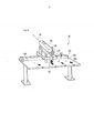
[002] Reportando-se à Figura 1, explica-se um processo de montagem de uma asa principal de uma aeronave. Um painel lateral superior 85 em uma atitude com um lado de face convexa 85a orientado para cima e um lado de face côncava 85b orientado para baixo é fixado a um lado superior de uma estrutura de asa 87, e um painel lateral inferior 86 em uma atitude com um lado de face convexa 86a orientado para baixo e um lado de face côncava 86b orientado para cima é fixado a um lado inferior da estrutura de asa 87.[002] Referring to Figure 1, an assembly process for an aircraft's main wing is explained. An
[003] Em um processo a montante do processo de montagem, o painel superior 85 é volteado de tal modo que o lado de face convexa 85a se torne orientado para cima, e o painel lateral inferior 86 é volteado de tal modo que o lado de face convexa 86a se torne voltado para baixo.[003] In a process upstream of the assembly process, the
[004] A Patente Japonesa No. 3614612 e a Publicação de Patente Japonesa (JP-A- Heisei 4-331106) descrevem aparelhos de rotação convencionais.[004] Japanese Patent No. 3614612 and Japanese Patent Publication (JP-A-Heisei 4-331106) describe conventional rotating apparatus.
[005] Literatura de Patente 1: Patente Japonesa No. 3614612[005] Patent Literature 1: Japanese Patent No. 3614612
[006] Literatura de Patente 2: Publicação de Patente Japonesa (JP-A-Heisei 4331106)[006] Patent Literature 2: Japanese Patent Publication (JP-A-Heisei 4331106)
[007] Um objetivo da presente invenção consiste em proporcionar um aparelho de rotação, um sistema de rotação, e um método de rotação que possam voltear um alvo de rotação em duas direções.[007] An object of the present invention is to provide a rotation apparatus, a rotation system, and a rotation method that can rotate a rotation target in two directions.
[008] Em um primeiro aspecto da presente invenção, um aparelho de rotação inclui: uma torre configurada para se deslocar sobre uma base; um ascensor configurado para se elevar e se rebaixar ao longo da torre; uma porção de retenção de alvo configurada para reter um alvo de rotação; uma base de deslocamento de roda; um eixo de roda fixado, de modo giratório, à porção de retenção de alvo; e uma trava de eixo de roda. O eixo de roda inclui uma configurada para rolar sobre a base de deslocamento de roda. A porção de retenção de alvo é fixada ao ascensor através de um eixo de rotação paralelo ao eixo de roda. A trava de eixo de roda é configurada para travar o eixo de roda de tal modo que a roda não role sobre a base de deslocamento de roda e o eixo de roda possa girar em relação à porção de retenção de alvo.[008] In a first aspect of the present invention, a rotating apparatus includes: a tower configured to move on a base; an elevator configured to rise and lower along the tower; a target holding portion configured to retain a rotating target; a wheel displacement base; a wheel axle pivotally attached to the target holding portion; and a wheel axle lock. The wheel axle includes one configured to roll on the wheel displacement base. The target retaining portion is fixed to the lift via a rotation axis parallel to the wheel axis. The wheel axle lock is configured to lock the wheel axle in such a way that the wheel does not roll over the wheel displacement base and the wheel axle can rotate with respect to the target holding portion.
[009] De preferência, o aparelho de rotação inclui, ainda, um dispositivo de controle. O dispositivo de controle faz com que a porção de retenção de alvo volteie em uma primeira direção de rotação fazendo-se com que o ascensor fique em um estado onde a trava de eixo de roda não trava o eixo de roda e em um estado onde a torre é parada com o eixo de rotação posicionado em um lado dianteiro de primeira direção do eixo de roda. O dispositivo de controle faz com que a porção de retenção de alvo volteie em uma segunda direção de rotação oposta à primeira direção de rotação controlando-se um deslocamento da torre e a subida e descida do ascensor de tal modo que o eixo de rotação execute um movimento circular no qual um centro é o eixo de roda em um estado onde a trava de eixo de roda trava o eixo de roda. O dispositivo de controle faz com que a torre se desloque em direção a um lado posterior da primeira direção ao voltear a porção de retenção de alvo na segunda direção de rotação.[009] Preferably, the rotating apparatus also includes a control device. The control device causes the target retaining portion to rotate in a first direction of rotation causing the lift to be in a state where the wheel axle lock does not lock the wheel axle and in a state where the tower is stopped with the axis of rotation positioned on a front end of the first direction of the wheel axle. The control device causes the target retaining portion to rotate in a second direction of rotation opposite to the first direction of rotation by controlling a displacement of the tower and the rise and fall of the lift in such a way that the axis of rotation performs a circular movement in which a center is the wheel axle in a state where the wheel axle lock locks the wheel axle. The control device causes the turret to move towards a rear side of the first direction by turning the target holding portion in the second direction of rotation.
[010] De preferência, o aparelho de rotação inclui, ainda, um acoplador. A base de deslocamento de roda inclui: uma porção fixa fixada em relação à base; e uma porção de seguimento de torre configurada de modo que seja capaz de se deslocar paralelamente à torre. A trava de eixo de roda é proporcionada à porção de seguimento de torre. O acoplador acopla a porção de seguimento de torre à torre.[010] Preferably, the rotating apparatus also includes a coupler. The wheel displacement base includes: a fixed portion fixed in relation to the base; and a tower tracking portion configured so that it is able to move parallel to the tower. The wheel axle lock is provided to the tower tracking portion. The coupler couples the turret tracking portion to the turret.
[011] De preferência, a base de deslocamento de roda inclui um ascensor de eixo de roda configurado para elevar e rebaixar o eixo de roda.[011] Preferably, the wheel displacement base includes a wheel axle lift configured to raise and lower the wheel axle.
[012] De preferência, a porção de retenção de alvo inclui: uma armação; e um dispositivo de fixação fixado à armação. O eixo de roda é fixado, de modo giratório, à armação. A armação é fixada ao ascensor através do eixo de rotação. O dispositivo de fixação fixa o alvo de rotação.[012] Preferably, the target holding portion includes: a frame; and a fixing device attached to the frame. The wheel axle is pivotally attached to the frame. The frame is fixed to the lift via the axis of rotation. The fixing device fixes the rotation target.
[013] De preferência, o dispositivo de fixação inclui uma placa de face configurada para tocar o alvo de rotação. A placa de face é permutável.[013] Preferably, the fixture includes a face plate configured to touch the rotation target. The face plate is interchangeable.
[014] De preferência, o dispositivo de fixação é fixado à armação de tal modo que uma posição do dispositivo de fixação seja ajustável.[014] Preferably, the fixing device is attached to the frame in such a way that a position of the fixing device is adjustable.
[015] Em um segundo aspecto da presente invenção, um sistema de rotação inclui: um dispositivo de suporte de borda do painel configurado para suportar uma porção de borda de um painel a partir de uma posição sob a porção de borda; um dispositivo de suporte de face do painel no qual o painel se apóia; e um aparelho de rotação. O aparelho de rotação inclui: uma torre configurada para se deslocar sobre uma base; um ascensor configurado para elevar e rebaixar a torre; uma porção de retenção do painel configurada para receber o painel a partir do dispositivo de suporte de borda do painel e do dispositivo de suporte de face do painel e reter o painel; uma base de deslocamento de roda; um eixo de roda fixado, de modo giratório, à porção de retenção do painel; e uma trava de eixo de roda. O eixo de roda inclui uma roda configurada para rolar sobre a base de deslocamento de roda. A porção de retenção do painel é fixada ao ascensor através de um eixo de rotação paralelo ao eixo de roda. A trava de eixo de roda é configurada para travar o eixo de roda de tal modo que a roda não role sobre a base de deslocamento de roda e o eixo de roda possa girar em relação à porção de retenção do painel.[015] In a second aspect of the present invention, a rotation system includes: a panel edge support device configured to support a panel edge portion from a position under the edge portion; a panel face support device on which the panel rests; and a rotating apparatus. The rotating apparatus includes: a tower configured to move on a base; an elevator configured to raise and lower the tower; a panel retention portion configured to receive the panel from the panel edge support device and the face panel support device and retain the panel; a wheel displacement base; a wheel axle pivotally attached to the retaining portion of the panel; and a wheel axle lock. The wheel axle includes a wheel configured to roll on the wheel displacement base. The retaining portion of the panel is fixed to the lift by means of an axis of rotation parallel to the wheel axis. The wheel axle lock is configured to lock the wheel axle in such a way that the wheel does not roll over the wheel displacement base and the wheel axle can rotate in relation to the panel retaining portion.
[016] De preferência, o dispositivo de suporte de borda do painel inclui: uma porção de recebimento de painel configurada para suportar a porção de borda; e os dispositivos de alimentação configurados para elevar e rebaixar a porção de recebimento de painel e mover a porção de recebimento de painel para frente e para trás nas direções de deslocamento da torre.[016] Preferably, the panel edge support device includes: a panel receiving portion configured to support the edge portion; and the feeding devices configured to raise and lower the panel receiving portion and moving the panel receiving portion back and forth in the travel directions of the tower.
[017] De preferência, a porção de recebimento de painel inclui: um corpo deslizante configurado para que seja elevado e rebaixado, e movido para frente e para trás pelos dispositivos de alimentação; uma porção de suporte de bloco configurada para se elevar e se rebaixar em relação ao corpo deslizante; um bloco de recebimento de painel fixado à porção de suporte de bloco e configurado para suportar a porção de borda; e uma primeira mola configurada para orientar a porção de suporte de bloco para cima. O corpo deslizante inclui um batente. Quando se chocar contra o batente, a porção de suporte de bloco para o rebaixamento em relação ao corpo deslizante.[017] Preferably, the panel receiving portion includes: a sliding body configured to be raised and lowered, and moved back and forth by the feeding devices; a block support portion configured to raise and lower in relation to the sliding body; a panel receiving block fixed to the block support portion and configured to support the edge portion; and a first spring configured to orient the block support portion upwards. The sliding body includes a stop. When hitting the stop, the block support portion for lowering in relation to the sliding body.
[018] De preferência, o bloco de recebimento de painel é fixado à porção de suporte de bloco de tal modo que o bloco de recebimento de painel possa se mover para frente e para trás nas direções de deslocamento da torre. A porção de recebimento de painel inclui uma segunda mola configurada para receber a força de uma direção de deslocamento da torre que atua sobre o bloco de recebimento de painel.[018] Preferably, the panel receiving block is attached to the block support portion in such a way that the panel receiving block can move back and forth in the travel directions of the tower. The panel receiving portion includes a second spring configured to receive the force of a direction of travel of the tower acting on the panel receiving block.
[019] De preferência, a porção de recebimento de painel inclui uma porção entalhada. O dispositivo de suporte de borda do painel inclui um detector configurado para detectar que a porção de borda está posicionada na porção entalhada.[019] Preferably, the panel receiving portion includes a notched portion. The panel edge support device includes a detector configured to detect that the edge portion is positioned on the notched portion.
[020] De preferência, o sistema de rotação inclui, ainda, um revestimento de proteção fixado à porção de borda. A porção de borda inclui: uma primeira porção revestida pelo re-vestimento de proteção; e uma segunda porção não revestida pelo revestimento de proteção. O detector inclui: uma porção de emissão de luz; e uma porção de recebimento de luz. A porção de emissão de luz e a porção de recebimento de luz são dispostas de tal modo que a segunda porção bloqueie uma trajetória de luz entre a porção de emissão de luz e a porção de recebimento de luz quando o revestimento de proteção tocar a porção entalhada.[020] Preferably, the rotation system also includes a protective coating attached to the edge portion. The edge portion includes: a first portion coated by the protective coating; and a second portion uncoated by the protective coating. The detector includes: a light-emitting portion; and a light receiving portion. The light-emitting portion and the light-receiving portion are arranged in such a way that the second portion blocks a light path between the light-emitting portion and the light-receiving portion when the protective coating touches the notched portion .
[021] De preferência, o sistema de rotação inclui, ainda, um revestimento de proteção fixado à porção de borda. O revestimento de proteção toca o dispositivo de suporte de borda do painel.[021] Preferably, the rotation system also includes a protective coating attached to the edge portion. The protective coating touches the edge support device of the panel.
[022] De preferência, o dispositivo de suporte de face do painel inclui: uma pluralidade de porções de suporte do painel que suporta o painel; e uma pluralidade de dispositivos de alimentação configurados para mover respectivamente a pluralidade de porções de suporte do painel para frente e para trás. A pluralidade de dispositivos de alimentação dispõe a pluralidade de porções de suporte do painel sobre um plano curvado predeterminado.[022] Preferably, the face panel support device includes: a plurality of panel support portions that support the panel; and a plurality of feeding devices configured to move the plurality of support portions of the panel forward and backward respectively. The plurality of feeding devices disposes the plurality of support portions of the panel on a predetermined curved plane.
[023] De preferência, o sistema de rotação inclui, ainda, uma ferramenta de posicio-namento. A ferramenta de posicionamento inclui: uma mesa; um guia deslizante proporcionadoà mesa; uma base deslizante configurada para deslizar ao longo do guia deslizante; um ponteiro a laser suportado pela base deslizante; e uma porção de travamento configura- da para travar a base deslizante à mesa em uma posição arbitrária entre uma pluralidade de posições predeterminadas.[023] Preferably, the rotation system also includes a positioning tool. The positioning tool includes: a table; a sliding guide provided to the table; a sliding base configured to slide along the sliding guide; a laser pointer supported by the sliding base; and a locking portion configured to lock the sliding base to the table in an arbitrary position among a plurality of predetermined positions.
[024] Em um terceiro aspecto da presente invenção, um método de rotação inclui: uma etapa de voltear uma porção de retenção de alvo em uma primeira direção de rotação; e uma etapa de voltear a porção de retenção de alvo em uma segunda direção de rotação oposta à primeira direção de rotação. Um eixo de roda é fixado, de modo giratório, à porção de retenção de alvo. A porção de retenção de alvo é fixada a um ascensor através de um eixo de rotação paralelo ao eixo de roda. O ascensor é configurado de modo que seja capaz de se elevar e se rebaixar ao longo da torre. A etapa de voltear a porção de retenção de alvo na primeira direção de rotação inclui uma etapa de uma roda do eixo de roda que rola sobre uma base de deslocamento de roda enquanto se rebaixa o ascensor. A etapa de voltear a porção de retenção de alvo na segunda direção de rotação inclui uma etapa de deslocamento da torre, e elevação e rebaixamento do ascensor de tal modo que o eixo de rotação execute um movimento circular no qual um centro é o eixo de roda, enquanto fixa uma posição do eixo de roda.[024] In a third aspect of the present invention, a method of rotation includes: a step of turning a target holding portion in a first direction of rotation; and a step of turning the target holding portion in a second direction of rotation opposite to the first direction of rotation. A wheel axle is pivotally attached to the target holding portion. The target retaining portion is attached to a lift via an axis of rotation parallel to the wheel axis. The lift is configured so that it is able to rise and lower along the tower. The step of turning the target holding portion in the first direction of rotation includes a step of a wheel of the wheel axle which rolls on a wheel displacement base while lowering the lift. The step of turning the target holding portion in the second direction of rotation includes a step of displacing the tower, and raising and lowering the lift in such a way that the axis of rotation performs a circular movement in which a center is the wheel axis. , while fixing a wheel axle position.
[025] De acordo com a presente invenção, proporciona-se um aparelho de rotação, um sistema de rotação, e um método de rotação que podem voltear um alvo de rotação em duas direções.[025] According to the present invention, there is provided a rotation apparatus, a rotation system, and a rotation method that can rotate a rotation target in two directions.
[026] Os objetivos, vantagens e recursos da presente invenção se tornarão mais aparentes a partir da descrição das modalidades tomada em conjunto com os desenhos em anexo, onde: A Figura 1 mostra um processo de montagem de uma asa principal; A Figura 2 é uma vista de topo de um aparelho de rotação de um sistema de rotação de acordo com uma primeira modalidade da presente invenção; A Figura 3 é uma vista lateral do aparelho de rotação; A Figura 4 é uma vista lateral de uma porção de retenção do painel do aparelho de rotação; A Figura 5 é uma vista lateral de um dispositivo de suporte de face do painel e de um dispositivo de suporte de borda do painel do sistema de rotação; A Figura 6 é uma vista em corte local de um painel da asa principal; A Figura 7 mostra uma estrutura detalhada de uma porção de recebimento de painel do dispositivo de suporte de borda do painel; A Figura 8 é uma vista em perspectiva de uma ferramenta de posicionamento do sistema de rotação; A Figura 9 mostra uma etapa de rebaixar o painel da asa principal suspenso a partir de uma barra de carga; A Figura 10 mostra uma etapa da porção de recebimento de painel que engata uma porção de borda do painel da asa principal; A Figura 11 mostra uma etapa de posicionar a porção de borda do painel da asa principal; A Figura 12 mostra uma etapa de posicionar as porções de suporte do painel do dispositivo de suporte de face do painel; A Figura 13 mostra uma etapa de apoiar o painel da asa principal sobre as porções de suporte do painel; A Figura 14 mostra uma etapa de movimentar a porção de retenção do painel para frente até uma posição de recebimento do painel da asa principal; A Figura 15 mostra uma relação posicional entre o painel da asa principal e a porção de retenção do painel na posição de recebimento do painel da asa principal; A Figura 16 mostra uma etapa da porção de retenção do painel que fixa o painel da asa principal; A Figura 17 mostra uma etapa de movimentar a porção de retenção do painel para trás a partir da posição de recebimento do painel da asa principal; A Figura 18 mostra uma etapa de voltear a porção de retenção do painel em uma primeira direção de rotação; A Figura 19 mostra uma etapa de erguer a porção de retenção do painel; A Figura 20 mostra uma etapa de rebaixar a porção de retenção do painel para transferir o painel da asa principal a um AGV (Veículo Guiado Automaticamente); A Figura 21 mostra uma etapa do AGV que recebe o painel da asa principal a partir da porção de retenção do painel; A Figura 22 mostra uma etapa de fixar o painel da asa principal a um lado inferior de uma estrutura de asa; A Figura 23 mostra uma etapa de rebaixar a porção de retenção do painel para permutar as placas de face; A Figura 24 mostra uma etapa de voltear a porção de retenção do painel em uma segunda direção de rotação oposta à primeira direção de rotação; A Figura 25 mostra uma etapa de um gabarito de eslinga que recebe um painel da asa principal a partir da porção de retenção do painel; e A Figura 26 mostra uma etapa de fixar o painel da asa principal a um lado superior da estrutura de asa.[026] The objectives, advantages and resources of the present invention will become more apparent from the description of the modalities taken in conjunction with the attached drawings, where: Figure 1 shows a process for assembling a main wing; Figure 2 is a top view of a rotation apparatus for a rotation system according to a first embodiment of the present invention; Figure 3 is a side view of the rotating apparatus; Figure 4 is a side view of a retaining portion of the panel of the rotating apparatus; Figure 5 is a side view of a panel face support device and a panel edge support device of the rotation system; Figure 6 is a local cross-sectional view of a main wing panel; Figure 7 shows a detailed structure of a panel receiving portion of the panel edge support device; Figure 8 is a perspective view of a tool for positioning the rotation system; Figure 9 shows a step of lowering the main wing panel suspended from a load bar; Figure 10 shows a step of the panel receiving portion that engages a panel edge portion of the main wing; Figure 11 shows a step of positioning the edge portion of the main wing panel; Figure 12 shows a step of positioning the panel support portions of the panel face support device; Figure 13 shows a step of supporting the main wing panel on the support portions of the panel; Figure 14 shows a step of moving the retaining portion of the panel forward to a receiving position of the main wing panel; Figure 15 shows a positional relationship between the main wing panel and the retaining portion of the panel in the receiving position of the main wing panel; Figure 16 shows a step of the panel retaining portion that secures the main wing panel; Figure 17 shows a step of moving the retaining portion of the panel backwards from the receiving position of the main wing panel; Figure 18 shows a step of turning the retaining portion of the panel in a first direction of rotation; Figure 19 shows a step of lifting the retaining portion of the panel; Figure 20 shows a step of lowering the panel retaining portion to transfer the main wing panel to an AGV (Automatically Guided Vehicle); Figure 21 shows an AGV step that receives the main wing panel from the retention portion of the panel; Figure 22 shows a step of securing the main wing panel to an underside of a wing structure; Figure 23 shows a step of lowering the retaining portion of the panel to exchange the face plates; Figure 24 shows a step of turning the retention portion of the panel in a second direction of rotation opposite to the first direction of rotation; Figure 25 shows a step of a sling template that receives a main wing panel from the retention portion of the panel; and Figure 26 shows a step of securing the main wing panel to an upper side of the wing structure.
[027] Com referência aos desenhos em anexo, descrevem-se, abaixo, as modalidades de um aparelho de rotação, um sistema de rotação, e um método de rotação de acordo com a presente invenção.[027] With reference to the attached drawings, the modalities of a rotation apparatus, a rotation system, and a rotation method according to the present invention are described below.
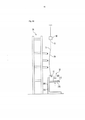
[028] Reportando-se à Figura 2, um sistema de rotação de acordo com uma primeira modalidade da presente invenção inclui um aparelho de rotação 10. O aparelho de rotação inclui bases de deslocamento de torre 100, bases de deslocamento de roda 110, torres de deslocamento 120, ascensores 121, uma porção de retenção do painel 130, eixos de rotação 135, eixos de roda 137, e um dispositivo de controle 140. Na Figura 2, mostram-se a direção X, a direção Y, e a direção Z. A direção X é uma primeira direção horizontal, a direção Y é uma segunda direção horizontal perpendicular à primeira direção horizontal, e a direção Z é uma direção vertical. A base de deslocamento de torre 100 inclui guias de torre 101, seguindo os guias de porção 102, e um dispositivo de alimentação 105. O dispositivo de alimentação 105 aciona a torre de deslocamento 120 na direção Y e posiciona a torre de deslocamento 120. O dispositivo de alimentação 105 inclui, por exemplo, um fuso de esferas. A torre de deslocamento 120 é orientada pelos guias de torre 101 de modo a se deslo- car sobre a base de deslocamento de torre 100. A torre de deslocamento 120 inclui um acoplador 122. O ascensor 121 é orientado pela torre de deslocamento 120 para subir e descer ao longo da torre de deslocamento 120 na direção Z. A base de deslocamento de roda 110 inclui uma porção fixa 111 fixada à base de deslocamento de torre 100, uma porção de seguimento de torre 112 posicionada em um lado dianteiro da direção Y da porção fixa 111, um ascensor de eixo de roda 113 posicionado em um lado traseiro da direção Y da porção fixa 111, uma trava de eixo de roda 114, e um acoplador 115. A trava de eixo de roda 114 e o acoplador 115 são proporcionados à porção de seguimento de torre 112. O acoplador 115 inclui um pino de acoplamento 116. Quando o pino de acoplamento 116 engatar o acoplador 122, a torre de deslocamento 120 e a porção de seguimento de torre 112 são acopladas. Quando o engate entre o pino de acoplamento 116 e a torre de deslocamento 120 for liberado, libera-se o acoplamento entre a torre de deslocamento 120 e a porção de seguimento de torre 112. A porção de seguimento de torre 112 é orientada pelas guias de porção de seguimento 102 de modo a se deslocar sobre a base de deslocamento de torre 100. A base de deslocamento de roda 110 tem uma superfície de deslocamento 110a. A superfície de deslocamento 110a inclui uma superfície de deslocamento 111a como uma superfície superior da porção fixa 111, uma superfície de deslocamento 112a como uma superfície superior da porção de seguimento de torre 112, e uma superfície de deslocamento 113a como uma superfície superior do ascensor de eixo de roda 113. A porção de retenção do painel 130 inclui uma armação 131. O eixo de roda 137 é fixado, de modo giratório, à armação 131. O eixo de roda 137 inclui uma roda 136 que rola sobre a superfície de deslocamento 110a. A armação 131 é fixada ao ascensor 121 através do eixo de rotação. O eixo de rotação 135 e o eixo de roda 137 são paralelos à direção X. Uma região 90 é posicionada no lado dianteiro da direção Y da porção de retenção do painel 130.[028] Referring to Figure 2, a rotation system according to a first embodiment of the present invention includes a
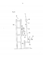
[029] Reportando-se à Figura 3, a torre de deslocamento 120 inclui um dispositivo de alimentação 125. O dispositivo de alimentação 125 aciona o ascensor 121 para cima e para baixo e posiciona o ascensor 121. O dispositivo de alimentação 125 inclui, por exemplo, um fuso de esferas. A superfície de deslocamento 111a, a superfície de deslocamento 112a, e a superfície de deslocamento 113a são dispostas no mesmo nível. O aparelho de rotação 10 inclui os dispositivos de alimentação 118. O dispositivo de alimentação 118 aciona o ascensor de eixo de roda 113 para cima e para baixo e posiciona o ascensor de eixo de roda 113. Visto que o ascensor de eixo de roda 113 sobe e desce, a superfície de deslocamento 113a é disposta em uma posição superior e em uma posição inferior em relação à superfície de deslocamento 111a. Quando a roda 136 estiver sobre a superfície de deslocamento 113, a subida e a descida do ascensor de eixo de roda 113 causam a subida e a descida do eixo de roda 137. Quando a trava de eixo de roda 114 subir para engatar o eixo de roda 137 em um estado onde a roda 136 se encontra sobre a superfície de deslocamentos 112a, o eixo de roda 137 é travado de tal modo que a roda 136 não role sobre a superfície de deslocamento 110a e o eixo de roda 137 possa girar em relação à porção de retenção do painel 130. Quando a trava de eixo de roda 114 descer para liberar o engate entre a trava de eixo de roda 114 e o eixo de roda 137, a roda 136 pode rolar livremente sobre a superfície de deslocamento 110a. A porção de retenção do painel 130 mantém um alvo de rotação. A armação 131 inclui um lado de retenção 131a como um lado no qual se mantém o alvo de rotação.[029] Referring to Figure 3, the
[030] Reportando-se à Figura 4, a porção de retenção do painel 130 inclui dispositivos de fixação 132 proporcionados ao lado de retenção 131a. Os dispositivos de fixação fixam o alvo de rotação. Os dispositivos de fixação 132 são fixados à armação 131 de tal modo que as posições dos dispositivos de fixação 132 sejam ajustáveis. As posições dos dispositivos de fixação 132 são ajustadas de modo que sejam compatíveis ao tamanho do alvo de rotação. O dispositivo de fixação 132 inclui uma porção de suporte de placa de face móvel 133, uma placa de face 133a fixada à porção de suporte de placa de face móvel 133, uma porção de suporte de placa de face fixa 134, e uma placa de face 134a fixada à porção de suporte de placa de face fixa 134. A porção de suporte de placa de face fixa 134 é fixada à armação 131 de tal modo que a posição da porção de suporte de placa de face fixa 134 seja ajustável. A porção de suporte de placa de face fixa 134 suporta a porção de suporte de placa de face móvel 133 de tal modo que a porção de suporte de placa de face móvel 133 possa oscilar. O dispositivo de fixação 132 fixa o alvo de rotação de tal modo que o alvo de rotação seja colocado entre a placa de face 133a e a placa de face 134a. Neste momento, a placa de face 133a e a placa de face 134a tocam o alvo de rotação. A placa de face 133a e a placa de face 134a são permutáveis. Utilizando-se a placa de face 133a e a placa de face 134a que são compatíveis ao formato do alvo de rotação, evita-se que o alvo de rotação seja danificado.[030] Referring to Figure 4, the retention portion of the
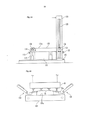
[031] Reportando-se à Figura 5, o sistema de rotação de acordo com a presente modalidade inclui um dispositivo de suporte de face do painel 20 e uma pluralidade de dispositivos de suporte de borda do painel 30. O dispositivo de suporte de face do painel 20 e os dispositivos de suporte de borda do painel 30 são dispostos na região 90. A pluralidade dos dispositivos de suporte de borda do painel 30 é disposta no lado dianteiro da direção Y da porção de retenção do painel 130, e o dispositivo de suporte de face do painel 20 é disposto no lado dianteiro da direção Y da pluralidade de dispositivos de suporte de borda do painel 30. A pluralidade de dispositivos de suporte de borda do painel 30 é disposta na direção X.[031] Referring to Figure 5, the rotation system according to the present embodiment includes a face support device of the
[032] O dispositivo de suporte de face do painel 20 inclui uma estrutura de armação 200, uma pluralidade de porções de suporte do painel 201, uma pluralidade de dispositivos de alimentação 202. A estrutura de armação 200 suporta a pluralidade de dispositivos de alimentação 202. A pluralidade de dispositivos de alimentação 202 suporta, respectivamente, a pluralidade de porções de suporte do painel 201. A pluralidade de dispositivos de alimentação 202 move, respectivamente, a pluralidade de porções de suporte do painel 201 para frente e para trás na direção Y. A pluralidade de porções de suporte do painel 201 é distribuída em uma região que se propaga na direção X e na direção Z. Por exemplo, a pluralidade de porções de suporte do painel 201 é disposta ao longo de uma pluralidade de linhas retas paralelas à direção X. A pluralidade de linhas retas são diferentes umas das outras na posição da direção Z.[032] The face support device of the
[033] O dispositivo de suporte de borda do painel 30 inclui uma base de armação 300, um corpo deslizante no eixo geométrico Z 310, e uma porção de recebimento de painel 320. O corpo deslizante no eixo geométrico Z 310 é suportado pela base de armação 300 de tal modo que o corpo deslizante no eixo geométrico Z 310 possa subir e descer na direção Z. A base de armação 300 inclui um dispositivo de alimentação 305. O dispositivo de alimentação 305 eleva e rebaixa o corpo deslizante no eixo geométrico Z 310 e posiciona o corpo deslizante no eixo geométrico Z 310. O dispositivo de alimentação 305 inclui, por exemplo, um fuso de esferas. A porção de recebimento de painel 320 é suportada pelo corpo deslizante no eixo geométrico Z 310 de tal modo que a porção de recebimento de painel 320 possa se mover para frente e para trás nas direções de deslocamento (direção Y) da torre de deslocamento 120. O corpo deslizante no eixo geométrico Z inclui um dispositivo de alimentação 315. O dispositivo de alimentação 315 move a porção de recebimento de painel 320 para frente e para trás na direção Y e posiciona a porção de recebimento de painel 320. O dispositivo de alimentação 315 inclui, por exemplo, um fuso de esferas. O dispositivo de alimentação 305 e o dispositivo de alimentação 315 elevam e rebaixam a porção de recebimento de painel 320 e movem a porção de recebimento de painel 320 para frente e para trás nas direções de deslocamento da torre de deslocamento 120.[033] The panel
[034] Um painel da asa principal 70 como o alvo de rotação é transportado para a posição entre a porção de retenção do painel 130 e o dispositivo de suporte de face do painel 20 em um estado onde o painel da asa principal 70 é suspenso através de um fio 51 a partir de uma barra de carga 50 que se estende na direção X. A direção de transporte do painel da asa principal 70 é a direção X. O painel da asa principal 70 inclui uma porção de borda 71, uma porção de borda 72, um lado de face convexa 70a, e um lado de face côncava 70b. A porção de borda 71 é uma entre a porção de borda anterior e a porção de borda posterior do painel da asa principal 70, e a porção de borda 72 é a outra entre a porção de borda anterior e a porção de borda posterior. O painel da asa principal 70 é suspenso pelo fio 51 na porção de borda 71 em um estado onde o lado de face convexa 70a é orientado em direção ao lado dianteiro da direção Y e a porção de borda 72 é posicionada no lado inferior.[034] A
[035] Reportando-se à Figura 6, descrevem-se os revestimentos de proteção 60 do sistema de rotação de acordo com a presente modalidade. Os revestimentos de proteção 60 são fixados à porção de borda 72 antes de o painel da asa principal 70 ser transportado até a posição entre a porção de retenção do painel 130 e o dispositivo de suporte de face do painel 20. O revestimento de proteção 60 inclui um membro de proteção 600 e uma porção de fixação do membro de proteção 610 que fixa o membro de proteção 610 à porção de borda 72. O revestimento de proteção 60 evita que a porção de borda 72 seja danificada.[035] Referring to Figure 6, the
[036] Reportando-se à Figura 7, descreve-se a porção de recebimento de painel 320. A porção de recebimento de painel 320 inclui um corpo deslizante no eixo geométrico Y 321, uma porção de suporte de bloco 322, um bloco de recebimento de painel 325, uma mola 326, molas 327, e um detector 330. O corpo deslizante no eixo geométrico Y 321 é movido para frente e para trás na direção Y pelo dispositivo de alimentação 315. O corpo deslizante no eixo geométrico Y 321 é erguido e rebaixado, e movido para frente e para trás na direção Y pelos dispositivos de alimentação 305 e 315. O corpo deslizante no eixo geométrico Y 321 inclui um batente 321a. A porção de suporte de bloco 322 é suportada pelo corpo deslizante no eixo geométrico Y 321 de tal modo que a porção de suporte de bloco 322 possa subir e descer em relação ao corpo deslizante no eixo geométrico Y 321. A mola 326 é fixada ao corpo deslizante no eixo geométrico Y 321 e orienta a porção de suporte de bloco 322 para cima. O bloco de recebimento de painel 325 é fixado à porção de suporte de bloco 322 de tal modo que o bloco de recebimento de painel 325 possa se mover para frente e para trás na direção Y em relação à porção de suporte de bloco 322. A mola 327 é proporcionada entre a porção de suporte de bloco 322 e o bloco de recebimento de painel 325 de tal modo que a mola 327 receba a força da direção Y que age sobre o bloco de recebimento de painel 325. Uma porção entalhada em formato de V 325a é formada no bloco de recebimento de painel 325. O bloco de recebimento de painel 325 toca o membro de proteção 600. O detector 330 inclui uma porção de emissão de luz 323 e uma porção de recebimento de luz 324. A porção de emissão de luz 323 e a porção de recebimento de luz 324 são fixadas à porção de suporte de bloco 322 ou ao bloco de recebimento de painel 325 de tal modo que a porção de emissão de luz 323 e a porção de recebimento de luz 324 fiquem uma voltada para a outra na direção Y. A porção de emissão de luz 323 e a porção de recebimento de luz 324 são dispostas de tal modo que uma trajetória de luz entre as mesmas seja deslocada na direção X a partir da porção entalhada 325a.[036] Referring to Figure 7, the receiving portion of
[037] Reportando-se à Figura 8, descreve-se uma ferramenta de posicionamento 40 do sistema de rotação de acordo com a presente modalidade. A ferramenta de posicionamento 40 inclui uma mesa 400, uma base deslizante 410, um ponteiro a laser 420, e uma cavilha de ajuste de ângulo 430. A mesa 400 inclui um guia deslizante 401 e cavilhas de batente 403. Proporcionam-se uma pluralidade de orifícios 402 e marcações de indexação 404 na mesa 400. A pluralidade de orifícios 402 corresponde, respectivamente, à pluralidade de marcações de indexação 404. A base deslizante 410 inclui um pino de fixação 411. A base deslizante 410 desliza ao longo do guia deslizante 401. As cavilhas de batente 403 limitam o deslizamento da base deslizante 403 em uma faixa definida. O ponteiro a laser 420 é suportado pela base deslizante 410 e emite um feixe de laser 99. A cavilha de ajuste de ângulo 430 é usada para ajustar a direção de emissão do feixe de laser 99. O pino de fixação 411 e os orifícios 402 travam a base deslizante 410 à mesa 400 em uma posição arbitrária entre uma a de posições predeterminadas. A pluralidade de posições predeterminadas corresponde, respectivamente, a um caso onde o painel da asa principal 70 é um painel lateral superior de uma asa principal direita, um caso onde o painel da asa principal 70 é um painel lateral inferior da asa principal direita, um caso onde o painel da asa principal 70 é um painel lateral superior de uma asa principal esquerda, e um caso onde o painel da asa principal 70 é um painel lateral inferior da asa principal esquerda.[037] Referring to Figure 8, a
[038] Descreve-se, abaixo, um método de rotação que utiliza o sistema de rotação de acordo com a presente modalidade. Em primeiro lugar, descreve-se um caso onde o painel da asa principal 70 é um painel lateral inferior.[038] A rotation method that uses the rotation system according to the present modality is described below. First, a case is described where the
[039] Reportando-se à Figura 5, o painel da asa principal 70 é transportado até a posição entre a porção de retenção do painel 130 e o dispositivo de suporte de face do painel 20. Visto que a porção de borda 71 é suspensa pelo fio 51, o próprio peso do painel da asa principal 70 diminui sua curvatura comparando-se ao formato projetado. No presente documento, os dispositivos de suporte de borda do painel 30 ficam localizados sob o painel da asa principal 70.[039] Referring to Figure 5, the
[040] Reportando-se à Figura 9, a barra de carga 50 é rebaixada até um nível prede-terminado.Após isto, a barra de carga 50 é movida na direção X de modo a ajustar a posição da direção X do painel da asa principal 70 de tal modo que o feixe de laser 99 seja irradiado em um ponto predeterminado do painel da asa principal 70. Visto que a posição do painel da asa principal 70 é diretamente confirmada utilizando-se o feixe de laser 99, o ali- nhamento do painel da asa principal 70 pode ser realizado com exatidão.[040] Referring to Figure 9, the
[041] Reportando-se à Figura 10, o dispositivo de alimentação 305 e o dispositivo de alimentação elevam a porção de recebimento de painel 320 até um nível predeterminado enquanto ajusta a posição da direção Y da porção de recebimento de painel 320 (ou após a posição da direção Y da porção de recebimento de painel 320 ser ajustada) de tal modo que a porção de borda 72 se engate ao bloco de recebimento de painel 325. Neste momento, a porção de borda 72 não alcança o fundo da porção entalhada 325a.[041] Referring to Figure 10, the
[042] Reportando-se à Figura 11, o dispositivo de alimentação 315 move a porção de recebimento de painel 320 (de modo mais concreto, o corpo deslizante no eixo geométrico y 321) voltado ao lado traseiro da direção Y até uma posição predeterminada da direção Y. Consequentemente, a porção de borda 72 é movida voltada ao lado traseiro da direção Y, e o painel da asa principal 70 é inclinado de tal modo que o lado de face convexa 70a seja obliquamente orientado para baixo.[042] Referring to Figure 11, the
[043] Reportando-se à Figura 12, a pluralidade de dispositivos de alimentação 202 dispõe a pluralidade de porções de suporte do painel 201 em um plano curvado predeterminado.[043] Referring to Figure 12, the plurality of feeding
[044] Reportando-se à Figura 13, a barra de carga 50 é rebaixada de modo a apoiar o painel da asa principal 70 sobre o dispositivo de suporte de face do painel 20. A pluralidade de porções de suporte do painel toca o lado de face convexa 70a e suporta o painel da asa principal 70. Neste momento, o membro de proteção 600 desliza ao longo de uma inclinação da porção entalhada 325a e é disposto na porção de fundo da porção entalhada 325a. A mola 326 absorve os choques devido ao solavanco entre o membro de proteção 600 e a porção de fundo da porção entalhada 325a. A partir do ponto de vista do grau de deslizamento e da resistência abrasiva, prefere-se que o membro de proteção 600 e o bloco de recebimento de painel 325 sejam formados por náilon MC (marca registrada). O fio 51 é descido e, portanto, o peso do painel da asa principal 70 que age sobre o bloco de recebimento de painel 325 é aumentado. Portanto, a porção de suporte de bloco 322 cai em relação ao corpo deslizante no eixo geométrico Y 321 e se colide contra o batente 321a a ser parado. O bloco de recebimento de painel 325 suporta a porção de borda 72 a partir de uma posição sob a porção de borda 72 em um estado onde a porção de borda 72 é disposta na porção entalhada 325a. Isto faz com que o painel da asa principal 70 tenha o formato projetado.[044] Referring to Figure 13, the
[045] Quando o detector 330 detectar que a porção de borda 72 é apropriadamente disposta na porção entalhada 325a, o método procede para a próxima etapa. A porção de borda 72 inclui uma primeira porção revestida pelo revestimento de proteção 60 e uma segundaporção não revestida pelo revestimento de proteção 60. Em um estado onde o revestimento de proteção 60 toca a porção entalhada 325a, a segunda porção bloqueia a trajetória de luz entre a porção de emissão de luz 323 e a porção de recebimento de luz 324. Com base no bloqueio, o detector 330 detecta que a porção de borda 72 é apropriadamente disposta na porção entalhada 325a. Visto que o detector 330 é usado para detectar diretamente a posição da porção de borda 72, o alinhamento da porção de borda 72 pode ser realizado com exatidão.[045] When
[046] Reportando-se à Figura 14, o dispositivo de controle 140 faz com que o acoplador 115 e o acoplador 122 se acoplem à torre de deslocamento 120 e à porção de seguimento de torre 122, e faz com que a trava de eixo de roda 114 trave o eixo de roda 137 de tal modo que roda 136 não role sobre a superfície de deslocamento 112a. O ascensor 121 e o eixo de rotação 135 são dispostos no lado dianteiro da direção Y e acima do eixo de roda 137. O lado de retenção 131a é obliquamente orientado para baixo voltado para o lado dianteiro da direção Y. O dispositivo de controle 140 faz com que o dispositivo de alimentação 105 desloque a torre de deslocamento 120 voltada para o lado dianteiro da direção Y. O ascensor 120, a porção de retenção do painel 130, e a porção de seguimento de torre 112 são movidos juntos à torre de deslocamento 120 voltada para o lado dianteiro da direção Y. Como resultado, a porção de retenção do painel 130 é movida até uma posição de recebimento predeterminada do painel da asa principal em um estado onde os dispositivos de fixação 132 são abertos.[046] Referring to Figure 14, the
[047] Reportando-se à Figura 15, após a porção de retenção do painel 130 se mover até a posição de recebimento predeterminada do painel da asa principal, o dispositivo de controle 140 faz com que o dispositivo de alimentação 105 pare a torre de deslocamento 120. Como resultado, a porção de retenção do painel 130 para na posição de tal modo que um pequeno vão seja formado entre a placa de face 134a e o lado de face côncava 70b. Mesmo quando a placa de face 134a se colidir contra o lado de face côncava 70b, as molas 327 evitam que o painel da asa principal 70 seja danificado.[047] Referring to Figure 15, after the retention portion of the
[048] Reportando-se à Figura 16, o dispositivo de controle 140 faz com que os dispositivos de fixação 132 fixem e retenham o painel da asa principal 70. O painel da asa principal 70 é mantido pela porção de retenção do painel 130 de tal modo que o lado de face convexa 70a e o lado de retenção 131a sejam orientados voltados para a mesma direção. O dispositivo de fixação 132 fixa o painel da asa principal 70 de tal modo que a placa de face 133a toque o lado de face convexa 70a e a placa de face 134a toque o lado de face côncava 70b. Visto que os dispositivos de fixação 132 retêm o painel da asa principal 70 de tal modo que o painel da asa principal 70 mantenha o formato projetado, evita-se que o painel da asa principal 70 seja danificado. Após a porção de retenção do painel 130 receber o painel da asa principal 70 a partir do dispositivo de suporte de face do painel 20 e dos dispositivos de suporte de borda do painel 30 desta forma, o fio 51 é liberado a partir da porção de borda 71, a barra de carga 50 é elevada, e os corpos deslizantes no eixo geométrico Z 310 são rebaixados.[048] Referring to Figure 16, the
[049] Reportando-se à Figura 17, o dispositivo de controle 140 faz com que o dispositivo de alimentação 105 mova a torre de deslocamento 120 em direção ao lado posterior da direção Y e pare em uma posição onde a superfície de deslocamento 112a é conectada à superfície de deslocamento 111a.[049] Referring to Figure 17, the
[050] Reportando-se à Figura 18, o dispositivo de controle 140 faz com que a trava de eixo de roda 114 libere a trava do eixo de roda 137. Enquanto se mantém a torre de deslocamento 120 parada em um estado onde o eixo de rotação 135 é posicionado no lado dianteiro da direção Y do eixo de roda 137, o dispositivo de alimentação 125 é induzido a rebaixar o ascensor 121 até um nível predeterminado. Visto que o ascensor 121 é rebaixado a partir de um estado onde o eixo de rotação 135 é posicionado no lado dianteiro da direção Y e acima do eixo de roda 137, a roda 136 rola em direção ao lado posterior da direção Y sobre a superfície de deslocamento 112a, a superfície de deslocamento 111a, e a superfície de deslocamento 113a com o ascensor 121 sendo rebaixado e, então, para sobre a superfície de deslocamento 113a. Consequentemente, a porção de retenção do painel 130 é volteada em uma primeira direção de rotação e o lado de retenção 131a se torna orientado para baixo.[050] Referring to Figure 18, the
[051] Reportando-se à Figura 19, o dispositivo de controle 140 faz com que o dispositivo de alimentação 125 e o dispositivo de alimentação 118 elevem o ascensor 121 e o ascensor de eixo de roda 113 até as posições verticais predeterminadas ao mesmo tempo. Consequentemente, a porção de retenção do painel 130 se eleva com o lado de retenção 131a sendo orientado para baixo. Após isto, um AGV (Veículo Guiado Automaticamente) 83 se move até a posição sob a porção de retenção do painel 130.[051] Referring to Figure 19, the
[052] Reportando-se à Figura 20, o dispositivo de controle 140 faz com que o dispositivo de alimentação 125 e o dispositivo de alimentação 118 rebaixem o ascensor 121 e o ascensor de eixo de roda 113 até as posições verticais predeterminadas ao mesmo tempo. Consequentemente, a porção de retenção do painel 130 cai com o lado de retenção 131a sendo orientado para baixo. Como resultado, as posições verticais do ascensor 121, do ascensor de eixo de roda 113, e da porção de retenção do painel 130, respectivamente, se tornam mais rebaixadas do que as posições verticais mostradas na Figura 18.[052] Referring to Figure 20, the
[053] Reportando-se à Figura 21, o AGV 83 inclui um gabarito 82. O dispositivo de controle 140 faz com que os dispositivos de fixação 132 se abram quando a porção de retenção do painel 130 estiver em um estado da Figura 20, portanto, o painel da asa principal 70 é transferido a partir da porção de retenção do painel 130 para o gabarito 82. O gabarito 82 suporta, a partir de uma posição sob o lado de face convexa 70a, o lado de face convexa 70a que é orientado para baixo.[053] Referring to Figure 21, the
[054] Novamente, o dispositivo de controle 140 faz com que o dispositivo de alimentação 125 e o dispositivo de alimentação 118 elevem o ascensor 121 e o ascensor de eixo de roda 113 até as posições verticais predeterminadas mostradas na Figura 19 ao mesmo tempo. Neste estado, o AGV 83 se move a partir da posição sob a porção de retenção do painel 130.[054] Again,
[055] Reportando-se à Figura 22, o painel da asa principal 70 é fixado a um lado infe rior de uma estrutura de asa 87 em um estado onde o lado de face convexa 70a é orientado para baixo.[055] Referring to Figure 22, the
[056] Reportando-se à Figura 23, após o AGV 83 se mover a partir da posição sob a porção de retenção do painel 130, o dispositivo de controle 140 faz com que o dispositivo de alimentação 125 e o dispositivo de alimentação 118 rebaixem o ascensor 121 e o ascensor de eixo de roda 113 até as posições verticais predeterminadas ao mesmo tempo. Consequentemente, a porção de retenção do painel 130 cai com o lado de retenção 131a sendo orientado para baixo. Como resultado, as posições verticais do ascensor 121, o ascensor de eixo de roda 113, e a porção de retenção do painel 130 se tornam, respectivamente, mais rebaixadas do que as posições verticais mostradas na Figura 20. Neste estado, as placas de face 133a e as placas de face 134a são trocadas por outras correspondentes a um painel lateral superior.[056] Referring to Figure 23, after the
[057] A seguir, descreve-se um método de rotação para um caso onde o painel da asa principal 70 é o painel lateral superior. O método de rotação para o caso onde o painel da asa principal 70 consiste no painel lateral superior é igual ao método para o caso onde o painel da asa principal 70 consiste no painel lateral inferior nas etapas antes de o aparelho de rotação 10 se tornar o estado mostrado na Figura 17.[057] The following describes a method of rotation for a case where the
[058] Reportando-se à Figura 24, o dispositivo de controle 140 faz com que o acoplador 115 libere o acoplamento entre a porção de seguimento de torre 112 e a torre de deslocamento 120. Enquanto faz com que a trava de eixo de roda 114 trave o eixo de roda 137 de modo a fixar a posição do eixo de roda 137, o dispositivo de controle 140 faz com que o dispositivo de alimentação 105 se desloque em direção ao lado posterior da direção Y e faz com que o dispositivo de alimentação 125 suba e desça o ascensor 121 de tal modo que o eixo de rotação 135 execute um movimento circular no qual um centro é o eixo de roda 137. De acordo com tal controle pelo dispositivo de controle 140, a porção de retenção do painel 130 é volteada em uma segunda direção de rotação oposta à primeira direção de rotação e o lado de retenção 131a se torna orientado para cima.[058] Referring to Figure 24, the
[059] Reportando-se à Figura 25, um gabarito de eslinga 81 suspenso a partir de um guindaste aéreo (não mostrado) retém com vácuo o lado de face convexa 70a orientado para cima a partir de uma posição acima do lado de face convexa 70a. O dispositivo de controle 140 faz com que os dispositivos de fixação 132 se abram, portanto, o painel da asa principal 70 é transferido a partir da porção de retenção do painel 130 até o gabarito de es- linga 81.[059] Referring to Figure 25, a
[060] Reportando-se à Figura 26, o painel da asa principal 70 é fixado a um lado superior da estrutura de asa 87 em um estado onde o lado de face convexa 70a é orientado para cima.[060] Referring to Figure 26, the
[061] De acordo com a presente modalidade, o painel da asa principal 70 pode ser volteado em duas direções utilizando-se um único aparelho. De acordo com a presente modalidade, pode-se poupar espaço operacional para voltear o painel da asa principal 70. De acordo com a presente modalidade, visto que uma precisão de posicionamento é excelente nas transferências mostradas na Figura 20 e na Figura 24, as transferências a partir da porção de retenção do painel 130 até o gabarito de eslinga 81 e o AGV 83 são fáceis. De acordo com a presente modalidade, quase todas as porções da operação de rotação podem ser automatizadas.[061] According to the present modality, the
[062] De acordo com a presente modalidade, assegura-se uma segurança operacional em uma rotação de um painel. De acordo com a presente modalidade, podem-se poupar horas de trabalho para uma rotação de um painel. De acordo com a presente modalidade, visto que se evita que um painel seja danificado, garante-se, com segurança, a qualidade do produto.[062] In accordance with the present modality, operational security is ensured when a panel is rotated. According to the present modality, hours of work can be saved for a rotation of a panel. According to the present modality, since a panel is prevented from being damaged, the quality of the product is safely guaranteed.
[063] O aparelho de rotação, o sistema de rotação, e o método de rotação de acordo com a presente modalidade são especialmente preferenciais para rotação de um painel grande, tal como um painel da asa principal de uma aeronave, e também são aplicáveis a uma rotação de outros alvos de rotação.[063] The rotation apparatus, the rotation system, and the rotation method according to the present modality are especially preferred for rotation of a large panel, such as an aircraft's main wing panel, and are also applicable to a rotation of other rotation targets.
[064] A presente invenção foi descrita com referência às modalidades; no entanto, a presente invenção não se limita às modalidades anteriores. Várias modificações podem ser aplicadas às modalidades anteriores.[064] The present invention has been described with reference to the modalities; however, the present invention is not limited to the foregoing embodiments. Several modifications can be applied to the previous modalities.
[065] Este pedido se baseia e reivindica o benefício de prioridade do Pedido de Patente Japonesa No. 2009-47137, depositado em 27 de fevereiro de 2009, estando a descri- ção do mesmo aqui incorporada em sua totalidade a título de referência.[065] This application is based on and claims the priority benefit of Japanese Patent Application No. 2009-47137, filed on February 27, 2009, the description of which is incorporated herein in its entirety for reference.
Claims (17)
Applications Claiming Priority (3)
| Application Number | Priority Date | Filing Date | Title |
|---|---|---|---|
| JP2009-047137 | 2009-02-27 | ||
| JP2009047137A JP5078928B2 (en) | 2009-02-27 | 2009-02-27 | Reversing device |
| PCT/JP2010/052382 WO2010098241A1 (en) | 2009-02-27 | 2010-02-17 | Turnover apparatus |
Publications (2)
| Publication Number | Publication Date |
|---|---|
| BRPI1009552A2 BRPI1009552A2 (en) | 2019-04-09 |
| BRPI1009552B1 true BRPI1009552B1 (en) | 2021-02-23 |
Family
ID=42665450
Family Applications (1)
| Application Number | Title | Priority Date | Filing Date |
|---|---|---|---|
| BRPI1009552-7A BRPI1009552B1 (en) | 2009-02-27 | 2010-02-17 | rotation apparatus, rotation system and rotation method |
Country Status (7)
| Country | Link |
|---|---|
| US (1) | US8616825B2 (en) |
| EP (1) | EP2402113B1 (en) |
| JP (1) | JP5078928B2 (en) |
| CN (1) | CN102333617B (en) |
| BR (1) | BRPI1009552B1 (en) |
| CA (1) | CA2753519C (en) |
| WO (1) | WO2010098241A1 (en) |
Families Citing this family (17)
| Publication number | Priority date | Publication date | Assignee | Title |
|---|---|---|---|---|
| CN104275506A (en) * | 2013-07-10 | 2015-01-14 | 诺德轮毂制造有限公司 | Special lathe for aluminum truck wheel valve holes |
| CN104589016A (en) * | 2014-12-01 | 2015-05-06 | 重庆红亿机械有限公司 | Height adjustable diesel engine body hydraumatic vertical turnover device |
| CN105643274A (en) * | 2016-03-30 | 2016-06-08 | 安徽合力股份有限公司 | Overturning mechanism for flexible connection differential mechanism assembling |
| KR102254605B1 (en) * | 2017-01-17 | 2021-05-20 | 가부시키가이샤 잉그 | Reversing device |
| KR102547723B1 (en) * | 2018-06-29 | 2023-06-27 | 주식회사 고영테크놀러지 | Flipper device and object inspection method using the same |
| CN109604995B (en) * | 2019-01-16 | 2023-07-14 | 沈阳飞机工业(集团)有限公司 | Frame overturning mechanism capable of being locked at any angle and use method |
| CN111731814A (en) * | 2020-06-22 | 2020-10-02 | 山东润德生物科技有限公司 | Continuous feed supplement distribution system and equipment thereof |
| CN111872622A (en) * | 2020-09-15 | 2020-11-03 | 山东鲁能光大钢结构有限公司 | A turning device and H-beam turning system |
| CN112958986B (en) * | 2021-02-08 | 2023-02-03 | 中国铁建重工集团股份有限公司 | Steel pipe ring overturning tool |
| CN113601084B (en) * | 2021-08-10 | 2023-02-10 | 青岛理工大学 | Automatic assembling, overturning and welding tool for side wall aluminum profiles of rail vehicles |
| CN115724173B (en) * | 2021-08-26 | 2025-04-29 | 中联重科股份有限公司 | Turning machine and control method thereof and excavator assembly line |
| CN115230985B (en) * | 2022-07-15 | 2024-08-23 | 芜湖航翼集成设备有限公司 | Self-adaptive flexible clamping and overturning equipment for autonomous connection of wings |
| CN115533663A (en) * | 2022-10-31 | 2022-12-30 | 常州市中海船舶螺旋桨有限公司 | Boats and ships screw is polished and is used roll-over stand |
| CN116674972B (en) * | 2023-05-25 | 2025-10-31 | 江苏申达检验股份有限公司 | Test apparatus for precast wall panels |
| CN116618716B (en) * | 2023-06-19 | 2025-08-22 | 湖南贝特新能源科技有限公司 | A drilling device for power electronic components |
| CN119501416B (en) * | 2024-11-28 | 2025-07-11 | 浙江久胜成铝业有限公司 | Welding equipment and method for metal aluminum plate of aluminum alloy door and window |
| CN120791455B (en) * | 2025-09-09 | 2025-12-05 | 江苏孚杰高端装备制造(集团)股份有限公司 | An automatic rotating device for ball valve processing |
Family Cites Families (21)
| Publication number | Priority date | Publication date | Assignee | Title |
|---|---|---|---|---|
| US2859884A (en) * | 1953-04-06 | 1958-11-11 | John H Pearce | Method and means for the erection of tip up walls |
| US3820234A (en) * | 1970-12-17 | 1974-06-28 | Ratier Sa Forest | Machining center with automatic tool changer |
| SU430048A1 (en) * | 1972-12-27 | 1974-05-30 | С. Р. Райгородский , Ж. Г. Гордин | METHOD OF INSTALLATION OF LONG-DIMENSIONAL DESIGNS IN THE VERTICAL POSITION |
| US3982636A (en) * | 1974-07-26 | 1976-09-28 | Seiji Furuto | Car lifting apparatus |
| JPS53122659A (en) * | 1977-04-01 | 1978-10-26 | Kawasaki Steel Co | Steel sheet reversing device |
| JPS58148099A (en) * | 1982-02-27 | 1983-09-03 | Mitsui Eng & Shipbuild Co Ltd | Method and jig for inverting plate material |
| JPH0825167B2 (en) | 1991-05-02 | 1996-03-13 | ミサワホーム株式会社 | Wooden panel manufacturing method |
| US5630696A (en) * | 1996-02-26 | 1997-05-20 | Tampa Hall Limited | Apparatus for positioning an object |
| JP3614612B2 (en) | 1997-05-13 | 2005-01-26 | アルプス電気株式会社 | Reversing device |
| JPH1179335A (en) * | 1997-09-02 | 1999-03-23 | Nippon Steel Weld Prod & Eng Co Ltd | Panel reversing device |
| US6430796B1 (en) | 2000-05-03 | 2002-08-13 | The Boeing Company | Apparatus for performing automated manufacturing operations on panel-shaped workpieces |
| US6578247B2 (en) * | 2000-08-31 | 2003-06-17 | International Truck Intellectual Property Company, Llc | Vehicle chassis inverter |
| US6575310B2 (en) * | 2001-02-09 | 2003-06-10 | Tc Development And Design | Motorcycle lift |
| EP1466847B1 (en) * | 2003-04-11 | 2004-11-17 | Tecnopat AG | Process and apparatus for laying down glass sheets |
| ES2245264B1 (en) * | 2005-04-11 | 2007-03-16 | Sistemas Tecnicos Encofrados, S.A. | ADJUSTABLE CLAMP FOR CLAMPING PANELS. |
| US7290976B2 (en) * | 2005-06-28 | 2007-11-06 | Applied Materials, Inc. | Semiconductor substrate processing apparatus with a passive substrate gripper |
| JP4941856B2 (en) * | 2006-07-19 | 2012-05-30 | デンソン株式会社 | Heavy object reversing device |
| JP2009047137A (en) | 2007-08-22 | 2009-03-05 | Calsonic Kansei Corp | Muffler for vehicle and its manufacturing method |
| US7794194B2 (en) * | 2007-09-14 | 2010-09-14 | Seagate Technology Llc | Pick and place work piece flipper |
| CN201183260Y (en) | 2008-02-27 | 2009-01-21 | 佛山市顺德区欧姆玻璃机械有限公司 | Mechanical glass automatic pick-up table |
| FR2929919B1 (en) * | 2008-04-14 | 2010-04-23 | Nexter Systems | METHOD OF RETURNING A STRUCTURE AND TOOLING ASSOCIATED WITH SUCH A METHOD |
-
2009
- 2009-02-27 JP JP2009047137A patent/JP5078928B2/en active Active
-
2010
- 2010-02-17 EP EP10746122.0A patent/EP2402113B1/en not_active Not-in-force
- 2010-02-17 WO PCT/JP2010/052382 patent/WO2010098241A1/en not_active Ceased
- 2010-02-17 US US13/203,032 patent/US8616825B2/en not_active Expired - Fee Related
- 2010-02-17 CA CA2753519A patent/CA2753519C/en active Active
- 2010-02-17 CN CN201080009600.4A patent/CN102333617B/en not_active Expired - Fee Related
- 2010-02-17 BR BRPI1009552-7A patent/BRPI1009552B1/en not_active IP Right Cessation
Also Published As
| Publication number | Publication date |
|---|---|
| CN102333617B (en) | 2014-02-12 |
| JP2010201522A (en) | 2010-09-16 |
| US8616825B2 (en) | 2013-12-31 |
| JP5078928B2 (en) | 2012-11-21 |
| CA2753519A1 (en) | 2010-09-02 |
| CN102333617A (en) | 2012-01-25 |
| WO2010098241A1 (en) | 2010-09-02 |
| CA2753519C (en) | 2013-11-12 |
| EP2402113B1 (en) | 2017-05-24 |
| EP2402113A1 (en) | 2012-01-04 |
| BRPI1009552A2 (en) | 2019-04-09 |
| EP2402113A4 (en) | 2014-04-23 |
| US20110311344A1 (en) | 2011-12-22 |
Similar Documents
| Publication | Publication Date | Title |
|---|---|---|
| BRPI1009552B1 (en) | rotation apparatus, rotation system and rotation method | |
| CN103359078B (en) | Vehicle alignment system for battery altering station | |
| EP3275809B1 (en) | Supporting device and supporting method for articles | |
| KR102374083B1 (en) | Optical axis shift detection method of substrate transfer robot and substrate holding hand | |
| BR112017012101B1 (en) | METHOD FOR POSITIONING A WORKPIECE | |
| US20100329823A1 (en) | Method and apparatus for delivery of a tubular to a drilling apparatus | |
| EP3523664B1 (en) | Manipulator | |
| TW201219282A (en) | Plate-shaped member transfer facility | |
| US20200020559A1 (en) | Ceiling transport vehicle system and teaching unit | |
| JP2011042309A (en) | Battery replacement positioning device of electric vehicle | |
| JP7347692B2 (en) | Transport vehicle system | |
| JP5343745B2 (en) | Vehicle battery exchange device | |
| WO2022267376A1 (en) | Transfer and mounting platform and method for motor train unit device compartment | |
| JP6825464B2 (en) | Teaching unit and ceiling carrier system | |
| US20240059204A1 (en) | Transport vehicle and method of using transport vehicle | |
| BR112020008507B1 (en) | AUTOMATICALLY GUIDED VEHICLE SUPPLIED WITH FORKS TO MOVE A TILE SUPPORT STRUCTURE | |
| JP4401829B2 (en) | Automatic teaching device for stacker crane | |
| JP7786352B2 (en) | Battery Swap Station | |
| TW521059B (en) | Manual guided carrying device | |
| US20040172170A1 (en) | Portable wheel alignment device | |
| CN223419510U (en) | Auxiliary installation device | |
| CN110668279A (en) | Elevator traction force detection robot and detection method thereof | |
| CN120306899B (en) | An intermittent automatic feeding fixture | |
| CN104455958B (en) | A kind of remote control location changing target body plug-in unit and upset system | |
| CN119287876A (en) | A steel cage positioning and lowering device and construction method thereof |
Legal Events
| Date | Code | Title | Description |
|---|---|---|---|
| B06F | Objections, documents and/or translations needed after an examination request according [chapter 6.6 patent gazette] | ||
| B06U | Preliminary requirement: requests with searches performed by other patent offices: procedure suspended [chapter 6.21 patent gazette] | ||
| B09A | Decision: intention to grant [chapter 9.1 patent gazette] | ||
| B16A | Patent or certificate of addition of invention granted [chapter 16.1 patent gazette] |
Free format text: PRAZO DE VALIDADE: 10 (DEZ) ANOS CONTADOS A PARTIR DE 23/02/2021, OBSERVADAS AS CONDICOES LEGAIS. |
|
| B21F | Lapse acc. art. 78, item iv - on non-payment of the annual fees in time |
Free format text: REFERENTE A 14A ANUIDADE. |
|
| B24J | Lapse because of non-payment of annual fees (definitively: art 78 iv lpi, resolution 113/2013 art. 12) |
Free format text: EM VIRTUDE DA EXTINCAO PUBLICADA NA RPI 2762 DE 12-12-2023 E CONSIDERANDO AUSENCIA DE MANIFESTACAO DENTRO DOS PRAZOS LEGAIS, INFORMO QUE CABE SER MANTIDA A EXTINCAO DA PATENTE E SEUS CERTIFICADOS, CONFORME O DISPOSTO NO ARTIGO 12, DA RESOLUCAO 113/2013. |