BRPI1009551B1 - inhibitor for a vehicle fuel system refueling inlet set and vehicle fuel system inlet bottleneck set - Google Patents
inhibitor for a vehicle fuel system refueling inlet set and vehicle fuel system inlet bottleneck set Download PDFInfo
- Publication number
- BRPI1009551B1 BRPI1009551B1 BRPI1009551-9A BRPI1009551A BRPI1009551B1 BR PI1009551 B1 BRPI1009551 B1 BR PI1009551B1 BR PI1009551 A BRPI1009551 A BR PI1009551A BR PI1009551 B1 BRPI1009551 B1 BR PI1009551B1
- Authority
- BR
- Brazil
- Prior art keywords
- movable
- nozzle
- inhibitor
- fact
- actuator
- Prior art date
Links
Images


Classifications
-
- B—PERFORMING OPERATIONS; TRANSPORTING
- B60—VEHICLES IN GENERAL
- B60K—ARRANGEMENT OR MOUNTING OF PROPULSION UNITS OR OF TRANSMISSIONS IN VEHICLES; ARRANGEMENT OR MOUNTING OF PLURAL DIVERSE PRIME-MOVERS IN VEHICLES; AUXILIARY DRIVES FOR VEHICLES; INSTRUMENTATION OR DASHBOARDS FOR VEHICLES; ARRANGEMENTS IN CONNECTION WITH COOLING, AIR INTAKE, GAS EXHAUST OR FUEL SUPPLY OF PROPULSION UNITS IN VEHICLES
- B60K15/00—Arrangement in connection with fuel supply of combustion engines or other fuel consuming energy converters, e.g. fuel cells; Mounting or construction of fuel tanks
- B60K15/03—Fuel tanks
- B60K15/04—Tank inlets
- B60K15/0406—Filler caps for fuel tanks
- B60K2015/0419—Self-sealing closure caps, e.g. that don't have to be removed manually
- B60K2015/0429—Self-sealing closure caps, e.g. that don't have to be removed manually actuated by the nozzle
-
- B—PERFORMING OPERATIONS; TRANSPORTING
- B60—VEHICLES IN GENERAL
- B60K—ARRANGEMENT OR MOUNTING OF PROPULSION UNITS OR OF TRANSMISSIONS IN VEHICLES; ARRANGEMENT OR MOUNTING OF PLURAL DIVERSE PRIME-MOVERS IN VEHICLES; AUXILIARY DRIVES FOR VEHICLES; INSTRUMENTATION OR DASHBOARDS FOR VEHICLES; ARRANGEMENTS IN CONNECTION WITH COOLING, AIR INTAKE, GAS EXHAUST OR FUEL SUPPLY OF PROPULSION UNITS IN VEHICLES
- B60K15/00—Arrangement in connection with fuel supply of combustion engines or other fuel consuming energy converters, e.g. fuel cells; Mounting or construction of fuel tanks
- B60K15/03—Fuel tanks
- B60K15/04—Tank inlets
- B60K2015/0458—Details of the tank inlet
- B60K2015/0483—Means to inhibit the introduction of too small or too big filler nozzles
Abstract
INIBIDOR DE TROCA DE COMBUSTÍVEL. Um inibidor de troca de combustível em uma montagem de gargalo de entrada de um sistema de combustível de veículo discrimina entre os diâmetros de bico ( embocadura), permitindo a entrada de diâmetro de bico medindo ou superior a um diâmetro mínimo predeterminado, ao meso tempo inibindo a entrada de bicos com diâmetros menores do que o diâmetro mínímo predeterminado. Um atuador sensível a diâmetro de bico que engata e desengata braços que estão associados a uma porta articulada de válvula de fechamento primário.FUEL EXCHANGE INHIBITOR. A fuel exchange inhibitor in an entry neck assembly of a vehicle fuel system discriminates between nozzle diameters (nozzle), allowing the entry of nozzle diameter measuring or greater than a predetermined minimum diameter, at the same time inhibiting the entry of nozzles with diameters smaller than the predetermined minimum diameter. A nozzle diameter sensitive actuator that engages and disengages arms that are associated with a hinged primary shut-off valve.
Description
[001] O pedido de patente reivindica os benefícios do pedido de patente provisório n° de série 61/159,614, depositado em 12 de março de 2009.[001] The patent application claims the benefits of provisional patent application serial number 61 / 159,614, filed on March 12, 2009.
[002] A presente invenção se refere em geral a sistemas de combustível de veículo e às estruturas de reabastecimento dos mesmos providas para receberam combustível no sistema de combustível de veículo. Mais particularmente, a invenção se refere a montagens de gargalo de entrada de sistema de combustível de veículo tendo aberturas de entrada com diâmetros que são maiores do que os diâmetros do bico de sistemas de reabastecimento para dispensar combustíveis de tipos diferentes do combustível destinado ao veículo, e ainda mais particularmente a estruturas para evitar o abastecimento trocado de combustível de um sistema de combustível de veículo com combustíveis não-destinados.[002] The present invention relates in general to vehicle fuel systems and the refueling structures thereof provided for receiving fuel in the vehicle fuel system. More particularly, the invention relates to vehicle fuel system intake neck assemblies having inlet openings with diameters that are larger than the nozzle diameters of refueling systems to dispense fuels of different types than the fuel intended for the vehicle, and even more particularly to structures to prevent the switched fuel supply of a vehicle fuel system with non-intended fuels.
[003] É conhecido prover bicos de sistema de reabastecimento de diferentes tamanhos de modo que um indivíduo que opera o sistema de reabastecimento esteja ciente do tipo de combustível que será dispensado a partir do sistema, e impedir o depósito inadvertido de um combustível errado, como combustível diesel, em alguns veículos, como automóveis movidos a gasolina. É conhecido, por exemplo, prover bicos de dispensação de combustível diesel de um diâmetro maior do que os bicos de dispensação de gasolina ou ureia. Em conformidade, um indivíduo que não pode dispensar inadvertidamente combustível diesel de um sistema de reabastecimento de combustível diesel a um sistema de combustível de automóvel que requer gasolina, em que uma abertura de entrada na extremidade de entrada do sistema de combustível de automóvel terá uma abertura menor do que o diâmetro de um bico de dispensação de combustível diesel.[003] It is known to provide refueling system nozzles of different sizes so that an individual who operates the refueling system is aware of the type of fuel that will be dispensed from the system, and to prevent inadvertent depositing of a wrong fuel, such as diesel fuel in some vehicles, such as gasoline-powered automobiles. It is known, for example, to provide diesel fuel dispensing nozzles of a larger diameter than gasoline or urea dispensing nozzles. Accordingly, an individual who cannot inadvertently dispense diesel fuel from a diesel fuel refueling system to an automobile fuel system that requires gasoline, in which an inlet opening at the inlet end of the automobile fuel system will have an opening smaller than the diameter of a diesel fuel dispensing nozzle.
[004] A título de mais exemplos, um bico de dispensação de ureia comu- mente tem um diâmetro de 19 mm e um bico de dispensação de gasolina comumen- te tem um diâmetro de 21 mm. Sistemas de combustível de veículo destinados a receber tais combustíveis são providos com aberturas de entrada de sistema de combustível apenas minimamente maiores do que o diâmetro de bico de dispensa- ção para o combustível destinado. Diâmetros para bicos de dispensação de sistema de reabastecimento de combustível diesel destinados a carros de passageiro e caminhões leves são em geral entre 23,6 mm e 25,5 mm, enquanto bicos de dispensa- ção de combustível diesel de taxa de fluxo alta destinados a caminhões pesados são providos em diâmetros de 28,5 mm a 38 mm para possibilitar a dispensação mais rápida de maiores volumes de combustível. Novamente, as aberturas de entrada de sistemas de combustível de veículo destinados a serem reabastecidos com combustível diesel são providas com diâmetros de abertura apenas minimamente maiores do que o diâmetro de bico de dispensação de que se destina a ser reabastecido.[004] By way of more examples, a urea dispensing nozzle commonly has a diameter of 19 mm and a gasoline dispensing nozzle commonly has a diameter of 21 mm. Vehicle fuel systems designed to receive such fuels are provided with fuel system inlet openings only minimally larger than the dispensing nozzle diameter for the intended fuel. Diameters for dispensing nozzles for diesel fuel refueling systems for passenger cars and light trucks are generally between 23.6 mm and 25.5 mm, while high flow rate diesel fuel dispensing nozzles intended for heavy trucks are provided in diameters from 28.5 mm to 38 mm to enable faster dispensing of larger volumes of fuel. Again, the inlet openings of vehicle fuel systems intended to be refueled with diesel fuel are provided with opening diameters only minimally larger than the dispensing nozzle diameter from which it is intended to be refueled.
[005] Em conformidade, pode ser apreciado que o bico para sistemas de dispensação de combustível diesel em geral não se ajustarão às aberturas de entrada de reabastecimento de sistemas de abastecimento de gasolina ou ureia, e é, por-tantoimprovável que um sistema de combustível que requer gasolina ou ureia seja reabastecido inadvertidamente com combustível diesel. Entretanto, devido aos diâmetros maiores nas aberturas de entrada de reabastecimento de sistemas de combustível diesel, um veículo que requer combustível diesel pode ser inadvertidamente reabastecido a partir de um sistema de reabastecimento com um bico de dispensa- ção de ureia ou um bico de dispensação de gasolina. O reabastecimento com combustível impróprio pode causar dano a sistemas de combustível e motores e, portanto, devem ser evitados.[005] Accordingly, it can be appreciated that the nozzle for diesel fuel dispensing systems in general will not fit the refueling inlet openings of gasoline or urea supply systems, and it is therefore unlikely that a fuel system that requires gasoline or urea to be inadvertently refueled with diesel fuel. However, due to the larger diameters in the refueling inlet openings of diesel fuel systems, a vehicle that requires diesel fuel may inadvertently be refueled from a refueling system with a urea dispensing nozzle or a fuel dispensing nozzle. Gasoline. Refueling with improper fuel can damage fuel systems and engines and should therefore be avoided.
[006] Algumas estruturas de inibição de bico são conhecidas e podem impedir um bico menor de um sistema de reabastecimento de gasolina ou ureia de ser inserido em uma abertura de entrada de reabastecimento para um sistema de combustível diesel. Entretanto, algumas estruturas similares conhecidas são excessivamente complexas, complicando a montagem, instalação ou adaptação em sistemas existentes; assim como comprometendo a segurança do desempenho sob algumas situações. Algumas não são adequadamente confiáveis e podem ser forçadas para admitir um bico menor através de força excessiva ou angular aplicada quando tentando inserir um bico menor. Consequentemente, é desejável uma estrutura simples e confiável para inibir o abastecimento trocado inadvertido de sistemas de combustível diesel.[006] Some nozzle inhibiting structures are known and can prevent a smaller nozzle from a gasoline or urea refueling system from being inserted into a refueling port for a diesel fuel system. However, some similar known structures are overly complex, complicating assembly, installation or adaptation on existing systems; as well as compromising performance security under some situations. Some are not adequately reliable and can be forced to admit a smaller nozzle through excessive or angular force applied when trying to insert a smaller nozzle. Consequently, a simple and reliable structure is desirable to inhibit the inadvertent switched supply of diesel fuel systems.
[007] Um inibidor de troca de combustível em uma entrada de combustível de um sistema combustível inclui um atuador a montante de uma válvula de fechamento primária de sistema de combustível e tendo estrutura de interbloqueio com a válvula de fechamento primária para impedir a válvula de abrir a menos que um bico de tamanho adequado seja inserido. A ativação do atuador desengata a estrutura de interbloqueio e possibilita que a válvula de fechamento primária abra e permita a inserção do bico. O atuador é responsivo apenas a bicos de um diâmetro específico ou maior, de modo que bicos tendo diâmetros menores do que o bico padrão para o combustível de destino não iniciam o atuador para ajustar a estrutura de interblo- queio, e o bico menor é inibido de acessar o sistema de combustível.[007] A fuel exchange inhibitor at a fuel inlet of a fuel system includes an actuator upstream of a primary fuel system shut-off valve and having an interlocking structure with the primary shut-off valve to prevent the valve from opening unless a properly sized nozzle is inserted. Activating the actuator disengages the interlocking structure and allows the primary shut-off valve to open and allow the nozzle to be inserted. The actuator is responsive only to nozzles of a specific diameter or larger, so nozzles having diameters smaller than the standard nozzle for the target fuel do not start the actuator to adjust the interlock structure, and the smaller nozzle is inhibited to access the fuel system.
[008] Em um aspecto de uma forma da mesma, a presente invenção provê um inibidor para uma montagem de entrada de reabastecimento de sistema de combustível de veículo para limitar o acesso ao bico de combustível pelo diâmetro de bico, com um acesso de bloqueio de obstrução móvel para a montagem de entrada. Um atuador responsivo a diâmetro de bico a montante da obstrução inclui uma aber- tura expansível. Um elemento de travamento conectado ao atuador seletivamente engata e desengata a obstrução dependente de um tamanho da abertura expansível.[008] In one aspect of one form thereof, the present invention provides an inhibitor for a vehicle fuel system refueling inlet assembly to limit access to the fuel nozzle by the nozzle diameter, with an access lock access. movable obstruction for inlet mounting. A nozzle diameter responsive actuator upstream of the obstruction includes an expandable opening. A locking element connected to the actuator selectively engages and disengages the obstruction depending on an expandable opening size.
[009] Em outro aspecto de outra forma da mesma, a presente invenção proporciona uma montagem de gargalo de entrada de sistema de combustível de veículo com um inibidor para limitar acesso ao bico de combustível pelo diâmetro de bico. O inibidor tem uma abertura expansível através do mesmo. Um fechamento primário está posicionado com relação ao inibidor para receber um bico de reabastecimento inserido através da abertura expansível. O fechamento primário inclui uma entrada de bloqueio de obstrução móvel para o sistema de combustível a montante do fechamento primário. O inibidor inclui um atuador tendo uma parte móvel que define a abertura expansível, a parte móvel sendo responsiva a bicos de reabastecimento de um diâmetro mínimo estabelecido para expandir a abertura expansível. Um braço de travamento se projeta da parte móvel e engata a obstrução móvel ausente de um bico do diâmetro mínimo estabelecido e desengata a obstrução móvel na presença de um bico de pelo menos o diâmetro mínimo estabelecido inserido através da abertura expansível.[009] In another aspect of the same, the present invention provides a vehicle fuel system inlet neck assembly with an inhibitor to limit access to the fuel nozzle by the nozzle diameter. The inhibitor has an expandable opening through it. A primary closure is positioned with respect to the inhibitor to receive a refill tip inserted through the expandable opening. The primary closure includes a movable obstruction lock inlet for the fuel system upstream of the primary closure. The inhibitor includes an actuator having a moving part that defines the expandable opening, the moving part being responsive to refill nozzles of a minimum diameter set to expand the expandable opening. A locking arm protrudes from the movable part and engages the movable obstruction without a nozzle of the minimum established diameter and disengages the movable obstruction in the presence of a nozzle of at least the established minimum diameter inserted through the expandable opening.
[010] Em outro aspecto de ainda outra forma da mesma, a presente invenção provê um inibidor de entrada de bico de reabastecimento de sistema de combustível de veículo para limitar acesso ao bico de combustível através do diâmetro de bico, com um atuador tendo primeiro e segundo grupos de segmentos periferica- mente conectados definindo uma abertura tendo um diâmetro menor do que um diâmetro de bico mínimo aceitável e maior do que um diâmetro de bico máximo não aceitável. A abertura se expande sob força exercida pela inserção de um bico de pelo menos o diâmetro mínimo aceitável causando movimento dos segmentos. Os primeiro e segundo braços de travamento se estendem em direção um ao outro a partir de dois dos segmentos.[010] In yet another aspect of the same, the present invention provides a vehicle fuel system refill nozzle entry inhibitor to limit access to the fuel nozzle through the nozzle diameter, with an actuator having first and last according to groups of peripherally connected segments defining an opening having a diameter less than a minimum acceptable nozzle diameter and greater than an unacceptable maximum nozzle diameter. The opening expands under force exerted by the insertion of a nozzle of at least the minimum acceptable diameter causing movement of the segments. The first and second locking arms extend towards each other from two of the segments.
[011] Uma vantagem de uma forma da presente invenção é que um inibidor de troca de combustível pode ser usado em uma montagem de gargalo de entrada de um sistema de combustível de veículo para minimizar as oportunidades para reabastecimento do veículo com o combustível impróprio.[011] An advantage of one form of the present invention is that a fuel exchange inhibitor can be used in an entry neck assembly of a vehicle fuel system to minimize opportunities for refueling the vehicle with the improper fuel.
[012] Outra vantagem de outra forma da presente invenção é que um bico de bomba de reabastecimento menor do que um tamanho de bico de reabastecimento desejado pode ser restrito de entrar em um sistema de combustível de veículo durante uma operação de reabastecimento.[012] Another advantage of another form of the present invention is that a refueling pump nozzle smaller than a desired refueling nozzle size can be restricted from entering a vehicle fuel system during a refueling operation.
[013] Ainda outra vantagem de outra forma da invenção é que tamanhos de bico comuns para bombas de reabastecimento de gasolina e ureia podem ser inibidos de entrar em uma montagem de gargalo de entrada de sistema de combustível diesel de modo que é reduzida a possibilidade de reabastecimento de um sistema de combustível diesel com gasolina ou ureia.[013] Yet another advantage of another form of the invention is that common nozzle sizes for gasoline and urea refueling pumps can be inhibited from entering a diesel fuel system inlet neck assembly so that the possibility of refueling a diesel fuel system with gasoline or urea.
[014] Outras características e vantagens da invenção se tornarão aparentes para aqueles versados na técnica mediante revisão da descrição detalhada, reivindicações e desenhos a seguir em que numerais semelhantes são usados para desig-narcaracterísticas semelhantes.[014] Other features and advantages of the invention will become apparent to those skilled in the art upon review of the detailed description, claims and drawings below in which similar numerals are used to designate similar features.
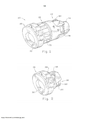
[015] Fig. 1 é uma vista em perspectiva de uma montagem de gargalo de entrada de sistema de combustível de veículo tendo um dispositivo que inibe troca de combustível no mesmo;[015] Fig. 1 is a perspective view of a vehicle fuel system entry neck assembly having a device that inhibits fuel exchange therein;
[016] Fig. 2 é uma vista em perspectiva de uma parte fragmentária, e mais especificamente a parte externa da montagem de gargalo de entrada de sistema de combustível mostrada na Fig. 1;[016] Fig. 2 is a perspective view of a fragmentary part, and more specifically the external part of the fuel system inlet neck assembly shown in Fig. 1;
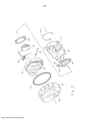
[017] Fig. 3 é uma vista explodida da parte fragmentária da montagem de gargalo de entrada mostrada na Fig. 2;[017] Fig. 3 is an exploded view of the fragmentary part of the inlet neck assembly shown in Fig. 2;
[018] Fig. 4 é uma vista em perspectiva de outra parte fragmentária, e mais especificamente a parte interna da montagem de gargalo de entrada de sistema de combustível mostrada na Fig. 1;[018] Fig. 4 is a perspective view of another fragmentary part, and more specifically the internal part of the fuel system inlet neck assembly shown in Fig. 1;
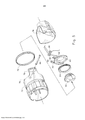
[019] Fig. 5 é uma vista explodida da parte fragmentária da montagem de gargalo de entrada mostrada na Fig. 4;[019] Fig. 5 is an exploded view of the fragmentary part of the inlet neck assembly shown in Fig. 4;
[020] Fig. 6 é uma vista em corte da montagem de gargalo de entrada de sistema de combustível de veículo mostrada na Fig. 1;[020] Fig. 6 is a sectional view of the vehicle fuel system intake neck assembly shown in Fig. 1;
[021] Fig. 7 é uma vista final da montagem de gargalo de entrada mostrada em uma condição travada;[021] Fig. 7 is a final view of the entry neck assembly shown in a locked condition;
[022] Fig. 8 é uma vista em perspectiva da montagem de gargalo de entrada em uma condição destravada;[022] Fig. 8 is a perspective view of the entry neck assembly in an unlocked condition;
[023] Fig. 9 é uma vista em perspectiva, parcialmente rompida e ilustrando um bico sendo inserido na montagem de gargalo de entrada;[023] Fig. 9 is a perspective view, partially broken and illustrating a nozzle being inserted in the entry neck assembly;
[024] Fig. 10 é uma vista final elevada da parte externa e da montagem de gargalo interna;[024] Fig. 10 is a final elevated view of the external part and the internal neck assembly;
[025] Fig. 11 é uma vista em perspectiva do atuador do dispositivo de inibição de troca de combustível; e[025] Fig. 11 is a perspective view of the actuator of the fuel exchange inhibition device; and
[026] Fig. 12 é uma vista elevada do atuador mostrado na Fig. 11.[026] Fig. 12 is an elevated view of the actuator shown in Fig. 11.
[027] Antes das modalidades da invenção ser explicadas em detalhes, deve ser entendido que a invenção não é limitada em sua aplicação aos detalhes de construção e os arranjos dos componentes estabelecidos na descrição a seguir ou ilustrados nos desenhos. A invenção é capaz de outras modalidades e de ser praticada ou ser realizada de diversos modos. Além disso, entende-se que a fraseologia e terminologia usadas aqui são para as finalidades de descrição e não devem ser consideradas como limitativas. O uso aqui de “incluir”, “compreender” e variações dos mesmos se destina a abranger os itens listados subsequentemente e equivalentes dos mesmos, assim como itens adicionais e equivalentes dos mesmos.[027] Before the modalities of the invention are explained in detail, it should be understood that the invention is not limited in its application to the details of construction and the arrangements of the components set out in the description below or illustrated in the drawings. The invention is capable of other modalities and can be practiced or carried out in different ways. In addition, it is understood that the phraseology and terminology used here are for the purpose of description and should not be considered as limiting. The use here of "include", "understand" and variations thereof is intended to cover the items listed subsequently and their equivalents, as well as additional items and equivalents thereof.
[028] Fazendo referência agora mais especificamente aos desenhos e às Figs. 1 e 2 em particular, uma montagem de gargalo de entrada de reabastecimento de sistema de combustível de veículo 20 está mostrada tendo um inibidor de troca de combustível 22 como uma parte da mesma para impedir a inserção de um bico de reabastecimento que é menor em diâmetro do que os bicos providos para o combustível de destino. A montagem de gargalo de entrada 20 está mostrada como um sistema de reabastecimento sem tampa tendo uma válvula de fechamento primária 24 e uma montagem de proteção de serviço externa sem tampa 28 26. Entretanto, aqueles versados na técnica irão prontamente reconhecer que o inibidor de troca de combustível 22 pode ser incorporado ao gargalo de entrada de um sistema de combustível de veículo tendo também uma tampa externa removível sobre o mesmo. A estrutura sem tampa mostrada é meramente um arranjo adequado em que o inibidor de troca de combustível pode ser usado de maneira vantajosa, porém não se destina a limitar aplicações e usos da presente invenção, nem o escopo das reivindicações que seguem.[028] Referring now more specifically to the drawings and Figs. 1 and 2 in particular, a vehicle fuel system refueling
[029] O inibidor de troca de combustível 22 está operavelmente posicionado entre a montagem de proteção de serviço externo 26 e a válvula de fechamento primária 24 e coopera de maneira estrutural com a válvula de fechamento primária 24 para possibilitar e inabilitar a abertura da válvula de fechamento primária 24 quando a válvula de fechamento 24 e a montagem de proteção de serviço externa 26 a serem descritas daqui por diante podem ser feitas de materiais resistentes a combustível adequados, incluindo diversos plásticos e metais que são bem conhecidos para aqueles versados na técnica.[029] The
[030] A montagem de proteção de serviço externa 26 (Fig. 3) inclui uma proteção de serviço 30, um corpo externo anular 32 e uma vedação 34. O corpo externo anular 32 prende pivotavelmente um portador de porta articulada de serviço 36 tendo orelhas 38, 40 mantidas para o corpo externo anular 32 através de um pino pivô 42 recebido em um canal 44 do corpo externo e em orifícios 46, 48 das orelhas 38, 40. O portador de porta articulada 36 segura uma porta articulada de serviço 50 e uma vedação de porta articulada 52. A proteção de serviço 30 define uma abertura 54 e um rebordo interno 56 (Fig. 6). Uma mola de porta articulada de serviço 58 impele o portador de porta articulada 36 em direção a uma posição fechada em que a porta articulada 50 está posicionada na abertura 54 e a vedação 52 está engatada contra o rebordo 56.[030] The external service guard assembly 26 (Fig. 3) includes a
[031] A válvula de fechamento primária 24 (Fig. 5) inclui um corpo em geral anular 70, uma vedação anular 72 e um guia de bico 74. O guia de bico 74 é recebido entre e engatado por abas 76,78 do corpo 70 e pode incluir saliências recebidas em janelas das abas para garantir a conexão do guia de bico 74 ao corpo anular 70. Um portador de porta articulada de válvula de fechamento primária 80 tendo orelhas 82, 84 é preso ao corpo 70 através de um pino pivô 86 recebido nos orifícios 88, 90 das orelhas 82, 84. O portador de porta articulada 80 prende uma porta articulada de válvula de fechamento primária 92 e uma vedação de porta articulada de válvula primária 94. Uma mola 96 impele a porta articulada 92 em direção a uma posição fechada em que a vedação 94 é mantida contra um rebordo 98 (Fig. 6).[031] The primary shut-off valve 24 (Fig. 5) includes a generally
[032] O inibidor de troca de combustível 22 inclui um atuador 110 e um guia de bico 112 que leva ao atuador 110. Na modalidade exemplar mostrada, o guia de bico 112 é uma projeção substancialmente semicilíndrica a montante do atuador 110. O atuador 110 inclui uma seção de ponte 114 conectada a uma cúpula 116.[032] The
[033] O atuador 110 (Figs. 11 e 12) ainda inclui asas laterais 118, 120 que se estendem a partir de extremidades opostas da seção de ponte 114. As asas 118, 120, cada uma inclui uma pluralidade de seções ou segmentos de asa. Na modalidade exemplar mostrada, a asa 118 inclui segmentos de asa 122, 124 e a asa 120 inclui segmentos de asa 126, 128. Áreas de conexão relativamente espessa são providas entre a seção de ponte 114 e cada asa 118 e 120 e entre segmentos de asa adjacentes 122, 124 e 126, 128 compreendendo as asas. Em conformidade, uma área de conexão relativamente espessa 130 é provida entre a seção de ponte 114 e o segmento de asa 122, e um espaço radial, exteriormente fechado 131 é provido entre a seção de ponte 114 e o segmento de asa 122. Uma área de conexão relativamente espessa 132 e um espaço radial exteriormente fechado 133 são providos entre o segmento de asa 122 e o segmento de asa 124. Uma área de conexão relativamente espessa 134 e um espaço radial exteriormente fechado 135 são providos entre a seção de ponte 114 e o segmento de asa 126, e uma área de conexão relativamente espessa 136 e um espaço radial exteriormente fechado 137 são providos entre o segmento de asa 126 e o segmento de asa 128.[033] Actuator 110 (Figs. 11 and 12) further includes
[034] Braços dirigidos para dentro 138, 140 são providos nas extremidades distais das asas 118, 120, respectivamente. Os braços 138, 140 engatam e operam com a porta articulada de válvula de fechamento primária 92, conforme será descrito subsequentemente aqui. Uma mola em arco 142 circunda o atuador 110 e engata os segmentos de asa distais 124, 128 das asas 118, 120. A mola em arco 142 constrin- ge as asas 118, 120 e resiste à expansão externa das asas.[034] Inwardly directed
[035] As extremidades distais ou remotas das asas 118, 120 são livres e não conectadas entre si ou a outra estrutura dentro do atuador que não seja através da interconexão de mola em arco 142. Consequentemente, as áreas de conexão relativamente finas e os espaços radiais descritos acima permitem que as asas 118, 120 se flexionem e se curvem mediante a pressão exercida a partir de um bico que é inserido durante uma operação de reabastecimento quando a pressão exercida pelo mesmo é suficiente para superar a resistência provida pela mola em arco 142. Ausente tal pressão para a expansão, as asas 118, 120 são mantidas em uma condição constrita pela mola em arco 142.[035] The distal or remote ends of the
[036] A porta articulada de válvula de fechamento primária 92 define áreas rebaixadas 150, 15 em lados opostos de e atrás de um poste 154 no lado inferior da porta articulada 92. Na condição fechada ou constrita do atuador 110, os braços 138,140 se projetam através das áreas rebaixadas 150, 152 e atrás do poste 154. Consequentemente, com o atuador 110 na condição constrita, os braços 138, 140 engatam a porta articulada 92 e travam a porta articulada na condição fechada. Uma expansão externa suficiente de ambas as asas 118 e 120 move cada braço 138, 140 externamente a partir de trás do poste 154, deste modo permitindo que a porta articulada de válvula de fechamento primário se mova.[036] The primary shut-off valve hinged 92 defines recessed
[037] Um grampo 160 e pinos 162, 164 podem ser usados para fixar e manter o inibidor de troca de combustível 22 dentro do conjunto. Por meio da disposição de um pino na seção de ponte 114 em uma posição fixa, as asas 118, 120 podem se mover independentemente. O movimento de uma asa não provoca o movimento da outra asa.[037] A
[038] As asas 118, 120 definem uma área aberta expansível nas suas bordas radialmente internas. A área aberta definida entre as bordas internas das asas 118, 120 definem uma passagem axial expansível através do atuador 110, que é expandido pela deflexão externa das asas. Em um estado relaxado do atuador 110, sob a influência da mola em arco 142, a abertura definida é de diâmetro menor do que o diâmetro do menor bico de reabastecimento aceitável a ser recebido no sistema de combustível e é maior do que os diâmetros de bicos de reabastecimento para combustíveis inaceitáveis que são impedidos de entrar completamente no conjunto de gargalo de entrada 20.[038] The
[039] Como ilustrado pela linha tracejada na figura 10, que é designada pelonúmero de referência 16, um objeto de um determinado diâmetro ou de diâmetro inferior pode ser inserido sem expandir as asas, e um objeto tal como um bico de reabastecimento 170 (figura 9) do diâmetro prescrito ou diâmetro superior pode ser empurrado além do atuador 110 somente pela deflexão das asas 118, 120 para fora. Quando as asas são defletidas para fora a uma distância suficiente, os braços 128, 140 desengatam da porta articulada de válvula de fechamento primário 92 e permitem que a porta se mova. Consequentemente, se um bico de reabastecimento menor do que o diâmetro requerido for inserido, as asas não são defletidas para fora, os braços 138, 140 permanecem engatados com a porta articulada de válvula de fechamento primário 92 e a porta permanece em uma condição travada. O bico menor que o diâmetro requerido não pode passar através e além do atuador 110.Por outro lado, se um bico do diâmetro prescrito ou maior for inserido, as asas 118, 120 são defletidas para foram juntamente com os braços 138, 140 que desengatam da porta articulada de válvula de fechamento primário 92. A porta é destravada e deixada se mover. Força adicional na inserção do bico move a porta articulada para cima e para longe, desta forma permitindo que o bico passe através da abertura expandida no atuador 110 e além da válvula de fechamento primário.[039] As illustrated by the dashed line in figure 10, which is designated by reference number 16, an object of a certain diameter or smaller diameter can be inserted without expanding the wings, and an object such as a refueling nozzle 170 (figure 9) of the prescribed diameter or larger diameter can be pushed beyond the
[040] Como pode ser visto na figura 10, as asas 118, 120 juntamente com a seção de ponte 114 geralmente definem uma estrutura em forma de U invertido que é aberta no lado inferior e possui uma porção fixa de seção de ponte 114 substancialmente oposta à abertura definida entre as extremidades distais das asas 118, 120. Consequentemente, a força a montante ou a jusante a partir de um bico de diâmetro insuficiente não provoca o espalhamento ou expansão dos segmentos de asa, e a porta articulada de válvula de fechamento primário permanece em uma condição fechada e travada. Além disso, uma força lateral exercida por um bico de diâmetro insuficiente também falha em destravar a porta articulada de válvula de fechamento primário. Se o bico menor que o diâmetro requerido for pressionado lateralmente contra a asa 118 ou contra a asa 120, a asa contra a qual a força exercida pode ser levada a se mover lateralmente; contudo mesmo se o braço da asa for movido suficientemente para desengatar da porta articulada de válvula de fechamento primário 92, a outra asa e o braço conectado aa mesma irão permanecer na posição para dentro ou constrita, e a porta articulada de válvula de fechamento primário irá per- manecer fechada e travada.[040] As can be seen in figure 10, the
[041] Os vários segmentos de asa 122, 124, 126, 128 podem ser providos com superfícies voltadas para cima que formam ângulos para a jusante na direção radialmente interna da sua periferia externa para o diâmetro interno definido pelas bordas internas dos segmentos de asa. Consequentemente, à medida que o bico de reabastecimento é inserido, o bico é naturalmente direcionado na direção da abertura entre as asas do atuador para uma posição geralmente centralizada, de modo que a inserção continuada de um bico de diâmetro suficiente opera contra ambas as asas uniformemente. Superfícies chanfradas e/ou angulares podem se providas através do conjunto para facilitar e direcionar a inserção de um bico de reabastecimento.[041] The
[042] Durante uma operação de reabastecimento, um bico de reabastecimentoé inserido através da montagem de proteção de serviço 26 pela força exercida contra a porta articulada de serviço 50. À medida que o bico é inserido, o portador de porta articulada de serviço 36 é pivotado sobre o pino pivô para permitir que o bico passe através da abertura 54. À medida que a extremidade do bico se aproxima da porta articulada de válvula de fechamento primário 92, a porta articulada travada é uma obstrução móvel para a inserção adicional do bico. O atuador 110 discrimina entre os diâmetros de bico menores que o diâmetro aceitável prescrito e aqueles tão grandes quanto ou maiores que o diâmetro aceitável prescrito. Bicos de diâmetro menores que o aceitável não engatam e expandem os segmentos de asa 122, 124, 12,6, 128 suficientemente para desengatar ambos os braços 138,140 da porta articulada de válvula de fechamento primário 92, e a porta articulada permanece fechada. Um bico de diâmetro pelo menos tão grande quanto o diâmetro mínimo aceitável engata e expande a abertura através do atuador pela movimentação dos segmentos de asa 122, 1124, 126, 128 para fora suficientemente para desengatar os braços da porta articulada de válvula de fechamento primário 92, pelo que destrava a porta ar- ticulada e permite que ela se mova. À medida que o bico é inserido adicionalmente, a porta articulada de válvula de fechamento primário é defletida suficientemente de modo que a extremidade do bico possa ser inserida através do mesmo e a operação de reabastecimento completada. Mediante conclusão, quando o bico é removido, a porta articulada de válvula de fechamento primário 92 e a porta articulada de entrada de serviço 50 cada qual retorna às suas posições fechadas mediante a influência das molas de porta articulada respectivas 58 e 96.[042] During a refueling operation, a refueling nozzle is inserted through the
[043] Consequentemente, a estrutura é provida para permitir a inserção de bicos que possuem diâmetros em ou acima do diâmetro mínimo requerido, enquanto se excluem os bicos que possuem diâmetros menores. A estrutura de atuador 110 não abrirá um bico menor para permitir que um bico menor entre, ainda que uma força seja aplicada contra alguns, mas não a todos os segmentos de asa. As formas multidirecionais requeridas são aplicadas quando um bico de um diâmetro maior que a abertura estreitada for inserido, mas não são alcançadas se um bico menor que a abertura estreitada for inserido, mesmo se o bico menor for forçado contra alguns dos segmentos de asa 122, 124, 126, 128.[043] Consequently, the structure is provided to allow the insertion of nozzles that have diameters at or above the required minimum diameter, while excluding nozzles that have smaller diameters.
[044] Variações e modificações do acima exposto estão dentro do escopo da presente invenção. Será entendido que a invenção descrita e definida aqui se estende a todas as combinações alternativas de duas ou mais características individuais mencionadas ou evidentes do texto e/ou dos desenhos. Todas as combinações diferentes compreendem vários aspectos alternativos da presente invenção. As concretizações descritas aqui explicam os melhores modos conhecidos para praticar a invenção e permitirão àqueles versados na técnica utilizar a invenção. As reivindicações a seguir incluem concretizações alternativas até o limite permitido pela técnica anterior.[044] Variations and modifications of the above are within the scope of the present invention. It will be understood that the invention described and defined here extends to all alternative combinations of two or more individual characteristics mentioned or evident from the text and / or drawings. All of the different combinations comprise several alternative aspects of the present invention. The embodiments described here explain the best known ways to practice the invention and will allow those skilled in the art to use the invention. The following claims include alternative embodiments to the extent permitted by the prior art.
[045] Várias características da invenção são definidas nas seguintes reivindicações.[045] Various features of the invention are defined in the following claims.
Claims (15)
Applications Claiming Priority (3)
| Application Number | Priority Date | Filing Date | Title |
|---|---|---|---|
| US15961409P | 2009-03-12 | 2009-03-12 | |
| US61/159.614 | 2009-03-12 | ||
| PCT/US2010/024720 WO2010104661A1 (en) | 2009-03-12 | 2010-02-19 | Mis-fuel inhibitor |
Publications (2)
| Publication Number | Publication Date |
|---|---|
| BRPI1009551A2 BRPI1009551A2 (en) | 2018-03-13 |
| BRPI1009551B1 true BRPI1009551B1 (en) | 2021-02-02 |
Family
ID=42238242
Family Applications (1)
| Application Number | Title | Priority Date | Filing Date |
|---|---|---|---|
| BRPI1009551-9A BRPI1009551B1 (en) | 2009-03-12 | 2010-02-19 | inhibitor for a vehicle fuel system refueling inlet set and vehicle fuel system inlet bottleneck set |
Country Status (7)
| Country | Link |
|---|---|
| US (1) | US8714214B2 (en) |
| EP (1) | EP2406095B1 (en) |
| JP (1) | JP5596712B2 (en) |
| KR (1) | KR101717185B1 (en) |
| CN (1) | CN102348569B (en) |
| BR (1) | BRPI1009551B1 (en) |
| WO (1) | WO2010104661A1 (en) |
Families Citing this family (47)
| Publication number | Priority date | Publication date | Assignee | Title |
|---|---|---|---|---|
| US8555937B2 (en) * | 2008-09-11 | 2013-10-15 | Honda Motor Co., Ltd. | Structure for fuel filling opening of automobile |
| DE102011009745B4 (en) * | 2011-01-28 | 2012-09-13 | Kautex Textron Gmbh & Co. Kg | Filler neck for a secondary fluid tank |
| FR2975048B1 (en) * | 2011-05-12 | 2013-06-28 | Itw De France | HEAD FOR FUEL FILLING TUBE OF A VEHICLE TANK |
| JP5370420B2 (en) * | 2011-06-10 | 2013-12-18 | トヨタ自動車株式会社 | Fuel tank fueling part structure |
| US10000117B2 (en) | 2012-02-17 | 2018-06-19 | Stant Usa Corp. | Filler neck closure assembly |
| AU2013243950A1 (en) | 2012-04-02 | 2014-10-30 | Moderna Therapeutics, Inc. | Modified polynucleotides |
| AU2013243949A1 (en) | 2012-04-02 | 2014-10-30 | Moderna Therapeutics, Inc. | Modified polynucleotides for the production of biologics and proteins associated with human disease |
| DE112013001029B4 (en) * | 2012-05-17 | 2018-05-09 | Illinois Tool Works Inc. | Fuel nozzle-receiving assembly |
| JP5907028B2 (en) * | 2012-09-28 | 2016-04-20 | 豊田合成株式会社 | Fuel tank opening and closing device |
| US8950615B2 (en) * | 2012-12-28 | 2015-02-10 | Ford Global Technologies, Llc | Vehicle fueling apparatus |
| CN105073472B (en) * | 2013-02-27 | 2019-05-03 | 伊利诺斯工具制品有限公司 | Improper fuel nozzle insertion inhibits component |
| WO2014172087A1 (en) * | 2013-04-16 | 2014-10-23 | Illinois Tool Works Inc. | Improper fuel nozzle insertion-inhibiting system |
| KR101417637B1 (en) * | 2013-05-08 | 2014-07-08 | 현대자동차주식회사 | Filler neck device for preventing fuel from mixing |
| US20160194368A1 (en) | 2013-09-03 | 2016-07-07 | Moderna Therapeutics, Inc. | Circular polynucleotides |
| AU2014315287A1 (en) | 2013-09-03 | 2015-03-12 | Moderna Therapeutics, Inc. | Chimeric polynucleotides |
| JP6231843B2 (en) | 2013-10-11 | 2017-11-15 | 株式会社アステア | Misfueling prevention device |
| FR3011778A1 (en) * | 2013-10-14 | 2015-04-17 | Illinois Tool Works | HEAD FOR FUEL FILLING TUBE OF A VEHICLE TANK PROVIDED WITH A FITTING ASSEMBLY |
| DK3071696T3 (en) | 2013-11-22 | 2019-10-07 | Mina Therapeutics Ltd | C / EBP ALFA SHORT ACTIVATION RNA COMPOSITIONS AND METHODS OF USE |
| WO2016014846A1 (en) | 2014-07-23 | 2016-01-28 | Moderna Therapeutics, Inc. | Modified polynucleotides for the production of intrabodies |
| DE102014111834A1 (en) | 2014-08-19 | 2016-02-25 | Illinois Tool Works Inc. | Filling device for a fuel tank |
| DE102015107681A1 (en) | 2015-05-15 | 2016-11-17 | Illinois Tool Works Inc. | filler pipe |
| JP6468976B2 (en) * | 2015-09-09 | 2019-02-13 | 株式会社ニフコ | Filling port device |
| JP6419054B2 (en) * | 2015-10-09 | 2018-11-07 | 株式会社ニフコ | Filling port device |
| US10081241B2 (en) * | 2015-12-10 | 2018-09-25 | Curtis Alan Roys | Diesel fuel guard |
| SI3394093T1 (en) | 2015-12-23 | 2022-05-31 | Modernatx, Inc. | Methods of using ox40 ligand encoding polynucleotides |
| US20190241658A1 (en) | 2016-01-10 | 2019-08-08 | Modernatx, Inc. | Therapeutic mRNAs encoding anti CTLA-4 antibodies |
| US9987922B2 (en) * | 2016-08-16 | 2018-06-05 | Ford Global Technologies, Llc | Capless refueling mechanism |
| WO2018104540A1 (en) | 2016-12-08 | 2018-06-14 | Curevac Ag | Rnas for wound healing |
| US10543746B2 (en) | 2017-04-04 | 2020-01-28 | Illinois Tool Works Inc. | Dual nozzle-receiving assembly |
| US10640358B2 (en) | 2017-06-21 | 2020-05-05 | Ford Global Technologies, Llc | Capless refill adapter for a fluid refilling system |
| EP3679139B1 (en) | 2017-09-08 | 2022-11-02 | MiNA Therapeutics Limited | Stabilized hnf4a sarna compositions and methods of use |
| EP3679140B1 (en) | 2017-09-08 | 2022-11-16 | MiNA Therapeutics Limited | Stabilized cebpa sarna compositions and methods of use |
| JP6881339B2 (en) * | 2018-01-31 | 2021-06-02 | 豊田合成株式会社 | Refueling device |
| US10836248B2 (en) * | 2018-02-21 | 2020-11-17 | Ford Global Technologies, Llc | Nozzle guide for vehicle refueling adapter |
| US11566246B2 (en) | 2018-04-12 | 2023-01-31 | Mina Therapeutics Limited | SIRT1-saRNA compositions and methods of use |
| KR102105986B1 (en) * | 2018-06-12 | 2020-05-06 | 코리아에프티 주식회사 | Filler tube and filler neck having the same |
| US20220211740A1 (en) | 2019-04-12 | 2022-07-07 | Mina Therapeutics Limited | Sirt1-sarna compositions and methods of use |
| DE202019105565U1 (en) * | 2019-10-09 | 2021-01-21 | Gerdes Gmbh | Tank filler cap for a fuel tank |
| KR102174927B1 (en) * | 2019-10-28 | 2020-11-06 | 삼보모터스주식회사 | Capless misfuelling prevention device |
| US11597269B2 (en) | 2019-11-13 | 2023-03-07 | Toyoda Gosei Co., Ltd. | Fuel device |
| KR102244946B1 (en) * | 2020-03-24 | 2021-04-27 | 삼보모터스주식회사 | Fuel filler neck device of vehicle fuel system |
| GB2603454A (en) | 2020-12-09 | 2022-08-10 | Ucl Business Ltd | Novel therapeutics for the treatment of neurodegenerative disorders |
| JP2024511092A (en) | 2021-03-26 | 2024-03-12 | ミナ セラピューティクス リミテッド | TMEM173saRNA composition and method of use |
| WO2023099884A1 (en) | 2021-12-01 | 2023-06-08 | Mina Therapeutics Limited | Pax6 sarna compositions and methods of use |
| GB202117758D0 (en) | 2021-12-09 | 2022-01-26 | Ucl Business Ltd | Therapeutics for the treatment of neurodegenerative disorders |
| WO2023161350A1 (en) | 2022-02-24 | 2023-08-31 | Io Biotech Aps | Nucleotide delivery of cancer therapy |
| WO2023170435A1 (en) | 2022-03-07 | 2023-09-14 | Mina Therapeutics Limited | Il10 sarna compositions and methods of use |
Family Cites Families (15)
| Publication number | Priority date | Publication date | Assignee | Title |
|---|---|---|---|---|
| DE4039269C1 (en) | 1990-12-08 | 1992-02-06 | Mercedes-Benz Aktiengesellschaft, 7000 Stuttgart, De | Self-closing fuel tank seal for filling tube - has lock automatically securing closure cap on filling aperture sealing seat |
| DE4242598C2 (en) * | 1992-12-16 | 1995-11-16 | Temtec Fahrzeugtechnik Entwicklungsgesellschaft Mbh | Closure for closing the mouth of a nozzle |
| FR2710720B1 (en) | 1993-09-29 | 1995-11-24 | Journee Paul Sa | Filling head for a motor vehicle fuel tank. |
| FR2710721B1 (en) | 1993-09-29 | 1995-11-24 | Journee Paul Sa | Filling head for a filling pipe of a motor vehicle tank. |
| DE10126207A1 (en) | 2001-05-30 | 2003-01-16 | Bayerische Motoren Werke Ag | Motor vehicle fuel tank with a filler neck for holding a fuel nozzle for diesel fuel |
| DE10139665A1 (en) | 2001-08-11 | 2003-02-20 | Bayerische Motoren Werke Ag | Motor vehicle fuel tank with a filler neck for holding a fuel nozzle for diesel fuel |
| DE102004002994B3 (en) * | 2004-01-19 | 2005-09-22 | Itw Automotive Products Gmbh & Co. Kg | Filler neck for filling fuel into a vehicle tank |
| US7302977B2 (en) | 2004-09-30 | 2007-12-04 | Stant Manufacturing Inc. | Fuel-dispensing nozzle inhibitor |
| US6968874B1 (en) | 2004-10-07 | 2005-11-29 | Martinrea Industries, Inc. | Capless automotive fueling system |
| GB2421499A (en) * | 2004-12-21 | 2006-06-28 | Nathan Phillips | A refuelling aid to prevent improper fuel being used |
| US7665493B2 (en) * | 2005-02-10 | 2010-02-23 | Stant Manufacturing Inc. | Fuel-dispensing nozzle inhibitor |
| US7967041B2 (en) * | 2007-07-19 | 2011-06-28 | Stant Usa Corp. | Fuel-dispensing nozzle inhibitor |
| EP2093090B1 (en) * | 2008-02-21 | 2014-07-23 | Stant USA Corp. | Fuel-dispensing nozzle inhibitor |
| JP5206370B2 (en) * | 2008-11-28 | 2013-06-12 | 豊田合成株式会社 | Fuel tank opening and closing device |
| JP5370420B2 (en) * | 2011-06-10 | 2013-12-18 | トヨタ自動車株式会社 | Fuel tank fueling part structure |
-
2010
- 2010-02-19 WO PCT/US2010/024720 patent/WO2010104661A1/en active Application Filing
- 2010-02-19 CN CN201080011474.6A patent/CN102348569B/en active Active
- 2010-02-19 KR KR1020117021246A patent/KR101717185B1/en active IP Right Grant
- 2010-02-19 US US13/255,845 patent/US8714214B2/en active Active
- 2010-02-19 JP JP2011554066A patent/JP5596712B2/en active Active
- 2010-02-19 EP EP10705070.0A patent/EP2406095B1/en active Active
- 2010-02-19 BR BRPI1009551-9A patent/BRPI1009551B1/en active IP Right Grant
Also Published As
| Publication number | Publication date |
|---|---|
| US8714214B2 (en) | 2014-05-06 |
| WO2010104661A1 (en) | 2010-09-16 |
| KR101717185B1 (en) | 2017-03-16 |
| US20120024422A1 (en) | 2012-02-02 |
| EP2406095B1 (en) | 2013-11-06 |
| JP5596712B2 (en) | 2014-09-24 |
| BRPI1009551A2 (en) | 2018-03-13 |
| EP2406095A1 (en) | 2012-01-18 |
| CN102348569B (en) | 2015-08-19 |
| KR20110129893A (en) | 2011-12-02 |
| JP2012520204A (en) | 2012-09-06 |
| CN102348569A (en) | 2012-02-08 |
Similar Documents
| Publication | Publication Date | Title |
|---|---|---|
| BRPI1009551B1 (en) | inhibitor for a vehicle fuel system refueling inlet set and vehicle fuel system inlet bottleneck set | |
| EP2994329B1 (en) | Fuel-dispensing nozzle inhibitor | |
| US8726950B2 (en) | Mis-fuel inhibitor | |
| EP3177532B1 (en) | Filler neck closure assembly | |
| US20160009173A1 (en) | Improper fuel nozzle insertion-inhibiting assembly | |
| BR112016013298B1 (en) | FUEL SYSTEM WITHOUT COVER | |
| US10081241B2 (en) | Diesel fuel guard | |
| WO2008024571A2 (en) | Automotive fuel filling system | |
| US9522594B2 (en) | Improper fuel nozzle insertion-inhibiting system | |
| EP3237245B1 (en) | Capless automotive fueling system with miss-fuel inhibitor | |
| JP6486183B2 (en) | Refueling system and assembly method thereof | |
| US11142063B2 (en) | Filler neck for filling an operating substance or additive into a vehicle tank by means of a fuel pump nozzle | |
| WO2020241376A1 (en) | Reserve tank | |
| KR20090060906A (en) | Shut-off valve for fuel tank |
Legal Events
| Date | Code | Title | Description |
|---|---|---|---|
| B06F | Objections, documents and/or translations needed after an examination request according [chapter 6.6 patent gazette] | ||
| B06U | Preliminary requirement: requests with searches performed by other patent offices: procedure suspended [chapter 6.21 patent gazette] | ||
| B06A | Notification to applicant to reply to the report for non-patentability or inadequacy of the application [chapter 6.1 patent gazette] | ||
| B09A | Decision: intention to grant [chapter 9.1 patent gazette] | ||
| B16A | Patent or certificate of addition of invention granted |
Free format text: PRAZO DE VALIDADE: 10 (DEZ) ANOS CONTADOS A PARTIR DE 02/02/2021, OBSERVADAS AS CONDICOES LEGAIS. |