BRPI0911965B1 - APPARATUS AND METHOD TO CONTROL BLOOD FLOW THROUGH AN INTRAVENOUS CATHETER - Google Patents
APPARATUS AND METHOD TO CONTROL BLOOD FLOW THROUGH AN INTRAVENOUS CATHETER Download PDFInfo
- Publication number
- BRPI0911965B1 BRPI0911965B1 BRPI0911965-5A BRPI0911965A BRPI0911965B1 BR PI0911965 B1 BRPI0911965 B1 BR PI0911965B1 BR PI0911965 A BRPI0911965 A BR PI0911965A BR PI0911965 B1 BRPI0911965 B1 BR PI0911965B1
- Authority
- BR
- Brazil
- Prior art keywords
- outer shell
- catheter
- fact
- catheter adapter
- side edge
- Prior art date
Links
Images


Classifications
-
- A—HUMAN NECESSITIES
- A61—MEDICAL OR VETERINARY SCIENCE; HYGIENE
- A61M—DEVICES FOR INTRODUCING MEDIA INTO, OR ONTO, THE BODY; DEVICES FOR TRANSDUCING BODY MEDIA OR FOR TAKING MEDIA FROM THE BODY; DEVICES FOR PRODUCING OR ENDING SLEEP OR STUPOR
- A61M25/00—Catheters; Hollow probes
- A61M25/01—Introducing, guiding, advancing, emplacing or holding catheters
- A61M25/06—Body-piercing guide needles or the like
- A61M25/0606—"Over-the-needle" catheter assemblies, e.g. I.V. catheters
-
- A—HUMAN NECESSITIES
- A61—MEDICAL OR VETERINARY SCIENCE; HYGIENE
- A61M—DEVICES FOR INTRODUCING MEDIA INTO, OR ONTO, THE BODY; DEVICES FOR TRANSDUCING BODY MEDIA OR FOR TAKING MEDIA FROM THE BODY; DEVICES FOR PRODUCING OR ENDING SLEEP OR STUPOR
- A61M39/00—Tubes, tube connectors, tube couplings, valves, access sites or the like, specially adapted for medical use
- A61M39/02—Access sites
- A61M39/06—Haemostasis valves, i.e. gaskets sealing around a needle, catheter or the like, closing on removal thereof
- A61M39/0606—Haemostasis valves, i.e. gaskets sealing around a needle, catheter or the like, closing on removal thereof without means for adjusting the seal opening or pressure
-
- A—HUMAN NECESSITIES
- A61—MEDICAL OR VETERINARY SCIENCE; HYGIENE
- A61M—DEVICES FOR INTRODUCING MEDIA INTO, OR ONTO, THE BODY; DEVICES FOR TRANSDUCING BODY MEDIA OR FOR TAKING MEDIA FROM THE BODY; DEVICES FOR PRODUCING OR ENDING SLEEP OR STUPOR
- A61M39/00—Tubes, tube connectors, tube couplings, valves, access sites or the like, specially adapted for medical use
- A61M2039/0036—Tubes, tube connectors, tube couplings, valves, access sites or the like, specially adapted for medical use characterised by a septum having particular features, e.g. having venting channels or being made from antimicrobial or self-lubricating elastomer
-
- A—HUMAN NECESSITIES
- A61—MEDICAL OR VETERINARY SCIENCE; HYGIENE
- A61M—DEVICES FOR INTRODUCING MEDIA INTO, OR ONTO, THE BODY; DEVICES FOR TRANSDUCING BODY MEDIA OR FOR TAKING MEDIA FROM THE BODY; DEVICES FOR PRODUCING OR ENDING SLEEP OR STUPOR
- A61M39/00—Tubes, tube connectors, tube couplings, valves, access sites or the like, specially adapted for medical use
- A61M39/02—Access sites
- A61M39/06—Haemostasis valves, i.e. gaskets sealing around a needle, catheter or the like, closing on removal thereof
- A61M2039/062—Haemostasis valves, i.e. gaskets sealing around a needle, catheter or the like, closing on removal thereof used with a catheter
-
- A—HUMAN NECESSITIES
- A61—MEDICAL OR VETERINARY SCIENCE; HYGIENE
- A61M—DEVICES FOR INTRODUCING MEDIA INTO, OR ONTO, THE BODY; DEVICES FOR TRANSDUCING BODY MEDIA OR FOR TAKING MEDIA FROM THE BODY; DEVICES FOR PRODUCING OR ENDING SLEEP OR STUPOR
- A61M39/00—Tubes, tube connectors, tube couplings, valves, access sites or the like, specially adapted for medical use
- A61M39/02—Access sites
- A61M39/06—Haemostasis valves, i.e. gaskets sealing around a needle, catheter or the like, closing on removal thereof
- A61M2039/0633—Haemostasis valves, i.e. gaskets sealing around a needle, catheter or the like, closing on removal thereof the seal being a passive seal made of a resilient material with or without an opening
- A61M2039/064—Slit-valve
Abstract
dispositivo de controle de cateter sanguíneo intravenoso. um aparelho(114) para controlar fluxo de sangue através de um cateter intravenoso (100) de acordo com a presente invenção pode incluir um involucro externo helicoidal substancialmente flexível e uma porcão de válvula interna formada no mesmo. a porção de válvula interna pode ser configurada para abrir sob pressão o involucro externo helicoidal substancialmente flexível. em algumas modalidades, a porção de válvula interna pode incluir porções correspondentes as quais substancialmente se alinham para proporcionar escoamento de fluido entre as mesmas. comprimir o involucro externo helicoidal substancialmente flexível, por exemplo, ao inserir um dispositivo luer em um adaptador de cateter contendo o involucro externo substancialmente flexível, pode fazer com que as porções correspondentes se desalinhem, deste modo criando um trajeto de fluido.control device for intravenous blood catheter. an apparatus (114) for controlling blood flow through an intravenous catheter (100) according to the present invention can include a substantially flexible helical outer shell and an internal valve portion formed thereon. the inner valve portion may be configured to open the substantially flexible helical outer shell under pressure. in some embodiments, the inner valve portion may include corresponding portions which substantially align to provide fluid flow between them. compressing the substantially flexible helical outer casing, for example, by inserting a luer device into a catheter adapter containing the substantially flexible outer casing, can cause the corresponding portions to misalign, thereby creating a fluid path.
Description
A presente descrição se refere em geral a conjuntos médicos para a administração de fluido, e mais particularmente a conjuntos de cateteres intravenosos de sistema fechado que reduzem um potencial de exposição de sangue durante inserção e uso.The present description relates in general to medical sets for fluid delivery, and more particularly to closed system intravenous catheter sets that reduce a potential for blood exposure during insertion and use.
A inserção de um cateter intravenoso na corrente sanguínea do paciente é um dos procedimentos mais comumente realizados atualmente em ambientes de cuidados com a saúde. Os referidos cateteres são amplamente usados para infundir fluidos, tal como solu- ção salina, diversos medicamentos, e/ou nutrição parenteral total em um paciente. Os mes- mos podem também ser usados para retirar sangue a partir de um paciente, e/ou monitorar os diversos parâmetros do sistema vascular do paciente.Inserting an intravenous catheter into the patient's bloodstream is one of the most commonly performed procedures in health care settings today. Said catheters are widely used to infuse fluids, such as saline, various medications, and / or total parenteral nutrition in a patient. The same can also be used to draw blood from a patient, and / or to monitor the various parameters of the patient's vascular system.
Apesar de sua prevalência e utilidade em ambientes de cuidados com a saúde, os procedimentos usados para inserção de cateter intravenoso apresenta significante risco pa- ra a saúde dos profissionais de cuidados da saúde que os realizam. Particularmente, os pro- fissionais de cuidados da saúde estão em um grande risco de contrair hepatite virai, Vírus da Imunodeficiência Humana ("HIV"), o vírus que ocasiona o Vírus da Deficiência Autoimune ("AIDS"), e outras doenças infecciosas veiculadas pelo sangue. O referido risco é maior na medida em que a inserção de cateter intravenoso requer a desmontagem da agulha de in- trodução a partir do adaptador de cateter uma vez que o cateter é adequadamente posicio- nado dentro da corrente sanguínea do paciente. O referido processo requer um alto nível de destreza e manipulação física, com um maior risco associado de exposição ao sangue e patógenos do sangue.Despite its prevalence and usefulness in healthcare environments, the procedures used for insertion of intravenous catheters present a significant risk to the health of the healthcare professionals who perform them. In particular, health care professionals are at a great risk of contracting viral hepatitis, Human Immunodeficiency Virus ("HIV"), the virus that causes the Autoimmune Deficiency Virus ("AIDS"), and other infectious diseases carried by blood. This risk is greater in that the insertion of an intravenous catheter requires disassembly of the insertion needle from the catheter adapter once the catheter is properly positioned into the patient's bloodstream. This process requires a high level of dexterity and physical manipulation, with an increased risk associated with exposure to blood and blood pathogens.
Para se introduzir um cateter IV em um paciente, um cateter sobre-a-agulha pode ser montado sobre uma agulha de introdução de orifício oco dotada de uma ponta distai afi- ada. A superfície interna do cateter pode engatar apertadamente à superfície externa da agulha para evitar cateter peelback e facilitar a inserção do cateter em um vaso sanguíneo. A ponta da agulha de introdução pode se estender adiante da ponta distal do cateter para permitir a inserção do cateter em um ângulo raso através da pele do paciente e em um vaso sanguíneo.To insert an IV catheter into a patient, an over-the-needle catheter can be mounted on a hollow orifice introduction needle with a sharp distal tip. The inner surface of the catheter can tightly engage the outer surface of the needle to avoid peelback catheter and facilitate insertion of the catheter into a blood vessel. The tip of the introducing needle can extend in front of the distal tip of the catheter to allow the catheter to be inserted at a shallow angle through the patient's skin and into a blood vessel.
Para se verificar o posicionamento adequado da agulha e cateter no vaso sanguí- neo, o médico pode confirmar a presença de sangue de "refluxo"em uma câmara de refluxo associada com o conjunto de cateter e agulha. Uma vez que o posicionamento adequado é inicialmente confirmado, o médico pode então remover a agulha a partir do cateter e aplicar pressão ao vaso sanguíneo para obstruir o vaso, deste modo controlando fluxo de sangue adicional dentro do conjunto de cateter. A referida técnica, entretanto, é imprecisa e pode resultar na saída de sangue a partir do tubo de cateter que sai do vaso sanguíneo através do adaptador de cateter, deste modo comprometendo a esterilidade do trajeto de fluido e potencialmente expondo o trabalhador de cuidado da saúde ao sangue e patógenos do san- gue.To check the proper positioning of the needle and catheter in the blood vessel, the doctor can confirm the presence of "reflux" blood in a reflux chamber associated with the catheter and needle assembly. Once proper placement is initially confirmed, the doctor can then remove the needle from the catheter and apply pressure to the blood vessel to obstruct the vessel, thereby controlling additional blood flow within the catheter assembly. The said technique, however, is inaccurate and can result in blood coming out of the catheter tube that exits the blood vessel through the catheter adapter, thereby compromising the sterility of the fluid path and potentially exposing the healthcare worker blood and blood pathogens.
A necessidade de aplicar pressão digital ao vaso sanguíneo após a inserção do ca- teter também deixa o trabalhador de cuidado da saúde com apenas uma mão disponível para manipular o conjunto de inserção de cateter conforme necessário para remover a agu- lha e conectar o adaptador de cateter ao conjunto de administração. Esta necessidade au- menta ainda o potencial de erro humano resultando em exposição de sangue e danos rela- cionados a isto.The need to apply digital pressure to the blood vessel after inserting the catheter also leaves the healthcare worker with only one hand available to manipulate the catheter insertion set as needed to remove the needle and connect the adapter. catheter to the administration set. This need further increases the potential for human error resulting in blood exposure and related damage.
Finalmente, a prática típica de inserção de cateter requer que o cateter seja ainda avançado para dentro do vaso sanguíneo com a retirada da agulha a partir do mesmo. Em- bora existam válvulas de controle de sangue para reduzir uma incidência de fluxo de sangue além da extremidade aberta do adaptador de cateter, as referidas válvulas tendem a preju- dicar a habilidade do trabalhador de cuidado da saúde de verificar o posicionamento ade- quado do cateter, uma vez que refluxo de sangue pode apenas ser observado com a colo- cação inicial. Assim, válvulas de controle de sangue conhecidas tendem a aumentar o po- tencial de falha do cateter e repetição do procedimento.Finally, the typical practice of catheter insertion requires that the catheter be further advanced into the blood vessel with the withdrawal of the needle from it. Although there are blood control valves to reduce an incidence of blood flow beyond the open end of the catheter adapter, these valves tend to impair the health care worker's ability to check the proper placement of the catheter, since blood reflux can only be observed with the initial placement. Thus, known blood control valves tend to increase the potential for catheter failure and repeat the procedure.
A partir do que foi dito acima, deve ser aparente que existe uma necessidade de um dispositivo de controle de sangue em cateter intravenoso capaz de controlar fluxo de sangue para facilitar a visibilidade de refluxo de sangue através do procedimento de inserção de cateter, e ainda minimizar o risco de exposição de sangue a partir de espirros de sangue através do adaptador de cateter. De modo benéfico, o referido dispositivo de controle de sangue em cateter intravenoso permite uma fabricação simples e econômica, operação sim- ples e eficaz, e alta adaptabilidade para uso em conexão com os conjuntos de inserção atu- almente oferecidos. O referido dispositivo de controle de sangue em cateter intravenoso é descrito e reivindicado aqui.From the above, it should be apparent that there is a need for an intravenous catheter blood control device capable of controlling blood flow to facilitate the visibility of blood reflux through the catheter insertion procedure, and still minimize the risk of exposure of blood from sneezing blood through the catheter adapter. Beneficially, the aforementioned intravenous catheter blood control device allows simple and economical manufacture, simple and effective operation, and high adaptability for use in connection with the insertion kits currently offered. Said intravenous catheter blood control device is described and claimed here.
A presente invenção foi desenvolvida em resposta ao estado atual da técnica, e em particular, em resposta aos problemas e necessidades na técnica que não foram ainda al- cançadas pelos dispositivos de controle de sangue em cateteres intravenosos atualmente oferecidos. Assim, a presente invenção foi desenvolvida para proporcionar um dispositivo de controle de sangue em cateter intravenoso que supera muitos de todos os inconvenientes acima abordados na técnica.The present invention was developed in response to the current state of the art, and in particular, in response to problems and needs in the art that have not yet been achieved by the blood control devices in intravenous catheters currently offered. Thus, the present invention was developed to provide an intravenous catheter blood control device that overcomes many of the above drawbacks addressed in the art.
Um aparelho para controlar fluxo de sangue através de um cateter intravenoso de acordo com modalidades da presente invenção pode incluir um invólucro externo helicoidal substancialmente flexível e uma porção de válvula interna formada no mesmo. O invólucro externo helicoidal substancialmente flexível pode incluir um material elastomérico, tal como borracha de silicone. A porção de válvula interna pode ser configurada para se abrir sob compressão do invólucro externo helicoidal substancialmente flexível.An apparatus for controlling blood flow through an intravenous catheter in accordance with embodiments of the present invention can include a substantially flexible helical outer shell and an internal valve portion formed thereon. The substantially flexible helical outer shell may include an elastomeric material, such as silicone rubber. The inner valve portion can be configured to open under compression of the substantially flexible helical outer shell.
Em uma modalidade, a porção de válvula interna inclui porções correspondentes que substancialmente se alinham para proporcionar controle de vazamento de fluido entre as mesmas. A compressão do invólucro externo helicoidal substancialmente flexível pode fazer com que as porções correspondentes se desalinhem para criar um trajeto de fluido. Em algumas modalidades, as porções correspondentes são configuradas para receber a agulha entre as mesmas.In one embodiment, the internal valve portion includes corresponding portions that substantially align to provide control of fluid leakage between them. Compression of the substantially flexible helical outer shell can cause the corresponding portions to misalign to create a fluid path. In some embodiments, the corresponding portions are configured to receive the needle between them.
Em determinadas modalidades, o invólucro externo helicoidal substancialmente fle- xível é configurado para ser retido dentro de um adaptador de cateter. O invólucro externo pode ser orientado dentro do adaptador de cateter de modo que um dispositivo Luer inserido no adaptador de cateter comprime o invólucro externo, e, em alguns casos, translada pelo menos uma porção do invólucro externo em direção de um cateter acoplado a uma extremi- dade do adaptador de cateter.In certain embodiments, the substantially flexible helical outer shell is configured to be retained within a catheter adapter. The outer shell can be oriented inside the catheter adapter so that a Luer device inserted in the catheter adapter compresses the outer shell, and in some cases, moves at least a portion of the outer shell towards a catheter attached to one end - quality of the catheter adapter.
Um método para controlar fluxo de sangue através de um cateter intravenoso de acordo com modalidades da presente invenção é também apresentado. O método pode in- cluir proporcionar um invólucro externo helicoidal substancialmente flexível e formar dentro do invólucro externo uma porção de válvula interna. O invólucro externo pode incluir um ma- terial elastomérico e pode ser posicionado dentro de um adaptador de cateter. Em determi- nadas modalidades, o invólucro externo pode ser orientado dentro do adaptador de cateter de modo que um dispositivo Luer inserido no mesmo comprime o invólucro externo helicoi- dal substancialmente flexível para abrir a porção de válvula interna.A method for controlling blood flow through an intravenous catheter in accordance with embodiments of the present invention is also disclosed. The method may include providing a substantially flexible helical outer shell and forming an inner valve portion within the outer shell. The outer casing can include elastomeric material and can be positioned inside a catheter adapter. In certain embodiments, the outer casing can be oriented within the catheter adapter so that a Luer device inserted in it compresses the substantially flexible helical outer casing to open the inner valve portion.
Em algumas modalidades, a porção de válvula interna pode incluir porções corres- pondentes moldadas dentro do invólucro externo helicoidal substancialmente flexível. As porções correspondentes podem substancialmente se alinhar para proporcionar controle de vazamento de fluido entre as mesmas. A compressão do invólucro externo pode fazer com que as porções correspondentes se desalinhem para criar um trajeto de fluido. Em determi- nadas modalidades, as porções correspondentes podem ser produzidas de um material elastomérico e podem seletivamente se deformar para receber a agulha entre as mesmas.In some embodiments, the inner valve portion may include corresponding molded portions within the substantially flexible helical outer shell. The corresponding portions can substantially align to provide fluid leakage control between them. Compression of the outer shell can cause the corresponding portions to misalign to create a fluid path. In certain embodiments, the corresponding portions can be produced from an elastomeric material and can selectively deform to receive the needle between them.
O método pode adicionalmente incluir inserir o dispositivo Luer dentro do adaptador de cateter para comprimir o invólucro externo helicoidal substancialmente flexível. Em uma modalidade, inserir o dispositivo Luer dentro do adaptador de cateter translada pelo menos uma porção do invólucro externo em direção de um cateter acoplado a uma extremidade do adaptador de cateter.The method may additionally include inserting the Luer device into the catheter adapter to compress the substantially flexible helical outer shell. In one embodiment, inserting the Luer device into the catheter adapter moves at least a portion of the outer shell towards a catheter attached to one end of the catheter adapter.
Um conjunto de cateter intravenoso para controlar fluxo de fluido através de um ca- teter intravenoso de acordo com a presente invenção pode incluir meios de perfuração para perfurar um vaso sanguíneo para se obter acesso intravenoso, e meios de cateter intrave- noso para proporcionar comunicação de fluido entre o vaso sanguíneo e meio de adminis- tração de fluido para administrar um fluido a um paciente. O conjunto de cateter intravenoso pode adicionalmente incluir meios de válvula para controlar o fluxo de fluido através dos meios de cateter intravenoso. Os meios de válvula podem incluir meios de invólucro externo helicoidal substancialmente flexível para posicionar dentro dos meios de cateter intravenoso para mediar fluxo de fluido, e meios de válvula interna para criar um trajeto de fluido sob compressão dos meios de invólucro externo helicoidal substancialmente flexível.An intravenous catheter assembly for controlling fluid flow through an intravenous catheter according to the present invention may include means of perforation to pierce a blood vessel to obtain intravenous access, and means of intravenous catheter to provide communication of fluid between the blood vessel and fluid delivery medium to deliver fluid to a patient. The intravenous catheter assembly may additionally include valve means for controlling the flow of fluid through the intravenous catheter means. The valve means may include a substantially flexible helical outer shell means for positioning within the intravenous catheter means to mediate fluid flow, and an inner valve means for creating a fluid path under compression of the substantially flexible helical outer shell means.
Os meios de invólucro externo helicoidal substancialmente flexível podem ser orien- tados dentro dos meios de cateter intravenoso de modo que um dispositivo Luer inserido dentro dos meios de cateter intravenoso comprime os meios de invólucro externo helicoidal substancialmente flexível para abrir os meios de válvula interna. Em algumas modalidades, os meios de válvula interna podem incluir meios correspondentes para proporcionar controle de vazamento de fluido entre as mesmas.The substantially flexible helical outer sheath means may be oriented within the intravenous catheter means so that a Luer device inserted into the intravenous catheter means compresses the substantially flexible helical outer sheath means to open the inner valve means. In some embodiments, the internal valve means may include corresponding means for providing control of fluid leakage between them.
As referidas e outras características e vantagens da presente invenção podem ser incorporadas em determinadas modalidades da presente invenção e se tornarão mais am- plamente aparentes a partir da descrição a seguir e das reivindicações anexas, ou podem ser aprendidas com a prática da presente invenção como determinado daqui adiante. A pre- sente invenção não requer que todas as características vantajosas e que todas as vanta- gens descritas aqui sejam incorporadas em cada modalidade da presente invenção.Said and other features and advantages of the present invention can be incorporated into certain embodiments of the present invention and will become more widely apparent from the following description and the appended claims, or can be learned from the practice of the present invention as determined from here on. The present invention does not require that all of the advantageous features and that all of the advantages described herein be incorporated into each embodiment of the present invention.
De modo a que a maneira pela qual as características e vantagens acima mencio- nadas e outras da presente invenção sejam obtidas será prontamente entendido, uma des- crição mais particular da presente invenção resumidamente descrita acima será implemen- tada com referência às modalidades específicas da mesma e dos desenhos anexos. O en- tendimento de que os referidos desenhos ilustram apenas as típicas modalidades da pre- sente invenção e não devem portanto ser consideradas como limitantes de seu âmbito, a presente invenção será descrita e explicada com especificidade adicional e detalhes através do uso dos desenhos anexos, nos quais:In order that the manner in which the above mentioned and other features and advantages of the present invention are obtained will be readily understood, a more particular description of the present invention briefly described above will be implemented with reference to the specific modalities thereof. and attached drawings. The understanding that said drawings illustrate only the typical modalities of the present invention and should therefore not be considered as limiting its scope, the present invention will be described and explained with additional specificity and details through the use of the attached drawings, in which:
A figura 1 é uma vista em seção transversal de um dispositivo de controle de san- gue integrado em um conjunto de cateter intravenoso de acordo com determinadas modali- dades da presente invenção;Figure 1 is a cross-sectional view of a blood control device integrated in an intravenous catheter set according to certain modalities of the present invention;
A figura 2 é uma vista em seção transversal do dispositivo de controle de sangue e conjunto de cateter intravenoso da figura 1 mostrando a retirada da agulha em seguida da inserção do cateter.Figure 2 is a cross-sectional view of the blood control device and intravenous catheter assembly in figure 1 showing the withdrawal of the needle after insertion of the catheter.
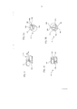
A figura 3A é uma vista em perspectiva do dispositivo de controle de sangue da fi- gura 1 após a agulha ser retirada;Figure 3A is a perspective view of the blood control device of figure 1 after the needle is removed;
A figura 3B é uma vista em seção transversal do dispositivo de controle de sangue da figura 3A ilustrando o posicionamento relativo das placas que formam a porção de válvu- la interna;Figure 3B is a cross-sectional view of the blood control device of figure 3A illustrating the relative positioning of the plates that form the inner valve portion;
A figura 4A é uma vista em perspectiva do dispositivo de controle de sangue da fi- gura 1 com a inserção de um dispositivo Luer de acordo com determinadas modalidades da presente invenção;Figure 4A is a perspective view of the blood control device of figure 1 with the insertion of a Luer device according to certain embodiments of the present invention;
A figura 4B é uma vista em seção transversal do dispositivo de controle de sangue da figura 4A ilustrando o posicionamento relativo das placas que formam a porção de válvu- la interna;Figure 4B is a cross-sectional view of the blood control device in Figure 4A illustrating the relative positioning of the plates that form the inner valve portion;
A figura 5 é uma vista em seção transversal de uma modalidade de um dispositivo de controle de sangue de acordo com a presente invenção após a remoção de um dispositi- vo Luer a partir do conjunto de cateter intravenoso;Figure 5 is a cross-sectional view of an embodiment of a blood control device according to the present invention after removing a Luer device from the intravenous catheter assembly;
A figura 6 é uma vista em perspectiva de uma modalidade de um dispositivo de controle de sangue dotado da agulha inserida no mesmo de acordo com a presente inven- ção;Figure 6 is a perspective view of an embodiment of a blood control device provided with the needle inserted therein according to the present invention;
A figura 7A é uma vista em perspectiva de uma modalidade de um dispositivo de controle de sangue em seguida da remoção da agulha de acordo com determinadas modali- dades da presente invenção;Figure 7A is a perspective view of an embodiment of a blood control device following removal of the needle according to certain modalities of the present invention;
A figura 7B é uma vista em perspectiva alternativa do dispositivo de controle de sangue da figura 7A;Figure 7B is an alternative perspective view of the blood control device of Figure 7A;
A figura 8 é uma vista em seção transversal do dispositivo de controle de sangue da figura 7A mostrando o posicionamento relativo das placas que formam a porção de válvula interna;Figure 8 is a cross-sectional view of the blood control device of Figure 7A showing the relative positioning of the plates that form the internal valve portion;
A figura 9A é uma vista em perspectiva de uma modalidade de um dispositivo de controle de sangue acionado para proporcionar um trajeto de fluxo de fluido de acordo com a presente invenção;Figure 9A is a perspective view of an embodiment of a blood control device operated to provide a fluid flow path in accordance with the present invention;
A figura 9B é uma vista em perspectiva alternativa do dispositivo de controle de sangue da figura 9 A; eFigure 9B is an alternative perspective view of the blood control device of Figure 9A; and
A figura 10 é uma vista em seção transversal do dispositivo de controle de sangue da figura 9A mostrando o posicionamento relativo das placas que formam a porção de válvu- la interna e o trajeto de fluido deste modo criado.Figure 10 is a cross-sectional view of the blood control device of Figure 9A showing the relative positioning of the plates that form the inner valve portion and the fluid path thus created.
As modalidades ilustradas da presente invenção serão melhor entendidas com refe- rência aos desenhos, em que partes similares são designadas por números similares atra- vés da especificação. Será prontamente entendido que os componentes da presente inven- ção, como em geral descritos e ilustrados nas figuras aqui, podem ser arranjados e projeta- dos em uma grande variedade de diferentes configurações. Assim, a descrição mais deta- lhada a seguir, como apresentada nas figuras, não pretende limitar o âmbito da presente invenção como reivindicada, mas é meramente representativa das modalidades seleciona- das da presente invenção. A descrição a seguir pretende ser apenas exemplificativa, e sim- plesmente ilustra determinadas modalidades selecionadas de dispositivos, sistemas, e pro- cessos que são consistentes com a presente invenção como aqui reivindicada.The illustrated modalities of the present invention will be better understood with reference to the drawings, in which similar parts are designated by similar numbers throughout the specification. It will be readily understood that the components of the present invention, as generally described and illustrated in the figures here, can be arranged and designed in a wide variety of different configurations. Thus, the following more detailed description, as presented in the figures, is not intended to limit the scope of the present invention as claimed, but is merely representative of the selected embodiments of the present invention. The following description is intended to be illustrative only, and simply illustrates certain selected modalities of devices, systems, and processes that are consistent with the present invention as claimed herein.
Como usado na presente especificação, o termo "agulha" se refere a qualquer dos diversos dispositivos que pode ser usado para perfurar a pele para adquirir acesso intrave- noso, tal como uma agulha hipodérmica, uma agulha de orifício oco, uma faca cirúrgica, e semelhante. O termo "adaptador de cateter" se refere a um dispositivo médico proporcio- nando comunicação de fluido e conexão mecânica entre um cateter intravenoso e outro dis- positivo de acesso vascular, tal como um dispositivo de segurança de agulha, seringa, tubo intravenoso, ou semelhante. O termo "dispositivo Luer" se refere a um dispositivo médico que inclui dimensões padrão afuniladas Luer, conforme determinado nos padrões da Orga- nização Internacional de Padronização “International Organization for Standardization” ("ISO") 594. As referidas dimensões de afunilamento padronizadas permitem que um ou mais dos dispositivos Luer sejam interconectados por características de interconexão macho e fêmea.As used in the present specification, the term "needle" refers to any of several devices that can be used to pierce the skin to gain intravenous access, such as a hypodermic needle, a hollow orifice needle, a surgical knife, and similar. The term "catheter adapter" refers to a medical device providing fluid communication and mechanical connection between an intravenous catheter and another vascular access device, such as a needle, syringe, intravenous tube, or similar. The term "Luer device" refers to a medical device that includes standard Luer tapered dimensions, as determined by the standards of the International Organization for Standardization ("ISO") 594. These standardized tapered dimensions allow that one or more of the Luer devices are interconnected by male and female interconnect characteristics.
Com referência agora à figura 1, um conjunto de cateter intravenoso 100 de acordo com a presente invenção pode incluir um adaptador de cateter 102, um cateter 110, uma agulha 112, e uma válvula de controle de sangue 114. Cada componente 102, 110, 112, 114 do conjunto de cateter intravenoso 100 pode se alinhar com o outro ao longo de um eixo longitudinal 122, e pode ser adaptado para montagem como discutido em maiores detalhes abaixo.Referring now to Figure 1, an
O adaptador de cateter 102 pode ser longitudinalmente orientado em torno do eixo longitudinal 122 e pode incluir uma extremidade proximal 104, uma extremidade distai 106, e uma região interior oca 108 que se estende entre as mesmas. As extremidades proximal e distai 104, 106 podem ser configuradas para receber a agulha 112 através das mesmas ao longo do eixo longitudinal 122. Especificamente, a ponta da agulha (não mostrada) pode ser introduzida através da extremidade proximal 104 do adaptador de cateter 102 e se estende através da região interior oca 108 para sair na extremidade distai 106 da mesma. Em algu- mas modalidades, as extremidades proximal e distai 104, 106 podem incluir superfícies in- ternas substancialmente lisas para facilitar a manipulação da agulha 112 através das mes- mas.The
Em uma modalidade, uma superfície externa do adaptador de cateter 102 pode ser substancialmente cilíndrica e moldada ao longo do eixo longitudinal 122 para proporcionar um empunhamento seguro e confortável. Em algumas modalidades, por exemplo, o adapta- dor de cateter 102 pode incluir ranhuras, nervuras ou outra superfície externa texturizada para facilitar um empunhamento seguro.In one embodiment, an outer surface of
O adaptador de cateter 102 pode adicionalmente incluir um cateter 110 que se es- tende a partir de sua extremidade distai 106. O cateter 110 pode ser integral ao adaptador de cateter 102 ou acoplado ao mesmo. O adaptador de cateter 102 e o cateter 110 podem cooperar para guiar a agulha 112 de modo que a ponta da agulha (não mostrada) pode se salientar através do cateter 110 para facilitar um processo de cateterização intravenoso. Da mesma forma, a agulha 112 pode ser seletivamente retraída a partir do cateter 110 e adap- tador de cateter 102 após uso.
A válvula de controle de sangue 114 pode ser posicionada dentro da região interior oca 108 do adaptador de cateter 102 para mediar o fluxo de fluido entre o cateter 110 e a extremidade distai 106 do adaptador de cateter 102. A válvula de controle de sangue 114 pode incluir um invólucro externo helicoidal substancialmente flexível 116 e uma porção de válvula interna 118 formada no mesmo. O invólucro externo 116 pode incluir um material elastomérico tal como borracha de silicone, ou qualquer outro material adequado conhecido daqueles versados na técnica. Da mesma forma, a porção de válvula interna 118 pode tam- bém ser formada de um material elastomérico ou outro material adequado.The
O invólucro externo 116 pode ser orientado dentro do adaptador de cateter 102 de modo que uma superfície externa do invólucro externo 116 se encontre substancialmente adjacente a uma superfície interna do adaptador de cateter 102, com a borda distai 124 da válvula de controle de sangue 114 exposta dentro da região interior oca 108.The
A porção de válvula interna 118 formada dentro do invólucro externo 116 pode in- cluir porções correspondentes 120a, 120b. Em algumas modalidades, as porções corres- pondentes 120a, 120b podem ser substancialmente flexíveis e adaptadas para receber a agulha 112 entre as mesmas, deste modo facilitando um procedimento de cateterização intravenoso. Especificamente, a ponta da agulha (não mostrada) pode ser avançada através de uma junção correspondente 126 formada entre as porções correspondentes 120a, 120b, deste modo deformando as porções correspondentes 120a, 120b conforme necessário para acomodar o diâmetro da agulha 112.The
As porções correspondentes 120a, 120b podem de outro modo substancialmente se alinhar onde o invólucro externo 116 está em um estado não comprimido. A junção cor- respondente 126 formada deste modo pode proporcionar controle de vazamento de fluido para permitir continuada visibilidade de refluxo de sangue através de um procedimento de inserção de cateter. A referida característica da presente invenção pode facilitar o posicio- namento adequado do cateter 110 dentro de um vaso sanguíneo.Corresponding
Com referência agora à figura 2, a agulha 112 pode ser gradualmente retraída atra- vés do cateter 110 e adaptador de cateter 102 uma vez que o cateter 110 é adequadamente posicionado dentro de um vaso sanguíneo. Em algumas modalidades, a agulha 112 e a vál- vula de controle de sangue 114 podem cooperar para permitir continuada visibilidade de refluxo de sangue através do referido procedimento de cateterização intravenoso, deste mo- do proporcionando confirmação continuada de que o cateter 110 é adequadamente posicio- nado dentro do vaso sanguíneo.Referring now to figure 2,
Particularmente, a câmara de refluxo (não mostrada) fixada à extremidade distai (não mostrada) da agulha 112 pode permitir que um trabalhador de cuidado da saúde visua- lize o refluxo de sangue dentro da câmara de refluxo ao perfurar um vaso sanguíneo com a agulha 112. O ângulo no qual a agulha 112 e o cateter 110 são ajustados pode então ser reduzido para facilitar o avanço do cateter 110 dentro do vaso sanguíneo. A agulha 112 po- de ser gradualmente retraída a partir de dentro do cateter 110, deste modo liberando uma vedação entre a agulha 112 e o cateter 110 e criando um espaço anular 204 entre a extre- midade proximal (não mostrada) do cateter 110 e a ponta da agulha 202. Refluxo de sangue pode gradualmente preencher o referido espaço anular 204, proporcionando continuada evidencia de posicionamento adequado do cateter 110 dentro do vaso sanguíneo.In particular, the reflux chamber (not shown) attached to the distal end (not shown) of
Finalmente, o cateter 110 pode ser avançado para dentro do vaso sanguíneo até que a extremidade proximal 104 do adaptador de cateter 102 alcance a pele do paciente. A agulha 112 pode então ser retirada em uma direção 200 de modo que a ponta da agulha 202 sai do cateter 110, da válvula de controle de sangue 114, e finalmente da extremidade distai 106 do adaptador de cateter 102. A flexibilidade das porções correspondentes 120a, 120b formando a porção de válvula interna 118 da válvula de controle de sangue 114 pode fazer com que as porções correspondentes 120a, 120b substancialmente se re-alinhem em seguida da retração da ponta da agulha 202 adiante da junção correspondente 126. Embora o referido realinhamento efetivamente evite um livre fluxo de sangue dentro do adaptador de cateter 102 com a retirada da agulha 112 e sem necessitar de oclusão digital do vaso san- guíneo, a válvula de controle de sangue 114 continua a permitir vazamento de fluido visível, controlado adiante da junção correspondente 126 e para dentro da porção distal do adapta- dor de cateter 102. A referida característica da presente invenção pode permitir a confirma- ção final de que o cateter 110 está adequadamente posicionado dentro do vaso sanguíneo.Finally,
Com referência agora às Figuras 3 A e 3B, um adaptador de cateter 102 alojando a válvula de controle de sangue 114 de acordo com a presente invenção pode ser configurado para acomodar um dispositivo Luer 300 inserido na extremidade distai 106 do mesmo. Um dispositivo Luer 300 pode inclui, por exemplo, uma seringa, um cateter, uma agulha dotada de cubo, um tubo intravenoso, um conjunto de administração de fluido, ou qualquer outro dispositivo conhecido daqueles versados na técnica. O dispositivo Luer 300 pode incluir um afunilamento 302 dotado de um diâmetro externo 306 pelo menos relativamente menor do que um diâmetro interno 310 da extremidade distai 106 do adaptador de cateter 102. As dimensões do afunilamento 302 e os diâmetros 306, 310 do afunilamento 302 e extremidade distai 106 do adaptador de cateter 102, entretanto, podem variar dentro de tolerâncias pa- drão conhecidas daqueles versados na técnica.With reference now to Figures 3A and 3B, a
A válvula de controle de sangue 114 pode ser posicionada dentro da região interior oca 108 do adaptador de cateter 102 de modo que a válvula de controle de sangue 114 po- de ser efetivamente comprimida ao inserir o dispositivo Luer 300 na extremidade distai 106 do adaptador de cateter 102. Especificamente, em algumas modalidades, o formato helicoi- dal do invólucro externo 116 da válvula de controle de sangue 114 pode resultar nas bordas distal e proximal 124, 312 sendo anguladas uma com relação a outra, e sendo adicional- mente angulada com relação a a extremidade distai 106 do adaptador de cateter 102. Na referida posição, a porção de válvula interna 118 da válvula de controle de sangue 114 pode ser substancialmente fechada de modo que, em determinadas modalidades, as porções correspondentes 120a, 120b são substancialmente alinhadas.The
A extremidade proximal 304 do dispositivo Luer 300 pode ser substancialmente pa- ralela à extremidade distai 106 do adaptador de cateter 102. Deste modo, a inserção da ex- tremidade proximal 304 do dispositivo Luer 300 na extremidade distai 106 do adaptador de cateter 102 pode resultar no invólucro externo 116 sendo progressivamente comprimido a partir de sua ponta mais distai 314, como discutido em mais detalhes abaixo.The
Com referência agora à Figuras 4A e 4B, inserir o dispositivo Luer 300 na extremi- dade distai 106 do adaptador de cateter 102 pode comprimir a válvula de controle de sangue 114 que se encontra no mesmo. Especificamente, a extremidade proximal 304 do dispositivo Luer 300 pode inicialmente entrar em contato com a ponta mais distai 314 do invólucro ex- terno 116 e progressivamente lançar a borda distai 124 em direção da extremidade proximal 104 do adaptador de cateter 102.Referring now to Figures 4A and 4B, inserting the
Em determinadas modalidades, o adaptador de cateter 102 pode incluir uma porção de ombro 400 para definir a posição dentro da região interior oca 108 que é substancialmen- te perpendicular ao eixo longitudinal 122, e limitar a translação da válvula de controle de sangue 114 além daquela posição. Nas referidas modalidades, inserir o dispositivo Luer 300 dentro do adaptador de cateter 102 pode lançar a borda distai 124 do invólucro externo 116 em uma direção 402 em direção da porção de ombro 400. Dependendo da posição inicial da válvula de controle de sangue 114 dentro da região interior oca 108, inserir o dispositivo Lu- er 300 adicionalmente dentro do adaptador de cateter 102 pode transladar a válvula de con- trole de sangue 114 dentro da região interior oca 116 na mesma direção 402. A porção de ombro 400, entretanto, pode limitar a translação da válvula de controle de sangue 114 na direção 402 além da posição onde a borda proximal 312 do invólucro externo 116 substan- cialmente entra em contato com a porção de ombro 400.In certain embodiments, the
A compressão da válvula de controle de sangue 114 deste modo pode inclinar o in- vólucro externo helicoidal 116, deste modo abrindo a porção de válvula interna 118 para criar um trajeto de fluido 404. Particularmente, como discutido em mais detalhes abaixo, porções correspondentes 120a, 120b formando a porção de válvula interna 118 podem se desalinhar para permitir fluxo controlado de fluido a partir do dispositivo Luer 300 através da válvula de controle de sangue 114, em uma direção 402 em direção da extremidade proxi- mal 104 do adaptador de cateter 102 e cateter fixado 110.Compression of the
Retirada o dispositivo Luer 300 a partir do adaptador de cateter 102 pode liberar a válvula de controle de sangue 114 a partir desta posição comprimida, permitindo que as porções correspondentes 120a, 120b se realinhem para substancialmente fechar a porção de válvula interna 118. Alternativamente, como mostrado na figura 5, o invólucro externo helicoidal 116 pode permanecer inclinado em seguida da retirada do dispositivo Luer 300 a partir do adaptador de cateter 102. Neste caso, as porções correspondentes 120a, 120b podem permanecer em um estado desalinhado, deste modo mantendo um trajeto de fluido 404 entre o dispositivo Luer 300 e a extremidade proximal 104 do adaptador de cateter 102.Removing the
Com referência agora à figura 6, da mesma forma que o invólucro externo 116, a porção de válvula interna 118 da válvula de controle de sangue 114 pode ser formada de um material substancialmente elastomérico tal como borracha de silicone, ou outro material adequado conhecido daqueles versados na técnica. Como resultado, as porções correspon- dentes 120a, 120b que constituem a porção de válvula interna 118 podem se deformar con- forme necessário para acomodar uma agulha de introdução 112 inserida através das mes- mas. A referida característica pode permitir que a fabricação simples e/ou o retroencaixe de um conjunto de cateter intravenoso incorporando a válvula de controle de sangue 114 de acordo com a presente invenção, e ainda otimizar o controle do sangue e visibilidade do refluxo através de um procedimento de cateterização intravenoso.Referring now to Figure 6, in the same way as the
Embora a deformação das porções correspondentes 120a, 120b para acomodar a agulha 112 possa permitir um vazamento relativamente maior de fluido na extremidade dis- tai 106 do adaptador de cateter 102 enquanto a agulha 112 se estende através da junção correspondente 126, a natureza flexível das porções correspondentes 120a, 120b pode con- tinuar a limitar o vazamento de fluido para proporcionar um tempo maior durante o qual se pode realizar um procedimento de cateterização intravenoso e minimizar a quantidade de manipulação física necessária para tal. Deste modo, as modalidades da presente invenção podem significantemente reduzir a possibilidade de refluxo de sangue transbordando o adaptador de cateter 102 durante um procedimento de cateterização intravenoso e ocasio- nando danos relacionados à exposição de sangue.Although deformation of the corresponding
Com referência agora às Figuras 7 A e 7B, e como mencionado acima, a válvula de controle de sangue 114 de acordo com determinadas modalidades da presente invenção pode ser substancialmente de natureza monolítica, de modo que a porção de válvula interna 118 é uma parte integral do invólucro externo 116. Alternativamente, o invólucro externo 116 e porção de válvula interna 118 podem ser moldados independentemente um do outro e acoplados juntos de modo que a porção de válvula interna 118 se estende circunferencial- mente para dentro a partir do invólucro externo 116 para substancialmente ocupar um espa- ço anular formado pelo invólucro externo helicoidal 116 em seu estado não comprimido.With reference now to Figures 7A and 7B, and as mentioned above, the
Em qualquer caso, o invólucro externo substancialmente helicoidal 116 pode incluir bordas laterais 700a, 700b que são inclinadas uma com relação a outra. Como anteriormen- te discutido, a porção de válvula interna 118 pode incluir porções correspondentes 120a, 120b as quais se estendem para dentro a partir do invólucro externo 116 para formar uma junção correspondente substancialmente linear 126 quando o invólucro externo 116 está em seu estado não comprimido.In any case, the substantially helical
Com referência agora à figura 8, a junção correspondente 126 formada pelas por- ções correspondentes 120a, 120b da porção de válvula interna 118 onde o invólucro externo 116 está em seu estado não comprimido pode substancialmente bloquear o fluxo de fluido através do mesmo. Pelo fato da junção correspondente 126 não ser uma junta de vedação, entretanto, fluido pode mesmo assim escorrer lentamente através da junção correspondente 126 para permitir continuada visibilidade do refluxo após a agulha 112 ser removida. Este contínuo controle de vazamento de fluido através da válvula de controle de sangue 114 da presente invenção facilita a precisão e a eficiência em realizar procedimentos de cateteriza- ção intravenosos.Referring now to Figure 8, the corresponding
Com referência agora às Figuras 9A, 9B, e 10, comprimir o invólucro externo heli- coidal substancialmente flexível 116 pode abrir a porção de válvula interna 118 na junção correspondente 126, deste modo criando um trajeto de fluido 404 entre as porções corres- pondentes 120a, 120b. Especificamente, dependendo da força compressiva aplicada, as bordas laterais 700a, 700b do invólucro externo 116 podem ser trazidas em alinhamento substancial uma com a outra. A referida distorção do formato anteriormente helicoidal do invólucro externo 116 pode por sua vez desalinhar as porções correspondentes 120a, 120b para criar um trajeto de fluido 404.Referring now to Figures 9A, 9B, and 10, compressing the substantially flexible helical
Um coeficiente de fluxo através do trajeto de fluido 404 pode ser variado ao se vari- ar a força compressiva aplicada ao invólucro externo 116, deste modo permitindo o fluxo controlado de fluido através da válvula de controle de sangue 114. Especificamente, um aumento na força compressiva aplicada pode resultar em menos fluxo de fluido restrito e um coeficiente mais rápido de fluxo através da válvula de controle de sangue 114. Em algumas modalidades, a variação controlada na força compressiva aplicada pode ser alcançada ao se selecionar um dispositivo Luer 300 dotado de dimensões de inclinação específicas 302, variando a força com a qual o dispositivo Luer 300 é inserido no adaptador de cateter 102, variando o posicionamento da válvula de controle de sangue 114 dentro da região interior oca 108 do adaptador de cateter 102, e/ou por qualquer outro meio conhecido daqueles ver- sados na técnica.A flow coefficient through
A presente invenção pode ser incorporada em outras formas específicas sem se desviar a partir de suas estruturas, métodos, ou outras características essenciais como amplamente descrito aqui e reivindicado posteriormente aqui. As modalidades descritas devem ser consideradas em todos os seus aspectos apenas como ilustrativas, e não restritivas. O 5 âmbito da presente invenção é, portanto, indicado pelas reivindicações anexas, em vez de pela descrição anterior. Todas as mudanças que se insiram faixa de equivalência das reivindicações devem ser englobadas pelo âmbito das mesmas.The present invention can be incorporated in other specific forms without deviating from its structures, methods, or other essential features as widely described here and claimed later here. The described modalities should be considered in all its aspects only as illustrative, and not restrictive. The scope of the present invention is therefore indicated by the appended claims, rather than by the previous description. All changes that fall within the equivalence range of the claims must be encompassed by their scope.
Claims (19)
Applications Claiming Priority (3)
| Application Number | Priority Date | Filing Date | Title |
|---|---|---|---|
| US12/119.351 | 2008-05-12 | ||
| US12/119,351 US8366684B2 (en) | 2008-05-12 | 2008-05-12 | Intravenous catheter blood control device |
| PCT/US2009/036838 WO2009139952A1 (en) | 2008-05-12 | 2009-03-11 | Intravenous catheter blood control device |
Publications (3)
| Publication Number | Publication Date |
|---|---|
| BRPI0911965A2 BRPI0911965A2 (en) | 2016-04-26 |
| BRPI0911965B1 true BRPI0911965B1 (en) | 2020-09-29 |
| BRPI0911965B8 BRPI0911965B8 (en) | 2021-06-22 |
Family
ID=40548740
Family Applications (1)
| Application Number | Title | Priority Date | Filing Date |
|---|---|---|---|
| BRPI0911965A BRPI0911965B8 (en) | 2008-05-12 | 2009-03-11 | apparatus and method for controlling blood flow through an intravenous catheter |
Country Status (10)
| Country | Link |
|---|---|
| US (1) | US8366684B2 (en) |
| EP (2) | EP3159031B1 (en) |
| JP (1) | JP5485985B2 (en) |
| AU (1) | AU2009246803B2 (en) |
| BR (1) | BRPI0911965B8 (en) |
| CA (1) | CA2723807C (en) |
| ES (2) | ES2609768T3 (en) |
| MX (1) | MX2010012283A (en) |
| NZ (1) | NZ589233A (en) |
| WO (1) | WO2009139952A1 (en) |
Families Citing this family (18)
| Publication number | Priority date | Publication date | Assignee | Title |
|---|---|---|---|---|
| US8746248B2 (en) | 2008-03-31 | 2014-06-10 | Covidien Lp | Determination of patient circuit disconnect in leak-compensated ventilatory support |
| US8267085B2 (en) | 2009-03-20 | 2012-09-18 | Nellcor Puritan Bennett Llc | Leak-compensated proportional assist ventilation |
| US8272380B2 (en) | 2008-03-31 | 2012-09-25 | Nellcor Puritan Bennett, Llc | Leak-compensated pressure triggering in medical ventilators |
| EP2313138B1 (en) | 2008-03-31 | 2018-09-12 | Covidien LP | System and method for determining ventilator leakage during stable periods within a breath |
| EP2381999B1 (en) * | 2008-12-30 | 2018-02-21 | Cook Medical Technologies LLC | Splittable introducer, hemostatic valve and method for producing the same |
| US8424521B2 (en) | 2009-02-27 | 2013-04-23 | Covidien Lp | Leak-compensated respiratory mechanics estimation in medical ventilators |
| US8418691B2 (en) | 2009-03-20 | 2013-04-16 | Covidien Lp | Leak-compensated pressure regulated volume control ventilation |
| US9498589B2 (en) | 2011-12-31 | 2016-11-22 | Covidien Lp | Methods and systems for adaptive base flow and leak compensation |
| US9675771B2 (en) | 2013-10-18 | 2017-06-13 | Covidien Lp | Methods and systems for leak estimation |
| SG10202007098SA (en) | 2014-04-18 | 2020-08-28 | Becton Dickinson Co | Needle capture safety interlock for catheter |
| WO2016007650A1 (en) * | 2014-07-08 | 2016-01-14 | Applied Medical Resources Corporation | Highly responsive instrument seal |
| DK3552652T3 (en) | 2015-08-18 | 2021-07-12 | Braun Melsungen Ag | CATHETER FACILITIES WITH VALVES |
| JP7007284B2 (en) | 2016-02-18 | 2022-01-24 | スミスズ メディカル エーエスディー,インコーポレイティド | Closed catheter |
| US11344220B2 (en) | 2016-05-13 | 2022-05-31 | Becton, Dickinson And Company | Invasive medical device cover with magnet |
| US10032552B2 (en) * | 2016-08-30 | 2018-07-24 | Becton, Dickinson And Company | Cover for tissue penetrating device with integrated magnets and magnetic shielding |
| USD808013S1 (en) | 2016-10-27 | 2018-01-16 | Smiths Medical Asd, Inc. | Catheter |
| JP6861290B2 (en) * | 2016-11-09 | 2021-04-21 | ボストン サイエンティフィック リミテッド | Hemostasis valve and hemostatic valve assembly |
| WO2020127328A1 (en) | 2018-12-17 | 2020-06-25 | B. Braun Melsungen Ag | Over-the-needle catheter assemblies and related manufacturing method |
Family Cites Families (78)
| Publication number | Priority date | Publication date | Assignee | Title |
|---|---|---|---|---|
| US3811440A (en) * | 1971-08-09 | 1974-05-21 | Deseret Pharma | Catheter placement unit with pressure closure |
| US3856010A (en) * | 1971-08-09 | 1974-12-24 | Deseret Pharma | Catheter placement unit with pressure closure |
| FR2220729B1 (en) * | 1973-03-06 | 1975-10-31 | Technological Supply | |
| US3977400A (en) * | 1974-11-29 | 1976-08-31 | Deseret Pharmaceutical Co., Inc. | Catheter placement unit with resilient sleeve and manual sleeve closure |
| DE2817102C2 (en) * | 1978-04-19 | 1985-01-24 | Dr. Eduard Fresenius, Chemisch-pharmazeutische Industrie KG, 6380 Bad Homburg | Connector for plastic cannulas or venous catheters |
| US4449693A (en) * | 1982-09-30 | 1984-05-22 | Gereg Gordon A | Catheter check valve |
| JPS5962062A (en) * | 1982-10-01 | 1984-04-09 | メデイキツト株式会社 | Cap of cathetel |
| US4634432A (en) * | 1985-05-13 | 1987-01-06 | Nuri Kocak | Introducer sheath assembly |
| GB8527646D0 (en) * | 1985-11-08 | 1985-12-11 | Cox J A | Devices for sampling drainage |
| GB8627808D0 (en) * | 1986-11-20 | 1986-12-17 | Cox J A | Sampling liquids from human/animal body |
| US4842591A (en) * | 1988-01-21 | 1989-06-27 | Luther Ronald B | Connector with one-way septum valve, and assembly |
| DE3809127C1 (en) * | 1988-03-18 | 1989-04-13 | B. Braun Melsungen Ag, 3508 Melsungen, De | |
| US4874377A (en) * | 1988-05-26 | 1989-10-17 | Davis Newgard Revocable Family Living Trust | Self-occluding intravascular cannula assembly |
| US5064416A (en) * | 1988-05-26 | 1991-11-12 | Newgard Kent W | Self-occluding intravascular cannula assembly |
| JP2505871B2 (en) * | 1988-11-14 | 1996-06-12 | 株式会社ニッショー | Communication tool when used |
| DE4000764A1 (en) * | 1990-01-12 | 1991-07-18 | Braun Melsungen Ag | APPROACH |
| US5053014A (en) * | 1990-02-01 | 1991-10-01 | Critikon, Inc. | Catheter with controlled valve |
| US5041097A (en) * | 1990-02-26 | 1991-08-20 | Johnson Gerald W | Intravenous catheter fitting with protective end seal |
| US5062836A (en) * | 1990-03-14 | 1991-11-05 | The Kendall Company | Placement device for a catheter and guide wire |
| US5084023A (en) * | 1990-03-22 | 1992-01-28 | Critikon, Inc. | Bloodless catheter with self-shielding needle |
| US5127905A (en) * | 1990-05-02 | 1992-07-07 | Critikon, Inc. | Stickless catheter with manual shut-off valve |
| US5108374A (en) * | 1990-05-02 | 1992-04-28 | Critikon, Inc. | Stickless catheter with manual shut-off valve |
| US5098394A (en) * | 1990-05-31 | 1992-03-24 | Luther Ronald B | Biased shut off valve assembly for needle and catheter |
| US5085645A (en) * | 1990-08-15 | 1992-02-04 | Becton, Dickinson And Company | Apparatus and method for a catheter adapter with valve |
| US5154703A (en) * | 1990-10-30 | 1992-10-13 | Care Medical Devices, Inc. | Bloodless catheter |
| US5156596A (en) * | 1991-02-04 | 1992-10-20 | Menlo Care, Inc. | Catheter with changeable number of lumens |
| US5295969A (en) * | 1992-04-27 | 1994-03-22 | Cathco, Inc. | Vascular access device with air-tight blood containment capability |
| US5234410A (en) * | 1992-10-23 | 1993-08-10 | Vlv Associates | Catheter assembly |
| US5330435A (en) * | 1993-04-08 | 1994-07-19 | Vaillancourt Vincent L | Valve for a catheter assembly |
| DE4311715C2 (en) * | 1993-04-08 | 1996-02-01 | Fresenius Ag | Port cannula |
| US5380305A (en) * | 1993-04-20 | 1995-01-10 | Jerry D. Rockhold, Jr. | Hemostatic safety catheter-cannula assembly |
| US5350363A (en) * | 1993-06-14 | 1994-09-27 | Cordis Corporation | Enhanced sheath valve |
| US5657963A (en) * | 1993-06-16 | 1997-08-19 | United States Surgical Corporation | Seal assembly for accommodating introduction of surgical instruments |
| ES2074012B1 (en) * | 1993-08-17 | 1996-03-16 | Teixidor Pere Arques | INTRAVASCULAR PUNCTURE CANNULA WITH AUTOMATIC ANTI-REFLUX BLOOD MECHANISM |
| US5352205A (en) * | 1993-09-16 | 1994-10-04 | Lawrence Dales | Bloodless insertion catheter assembly |
| JP2584597B2 (en) | 1993-09-29 | 1997-02-26 | ベクトン・ディッキンソン・アンド・カンパニー | Catheter introduction device with blood seal |
| US5806831A (en) * | 1993-10-13 | 1998-09-15 | Paradis; Joseph R. | Control of fluid flow with internal cannula |
| US5549577A (en) * | 1993-12-29 | 1996-08-27 | Ivac Corporation | Needleless connector |
| US5522804A (en) * | 1994-02-15 | 1996-06-04 | Lynn; Lawrence A. | Aspiration, mixing, and injection syringe |
| US5405323A (en) * | 1994-02-22 | 1995-04-11 | Aeroquip Corporation | Catheter check valve assembly |
| US5487728A (en) * | 1994-05-19 | 1996-01-30 | Vaillancourt; Vincent L. | Connector assembly |
| US5429616A (en) * | 1994-05-31 | 1995-07-04 | Schaffer; David I. | Occludable catheter |
| US5549566A (en) * | 1994-10-27 | 1996-08-27 | Abbott Laboratories | Valved intravenous fluid line infusion device |
| DE4442352C1 (en) * | 1994-11-29 | 1995-12-21 | Braun Melsungen Ag | Valve arrangement provided in connector for use e.g. with cannula |
| US5520666A (en) * | 1994-12-06 | 1996-05-28 | Abbott Laboratories | Valved intravenous fluid line connector |
| US5575769A (en) * | 1995-05-30 | 1996-11-19 | Vaillancourt; Vincent L. | Cannula for a slit septum and a lock arrangement therefore |
| US5782816A (en) * | 1995-09-07 | 1998-07-21 | David R. Kipp | Bi-directional valve and method of using same |
| IT1285266B1 (en) * | 1996-02-26 | 1998-06-03 | Borla Ind | CONNECTOR WITH PROTECTION VALVE FOR INFUSION / TRANSFUSION AND SIMILAR MEDICAL LINES. |
| US5817069A (en) * | 1996-02-28 | 1998-10-06 | Vadus, Inc. | Valve assembly |
| US5651772A (en) * | 1996-02-28 | 1997-07-29 | Aeroquip Corporation | Needle guard assembly |
| US5749857A (en) * | 1996-04-25 | 1998-05-12 | Cuppy; Michael J. | Catheter system |
| US6273869B1 (en) * | 1996-06-13 | 2001-08-14 | Vincent L. Vaillancourt | Valve connector |
| US5738144A (en) * | 1996-10-11 | 1998-04-14 | Aeroquip Corporation | Luer connecting coupling |
| US6883778B1 (en) * | 1996-11-18 | 2005-04-26 | Nypro Inc. | Apparatus for reducing fluid drawback through a medical valve |
| EP0952868B1 (en) * | 1996-11-18 | 2004-03-31 | Nypro, Inc. | Swabbable luer-coned valve |
| US5967490A (en) * | 1997-01-08 | 1999-10-19 | Vadus, Inc. | Catheter hubs having a valve |
| US5954698A (en) * | 1997-01-08 | 1999-09-21 | Vadus, Inc. | Catheter apparatus having valved catheter hub and needle protector |
| US5911710A (en) * | 1997-05-02 | 1999-06-15 | Schneider/Namic | Medical insertion device with hemostatic valve |
| US6117108A (en) * | 1997-08-20 | 2000-09-12 | Braun Melsungen Ag | Spring clip safety IV catheter |
| US6077244A (en) * | 1998-04-30 | 2000-06-20 | Mdc Investment Holdings, Inc. | Catheter insertion device with retractable needle |
| NL1007997C2 (en) | 1998-01-09 | 1999-07-12 | Cordis Europ | Device for inserting an elongated medical device. |
| MXPA00011767A (en) * | 1998-05-29 | 2002-10-17 | Lawrence A Lynn | Luer receiver and method for fluid transfer. |
| US6331176B1 (en) * | 1999-03-11 | 2001-12-18 | Advanced Cardiovascular Systems, Inc. | Bleed back control assembly and method |
| CA2380907C (en) * | 1999-08-12 | 2009-12-08 | Lawrence A. Lynn | Luer receiving vascular access system |
| FR2802432B1 (en) * | 1999-12-16 | 2002-03-08 | Vygon | AUTOMATIC SHUTTER CONNECTOR FOR CONNECTING A LIQUID INJECTION HEAD TO AN INJECTION OUTPUT |
| EP1242141B1 (en) | 1999-12-30 | 2006-05-24 | Cook Vascular Incorporated | Splittable medical valve |
| US6699221B2 (en) * | 2000-06-15 | 2004-03-02 | Vincent L. Vaillancourt | Bloodless catheter |
| JP4996015B2 (en) * | 2001-03-12 | 2012-08-08 | メディキット株式会社 | Indwelling catheter |
| US6506181B2 (en) * | 2001-05-25 | 2003-01-14 | Becton, Dickinson And Company | Catheter having a low drag septum |
| JP3808806B2 (en) * | 2002-06-26 | 2006-08-16 | メディキット株式会社 | Indwelling needle |
| DE20210394U1 (en) * | 2002-07-04 | 2002-09-12 | Braun Melsungen Ag | catheter introducer |
| US7347839B2 (en) * | 2003-02-12 | 2008-03-25 | Nipro Corporation | Indwelling catheter |
| US7470254B2 (en) * | 2003-08-18 | 2008-12-30 | Medical Components, Inc. | Needle with sealing valve |
| US6994315B2 (en) * | 2004-01-13 | 2006-02-07 | Rymed Technologies, Inc. | Swabbable needle-free injection port valve system with neutral fluid displacement |
| US20070083162A1 (en) * | 2005-10-11 | 2007-04-12 | Span-America Medical Systems, Inc. | Valve for intravenous catheter |
| US7670317B2 (en) | 2005-10-25 | 2010-03-02 | Becton, Dickinson And Company | One piece low drag septum |
| US8308691B2 (en) * | 2006-11-03 | 2012-11-13 | B. Braun Melsungen Ag | Catheter assembly and components thereof |
| JP2008043445A (en) * | 2006-08-11 | 2008-02-28 | Medikit Kk | Catheter, hollow needle and dwelling needle assembly |
-
2008
- 2008-05-12 US US12/119,351 patent/US8366684B2/en active Active
-
2009
- 2009-03-11 ES ES09747038.9T patent/ES2609768T3/en active Active
- 2009-03-11 ES ES16198702T patent/ES2697330T3/en active Active
- 2009-03-11 BR BRPI0911965A patent/BRPI0911965B8/en active IP Right Grant
- 2009-03-11 WO PCT/US2009/036838 patent/WO2009139952A1/en active Application Filing
- 2009-03-11 JP JP2011509504A patent/JP5485985B2/en not_active Expired - Fee Related
- 2009-03-11 EP EP16198702.9A patent/EP3159031B1/en active Active
- 2009-03-11 EP EP09747038.9A patent/EP2313141B1/en not_active Not-in-force
- 2009-03-11 MX MX2010012283A patent/MX2010012283A/en active IP Right Grant
- 2009-03-11 NZ NZ589233A patent/NZ589233A/en not_active IP Right Cessation
- 2009-03-11 AU AU2009246803A patent/AU2009246803B2/en not_active Ceased
- 2009-03-11 CA CA2723807A patent/CA2723807C/en not_active Expired - Fee Related
Also Published As
| Publication number | Publication date |
|---|---|
| AU2009246803B2 (en) | 2014-04-24 |
| NZ589233A (en) | 2013-11-29 |
| EP2313141A1 (en) | 2011-04-27 |
| JP5485985B2 (en) | 2014-05-07 |
| EP3159031B1 (en) | 2018-08-22 |
| MX2010012283A (en) | 2011-02-22 |
| ES2697330T3 (en) | 2019-01-23 |
| BRPI0911965B8 (en) | 2021-06-22 |
| JP2011519708A (en) | 2011-07-14 |
| EP3159031A1 (en) | 2017-04-26 |
| US20090281481A1 (en) | 2009-11-12 |
| ES2609768T3 (en) | 2017-04-24 |
| EP2313141B1 (en) | 2016-11-16 |
| CA2723807C (en) | 2017-08-15 |
| US8366684B2 (en) | 2013-02-05 |
| AU2009246803A1 (en) | 2009-11-19 |
| CA2723807A1 (en) | 2009-11-19 |
| WO2009139952A1 (en) | 2009-11-19 |
| BRPI0911965A2 (en) | 2016-04-26 |
Similar Documents
| Publication | Publication Date | Title |
|---|---|---|
| BRPI0911965B1 (en) | APPARATUS AND METHOD TO CONTROL BLOOD FLOW THROUGH AN INTRAVENOUS CATHETER | |
| US7938805B2 (en) | Radially compressible blood control valve | |
| US9764085B2 (en) | Catheter assemblies with valves and related methods | |
| US20230191085A1 (en) | Vascular access catheter | |
| US7101353B2 (en) | Splittable medical valve | |
| US10052474B2 (en) | Intravenous catheter with pressure activated valve | |
| US7901395B2 (en) | Catheter having staggered lumens and method | |
| BR112018015812B1 (en) | APPLIANCE FOR FLUID TRANSFER THROUGH A PERIPHERALLLY PLACED INTRAVENOUS CATHETER | |
| KR20170047299A (en) | Systems and methods for phlebotomy through a peripheral iv catheter | |
| KR20100051800A (en) | Device for introducing a catheter guide wire into a vessel | |
| US20140358087A1 (en) | Devices for creation of multiple vascular access sites |
Legal Events
| Date | Code | Title | Description |
|---|---|---|---|
| B06F | Objections, documents and/or translations needed after an examination request according [chapter 6.6 patent gazette] | ||
| B06T | Formal requirements before examination [chapter 6.20 patent gazette] | ||
| B07A | Application suspended after technical examination (opinion) [chapter 7.1 patent gazette] | ||
| B06A | Patent application procedure suspended [chapter 6.1 patent gazette] | ||
| B09A | Decision: intention to grant [chapter 9.1 patent gazette] | ||
| B16A | Patent or certificate of addition of invention granted [chapter 16.1 patent gazette] |
Free format text: PRAZO DE VALIDADE: 10 (DEZ) ANOS CONTADOS A PARTIR DE 29/09/2020, OBSERVADAS AS CONDICOES LEGAIS. |
|
| B16C | Correction of notification of the grant [chapter 16.3 patent gazette] |
Free format text: PRAZO DE VALIDADE: 20 (VINTE) ANOS CONTADOS A PARTIR DE 11/03/2009, OBSERVADAS AS CONDICOES LEGAIS. PATENTE CONCEDIDA CONFORME ADI 5.529/DF, QUE DETERMINA A ALTERACAO DO PRAZO DE CONCESSAO |