BRPI0911668B1 - CONTAINER AND PACKING USING THE SAME - Google Patents
CONTAINER AND PACKING USING THE SAME Download PDFInfo
- Publication number
- BRPI0911668B1 BRPI0911668B1 BRPI0911668-0A BRPI0911668A BRPI0911668B1 BR PI0911668 B1 BRPI0911668 B1 BR PI0911668B1 BR PI0911668 A BRPI0911668 A BR PI0911668A BR PI0911668 B1 BRPI0911668 B1 BR PI0911668B1
- Authority
- BR
- Brazil
- Prior art keywords
- container
- layer
- funnel
- ribs
- container body
- Prior art date
Links
Images


Classifications
-
- B—PERFORMING OPERATIONS; TRANSPORTING
- B65—CONVEYING; PACKING; STORING; HANDLING THIN OR FILAMENTARY MATERIAL
- B65D—CONTAINERS FOR STORAGE OR TRANSPORT OF ARTICLES OR MATERIALS, e.g. BAGS, BARRELS, BOTTLES, BOXES, CANS, CARTONS, CRATES, DRUMS, JARS, TANKS, HOPPERS, FORWARDING CONTAINERS; ACCESSORIES, CLOSURES, OR FITTINGS THEREFOR; PACKAGING ELEMENTS; PACKAGES
- B65D51/00—Closures not otherwise provided for
- B65D51/18—Arrangements of closures with protective outer cap-like covers or of two or more co-operating closures
-
- B—PERFORMING OPERATIONS; TRANSPORTING
- B65—CONVEYING; PACKING; STORING; HANDLING THIN OR FILAMENTARY MATERIAL
- B65B—MACHINES, APPARATUS OR DEVICES FOR, OR METHODS OF, PACKAGING ARTICLES OR MATERIALS; UNPACKING
- B65B39/00—Nozzles, funnels or guides for introducing articles or materials into containers or wrappers
- B65B39/007—Guides or funnels for introducing articles into containers or wrappers
-
- B—PERFORMING OPERATIONS; TRANSPORTING
- B65—CONVEYING; PACKING; STORING; HANDLING THIN OR FILAMENTARY MATERIAL
- B65D—CONTAINERS FOR STORAGE OR TRANSPORT OF ARTICLES OR MATERIALS, e.g. BAGS, BARRELS, BOTTLES, BOXES, CANS, CARTONS, CRATES, DRUMS, JARS, TANKS, HOPPERS, FORWARDING CONTAINERS; ACCESSORIES, CLOSURES, OR FITTINGS THEREFOR; PACKAGING ELEMENTS; PACKAGES
- B65D15/00—Containers having bodies formed by interconnecting or uniting two or more rigid, or substantially rigid, sections made of different materials
- B65D15/02—Containers having bodies formed by interconnecting or uniting two or more rigid, or substantially rigid, sections made of different materials of curved, or partially curved, cross-section, e.g. cans, drums
-
- B—PERFORMING OPERATIONS; TRANSPORTING
- B65—CONVEYING; PACKING; STORING; HANDLING THIN OR FILAMENTARY MATERIAL
- B65D—CONTAINERS FOR STORAGE OR TRANSPORT OF ARTICLES OR MATERIALS, e.g. BAGS, BARRELS, BOTTLES, BOXES, CANS, CARTONS, CRATES, DRUMS, JARS, TANKS, HOPPERS, FORWARDING CONTAINERS; ACCESSORIES, CLOSURES, OR FITTINGS THEREFOR; PACKAGING ELEMENTS; PACKAGES
- B65D17/00—Rigid or semi-rigid containers specially constructed to be opened by cutting or piercing, or by tearing of frangible members or portions
- B65D17/28—Rigid or semi-rigid containers specially constructed to be opened by cutting or piercing, or by tearing of frangible members or portions at lines or points of weakness
- B65D17/401—Rigid or semi-rigid containers specially constructed to be opened by cutting or piercing, or by tearing of frangible members or portions at lines or points of weakness characterised by having the line of weakness provided in an end wall
-
- B—PERFORMING OPERATIONS; TRANSPORTING
- B65—CONVEYING; PACKING; STORING; HANDLING THIN OR FILAMENTARY MATERIAL
- B65D—CONTAINERS FOR STORAGE OR TRANSPORT OF ARTICLES OR MATERIALS, e.g. BAGS, BARRELS, BOTTLES, BOXES, CANS, CARTONS, CRATES, DRUMS, JARS, TANKS, HOPPERS, FORWARDING CONTAINERS; ACCESSORIES, CLOSURES, OR FITTINGS THEREFOR; PACKAGING ELEMENTS; PACKAGES
- B65D25/00—Details of other kinds or types of rigid or semi-rigid containers
- B65D25/38—Devices for discharging contents
- B65D25/40—Nozzles or spouts
- B65D25/42—Integral or attached nozzles or spouts
-
- B—PERFORMING OPERATIONS; TRANSPORTING
- B65—CONVEYING; PACKING; STORING; HANDLING THIN OR FILAMENTARY MATERIAL
- B65D—CONTAINERS FOR STORAGE OR TRANSPORT OF ARTICLES OR MATERIALS, e.g. BAGS, BARRELS, BOTTLES, BOXES, CANS, CARTONS, CRATES, DRUMS, JARS, TANKS, HOPPERS, FORWARDING CONTAINERS; ACCESSORIES, CLOSURES, OR FITTINGS THEREFOR; PACKAGING ELEMENTS; PACKAGES
- B65D39/00—Closures arranged within necks or pouring openings or in discharge apertures, e.g. stoppers
- B65D39/0052—Closures arranged within necks or pouring openings or in discharge apertures, e.g. stoppers made in more than one piece
- B65D39/007—Plastic cap-shaped hollow plugs
-
- B—PERFORMING OPERATIONS; TRANSPORTING
- B65—CONVEYING; PACKING; STORING; HANDLING THIN OR FILAMENTARY MATERIAL
- B65D—CONTAINERS FOR STORAGE OR TRANSPORT OF ARTICLES OR MATERIALS, e.g. BAGS, BARRELS, BOTTLES, BOXES, CANS, CARTONS, CRATES, DRUMS, JARS, TANKS, HOPPERS, FORWARDING CONTAINERS; ACCESSORIES, CLOSURES, OR FITTINGS THEREFOR; PACKAGING ELEMENTS; PACKAGES
- B65D43/00—Lids or covers for rigid or semi-rigid containers
- B65D43/02—Removable lids or covers
- B65D43/0202—Removable lids or covers without integral tamper element
- B65D43/0204—Removable lids or covers without integral tamper element secured by snapping over beads or projections
- B65D43/0212—Removable lids or covers without integral tamper element secured by snapping over beads or projections only on the outside, or a part turned to the outside, of the mouth
-
- B—PERFORMING OPERATIONS; TRANSPORTING
- B65—CONVEYING; PACKING; STORING; HANDLING THIN OR FILAMENTARY MATERIAL
- B65D—CONTAINERS FOR STORAGE OR TRANSPORT OF ARTICLES OR MATERIALS, e.g. BAGS, BARRELS, BOTTLES, BOXES, CANS, CARTONS, CRATES, DRUMS, JARS, TANKS, HOPPERS, FORWARDING CONTAINERS; ACCESSORIES, CLOSURES, OR FITTINGS THEREFOR; PACKAGING ELEMENTS; PACKAGES
- B65D77/00—Packages formed by enclosing articles or materials in preformed containers, e.g. boxes, cartons, sacks or bags
- B65D77/10—Container closures formed after filling
- B65D77/20—Container closures formed after filling by applying separate lids or covers, i.e. flexible membrane or foil-like covers
- B65D77/2024—Container closures formed after filling by applying separate lids or covers, i.e. flexible membrane or foil-like covers the cover being welded or adhered to the container
- B65D77/2028—Means for opening the cover other than, or in addition to, a pull tab
- B65D77/2032—Means for opening the cover other than, or in addition to, a pull tab by peeling or tearing the cover from the container
- B65D77/2044—Means for opening the cover other than, or in addition to, a pull tab by peeling or tearing the cover from the container whereby a layer of the container or cover fails, e.g. cohesive failure
- B65D77/2048—Means for opening the cover other than, or in addition to, a pull tab by peeling or tearing the cover from the container whereby a layer of the container or cover fails, e.g. cohesive failure whereby part of the container or cover has been weakened, e.g. perforated or precut
- B65D77/2056—Means for opening the cover other than, or in addition to, a pull tab by peeling or tearing the cover from the container whereby a layer of the container or cover fails, e.g. cohesive failure whereby part of the container or cover has been weakened, e.g. perforated or precut the cover being weakened
-
- B—PERFORMING OPERATIONS; TRANSPORTING
- B65—CONVEYING; PACKING; STORING; HANDLING THIN OR FILAMENTARY MATERIAL
- B65D—CONTAINERS FOR STORAGE OR TRANSPORT OF ARTICLES OR MATERIALS, e.g. BAGS, BARRELS, BOTTLES, BOXES, CANS, CARTONS, CRATES, DRUMS, JARS, TANKS, HOPPERS, FORWARDING CONTAINERS; ACCESSORIES, CLOSURES, OR FITTINGS THEREFOR; PACKAGING ELEMENTS; PACKAGES
- B65D77/00—Packages formed by enclosing articles or materials in preformed containers, e.g. boxes, cartons, sacks or bags
- B65D77/22—Details
- B65D77/24—Inserts or accessories added or incorporated during filling of containers
-
- B—PERFORMING OPERATIONS; TRANSPORTING
- B65—CONVEYING; PACKING; STORING; HANDLING THIN OR FILAMENTARY MATERIAL
- B65D—CONTAINERS FOR STORAGE OR TRANSPORT OF ARTICLES OR MATERIALS, e.g. BAGS, BARRELS, BOTTLES, BOXES, CANS, CARTONS, CRATES, DRUMS, JARS, TANKS, HOPPERS, FORWARDING CONTAINERS; ACCESSORIES, CLOSURES, OR FITTINGS THEREFOR; PACKAGING ELEMENTS; PACKAGES
- B65D83/00—Containers or packages with special means for dispensing contents
- B65D83/06—Containers or packages with special means for dispensing contents for dispensing powdered or granular material
-
- B—PERFORMING OPERATIONS; TRANSPORTING
- B65—CONVEYING; PACKING; STORING; HANDLING THIN OR FILAMENTARY MATERIAL
- B65D—CONTAINERS FOR STORAGE OR TRANSPORT OF ARTICLES OR MATERIALS, e.g. BAGS, BARRELS, BOTTLES, BOXES, CANS, CARTONS, CRATES, DRUMS, JARS, TANKS, HOPPERS, FORWARDING CONTAINERS; ACCESSORIES, CLOSURES, OR FITTINGS THEREFOR; PACKAGING ELEMENTS; PACKAGES
- B65D2251/00—Details relating to container closures
- B65D2251/0003—Two or more closures
- B65D2251/0006—Upper closure
- B65D2251/0018—Upper closure of the 43-type
-
- B—PERFORMING OPERATIONS; TRANSPORTING
- B65—CONVEYING; PACKING; STORING; HANDLING THIN OR FILAMENTARY MATERIAL
- B65D—CONTAINERS FOR STORAGE OR TRANSPORT OF ARTICLES OR MATERIALS, e.g. BAGS, BARRELS, BOTTLES, BOXES, CANS, CARTONS, CRATES, DRUMS, JARS, TANKS, HOPPERS, FORWARDING CONTAINERS; ACCESSORIES, CLOSURES, OR FITTINGS THEREFOR; PACKAGING ELEMENTS; PACKAGES
- B65D2251/00—Details relating to container closures
- B65D2251/0003—Two or more closures
- B65D2251/0068—Lower closure
- B65D2251/0093—Membrane
-
- B—PERFORMING OPERATIONS; TRANSPORTING
- B65—CONVEYING; PACKING; STORING; HANDLING THIN OR FILAMENTARY MATERIAL
- B65D—CONTAINERS FOR STORAGE OR TRANSPORT OF ARTICLES OR MATERIALS, e.g. BAGS, BARRELS, BOTTLES, BOXES, CANS, CARTONS, CRATES, DRUMS, JARS, TANKS, HOPPERS, FORWARDING CONTAINERS; ACCESSORIES, CLOSURES, OR FITTINGS THEREFOR; PACKAGING ELEMENTS; PACKAGES
- B65D2543/00—Lids or covers essentially for box-like containers
- B65D2543/00009—Details of lids or covers for rigid or semi-rigid containers
- B65D2543/00018—Overall construction of the lid
- B65D2543/00064—Shape of the outer periphery
- B65D2543/00074—Shape of the outer periphery curved
- B65D2543/00092—Shape of the outer periphery curved circular
-
- B—PERFORMING OPERATIONS; TRANSPORTING
- B65—CONVEYING; PACKING; STORING; HANDLING THIN OR FILAMENTARY MATERIAL
- B65D—CONTAINERS FOR STORAGE OR TRANSPORT OF ARTICLES OR MATERIALS, e.g. BAGS, BARRELS, BOTTLES, BOXES, CANS, CARTONS, CRATES, DRUMS, JARS, TANKS, HOPPERS, FORWARDING CONTAINERS; ACCESSORIES, CLOSURES, OR FITTINGS THEREFOR; PACKAGING ELEMENTS; PACKAGES
- B65D2543/00—Lids or covers essentially for box-like containers
- B65D2543/00009—Details of lids or covers for rigid or semi-rigid containers
- B65D2543/00018—Overall construction of the lid
- B65D2543/00259—Materials used
- B65D2543/00296—Plastic
-
- B—PERFORMING OPERATIONS; TRANSPORTING
- B65—CONVEYING; PACKING; STORING; HANDLING THIN OR FILAMENTARY MATERIAL
- B65D—CONTAINERS FOR STORAGE OR TRANSPORT OF ARTICLES OR MATERIALS, e.g. BAGS, BARRELS, BOTTLES, BOXES, CANS, CARTONS, CRATES, DRUMS, JARS, TANKS, HOPPERS, FORWARDING CONTAINERS; ACCESSORIES, CLOSURES, OR FITTINGS THEREFOR; PACKAGING ELEMENTS; PACKAGES
- B65D2543/00—Lids or covers essentially for box-like containers
- B65D2543/00009—Details of lids or covers for rigid or semi-rigid containers
- B65D2543/00444—Contact between the container and the lid
- B65D2543/00481—Contact between the container and the lid on the inside or the outside of the container
- B65D2543/00537—Contact between the container and the lid on the inside or the outside of the container on the outside, or a part turned to the outside of the mouth of the container
-
- B—PERFORMING OPERATIONS; TRANSPORTING
- B65—CONVEYING; PACKING; STORING; HANDLING THIN OR FILAMENTARY MATERIAL
- B65D—CONTAINERS FOR STORAGE OR TRANSPORT OF ARTICLES OR MATERIALS, e.g. BAGS, BARRELS, BOTTLES, BOXES, CANS, CARTONS, CRATES, DRUMS, JARS, TANKS, HOPPERS, FORWARDING CONTAINERS; ACCESSORIES, CLOSURES, OR FITTINGS THEREFOR; PACKAGING ELEMENTS; PACKAGES
- B65D2543/00—Lids or covers essentially for box-like containers
- B65D2543/00009—Details of lids or covers for rigid or semi-rigid containers
- B65D2543/00444—Contact between the container and the lid
- B65D2543/00592—Snapping means
- B65D2543/00601—Snapping means on the container
- B65D2543/00611—Profiles
- B65D2543/00638—Rolled edge
-
- B—PERFORMING OPERATIONS; TRANSPORTING
- B65—CONVEYING; PACKING; STORING; HANDLING THIN OR FILAMENTARY MATERIAL
- B65D—CONTAINERS FOR STORAGE OR TRANSPORT OF ARTICLES OR MATERIALS, e.g. BAGS, BARRELS, BOTTLES, BOXES, CANS, CARTONS, CRATES, DRUMS, JARS, TANKS, HOPPERS, FORWARDING CONTAINERS; ACCESSORIES, CLOSURES, OR FITTINGS THEREFOR; PACKAGING ELEMENTS; PACKAGES
- B65D2543/00—Lids or covers essentially for box-like containers
- B65D2543/00009—Details of lids or covers for rigid or semi-rigid containers
- B65D2543/00444—Contact between the container and the lid
- B65D2543/00592—Snapping means
- B65D2543/00601—Snapping means on the container
- B65D2543/00675—Periphery concerned
- B65D2543/00685—Totality
-
- B—PERFORMING OPERATIONS; TRANSPORTING
- B65—CONVEYING; PACKING; STORING; HANDLING THIN OR FILAMENTARY MATERIAL
- B65D—CONTAINERS FOR STORAGE OR TRANSPORT OF ARTICLES OR MATERIALS, e.g. BAGS, BARRELS, BOTTLES, BOXES, CANS, CARTONS, CRATES, DRUMS, JARS, TANKS, HOPPERS, FORWARDING CONTAINERS; ACCESSORIES, CLOSURES, OR FITTINGS THEREFOR; PACKAGING ELEMENTS; PACKAGES
- B65D2543/00—Lids or covers essentially for box-like containers
- B65D2543/00009—Details of lids or covers for rigid or semi-rigid containers
- B65D2543/00444—Contact between the container and the lid
- B65D2543/00592—Snapping means
- B65D2543/00712—Snapping means on the lid
- B65D2543/00722—Profiles
- B65D2543/0074—Massive bead
-
- B—PERFORMING OPERATIONS; TRANSPORTING
- B65—CONVEYING; PACKING; STORING; HANDLING THIN OR FILAMENTARY MATERIAL
- B65D—CONTAINERS FOR STORAGE OR TRANSPORT OF ARTICLES OR MATERIALS, e.g. BAGS, BARRELS, BOTTLES, BOXES, CANS, CARTONS, CRATES, DRUMS, JARS, TANKS, HOPPERS, FORWARDING CONTAINERS; ACCESSORIES, CLOSURES, OR FITTINGS THEREFOR; PACKAGING ELEMENTS; PACKAGES
- B65D2543/00—Lids or covers essentially for box-like containers
- B65D2543/00009—Details of lids or covers for rigid or semi-rigid containers
- B65D2543/00444—Contact between the container and the lid
- B65D2543/00592—Snapping means
- B65D2543/00712—Snapping means on the lid
- B65D2543/00787—Periphery concerned
- B65D2543/00796—Totality
-
- B—PERFORMING OPERATIONS; TRANSPORTING
- B65—CONVEYING; PACKING; STORING; HANDLING THIN OR FILAMENTARY MATERIAL
- B65D—CONTAINERS FOR STORAGE OR TRANSPORT OF ARTICLES OR MATERIALS, e.g. BAGS, BARRELS, BOTTLES, BOXES, CANS, CARTONS, CRATES, DRUMS, JARS, TANKS, HOPPERS, FORWARDING CONTAINERS; ACCESSORIES, CLOSURES, OR FITTINGS THEREFOR; PACKAGING ELEMENTS; PACKAGES
- B65D2577/00—Packages formed by enclosing articles or materials in preformed containers, e.g. boxes, cartons, sacks, bags
- B65D2577/10—Container closures formed after filling
- B65D2577/20—Container closures formed after filling by applying separate lids or covers
- B65D2577/2075—Lines of weakness or apertures
- B65D2577/2091—Lines of weakness or apertures in cover
-
- Y—GENERAL TAGGING OF NEW TECHNOLOGICAL DEVELOPMENTS; GENERAL TAGGING OF CROSS-SECTIONAL TECHNOLOGIES SPANNING OVER SEVERAL SECTIONS OF THE IPC; TECHNICAL SUBJECTS COVERED BY FORMER USPC CROSS-REFERENCE ART COLLECTIONS [XRACs] AND DIGESTS
- Y02—TECHNOLOGIES OR APPLICATIONS FOR MITIGATION OR ADAPTATION AGAINST CLIMATE CHANGE
- Y02W—CLIMATE CHANGE MITIGATION TECHNOLOGIES RELATED TO WASTEWATER TREATMENT OR WASTE MANAGEMENT
- Y02W30/00—Technologies for solid waste management
- Y02W30/50—Reuse, recycling or recovery technologies
- Y02W30/80—Packaging reuse or recycling, e.g. of multilayer packaging
Abstract
recipiente e embalagem utilizando o mesmo é fornecido um recipiente que é utilizado como um recipiente permitindo transferência fácil para outro recipiente sem derramamento de conteúdo no momento de reenchimento. a presente invenção refere-se a um recipiente que é encaixado em um corpo de recipiente de formato tubular tendo uma extremidade aberta, uma parte inferior e uma parede lateral e que transfere conteúdo para um recipiente de conservação. esse recipiente tem: um componente de funil (201) dotado de um funil (220) cujo diâmetro diminui a partir de um lado de abertura maior em direção a um lado de abertura menor e dotado de uma pluralidade de nervuras (228) que estendem radialmente a partir do centro de uma parte de abertura (222) no lado de abertura menor do funil (220) de modo a unir uma parte com outra parte da superfície interna da parte de abertura (222) no lado de abertura menor; e um corpo de recipiente.container and packaging using the same container is provided which is used as a container allowing easy transfer to another container without spilling content at the time of refilling. the present invention relates to a container that is fitted into a tubular-shaped container body having an open end, a bottom and a side wall and which transfers content to a holding container. this container has: a funnel component (201) provided with a funnel (220) whose diameter decreases from a larger opening side towards a smaller opening side and provided with a plurality of radially extending ribs (228) from the center of an opening part (222) on the smaller opening side of the funnel (220) so as to join a part with another part of the inner surface of the opening part (222) on the smaller opening side; and a container body.
Description
A presente invenção refere-se a um recipiente e uma embalagem utilizando o mesmo, e em particular a: um recipiente utilizado para embalar material de forma em pó, granular ou líquida e transferir o conteúdo para outro recipiente; e uma embalagem utilizando o mesmo.The present invention relates to a container and packaging using the same, and in particular to: a container used to package material in powder, granular or liquid form and transfer the contents to another container; and a package using the same.
Alimento em pó como café instantâneo é vendido em geral em um estado sendo contido em um recipiente tendo uma propriedade de vedação elevada como uma garrafa com tampa que mantém uma propriedade de vedação durante conservação. Além disso, para fins de reutilizar o recipiente de conservação após encher novamente o mesmo com conteúdo, uma embalagem de uso de reenchimento também é conhecida que embala o conteúdo de forma simples. Como um recipiente para essa embalagem de uso de reenchimento, por exemplo, um saco, um saco de acessórios e um recipiente de no formato de copo são utilizados.Powdered food such as instant coffee is generally sold in a state being contained in a container having a high sealing property like a bottle with a lid that maintains a sealing property during storage. In addition, for the purpose of reusing the storage container after refilling it with content, a refillable use package is also known that simply packs the contents. As a container for such refill use packaging, for example, a bag, an accessory bag and a cup-shaped container are used.
Além disso, os documentos de patente 1 a 3 descrevem configurações que para reforçar um recipiente de copo fabricado de papel que tem um peso leve e pode ser facilmente descartado, um anel de reforço fabricado de resina é fixado à parte de abertura do recipiente de copo.In addition,
Documento de patente 1: publicação de patente em aberto japonesa número S63- 24464Patent document 1: Japanese open patent publication number S63-24464
Documento de patente 2: publicação de patente em aberto japonesa número H8- 58764Patent document 2: Japanese open patent publication number H8- 58764
Documento de patente 3: publicação de patente em aberto japonesa número 2002- 264918Patent document 3: Japanese open patent publication number 2002- 264918
Documento de patente 4: publicação de patente japonesa número 2895556Patent document 4: Japanese patent publication number 2895556
Documento de patente 5: publicação de patente em aberto japonesa número 2009- 7072Patent document 5: Japanese open patent publication number 2009-7072
O reenchimento de conteúdo de uma embalagem de uso de reenchimento como um saco de acordo com a técnica convencional em um recipiente de conservação é realizado, por exemplo, por encostar a parte de abertura da embalagem de uso de reenchimento aberto contra a parte de abertura do recipiente de conservação e então gradualmente derramando o conteúdo dentro do recipiente de conservação. Não obstante, no momento desse trabalho de reenchimento, o conteúdo pode cair para fora e sujar as mãos e o ambiente em volta em alguns casos. Desse modo, tal sistema não é satisfatoriamente favorável para o usuário.The refilling of the contents of a refill package as a bag according to conventional technique in a conservation container is carried out, for example, by touching the opening part of the open refill package against the opening part of the container. storage container and then gradually pour the contents into the storage container. However, at the time of this refilling work, the contents may fall out and get the hands and the surrounding environment dirty in some cases. Thus, such a system is not satisfactorily favorable for the user.
Desse modo, um objetivo da presente invenção é fornecer: um recipiente que permite reenchimento fácil de conteúdo em outro recipiente e que pode manter a qualidade do conteúdo no momento de armazenagem, transporte, e reenchimento; e uma embalagem utilizando o mesmo.Thus, an objective of the present invention is to provide: a container that allows easy refilling of content in another container and that can maintain the quality of the content during storage, transportation, and refilling; and a package using the same.
A presente invenção refere-se a um recipiente que é adaptado em um corpo de recipiente de formato tubular tendo uma extremidade aberta, uma parte inferior e uma parede lateral e que transfere conteúdo para um recipiente de conservação. Esse recipiente tem: um componente de funil dotado de um funil cujo diâmetro diminui de um lado de abertura maior em direção a um lado de aberta menor e com uma pluralidade de nervuras que estendem radialmente a partir do centro de uma parte de abertura no lado de abertura menor do funil de modo a unir uma parte com outra parte da superfície interna da parte de abertura no lado de abertura menor; e um corpo de recipiente.The present invention relates to a container that is fitted into a tubular-shaped container body having an open end, a bottom and a side wall and which transfers content to a holding container. This container has: a funnel component provided with a funnel whose diameter decreases from a larger opening side towards a smaller opening side and with a plurality of ribs extending radially from the center of an opening portion on the side smaller opening of the funnel in order to join a part with another part of the inner surface of the opening part on the smaller opening side; and a container body.
De acordo com a presente invenção, o reenchimento do conteúdo pode ser executado em um estado em que a parte de abertura de um funil acomodado em um corpo de recipiente é inserido em outro recipiente. Desse modo, um recipiente que permite fácil reenchimento pode ser construído.In accordance with the present invention, refilling of the content can be carried out in a state in which the opening part of a funnel accommodated in a container body is inserted into another container. In this way, a container that allows easy refilling can be built.
A figura 1 é uma vista em perspectiva que mostra uma configuração esquemática de uma embalagem de acordo com a presente invenção.Figure 1 is a perspective view showing a schematic configuration of a package according to the present invention.
A figura 2 é uma vista em perspectiva detalhada de uma embalagem mostrada na figura 1.Figure 2 is a detailed perspective view of a package shown in Figure 1.
A figura 3 é uma vista em seção tomada ao longo da linha lll-lll na figura 1.Figure 3 is a sectional view taken along the line ll-lll in figure 1.
A figura 4 é uma vista plana de uma membrana mostrada na figura 2.Figure 4 is a plan view of a membrane shown in Figure 2.
A figura 5 é uma vista em seção tomada ao longo da linha V-V na figura 4.Figure 5 is a sectional view taken along line V-V in figure 4.
A figura 6 é uma vista em perspectiva mostrando uma situação de uso de uma embalagem de acordo com a presente invenção.Figure 6 is a perspective view showing a situation of using a package according to the present invention.
A figura 7 é uma vista em seção tomada ao longo da linha VII-VII na figura 6.Figure 7 is a sectional view taken along line VII-VII in figure 6.
A figura 8 é uma vista em seção mostrando uma modalidade de uma cobertura tendo uma propriedade de barreira de acordo com a presente invenção, tomada ao longo da linha A-A na figura 9.Figure 8 is a sectional view showing an embodiment of a roof having a barrier property according to the present invention, taken along line A-A in figure 9.
A figura 9 é uma vista inferior de uma cobertura da figura 8.Figure 9 is a bottom view of a cover of Figure 8.
A figura 10 é uma vista em perspectiva geral detalhada incluindo uma vista aumentada que provê uma vista aumentada de uma parte selecionada de um recipiente no qual uma cobertura tendo uma propriedade de barreira da figura 8 é aplicada.Figure 10 is a detailed general perspective view including an enlarged view that provides an enlarged view of a selected part of a container to which a cover having a barrier property of Figure 8 is applied.
A figura 11 é uma vista em seção de uma extremidade de um recipiente em um estado em que um recipiente da figura 10 é fechado.Figure 11 is a sectional view of an end of a container in a state in which a container of Figure 10 is closed.
A figura 12 é um diagrama de explicação de operação de uma cobertura tendo uma propriedade de barreira da figura 8, na forma de uma vista em perspectiva mostrando a relação entre uma cobertura, um recipiente e um jar antes do pote ser cheio novamente de conteúdo.Figure 12 is a diagram explaining the operation of a cover having a barrier property of Figure 8, in the form of a perspective view showing the relationship between a cover, a container and a jar before the pot is filled with content again.
A figura 13 é um diagrama de explicação de operação de uma cobertura mostrada na figura 12, na forma de uma vista em seção de uma parte principal.Figure 13 is a diagram explaining the operation of a roof shown in Figure 12, in the form of a sectional view of a main part.
A figura 14 é um diagrama de explicação de operação de uma cobertura tendo uma propriedade de barreira da figura 8, na forma de uma vista em perspectiva mostrando a relação entre uma cobertura, um recipiente e um pote no curso do pote ser cheio novamente com conteúdo.Figure 14 is a diagram explaining the operation of a cover having a barrier property of Figure 8, in the form of a perspective view showing the relationship between a cover, a container and a pot in the course of the pot being filled again with content .
A figura 15 é um diagrama de explicação de operação de uma cobertura mostrada na figura 14, na foram de uma vista em seção de uma parte principal.Figure 15 is a diagram explaining the operation of a roof shown in figure 14, in the form of a sectional view of a main part.
A figura 16 é uma vista inferior de uma cobertura em um caso em que seis partes fracas de resistência são empregadas, em correspondência com a figura 9.Figure 16 is a bottom view of a cover in a case where six weak parts of resistance are employed, in correspondence with figure 9.
A figura 17 é uma vista em seção mostrando uma configuração de uma cobertura de acordo com uma segunda modalidade, tomada ao longo da linha A-A na figura 18.Figure 17 is a sectional view showing a cover configuration according to a second modality, taken along line A-A in figure 18.
A figura 19 é uma vista em seção mostrando uma configuração de uma terceira modalidade, em correspondência com a figura 17.Figure 19 is a sectional view showing a configuration of a third modality, in correspondence with figure 17.
A figura 20 é uma vista em seção mostrando um exemplo de comparação em correspondência com a figura 19.Figure 20 is a sectional view showing an example of comparison in correspondence with figure 19.
A figura 21 é uma vista inferior de uma cobertura tendo uma propriedade de barreira de acordo com uma quarta modalidade da presente invenção.Figure 21 is a bottom view of a cover having a barrier property in accordance with a fourth embodiment of the present invention.
A figura 22 é uma vista em seção tomada ao longo da linha A-A na figura 21.Figure 22 is a sectional view taken along line A-A in figure 21.
A figura 23 é uma vista em seção mostrando uma estrutura de uma cobertura tendo uma propriedade de barreira de acordo com uma quinta modalidade da presente invenção, em correspondência com a figura 22.Figure 23 is a sectional view showing a roof structure having a barrier property according to a fifth embodiment of the present invention, in correspondence with figure 22.
A figura 24 é uma vista em perspectiva geral detalhada incluindo uma vista ampliada que provê uma vista ampliada de uma parte selecionada de um recipiente no qual uma cobertura tendo uma propriedade de barreira da figura 21 é aplicada.Figure 24 is a detailed general perspective view including an enlarged view that provides an enlarged view of a selected part of a container to which a cover having a barrier property of Figure 21 is applied.
A figura 25 é uma vista em seção de uma extremidade de um recipiente em um estado em que um recipiente da figura 23 é fechado.Figure 25 is a sectional view of an end of a container in a state in which a container of Figure 23 is closed.
A figura 26 é uma vista em seção mostrando outra configuração que indica relação entre um corpo de recipiente, uma cobertura e uma tampa de proteção, em correspondência com a figura 25.Figure 26 is a sectional view showing another configuration that indicates the relationship between a container body, a cover and a protective cover, in correspondence with figure 25.
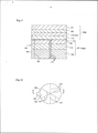
A figura 27 é uma vista em seção de explicação de uma parte principal que mostra uma estrutura laminada de um corpo de recipiente.Fig. 27 is an explanation section view of a main part showing a laminated structure of a container body.
A figura 28 é uma vista em perspectiva de um componente de funil de acordo com uma sexta modalidade da presente invenção.Figure 28 is a perspective view of a funnel component according to a sixth embodiment of the present invention.
A figura 29 é uma vista em seção tomada ao longo da linha A2-A2’ na figura 28.Figure 29 is a sectional view taken along line A2-A2 'in figure 28.
A figura 30 é uma vista em perspectiva mostrando um estado em que um componente de funil mostrado na figura 28 é fixado a um corpo de recipiente.Fig. 30 is a perspective view showing a state in which a funnel component shown in Fig. 28 is attached to a container body.
A figura 31 é uma vista em perspectiva de uma embalagem de acordo com uma sexta modalidade.Figure 31 is a perspective view of a package according to a sixth embodiment.
A figura 32 é uma vista em seção tomada ao longo da linha B2-B2’ na figura 31.Figure 32 is a sectional view taken along line B2-B2 'in figure 31.
A figura 33 é uma vista plana mostrando outro exemplo de nervuras fornecidas no interior de uma parte de abertura no lado de abertura menor de um funil.Fig. 33 is a plan view showing another example of ribs provided inside an opening part on the smaller opening side of a funnel.
A figura 34 é uma vista em perspectiva de uma embalagem tendo uma tampa de acordo com uma sétima modalidade da presente invenção.Figure 34 is a perspective view of a package having a lid according to a seventh embodiment of the present invention.
A figura 35 é uma vista superior de uma embalagem mostrada na figura 34.Fig. 35 is a top view of a package shown in Fig. 34.
A figura 36 é uma vista em seção tomada ao longo da linha A3-A3’ na figura 35.Figure 36 is a sectional view taken along line A3-A3 'in figure 35.
A figura 37 é uma vista traseira de uma tampa mostrada na figura 34.Fig. 37 is a rear view of a cover shown in Fig. 34.
A figura 38 é uma vista em seção tomada ao longo da linha B3-B3’ na figura 37.Figure 38 is a sectional view taken along line B3-B3 'in figure 37.
A figura 39 é uma vista em perspectiva de uma embalagem tendo uma tampa de acordo com uma oitava modalidade da presente invenção.Fig. 39 is a perspective view of a package having a lid according to an eighth embodiment of the present invention.
A figura 40 é uma vista em seção tomada ao longo da linha C3-C3’ na figura 39.Figure 40 is a sectional view taken along line C3-C3 'in figure 39.
Descrição dos caracteres de referência 1 embalagem 2 recipiente 3 membrana 5 pó 7 recipiente 8 componente de funil 10 corpo de recipiente 11 extremidade aberta 17 parede lateral 20 funil 101 recipiente de uso de reenchimento 102 corpo de recipiente 102A parte de abertura 103 tremonha 104 cobertura 104A parte de camada inferior 104B parte de camada superior 105 tampa de proteção 106 parte enrolada 106A diferença de nível 5 107 camada mais interna 108 camada de vedante 110 camada de folha metálica 111 camada exterior 113 parte fraca de resistência 10 114 folha de alumínio 118 camada de agente de liberação 118A superfície de liberação 119 pote 130 camada de adesivo 15 131 borda 133 extremidade 136 camada de papel 201 componente de funil 210 recipiente 20 211 embalagem 220 funil 221, 222 parte de abertura 223 parte afilada 224 primeira parte reta 25 225 parte de guia 226 segunda parte reta 227 parte saliente 228 nervura 229 elo 30 230 parede lateral 231 abertura 232 parte de pilar 233 parte de fixação 234 canto 35 240 nervura 241 face extrema de nervura 250 corpo de recipiente 260 conteúdo 270 membrana 301 embalagem 302 recipiente 303 membrana 304 tampa 309 linha de corte 310 corpo de recipiente 312 flange 320 funil 321 parte de abertura 330 placa superior 331 parede lateral 332a a 332h nervuras radiais 334a a 334h nervuras transversais 335a 335h nervuras transversais 336 encaixe 337a a 337d protuberâncias 339 fenda 340 protuberânciaDescription of the
Primeiramente, uma configuração básica de uma embalagem de acordo com a presente invenção é descrita abaixo com referência às figuras 1 a 7.First, a basic configuration of a package according to the present invention is described below with reference to figures 1 to 7.
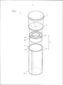
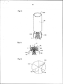
A figura 1 é uma vista em perspectiva mostrando uma configuração esquemática de uma embalagem de acordo com a presente invenção. A figura 2 é uma vista em perspectiva detalhada de uma embalagem mostrada na figura 1. A figura 3 é uma vista em seção tomada ao longo da linha lll-lll na figura 1.Figure 1 is a perspective view showing a schematic configuration of a package according to the present invention. Figure 2 is a detailed perspective view of a package shown in figure 1. Figure 3 is a sectional view taken along the line ll-lll in figure 1.
Uma embalagem 1 embala material de forma em pó, granular ou líquida e é utilizada como uma embalagem de uso de reenchimento para reencher outro recipiente de conservação com conteúdo. A embalagem 1 tem: um recipiente 2; conteúdo 5 cheio no recipiente 2; e uma membrana 3 para fechar uma extremidade aberta 11 do recipiente 2. Além disso, o recipiente 2 é dotado de uma sobretampa 4 formada de polietileno de alta densidade (HDPE), polipropileno (PP) ou similar para proteger a membrana 3. O conteúdo 5 não é limitado aos específicos desde que tenham fluidez. Desse modo, o recipiente 2 de acordo com a presente invenção é aplicável a vários tipos de materiais como pó, grânulos e líquido.A
O recipiente 2 tem: um corpo de recipiente no formato de cilindro 10 cuia extremidade é aberta; e um componente de funil 8 incluindo um funil 20 acomodado no interior do corpo de recipiente 10.The
O corpo de recipiente 10 tem uma parede lateral 17, uma parte inferior 18, e uma extremidade aberta 11. Na presente modalidade, o corpo de recipiente 10 é formado em uma forma tubular por arredondar um material de folha de formato retangular de modo a sobrepor o material em parte e então ligar as porções sobrepostas entre si. A patê inferior 16 do corpo de recipiente 10 é construído de: uma placa de base 19 de formato circular; e uma parte dobrada 18 para apertar e reter a parte de periferia externa da placa de base 19. Por outro lado, na extremidade aberta 11 do corpo de recipiente 10, uma parte da parede lateral 17 é flexionada para fora e enrolada anularmente de modo que um enrolamento 12 é formado.The
O material de formação para o corpo de recipiente 10 não é limitado a um específico. Entretanto, a partir da perspectiva de redução de peso do recipiente, facilidade de eliminação e economia de recurso, um material composto principalmente de papel é preferível. Como exemplo, na aplicação de embalar alimento, um material em folha pode ser utilizado que é formado por laminar, na ordem do lado de superfície interna do corpo de recipiente 10, polietileno de baixa densidade (LDPE), tereftralato de polietileno (PET), uma folha de alumínio e papel e que tem uma elevada propriedade de barreira de gás (uma propriedade de cortar oxigênio, vapor de água e componentes voláteis de origem de conteúdo, como componentes aromáticos, em particular).The forming material for the
O componente de funil 8 indica um componente construído de: um funil tendo uma parte cujo diâmetro diminui em direção a uma extremidade; e membros integrados ao funil. O componente de funil 8 ilustrado nas figuras 1 a 3 tem: um funil 20; e uma parede lateral 22 do formato cilíndrico conectado à parte de abertura maior do componente de funil 8. O componente de funil 8 é inserido no interior da extremidade aberta 11 do corpo de recipiente 10, e então adaptado em um recipiente de acomodação 10. Como descrito posteriormente, o funil 20 é fornecido para permitir fácil reenchimento de conteúdo 5 em outro recipiente, e é disposto de tal modo que seu diâmetro diminui em direção à extremidade aberta 11.0 ângulo de afilamento α do funil 20 é estabelecido apropriadamente em correspondência à fluidez do conteúdo. Quando o conteúdo é pó, o ângulo de afilamento é ajustado para ser pelo menos 20° a 45° e, mais preferivelmente, 20°.The
O componente de funil 8 pode ser moldado integralmente, por exemplo, com material de resina como HDPE e PP, ou alternativamente pode ser construído por conectar entre si um funil 20 e uma parede lateral 22 formada separadamente de papel, resina, resina misturada com papel ou similar. Quando resina ou resina misturada com papel é utilizada, o componente de funil 8 pode ser formado, por exemplo, por moldagem por injeção. Os formatos e o arranjo de fixação do funil 20 e o componente de funil 8 não são limitados ao exem- pio mostrado nas figuras 1 a 3. Isto é, vários tipos de variações podem ser empregados.The
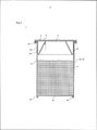
A figura 4 é uma vista plana da membrana mostrada na figura 2. A figura 5 é uma vista em seção tomada ao longo da linha V-V na figura 4.Figure 4 is a plan view of the membrane shown in Figure 2. Figure 5 is a sectional view taken along line V-V in Figure 4.
A membrana 3 é utilizada para vedar a extremidade aberta 11 do recipiente 2 após o recipiente 2 ser cheio de material. De acordo com a aplicação do recipiente 2, um material de folha composto de uma camada única ou alternativamente um material de folha fabricado por laminar uma pluralidade de camadas pode ser empregado. Em um caso em que o conteúdo do recipiente 2 é alimento ou similar, é preferível que a membrana 3 seja formada de um material tendo uma propriedade de barreira de gás.The
Especificamente, como mostrado na figura 5, a membrana 3 é construída de: uma camada vedante 31 para vedar o recipiente 2; uma camada de resina 32 laminada na camada vedante 31; e uma camada de folha metálica 34 ligada na camada de resina 32 através de uma camada de adesivo 33. Em uma exemplo, a camada vedante 31 pode ser formada de polietileno, a camada de resina 32 pode ser formada de tereftalato de polietileno (PET), e a camada de folha metálica 34 pode ser formada de alumínio. O número de camadas laminadas e o método de laminação para as camadas constituindo a membrana 3 não são limitadas a específicos e podem ser arbitrários.Specifically, as shown in figure 5, the
Na membrana 3, seis linhas de corte 30 estendendo radialmente a partir do centro são formadas de modo a permitir quebra quando uma tensão excedendo uma magnitude predeterminada é causada por uma força de pressão a partir do exterior. Nas linhas de corte 30, como mostrado nas figuras 4 e 5, a camada de vedante 31 e a camada de resina 32 individualmente são cortadas na direção de espessura da membrana 3. Além disso, na direção de extensão da membrana 3, as linhas de corte 30 são formadas na forma de linhas tracejadas.In the
As linhas de corte 30 são fornecidas para ajustar a resistência de quebra da membrana 3. Desse modo, em resposta a uma força de pressão aplicada sobre a membrana 3, o número de linhas, seus formatos, e o comprimento e profundidade da parte de corte podem ser estabelecidos arbitrariamente. O número ideal de linhas de corte 30 está compreendido na faixa de 3 a 10 contado radialmente a partir do centro. As linhas de corte 30 podem ser linhas retas ou linhas alternativamente curvas. Além disso, na direção de extensão da membrana 3, as linhas de corte 30 não necessitam ser necessariamente perfuração de formato de linha tracejada, e podem ser fabricadas na forma de linhas cheias.The cut lines 30 are provided to adjust the breaking strength of the
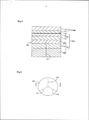
A figura 6 é uma vista em perspectiva mostrando uma situação de uso de uma embalagem de acordo com a presente invenção. A figura 7 é uma vista em seção tomada ao longo da linha VII-VII na figura 6. Mais especificamente, nas figuras 6 e 7, a parte (a) mostra o estado da membrana antes de quebra, enquanto a parte (b) mostra o estado da membrana após quebra.Figure 6 is a perspective view showing a situation of using a package according to the present invention. Figure 7 is a sectional view taken along line VII-VII in figure 6. More specifically, in figures 6 and 7, part (a) shows the state of the membrane before breaking, while part (b) shows the state of the membrane after breaking.
Quando outro recipiente 7 deve ser cheio novamente com o conteúdo 7 na embalagem 1, primeiramente, como mostrado nas figuras 6(a) e 7(a), o recipiente 2 cuja sobretam- pa foi removido é invertido, e então a membrana 3 é induzida a encostar contra a parte de abertura do recipiente de conservação 7. Nesse momento, para que a parte de abertura no lado de abertura menor do funil 20 deva ser localizado na região da parte de abertura do recipiente de conservação 7, o centro do recipiente 2 é alinhado com o centro do recipiente de conservação 7.When another container 7 must be refilled with the contents 7 in the
Então, a parte inferior da embalagem 1 é prensada para baixo na direção de seta na figura . nesse momento, de acordo com a força de pressão do recipiente 2, a membrana 3 recebe uma força de pressão a partir do funil 20 e a parte de abertura do recipiente 7. Então, quando a tensão na membrana 3 excede uma resistência de quebra predeterminada, a membrana 3 é quebrada como mostrado nas figuras 6(b) e 7(b). quando a membrana 3 é quebrada, de acordo com a força de pressão aplicada sobre o recipiente 2, o funil 20 é inserido no recipiente 7. A membrana quebrada 3 é dobrada em um espaço formado entre o funil 20 e a parede lateral 22. Como resultado, um estado é realizado em que a parte de abertura no lado externa do funil 20 é aberta de forma ampla. Desse modo, de acordo com a gravidade, o conteúdo 5 flui para dentro do recipiente 7 ao longo do afilamento do funil 20.Then, the bottom of
Como descrito acima, de acordo com o recipiente 2 da presente invenção e a embalagem 1 utilizando isso, quando a membrana 3 é induzida a encostar contra a parte de abertura do recipiente 7 e então o recipiente 2 é pressionado em direção ao recipiente de conservação 7, a parte de abertura do funil 20 é inserida no recipiente de conservação 7 quase simultaneamente com a quebra da membrana 3. Desse modo, o conteúdo 5 no recipiente 2 é guiado para o interior do recipiente de conservação 7 pelo funil 20. Isso evita espalhamento ou queda do conteúdo 5 no momento de trabalho de reenchimento. Desse modo, o recipiente 2 e a embalagem 1 de acordo com a presente modalidade permitem reen-chimento fácil de conteúdo.As described above, according to the
Além disso, até o momento de reenchimento incluindo a duração de armazenagem e transporte, a vedação é mantida pela membrana 3 e recipiente 2. Desse modo, a qualidade (aroma, sabor e similar) do conteúdo pode ser mantida até o momento imediatamente antes do uso.In addition, until the time of refilling including the duration of storage and transportation, the seal is maintained by
A estrutura de um material de cobertura (membrana) é descrita abaixo na primeira a terceira modalidades.The structure of a cover material (membrane) is described below in the first to third embodiments.
Aqui, a presente invenção é basicamente aplicável a coberturas de tipos arbitrários que têm uma propriedade de barreira e que são utilizadas para vedar um copo de papel e aberto por quebra da cobertura. Desse modo, obviamente, a presente invenção não é limitada às estruturas descritas nas seguintes modalidades.Here, the present invention is basically applicable to covers of arbitrary types that have a barrier property and that are used to seal a paper cup and open by breaking the cover. Thus, of course, the present invention is not limited to the structures described in the following embodiments.
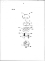
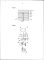
Primeiramente, como mostrado nas figuras 10 e 11, um recipiente de uso de reenchimento 101 tem um corpo de recipiente 102, uma tremonha 103, uma cobertura 104 tendo uma propriedade de barreira, e uma tampa de proteção 105.First, as shown in figures 10 and 11, a
O corpo de recipiente 102 tem um formato cilíndrico dotado de uma parte inferior. Como seu material de substrato, um pedaço de papel retangular é adotado. Esse cilindro fabricado de papel é composto de uma folha compósita formada por laminação, na ordem da camada mais externa em direção ao interior, papel, polietileno, folha de analumínio, teref- talato de polietileno e polietileno. Isso é para cortar umidade e ar. A resina de polietileno na superfície interna é para assegurar aderência com a cobertura 104. As técnicas de processamento a serem adotadas aqui são aquelas conhecidas de forma pública. Por exemplo, técnicas em geral em laminação e aplicação são adotadas. Na fabricação do corpo de recipiente 102, um pedaço de papel retangular cuja superfície foi tratada como descrito acima é arredondada em um formato cilíndrico. Então, os lados direito e esquerdo são sobrepostos. Após isso, as partes sobrepostas servindo como regiões de colagem são apropriadamente ligadas entre si. O meio adotado de ligação pode ser adesivos, vedação a calor ou outro meio apropriado conhecido publicamente, então, como mostrado nas figuras 10 e 11, na extremidade superior, uma parte enrolada anular (simplesmente uma parte enrolada, a seguir) 106 é formada que é anularmente enrolada para fora. Desse modo, na superfície superior da parte enrolada 106, na parte sobreposta dos dois lados, uma diferença de nível 106A surge inevitavelmente nas direções para cima e para baixo. Uma vez que a diferença de nível 106A poderia degradar a propriedade de vedação, sua solução é importante.The
Como mostrado nas figuras 10 e 11, a tremonha 103 de formato cilíndrico é encaixada na parte de abertura 102A do corpo de recipiente 102. A tremonha 103 é formada da mesma matéria prima que aquela do corpo de recipiente 102 ou alternativamente de um material de resina apropriado como polietileno de alta densidade (HDPE) e polipropileno cuja espessura é ajustada para ser 0,8 mm. O ambiente em volta da tremonha 103 tem uma parede em elevação reta 103A não cotada de um flange externo na extremidade superior. Em um estado em que a extremidade superior é localizada na mesma altura que a extremidade superior da parte de abertura 102A do corpo de recipiente 102, isto é, como a face de extremidade superior 106B da parte enrolada 106, a parede em elevação 103A é encaixada na parte de abertura 102A. além disso, a partir da borda de extremidade inferior da parede em elevação 103A, um funil 103B inclinado gradualmente em direção à parte superior e central é fornecido integralmente. A seguir, o ângulo de afilamento α do funil 103B é definido para ser pelo menos 20° a 45° e, mais preferivelmente, 20 °.As shown in figures 10 and 11, the
A tremonha 103 é encaixada na parte de abertura 102A em um estado em que a extremidade superior do funil 103B é localizado quase na mesma altura que as extremidades superiores da parede em elevação 103A e a parte de abertura 102A do corpo de recipiente 102. Isto é, o alinhamento é executado de tal modo a permitir que esses sejam dispostos aproximadamente no mesmo plano. Após ser encaixada, a tremonha 103 é apropriadamente fixada na superfície periférica interna da parte de abertura 102A. O meio adotado de fixação pode ser um apropriadamente mais preferível como vedação a calor, soldagem em alta frequência de adesivos.The
A extremidade superior da tremonha 103 é vedada pela abertura 104 tendo uma propriedade de barreira. Como mostrado na figura 8, a cobertura 104 tendo uma propriedade de barreira é composta de uma folha compósita fabricada por laminar uma parte de camada inferior 104A e uma parte de camada superior 104B com uma camada de agente de liberação (a ser descrita posteriormente) que liga essas duas partes em um modo despren- dível. Primeiramente, a parte de camada inferior 104A é construída de: uma camada mais interna 107 fabricada de uma camada de resina contendo uma camada de vedante 108 de polietileno; e uma camada de folha metálica 110 ligada no lado externo da camada de resina da camada mais interna 107 através de uma camada de adesivo (a ser descrita posteriormente). A camada externa 111 servindo como a parte de camada superior 104B é construída principalmente de papel. A seguir, a parte de camada superior 104B é ligada sobre o lado externo da camada de folha metálica 110 da parte de camada inferior 104A através de uma camada de agente de liberação 118 (a ser descrita posteriormente). Além disso, na camada mais interna 107, uma pluralidade de partes fracas de resistência 113 é fornecida radialmente a partir do centro. A seguir, as partes fracas de resistência 113 permitem que a camada de folha metálica 110 seja quebrada facilmente juntamente com a camada mais interna 107 de modo a permitir abertura fácil.The upper end of the
A camada mais baixa da camada mais interna 107 é uma camada de vedante 108 de polietileno (polietileno de baixa densidade linear: LLDPE) de 40 pn. a seguir, na superfície superior da camada de vedante 108 de polietileno, tereftalato de polietileno (PETO 109 de 12 |im é laminado através de um filme d resina extrusada 112 de polietileno (polietileno de baixa densidade: LDPE) de 20 p.m. Além disso, uma folha de alumínio 114 de 9 |im é adaptada como a folha metálica servindo como o substrato da camada de folha metálica 110. Na superfície inferior da folha de alumínio 114, o tereftalato de polietileno (PET) 109 da camada mais interna 107 é ligada e laminada através do filme de resina extrusada 115 de polietileno (polietileno de baixa densidade: LDPE) de 15 jim. Desse modo, o filme de resina extrusada 115 serve como uma camada de adesivo entre a camada mais interna 107 e a camada de folha metálica 110. Além disso, a camada externa 111 servindo como a parte de camada superior 104B ligada e laminada sobre o lado externo da folha de alumínio 114 é composta de uma camada de papel 116 tendo um peso base de 52,3 g/m2. A seguir, um filme de resina extrusada de polietileno (polietileno de baixa densidade: LDPE) 117 de 15 jim é laminado na superfície inferior da camada de papel 116. O filme de resina extrusada 117 e a folha de alumínio 114 são ligadas entre si através de uma camada de agente de liberação 118 composta de verniz de desprendimento ou similar, de modo que uma folha compósita é formada. Como o meio de processamento dessa folha compósita, técnicas publicamente conhecidas são adotadas além das mencionadas acima. Técnicas gerais em laminação e aplicação são adotadas. Além disso, como a camada de agente de liberação 118, verniz de desprendimento (borracha clorada é aplicada uniformemente) ou verniz de adesivo (borracha clorada é aplicada na forma de pontos) é adotada. O verniz de desprendimento adotado pode ser uma combinação de um ou mais tipos e duas ou mais camadas. Além disso, o modo de aplicação pode ser uniforme ou alternativamente na forma de pontos.The lowest layer of the
A espessura da camada de vedante 108 de polietileno é selecionada apropriadamente na faixa, preferivelmente de 30 a 200 jim. A espessura do filme de resina extrusado 112 de polietileno na camada de vedante 108 é selecionado apropriadamente na faixa, preferivelmente de 5 a 50 jim. além disso, a folha de alumínio 114 da camada de folha metálica 110 é selecionada apropriadamente a partir daqueles tendo uma espessura compreendida na faixa de 6 a 50 jim.comrelação ao filme de resina extrusada 115 de polietileno da superfície inferior da folha de alumínio 114, uma apropriada é selecionada entre aquelas tendo um valor compreendido na faixa de 5 a 50 jim. com relação à camada de papel 116, uma apropriada é selecionada daquelas tendo um valor compreendido na faixa, preferivelmente de 30 a 200 g/m2 em peso base. Além disso, com relação ao filme de resina extrusada 117 de polietileno (polietileno de baixa densidade: LDPE) laminado na superfície inferior da camada de papel 116, uma apropriada é selecionada daquelas tendo um valor compreendido na faixa de 5 a 50 jim. com relação à camada de agente de liberação 118, verniz de desprendimento ou verniz de adesivo é adotado. Verniz de desprendimento é aplicado uniformemente, enquanto verniz de adesivo é aplicado na forma de pontos.The thickness of the
Aqui, com relação à tereftalato de polietileno (PET) 109 laminado na camada de vedante 108 de polietileno, um apropriado é selecionado daqueles tendo um valor compreendido na faixa de 5 a 50 jim. entretanto, o tereftalato de polietileno (PET) 109 pode ser fornecido somente quando necessário.Here, with respect to polyethylene terephthalate (PET) 109 laminated to the
O formato geral da cobertura 104 é um círculo tendo quase o mesmo diâmetro que a parte de abertura 102A do corpo de recipiente 102, especificamente, aproximadamente 90 mm 0 como mostrado nas figuras 10 e 11. A seguir, sua parte de borda 131 é apropriadamente ligada sobre a extremidade superior da parte de abertura 102A do corpo de recipiente 102, isto é, na face de extremidade superior 106B da parte enrolada 106. Em geral, essa ligação é obtida por vedação a calor. Aqui, a ligação pode ser executada sobre a face extrema superior da parede em elevação 103A da tremonha 103. Entretanto, nessa configuração, a cobertura 104 meramente contata com a borda superior do funil 103B da tremonha 103, isto é, com a borda superior da parte de abertura 103B1.The general shape of the
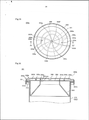
Além disso, na cobertura 104 tendo uma propriedade de barreira, como mostrado nas figuras 8 a 10, linhas de corte ou perfuração (perfuração no exemplo na figura 1) servindo como três partes fracas de resistência 113 são fornecidas em direções radiais a partir do centro em intervalos aproximadamente regulares na direção circunferencial. A faixa de fornecimento é para a camada mais interna 107 e o filme de resina extrusado 115 de polietileno. As linhas de corte ou perfuração servindo como as partes fracas de resistência 113 permitem que a camada de folha metálica 110 seja quebrada facilmente juntamente com a camada mais interna 107 de modo a permitir fácil abertura. Nas linhas de corte ou perfuração, como mostrado na figura 9, o comprimento de cada perfuração é definido como sendo 9 mm enquanto a conexão é definida como sendo 1 mm. Aqui, o valor três para o número de linhas é a exigência míniam para obter o objetivo desejado da presente invenção. Além disso, o limite superior para um valor preferível do número de linhas é dez, embora isso dependa do tamanho da cobertura 104. Em contraste, o número de linhas igual a ou maior do que 11 causa a preocupação de enfraquecimento de resistência da cobertura 104, e consequentemente não é preferível. De forma ideal, o número de linhas é 3 a 10 (6 nos exemplos mostrados na figura 16).In addition, on the
Na tampa de proteção 105, o mesmo material como aquele do corpo de recipiente 102 ou alternativamente uma resina apropriada como polietileno de alta densidade (HDPE) e polipropileno cuja espessura é definida com sendo aproximadamente 0,8 mm é adotado. Como mostrado nas figuras 10 e 11, a tampa de proteção 105 é encaixada sobre a parte de abertura 102A do corpo de recipiente 102 de modo a proteger a cobertura 104 e manter o lado interno higiênico.In the
O trabalho de carregar café instantâneo em pó P no recipiente de uso de reenchimento 101 de acordo com a presente invenção é executado, em geral, através da parte de abertura 103B1 da tremonha 103.The work of loading instant coffee powder P into the
A seguir, um método de uso do recipiente de uso de reenchimento 101 tendo a configuração acima mencionada de acordo com a primeira modalidade é descrito abaixo.In the following, a method of using the
Primeiramente, a tampa de proteção 105 é removida. A seguir, a tampa 104 é exposta. Desse modo, a borda da camada externa 111 servindo como a parte de camada superior 104B é apertada e puxada para cima com os dedos. Como resultado de puxar para cima, a camada externa 111 é removida da folha de alumínio 114 da camada de folha metálica inferior 110 no nível da camada de agente de liberação 118 servindo como uma camada de desprendimento. Nesse momento, som de desprender é gerado. Isso provê forte impressão de uma propriedade virgem. Então, como mostrado nas figuras 12 e 13, o corpo de recipiente 102 é invertido. Então, o funil 103B da tremonha 103 é induzido a encostar contra uma parte de abertura cilíndrica 119A do pote 119 servindo um exemplo de um recipiente de reenchimento em uma posição que permite encaixe. O café instantâneo P no corpo de recipiente 102 já fluiu para baixo para dentro do funil 103B a partir da tremonha 103, porém é retido pela cobertura 104. Então, como mostrado nas figuras 14 e 15, uma força de pressão é aplicada sobre o corpo de recipiente 102 de tal modo que o funil 103B é empurrado para dentro da parte de abertura 119A do pote 119. Essa força de pressão atua como uma força para fazer com que a parte de abertura 119A do pote 119, em geral, a parte cilíndrica que se eleva cilindricamente a partir do corpo, pressione e quebre a cobertura 104. Isto é, a força atua como uma força para fazer com que a parte de abertura 119A do pote 119 empurre para cima a cobertura 104 e empurrando isso para um espaço triangular S em uma vista em seção transversal formada entre a parede em elevação 103A e o funil 103B da tremonha 103. Uma vez que a perfuração servindo como as partes fracas de resistência 113 é fornecida radialmente, a cobertura 104 que recebe essa força de pressão é quebrada e dividida em uma pluralidade de peças fendilhadas ao longo da perfuração rapidamente e notavelmente facilmente. Ao mesmo tempo, o funil 103B entra na parte de abertura 119A do pote 119. Como resultado, a parte de abertura 103B1 do funil 103B da tremonha 103 é aberta. Desse modo, com a ação de guiar em direção ao centro pelo funil 103B da tremonha 103, o café instantâneo P no corpo de recipiente 102 flui para baixo para dentro do pote 119 imediatamente. Após conclusão do reenchimento do pote 119, o recipiente de uso de reenchimento 101 é descartado. O numeral 102B na figura indica a parte inferior do corpo de recipiente 102.First, the
Desse modo, o funil 103B encaixado na parte de abertura 119A do pote 119 guia e faz com que o café instantâneo P flua para baixo para dentro do pote 119 sem cair fora do pote 119. Além disso, uma possibilidade é evitada de que o conteúdo seja exposto desnecessariamente a ar aberto. Desse modo, uma possibilidade de que o arome o sabor sejam degradados também pode ser evitada o máximo possível.In this way, funnel 103B fitted into the
Como resultado de um teste de desempenho para a cobertura obtida, a parte central foi pressionada e quebrada satisfatoriamente. Aqui, sua resistência de quebra por pressão era de 100 N ou mais baixa. Alem disso, em um teste de checagem para imersão de líquido na diferença de nível 106A da parte de abertura 102A empregando um corpo de papel, a ocorrência de vazamento não foi detectada. Além disso, mesmo quando amostras foram armazenadas em temperaturas elevas, nenhum exemplo foi encontrado de que a cobertura é espontaneamente desprendida da parte de abertura 102A do copo de papel. Além disso, uma propriedade de barreira satisfatória foi obtida na cobertura total em comparação com uma cobertura de alumínio. A geração de odor não foi detectada em comparação com uma cobertura de fusão a calor. Além disso, um teste de transporte equivalente a transporte de 2000 km foi realizado de modo que a situação de quebra da perfuração foi pesquisada. Como resultado, em virtude da presença da camada externa 111 composta principalmente de papel, a quebra na perfuração não foi gerada em nenhum amostra.As a result of a performance test for the coverage obtained, the central part was pressed and broken satisfactorily. Here, its pressure breaking resistance was 100 N or lower. In addition, in a check test for liquid immersion in the
Como tal, a camada mais interna da cobertura 104 é dotada da camada de vedante 108 de polietileno (polietileno com baixa densidade linear: LLDPE). Desse modo, independente da presença da diferença de nível 106A na parte de abertura 102A que é específica a um copo de papel, mesmo quando a parte de abertura 102A do copo de papel é diretamente vedada pela cobertura 104, vedação satisfatória é obtida. Como resultado, hermeticidade satisfatória pode ser realizada. Além disso, uma vez que fusão a calor não é adotada, uma propriedade de vedação estável é obtida enquanto a influência de odor pode ser eliminada. Além disso, apesar da cobertura 104 ter as partes fracas de resistência 113 no lado interno, a camada de folha metálica 110 e a camada mais interna 107 no lado interno podem ser protegidas de forma segura a partir de um choque externo ou uma força de pressão. Desse modo, a cobertura 104 tendo elevada segurança foi fornecida. Adicionalmente, antes do trabalho de pressão e quebra da cobertura 104 ao longo das partes fracas de resistência 113, quando a camada externa 111 composta principalmente de papel é desprendida, som leve de desprendimento é geral. Isso provê impressão forte de uma propriedade virgem.As such, the innermost layer of the
Como mostrado na figura 17, uma cobertura 104 tendo uma propriedade de barreira descrita em uma segunda modalidade é composta de uma folha compósita na qual uma parte de camada inferior 104A composta principalmente de uma camada vedante 108 de polietileno e uma parte de camada superior 104B composta principalmente de uma camada de folha metálica 110 são laminadas entre si através de uma camada de agente de liberação 118. A camada mais baixa da camada mais interna 107 é uma camada de vedante 108 de polietileno (polietileno de baixa densidade linear: LLDPE) de 40 p.m. na superfície superior da camada de vedante 108 de polietileno, tereftalato de polietileno (PET) 109 de 12 p.m é laminado através de um filme de resina extrusada 112 de polietileno (polietileno de baixa densidade: LDPE) de 20 p.m. Além disso, uma folha de alumínio 114 de 7 p.m é adotada como a folha metálica que serve como o substrato da camada de folha metálica 110. Um filme de resina extrusada de polietileno (polietileno de baixa densidade: LDPE) 115 de 20 p.m é laminado na superfície inferior da folha de alumínio 114. Por outro lado, na superfície superior, tereftalato de polietileno (PET) 121 de 12 p.m é laminado através de um filme de resina extrusada 120 de polietileno (polietileno de baixa densidade: LDPE) de 15 p.m. Então, o tereftalato de polietileno (PET) 109 da camada mais baixa 107 e o filme de resina extrusada 115 de polietileno (Polietileno de baixa densidade: LDPE) da superfície mais baixa da parte de camada superior 104B são ligados entre si através da camada de agente de liberação 118. Como a camada de agente de liberação 118, verniz de desprendimento (borracha clorada é aplicada uniformemente) ou verniz de adesivos (borracha clorada é aplicada na forma de pontos) é adotado. O verniz de desprendimento adotado pode ser uma combinação de um ou mais tipos e duas ou mais camadas. Além disso, o modo de aplicação pode ser uniforme ou alternativamente na forma de pontos. Na configuração adotada na presente modalidade, na superfície superior do tereftalato de polietileno (PET) 109 da camada mais interna 107, verniz de desprendimento de borracha clorada é primeiramente aplicado uniformemente e então verniz de adesivos de borracha clorada é aplicado no mesmo na forma de pontos.As shown in figure 17, a
Na configuração acima mencionada, na parte de camada inferior 104A, uma folha de alumínio, um filme de plástico, ou um material laminado de papel ou similar pode ser adotado. Além disso, no lugar desses, a camada de vedante 108 de polietileno (polietileno de baixa densidade linear: LLDPE) pode ser adotada individualmente. Além disso, também na parte de camada superior 104B, uma única folha de alumínio, ou um material laminado composto de um filme de plástico e papel é adotada dependendo da necessidade. A folha de alumínio é selecionada entre aquelas compreendidas na faixa de 6 a 50 gm. o filme de resina extrusada 115 de polietileno (polietileno de baixa densidade: LDPE) da superfície inferior de folha de alumínio 114 é selecionado daqueles compreendidos na faixa de 5 a 50 p.m.In the aforementioned configuration, in the
Além disso, a camada de agente de liberação 118 pode ser composta de um filme de desprendimento fácil. A espessura é estabelecida como sendo 20 a 100 p.m, enquanto a resistência de adesivo com o filme de resina extrusada 115 de polietileno (polietileno de baixa densidade: LDPE) na superfície mais baixa da parte de camada superior 104B é estabelecida como sendo 0,1 a 8 N.In addition, the
Além disso, na cobertura 104 a partir da parte de camada inferior 104A até a parte de camada superior 104B, uma lingueta 122 é fornecida que se projeta para fora em uma direção radial a partir da boda da cobertura 104. A lingueta 122 faz com que a parte de camada superior 104B seja desprendida da parte de camada inferior 104A na camada de agente de liberação 118, através das linhas de corte (perfuração) 123 fornecidas entre a lingueta e a borda da parte de camada inferior 104A. Tal lingueta 122 pode ser fornecida na primeira modalidade descrita acima.In addition, in the
Além disso, como mostrado na figura 18, o formato da cobertura 104 é basicamente similar àquele da primeira modalidade exceto pela configuração da lingueta 122. A diferença é que seis linhas de perfuração servindo como as partes fracas de resistência 113 são fornecidas radialmente em intervalos iguais a partir do centro em direção à borda. Além disso, um copo de papel é adotado no qual o corpo de recipiente 102 tem uma estrutura de alumínio em camadas.In addition, as shown in figure 18, the shape of the
Os resultados de teste de desempenho para a cobertura são como a seguir. Isto é, os resultados similares àqueles da primeira modalidade foram obtidos em uma propriedade de abertura, uma propriedade de vedação, uma propriedade de barreira, a presença ou ausência de odor, proteção para as partes fracas de resistência, uma propriedade virgem. Além disso, por utilizar a lingueta 122, a parte de camada superior pode ser desprendida adequadamente, e consequentemente obteve-se uma sensação de desprendimento satisfatória.The performance test results for coverage are as follows. That is, the results similar to those of the first modality were obtained in an opening property, a sealing property, a barrier property, the presence or absence of odor, protection for weak parts of resistance, a virgin property. In addition, by using the
Como mostrado na figura 19, uma cobertura 104 tendo uma propriedade de barreira descrita em uma terceira modalidade também é composta de uma folha compósita na qual uma parte de camada inferior 104A composta principalmente de uma camada de vedante 108 de polietileno e uma parte de camada superior 104B composta principalmente de uma camada de folha metálica 110 são laminadas entre si através de uma superfície de liberação 118A. a camada mais baixa da camada mais interna 107 é uma camada de vedante 108 de polietileno (polietileno de baixa densidade linear: LLDPE) de 40 p.m. um filme de polipropile- no orientado (OPP) 124 de 20 pm foi laminado na superfície superior da camada de vedante 108 de polietileno utilizando adesivos laminados secos 125, de modo que um filme laminado como a parte de camada inferior 104A foi obtido. Então, seis linhas de perfuração, como partes fracas de resistência 113, foram fabricadas nas direções que se estendem radialmente a partir do centro desse filme laminado até a posição de vedação com o corpo de recipiente 102. O comprimento da perfuração foi de 9 mm, enquanto o comprimento de conexão foi de 1 mm. Na parte de camada superior 104B, a folha de alumínio 114 de 7 pm foi adotada como a camada de folha metálica 110. Além disso, na superfície superior da folha de alumino 114, tereftalato de polietileno (PET) de 12 pm foi laminado através de um filme de resina extrusada 120 de polietileno (PE) de 20 pm. então, a superfície superior do filme de polipropileno orientado (OPP) 124 da camada mais baixa 107 e a superfície inferior da folha de alumínio 114 foram extrusadas e laminadas com um filme de resina 126 de polietileno (PE). Como resultado, um filme laminado de duas camadas que pode ser desprendido pode ser obtido. Esse filme laminado foi perfurado em um formato de círculo com lingueta tendo um tamanho especificado, de modo que a cobertura 104 foi obtida. O filme de resina 126 do polietileno extrusado (PE) e o filme de polipropileno orientado (OPP) 124 foram fabricados de tipos diferentes de resinas entre si. Desse modo, a adesão completa não ocorreu, e consequentemente a parte de camada superior 104B foi capaz de ser desprendida a partir da parte de camada inferior 104A na superfície de liberação 118A pela mão. Nessa terceira modalidade, como descrito acima, o filme de resina da camada mais superior da parte de camada inferior 104A e o filme de resina da camada mais inferior da parte de camada superior 104B foram fabricados de tipos diferentes de resinas entre si de modo que se obteve uma superfície facilmente desprendível. Como resultado, a configuração da camada de agente de liberação foi simplificada. Isso simplifica os trabalhos de processo e etapas na fabricação, e consequentemente reduz o custo.As shown in figure 19, a
Os resultados de teste de desempenho para a cobertura são como a seguir. Isto é, os resultados similares àqueles da primeira modalidade foram obtidos em uma propriedade de abertura, uma propriedade de vedação, uma propriedade de barreira, a presença ou ausência de odor, proteção para as partes fracas de resistência, uma propriedade virgem. Além disso, utilizando a lingueta 122, a parte de camada superior pode ser desprendida adequadamente, e consequentemente, sensação satisfatória de desprendimento foi obtida.The performance test results for coverage are as follows. That is, the results similar to those of the first modality were obtained in an opening property, a sealing property, a barrier property, the presence or absence of odor, protection for weak parts of resistance, a virgin property. In addition, using the
Para fins de testar os resultados acima mencionados, produtos de comparação foram fabricados.For the purpose of testing the results mentioned above, comparison products were manufactured.
Como mostrado na figura 20, o filme de polipropileno orientado (OPP) de uma espessura de 20 |im e o filme de polietileno (Polietileno de baixa densidade linear: LLDPE) de uma espessura de 40 pm foram laminados a seco entre si de modo que um filme laminado foi obtido. A seguir, seis linhas de perfuração tendo um comprimento de perfuração de 9 mm e um comprimento de conexão de 1 mm foram fabricadas no filme laminado por um cortador de pináculo nas direções se estendendo radialmente a partir do centro do material de cobertura circular até a posição de vedação, de modo que um filme de camada inferior foi obtido. Por outro lado, uma folha de alumínio de 7 pm foi ligada por laminação extrusada de polietileno (PE) de 15 pm, de modo que um filme superior foi obtido. Então, os filmes de camada superior e inferior foram laminados na superfície de filme de polipropileno orientado (OPP) acima mencionado através de um agente de revestimento de fixação, de modo que um filme laminado foi obtido. Então, esse filme laminado foi perfurado em um círculo tendo um tamanho especificado, de modo que um material de cobertura foi obtido.As shown in figure 20, the oriented polypropylene film (OPP) of a thickness of 20 µm and the polyethylene film (linear low density polyethylene: LLDPE) of a thickness of 40 pm were dry laminated to each other so that a laminated film was obtained. Next, six perforation lines having a perforation length of 9 mm and a connection length of 1 mm were made in the laminated film by a pinnacle cutter in the directions extending radially from the center of the circular cover material to the position sealing, so that a lower layer film was obtained. On the other hand, a 7 pm aluminum sheet was bonded by a 15 pm extruded polyethylene (PE) lamination, so that a superior film was obtained. Then, the top and bottom layer films were laminated to the aforementioned oriented polypropylene (OPP) film surface through a fixing coating agent, so that a laminated film was obtained. Then, this laminated film was perforated in a circle having a specified size, so that a covering material was obtained.
Cada material de cobertura obtido foi ligado e vedado sobre a borda da parte de abertura 102A do corpo de recipiente 102 que é descrito na primeira modalidade e contém pó de café instantâneo. Então, testes de desempenho foram realizados com relação à propriedade de abertura e a resistência a impacto de queda da cobertura.Each cover material obtained was bonded and sealed over the edge of the
Na inspeção para a propriedade de abertura, com relação a produto de acordo com a presente invenção, após a parte de camada superior 104B ser removida por aperto da lingueta 122, o reenchimento em uma garrafa de vidro foi executado. Além disso, no exemplo, de comparação, o reenchimento foi executado em um estado intacto. Então, a resistência de pressão foi medida no momento em que o produto é induzido a encostar contra a abertura de garrafa e quebra o material de cobertura.Upon inspection for the opening property, with respect to the product according to the present invention, after the
Como resultado de inspeção, a resistência de não vedação foi de 90 g na presente modalidade, e 130 g no exemplo de comparação. Isso mostrou que uma propriedade de abertura muito melhor foi obtida na presente modalidade.As a result of inspection, the non-sealing resistance was 90 g in the present modality, and 130 g in the comparison example. This showed that a much better opening property was obtained in the present modality.
Além disso, na inspeção em relação à resistência a impacto por queda, em cada da presente modalidade e exemplo de comparação, o recipiente foi deixado cair de uma posi- ção de 60 cm de altura em um estado em que a parte de abertura 102A do corpo de recipiente 102 foi vedado pelo material de cobertura. Então, a presença ou ausência de quebra iniciando a partir da perfuração foi verificada por inspeção visual.In addition, in the inspection in relation to the impact resistance to fall, in each of the present modality and comparison example, the container was dropped from a 60 cm height position in a state where the
Como resultado de inspeção, nenhuma quebra foi detectada tanto na presente modalidade como no exemplo de comparação mesmo após 10 vezes de queda. Desse modo, com relação à resistência a impacto por queda, a superioridade da presente modalidade não foi obtida.As a result of inspection, no break was detected either in the present modality or in the comparison example even after 10 times of a fall. Thus, with respect to resistance to impact by falling, the superiority of the present modality was not obtained.
Aqui, nas primeira a terceira modalidades, na extremidade superior da parede em elevação 103A da tremonha 103, um flange pode ser fornecido que é hermeticamente encaixado na borda de abertura do corpo de recipiente 102. Entre as funções da própria cobertura 104 descritas nas primeira a terceira modalidades descritas acima, as vantagens como propriedade de abertura, propriedade de retenção em temperatura elevada, propriedade de barreira, odor, e sensação de abertura, bem como a processabilidade e estabilidade das partes fracas de resistência 113, são totalmente obtidas de forma equivalente sem degradação.Here, in the first to third embodiments, at the upper end of the raised
Além disso, nas primeira a terceira modalidades, café instantâneo em pó é adotado como o conteúdo. Entretanto, outro fluido em pó de alimento ou não alimento pode ser adotado. Por exemplo, leite solúvel em água (leite em pó), cacau, chá, ou pó de uma combinação desses podem ser adotados. Além disso, purê de batata seco e outro alimento seco, pó de molho ou fonte, e pó de sopa, bem como toner para uma máquina de copiar pode ser adotado.In addition, in the first to third modalities, instant coffee powder is adopted as the content. However, another fluid powder of food or non-food can be adopted. For example, water-soluble milk (powdered milk), cocoa, tea, or powder from a combination of these can be adopted. In addition, dried potato puree and other dry food, sauce powder or source, and soup powder, as well as toner for a copy machine can be adopted.
Além disso, no lugar do pote 119, as modalidades podem ser aplicadas a um tanque de pó de café de máquina de fazer café, um recipiente de reenchimento de toner de uma máquina de copiar, e similar.In addition, in place of
As primeira a terceira modalidades justificam os seguintes itens 1 a 10 como o escopo de proteção da presente invenção. I.Uma cobertura tendo uma propriedade de barreira, compreendendo: uma parte de camada inferior incluindo uma camada mais interna e uma camada de folha metálica, a camada mais interna tendo uma camada de vedante de polietileno em uma camada mais baixa; e uma parte de camada superior que é capaz de ser desprendida da parte de camada inferior, em que uma pluralidade de partes fracas de resistência é fornecida na camada mais interna da parte de camada inferior, em que a parte de camada superior é capaz de ser separada da parte de camada inferior por desprender a parte de camada superior a partir da parte de camada inferior, e em que no momento de uso, a parte de camada inferior é quebrada ao longo das partes fracas de resistência de modo que a abertura fácil é obtida. 2 .Uma cobertura tendo uma propriedade de barreira, compreendendo: uma parte de camada inferior composta de um material laminado obtido por laminação, em uma camada mais interna, de pelo menos qualquer uma entre uma camada de folha metálica, uma camada de resina sintética e uma camada de papel, a camada mais interna tendo pelo menos uma camada de vedante de polietileno em uma camada mais inferior; e uma parte de camada superior que é composta de um material laminado dotado de uma camada de folha metálica e obtida por laminar sobre a mesma pelo menos qualquer uma de uma camada de resina sintética e uma camada de papel, a parte de camada superior sendo laminada em um lado externo da parte de camada inferior através de uma camada de desprendimento, em que uma pluralidade de partes fracas de resistência é fornecida na parte de camada inferior, em que a parte de camada superior é capaz de ser separada da parte de camada inferior através da camada de desprendimento, e em que no momento de uso, a parte de camada inferior é quebrada ao longo das partes fracas de resistência de modo que a abertura fácil é obtida. 3 .Uma cobertura tendo uma propriedade de barreira, compreendendo: uma parte de camada inferior obtida por ligar uma camada de folha metálica em uma camada mais interna através de uma camada de adesivos, a camada mais interna tendo pelo menos uma camada de vedante de polietileno em uma camada mais baixa; e uma parte de camada superior composta principalmente de papel laminado através de uma camada de desprendimento em um lado externo da camada de folha metálica da parte de camada inferior, em que uma pluralidade de partes fracas de resistência é fornecida radialmente a partir do centro em uma camada mais interna da camada mais inferior, em que a parte de camada superior é capaz de ser separada a partir da camada de desprendimento, e em que no momento de uso, a camada de folha metálica é quebrada juntamente com a camada mais interna da parte de camada inferior ao longo das partes fracas de resistência de modo que se obtenha fácil abertura. 4 .A cobertura tendo uma propriedade de barreira descrita em qualquer um dos itens 1 a 3, em que as partes fracas de resistência são linhas de corte ou perfuração. 5 .A cobertura tendo uma propriedade de barreira descrita em qualquer um dos itens 1 a 4, em que o número das partes fracas de resistência é igual ou maior do que três e as partes fracas de resistência é fornecida radialmente a partir de um centro até uma boda substancialmente nos mesmos ângulos centrais. 6 .A cobertura tendo uma propriedade de barreira descrita em qualquer um dos itens 1, 2, 4 e 5, em que a camada mias baixa da camada mais interna na parte de camada inferior é uma camada de resina de polietileno, e em que a cobertura tem uma estrutura de duas camadas obtida por ligar uma camada de resina na camada de resina de polietileno através de uma camada adesiva. 7 .A cobertura tendo uma propriedade de barreira descrita em qualquer um dos itens 1 a 6, em que a parte de camada superior é construída de um papel ou camada de folha metálica e uma camada de resina de polietileno extrusada ligada pelo menos em uma superfície traseira da camada de folha metálica ou papel. 8 .A cobertura tendo uma propriedade de barreira descrita em qualquer um dos itens 1 a 7, em que a camada de desprendimento é qualquer uma entre verniz de desprendimento, verniz de adesivos e um filme de desprendimento fácil. 9 .A cobertura tendo uma propriedade de barreira descrita em qualquer um dos itens 1 a 8, em que o filme de resina da camada mais superior na parte de camada inferior é feito de resina que é diferente da resina para formar o filme de resina da camada mais inferior na parte de camada superior de modo que a parte de camada superior é capaz de ser desprendida da parte de camada inferior.The first to third modalities justify the following
A estrutura de uma cobertura (membrana) é descrita abaixo nas quarta e quinta modalidades a seguir. Especificamente, a estrutura de uma cobertura que tem uma característica referente ao formato das partes fracas de resistência (linhas de corte) é descrita abaixo.The structure of a cover (membrane) is described below in the fourth and fifth modalities below. Specifically, the structure of a roof that has a characteristic regarding the shape of the weak parts of resistance (cut lines) is described below.
Primeiramente, similarmente as primeira a terceira modalidades, como mostrado nas figuras 24 e 25, um recipiente de uso de reenchimento 101 é construído de: um corpo de recipiente tubular 102; uma tremonha 103; uma cobertura 104 tendo uma propriedade de barreira; e uma tampa de proteção 105. Desse modo, a descrição detalhada é omitida aqui.First, similarly to the first to third embodiments, as shown in figures 24 and 25, a
A extremidade superior da tremonha 103 é vedada pela cobertura 104 tendo uma propriedade de barreira.The upper end of the
Como mostrado na figura 22, na cobertura 104 tendo uma propriedade de barreira, uma folha compósita é adotada que é construída de uma camada mais interna 107 e uma camada de folha metálica 110 ligada no lado externo da camada mais interna 107. Mais especificamente, a camada mais interna 107 é uma camada de resina contendo uma camada de vedante 108 de polietileno. A camada de folha metálica 110 é ligada através de uma camada de adesivo (a ser descrita posteriormente) no lado externo da camada de resina da camada mais interna 107, de modo que a folha compósita é formada. Além disso, na camada mais interna 107, uma pluralidade (três a dez) de partes fracas de resistência 113 é fornecida radialmente a partir do centro. Então, as partes fracas de resistência 113 permitem que a camada de folha metálica 110 seja quebrada facilmente juntamente com a camada mais interna 107 de modo a permitir abertura fácil.As shown in figure 22, on the
A camada mais inferior da camada mais interna 107 é uma camada de vedante 108 de polietileno (polietileno de baixa densidade linear: LLDPE) de 100 p.m. então, na superfície superior da camada de vedante 108 de polietileno, tereftalato de polietileno (PETO 109 de 12 iim é laminada através de um filme de resina extrusada 112 de polietileno (polietileno de baixa densidade: LDPE) de 15 p.m. Além disso, como a camada de folha metálica 110, uma folha de alumínio 114 de 7 p.m é adotada. A folha compósita é formada por ligar o tereftalato de polietileno 109 da camada mais interna 107 sobre a superfície inferior da folha de alumínio 114 através de um filme de resina extrusada 130 de polietileno (polietileno de baixa densidade: LDPE) de 15 pm. O filme de resina extrusado 130 de polietileno (polietileno de baixa densidade: LDPE) serve como uma camada de adesivo. Como meio de processamento dessa folha compósita, técnicas publicamente conhecidas são adotadas além das mencionadas acima. Técnicas gerais em laminação e aplicação são adotadas.The lower layer of the
Aqui, o escopo de camadas adesivas cobre adesivos em um sentido amplo incluindo laminado seco e polietileno de extrusão ou similar descrito acima. Na presente invenção, esses são genericamente mencionados como camadas adesivas em um sentido amplo. Além disso, o tereftalato de polietileno (PET) 109 laminado na camada de vedante 108 de polietileno pode ser fornecido somente quando necessário.Here, the scope of adhesive layers covers adhesives in a broad sense including dry laminate and extrusion polyethylene or the like described above. In the present invention, these are generically referred to as adhesive layers in a broad sense. In addition, polyethylene terephthalate (PET) 109 laminated to the
A espessura da camada de vedante 108 de polietileno é selecionada apropriadamente na faixa, preferivelmente de 30 a 200 pm. a espessura do filme de resina extrusado 112 na camada de vedante 108 de polietileno é selecionada apropriadamente na faixa, preferivelmente de 5 a 50 pm. Além disso, a espessura da folha de alumínio 114 da camada de folha metálica 110 é selecionada apropriadamente na faixa de 6 a 50 pm. Além disso, a espessura do filme de resina extrusado 130 de polietileno (polietileno de baixa densidade: LDPE) laminado na superfície inferior é selecionada apropriadamente na faixa de 5 a 50 pm.The thickness of the
O formato geral da cobertura 104 é um círculo tendo quase o mesmo diâmetro que a parte de abertura 102A do corpo de recipiente 102, especificamente, aproximadamente 90 mm 0 como mostrado nas figuras 21, 24 e 25. Então, sua parte de borda 131 é apropriadamente ligada sobre a extremidade superior da parte de abertura 102A do corpo de recipiente 102, isto é, na face de extremidade superior da parte enrolada 106. Em geral, essa ligação é obtida por vedação a calor. Aqui, a ligação pode ser executada sobre a face extrema superior da parede em elevação 103A da tremonha. Entretanto, nessa configuração, a parte de borda 131 simplesmente contata à borda superior do funil 103B da tremonha 103, isto é, com a borda superior da parte de abertura 103B1.The general shape of the
Além disso, na cobertura 104 tendo uma propriedade de barreira, como mostrado nas figuras 21 e 24, linhas de corte ou perfuração (perfuração no exemplo na figura) servindo como seis partes fracas de resistência 113 são fornecidas em direções radiais a partir do centro em direção à borda em intervalos aproximadamente regulares. A faixa de provisão é estabelecida de modo a ir através da camada mais interna 107. Além disso, a faixa pode atingir o filme de resina extrusado 130 de polietileno. As linhas de perfuração ou corte servindo como as partes fracas de resistência 113 permitem que a camada de folha metálica 110 seja quebrada facilmente juntamente com a camada mais interna 107 de modo a permitir abertura fácil.In addition, on the
Então, com relação ao ponto de característica da cobertura tendo uma propriedade de barreira de acordo com a presente invenção, em particular, para que situações inesperadas que a cobertura 104 seja quebrada facilmente nas partes fracas de resistência 113 como no caso de queda do recipiente devem ser reduzidas o máximo possível, desenho especial é executado no modo de fornecer as linhas de perfuração ou corte como um exemplo das partes fracas de resistência 113 fornecidas na cobertura 104. Isto é, as linhas de perfuração ou corte são fornecidas de tal modo a não atingirem a borda 4A da cobertura 104.Then, with respect to the characteristic feature of the cover having a barrier property according to the present invention, in particular, so that unexpected situations that the
Como resultado de observação do fenômeno que quando caiu, a cobertura 104 é facilmente quebrada iniciando nas partes fracas de resistência 114, o seguinte fato foi verificado. A ocorrência de quebra é causada pelo fato de que a parte de abertura 102A do corpo de recipiente 102 é distorcida para dentro pelo choque da queda e consequentemente uma força é gerada que parcialmente alarga a cobertura 104. Além disso, como resultado de análise mais profunda, verificou-se que a força gerada pela distorção da parte de abertura 102A de modo a alargar a cobertura 104 é concentrada na faixa de 40 mm a partir da parte de abertura 102A do corpo de recipiente 102 em direção ao centro da cobertura 104, especialmente, compreendido na faixa de 5 a 20 mm. Com base nessas novas descobertas, a cobertura 104 foi aperfeiçoada na presente invenção.As a result of observing the phenomenon that when it fell, the
Isto é, uma configuração é obtida de que as extremidades 133 das partes fracas de resistência 113 são fornecidas para dentro com um espaço de 5 a 40 mm a partir da boda 131 da cobertura 104. O exemplo nas figuras 1 e 4 mostra um caso em que o espaço L entre as extremidades 133 das partes fracas de resistência 113 e a borda 131 (a parte de abertura 102A do corpo de recipiente 102) da cobertura 104 é 15 mm.That is, a configuration is obtained that the ends 133 of the weak parts of
Na perfuração mostrada nas figuras 21 e 24, o comprimento de cada perfuração é definido como sendo 9 mm enquanto a conexão é definida como sendo 1 mm. Aqui, o valor três para o número de linhas é a exigência mínima para obter o objetivo desejado da presente invenção. Além disso, o limite superior para um valor preferível do número de linhas é dez, embora isso dependa do tamanho da cobertura 104. Ao contrário, o número de linhas maior ou igual a 11 causa a preocupação de enfraquecimento da resistência da cobertura 104, e consequentemente não é preferível. Um valor ideal é 3 a 10.In the hole shown in figures 21 and 24, the length of each hole is defined as 9 mm while the connection is defined as 1 mm. Here, the value three for the number of lines is the minimum requirement to achieve the desired objective of the present invention. In addition, the upper limit for a preferable value for the number of lines is ten, although this depends on the size of the
Na tampa de proteção 105, a mesma matéria prima que aquela do corpo de recipiente 102 ou alternativamente uma resina apropriada como polietileno de alta densidade (HDPE) e polipropileno cuja espessura é definida como sendo aproximadamente 0,8 mm é adotado. Como mostrado nas figuras 24 e 25, a tampa de proteção 105 é adaptada sobre a parte de abertura 102A do corpo de recipiente 102 de modo a proteger a cobertura 104 e manter o interior higiênico.In the
Além disso, especificamente como mostrado na figura 27, o corpo de recipiente 102 utilizado na quarta modalidade foi construído de um material laminado para recipiente de papel tendo uma configuração fabricada por laminação a partir do <lado externo de recipien- te> uma camada de impressão 135 / uma camada de papel 136 (350 g/m2) / uma camada de adesivo 137 (25 m) de resina de polimerização de ácido metacrílico etileno (EMAA) / uma camada de alumínio 138 (7 p.m) / uma camada de adesivo PET 139 (12 p.m) / uma camada de polietileno de baixa densidade 140 (60 pn) <lado interno do recipiente>.In addition, specifically as shown in figure 27, the
O trabalho de carregar café instantâneo em pó P no recipiente de uso de reenchimento 101 de acordo com a presente invenção é executado similarmente à primeira modalidade descrita acima, em geral, através da parte de abertura 103B1 da tremonha 103.The work of loading instant coffee powder P into the
Aqui, o método de uso do recipiente de uso de reenchimento 101 tendo a configuração acima mencionada de acordo com a quarta modalidade é similar àquele da primeira modalidade descrita acima. Desse modo, a descrição detalhada é omitida aqui.Here, the method of using the
Como tal, a camada mais interna 107 da cobertura 104 é dotada de camada de vedante 108 de polietileno (polietileno de baixa densidade linear: LLDPE). Desse modo, independente da presença da diferença de nível 106A na parte de abertura que é específica para um copo de papel, mesmo quando a parte de abertura do copo de papel é diretamente vedada pela cobertura 104, vedação satisfatória foi obtida, e consequentemente a hermeti- cidade satisfatória foi realizada. Além disso, uma vez que fusão a calor não é adotada, uma propriedade de vedação estável foi obtida enquanto a influência de odor foi eliminada.As such, the
Para confirmar a superioridade da presente invenção, o seguinte teste de resistência de queda foi realizado.To confirm the superiority of the present invention, the following drop resistance test was performed.
Primeiramente, fabricados como artigos de objetivo de teste são: uma cobertura 104 tendo uma estrutura que as extremidades 133 das partes fracas de resistência estão contidas em uma região afastada em 15 mm a partir da boda 131 da cobertura 104 em direção ao centro de acordo com a presente invenção como mostrado na figura 21; e uma cobertura 104 tendo uma estrutura de exemplo de comparação que as partes fracas de resistência 113 são fornecidas até a borda 131 da cobertura 104 como mostrado na figura 16. Então, o exame comparativo para a resistência de queda foi realizado sob as seguintes condições.Firstly, manufactured as test objective articles are: a
Aqui, os formatos e os materiais dos outros componentes de membro eram idênticos entre si. Isto é, a configuração descrita nas modalidades acima mencionadas foi adotada.Here, the shapes and materials of the other member components were identical to each other. That is, the configuration described in the aforementioned modalities was adopted.
Primeiramente, dez amostras foram fabricadas nas quais o conteúdo de 120 g foi contido e então a parte de abertura 102A do recipiente foi vedado pela cobertura 104 tendo a estrutura de acordo com a presente invenção mostrada na figura 21. Então, cinco outras amostras foram fabricadas nas quais a vedação foi realizada pela cobertura 104 tendo a estrutura de exemplo de comparação mostrada na figura 16. Na orientação de que a parte de abertura 102A do recipiente é inclinada para baixo em 45 graus, cinco amostras tendo a estrutura de acordo com a presente invenção mostrada na figura 21 e as amostras tendo a estrutura de exemplo de comparação mostrada na figura 16 foram deixadas cair da posição de 60 cm acima do solo. Além disso, as cinco amostras restantes tendo a estrutura de acordo com a presente invenção mostrada na figura 21 foram deixadas cair da posição de 100 cm acima do solo. O resultado é mostrado na tabela 1. Tabela 1
Como visto a partir do resultado de teste, primeiramente, na estrutura de exemplo de comparação mostrada na figura 16, quatro amostras foram resistivas contra uma vez ou duas vezes de queda. Somente em uma amostra, as partes fracas de resistência 113 foram quebradas por uma vez de queda. Ao contrário, na estrutura de acordo com a presente invenção mostrada na figura 21, no caso de queda a partir da altura de 60 cm acima do solo, todas as cinco amostras foram resistivas contra cinco vezes de queda. Isto é, nenhuma quebra ocorreu nas amostras. Além disso, no caso de queda a partir da altura de 100 cm acima do solo, três amostras foram resistivas contra cinco vezes de queda. Além disso, uma das duas amostras restantes foi resistiva contra duas vezes de queda, enquanto a outra foi resistiva contra quatro vezes de queda. Como tal, o objeto desejado foi obtido satisfatoriamente. Esse resultado mostra a superioridade da cobertura 140 de acordo com a presente invenção na resistência à queda.As seen from the test result, first, in the example comparison structure shown in figure 16, four samples were resistive against a drop once or twice. In only one sample, the weak parts of
A seguir, a estrutura de uma cobertura tendo uma propriedade de barreira de acordo com a quinta modalidade da presente invenção é descrita abaixo com referência à descrição na figura 23.In the following, the structure of a roof having a barrier property according to the fifth embodiment of the present invention is described below with reference to the description in figure 23.
Aqui, componentes de configuração similares à quarta modalidade são designados por numerais similares, e consequentemente sua descrição detalhada é omitida.Here, configuration components similar to the fourth modality are designated by similar numerals, and consequently their detailed description is omitted.
Um ponto de característica na configuração da quinta modalidade é que na cobertura 104, uma camada de papel 136 é adicionalmente fornecida na superfície superior do tereftalato de polietileno 109 na camada mais interna 107 descrita na quarta modalidade. Um efeito equivalente àquele da quarta modalidade é obtido, enquanto a propriedade de abertura da cobertura é mais reconhecível.A feature point in the configuration of the fifth embodiment is that in the
Especificamente, a camada mais interna 107 é formada por ligar integralmente com adesivos 132 uma camada de papel 136 sobre a superfície superior do tereftalato de polietileno 109 descrito na quarta modalidade dada acima. Na camada de papel 136, papel de qualidade fina tendo um peso base de 40 g/m2 é empregado. Os adesivos 132 são para la- minação a seco e de tipo de endurecimento de dois líquidos da família de éster-uretano. Aqui, o papel de qualidade fina adotado como a camada de papel 136 é apropriadamente selecionado entre aqueles tendo um valor compreendido na faixa, preferivelmente de 15 a 150 g/m2 por peso base. Então, a camada de papel 136 da camada mais interna 107 é ligada sobre a superfície inferior da folha de alumínio 114 através do filme de resina extrusada 130 de polietileno (polietileno de baixa densidade: LDPE) de modo que uma folha compósita é formada.Specifically, the
Além disso, as linhas de corte ou perfuração servindo como as partes fracas de resistência 113 são fornecidas de tal modo a atingir a proximidade da superfície superior da camada de papel 136.In addition, the cut or perforation lines serving as the
Uma vez que a camada de papel 136 é fornecida no meio, quando a cobertura 104 é pressionada e quebrada ao longo das partes fracas de resistência 113, o som de quebra ocorre na camada de papel 136. Isso provê sensação de abertura mais preferível para os usuários. Além disso, obtém-se um efeito de que a estabilidade de processamento durante o curso de formação das partes fracas de resistência 113 compostas de perfuração é aperfeiçoada adicionalmente.Since the
Aqui, o corpo de recipiente 102 pode ter um flange 134 estendendo para fora na extremidade superior da parte de abertura 102A como mostrado na figura 26. Desse modo, a parte de boda 131 da cobertura 104 é também ligada apropriadamente sobre a face de extremidade superior do flange 134, em geral, por vedação a calor. Além disso, o numeral 105 na figura indica uma tampa de proteção. Na extremidade inferior da parede periférica 105B integralmente suspensa para baixo a partir do ambiente em volta da placa superior 105A, uma protuberância de encaixe 105C para engatar com o ambiente em volta da parte inferior do flange 134 é fornecida integralmente. No exemplo na figura, a protuberância de encaixe 105C é fornecida continuamente ao longo da circunferência total. Entretanto, no lugar dessa, embora não ilustrado, a protuberância de encaixe 105C pode ser fornecida parcialmente na direção circunferencial. Alternativamente, três ou quatro peças de protuberâncias podem ser fornecidas na direção circunferencial em intervalos regulares.Here, the
Além disso, o corpo de recipiente 102 adotado na figura 26 é similar àquele da quarta modalidade e tem uma tremonha 103. Entretanto, vários experimentos mostraram que mesmo uma configuração construída somente a partir do corpo de recipiente 102 não dotado da tremonha 103 e a partir da cobertura 104 raramente causa inconveniente especial dependendo do conteúdo e consequentemente um efeito equivalente àquele da quarta modalidade é obtido.In addition, the
Além disso, na extremidade superior da parede em elevação 103A descrita nas quarta e quinta modalidades, embora não ilustrado, um flange para fora que se encosta de forma hermética pode ser fornecido na boda de abertura do corpo de recipiente 102. As vantagens como a propriedade de abertura, a propriedade de retenção de temperatura elevada, a propriedade de barreira, o odor, e a sensação de abertura da própria cobertura 104 de acordo com a quarta modalidade, bem como a estabilidade no momento de formar as partes fracas de resistência 113 e similar, não são degradadas totalmente, e consequentemente um efeito equivalente pode ser obtido.In addition, at the upper end of the elevating
Uma folha de alumínio é adotada como o material de barreira da cobertura 104 descrita nas quarta e quinta modalidades. Entretanto, no lugar dessa, um filme de propriedade de barreira como um filme de depósito de alumínio, copolímero de acetato de vinila- etileno (EVOH) e álcool de polivinila (PVA) pode ser adotado. Alternativamente, um filme de revestimento de propriedade de barreira como acetato de polivinila (PVAC) e um filme revestido de álcool de polivinila pode ser adotado.An aluminum foil is adopted as the barrier material of the
Além disso, nas quarta e quinta modalidades, café em pó instantâneo é adotado como o conteúdo. Entretanto, outro pó de alimento ou não alimento pode ser adotado. Por exemplo, leite solúvel em água (leite em pó), cacau, chá, ou pó de uma combinação destes pode ser adotado. Além disso, purê de batata seco e outro alimento seco, pó de molho ou fonte, e pó de sopa bem como toner para uma máquina de copiar pode ser adotado.In addition, in the fourth and fifth modalities, instant powdered coffee is adopted as the content. However, another food or non-food powder can be adopted. For example, water-soluble milk (powdered milk), cocoa, tea, or powder from a combination of these can be adopted. In addition, dry mashed potatoes and other dry food, sauce powder or source, and soup powder as well as toner for a copy machine can be adopted.
Além disso, no lugar do pote 19, as modalidades podem ser aplicadas a um tanque de pó de café de uma máquina de fazer café, um recipiente de reenchimento de toner de uma máquina de copiar e similar.In addition, in place of
As quarta e quinta modalidades justificam os seguintes itens 1 a 4 como o escopo de proteção da presente invenção. I.Uma cobertura tendo facilidade de abertura e uma propriedade de barreira, em que: uma camada mais interna é uma camada que contém pelo menos uma camada de vedante de polietileno em uma camada mais inferior; uma camada de filme tendo uma propriedade de barreira é ligada sobre o exterior da camada mais interna através de uma camada de adesivo; e na camada mais interna, uma pluralidade de partes fracas de resistência é fornecida radialmente a partir do centro em posições em que as pontas na direção radial não atingem a borda da cobertura. 2 .A cobertura tendo uma propriedade de barreira descrita no item 1, em que as partes fracas de resistência são linhas de corte ou perfuração. 3 .A cobertura tendo uma propriedade de barreira descrita em qualquer um dos itens 1 e 2, em que o número das partes fracas de resistência é igual a ou maior do que três e as partes fracas de resistência são fornecidas radialmente a partir de um centro até a borda nos mesmos ângulos centrais. 4 .A cobertura tendo uma propriedade de barreira descrita em quaisquer dos itens 1 a 4, em que uma camada de papel é fornecida na camada mais interna. 3 . Estrutura de componente de funilThe fourth and fifth modalities justify the following
Os detalhes da estrutura do componente de funil são descritos abaixo na seguinte sexta modalidade. Aqui, ilustrações da sobretampa para proteger a membrana é omitida nas seguintes figuras.The details of the structure of the funnel component are described below in the following sixth embodiment. Here, illustrations of the overcap to protect the membrane are omitted in the following figures.
A figura 28 é uma vista em perspectiva de um componente de funil de acordo com a presente modalidade. A figura 29 é uma vista em seção tomada ao longo da linha A2-A2’ na figura 28. A figura 30 é uma vista em perspectiva mostrando um estado em que um componente de funil mostrado na figura 28 é fixado a um corpo de recipiente.Figure 28 is a perspective view of a funnel component in accordance with the present embodiment. Figure 29 is a sectional view taken along line A2-A2 'in Figure 28. Figure 30 is a perspective view showing a state in which a funnel component shown in Figure 28 is attached to a container body.
O componente de funil 201 tem: um funil 220 para guiar conteúdo para dentro de um recipiente de conservação; nervuras 228 fornecidas no interior de uma parte de abertura 222 do funil 220; uma parede lateral cilíndrica 230 conectada a um corpo de recipiente; e seis nervuras 240 para reforçar o componente de funil 201 e limitar a quantidade de inserção do recipiente de conservação.The
O funil 220 tem uma parte de abertura 221 no lado de abertura maior e uma parte de abertura 222 no lado de abertura menor, e tem um formato cujo diâmetro diminui a partir da parte de abertura 221 em direção à parte de abertura 222. Mais especificamente, o funil 220 tem, em ordem a partir do lado de abertura maior: uma parte afilada 223 cujo diâmetro diminui continuamente em uma razão fixa; uma primeira parte reta 224; uma parte de guia 225 tendo um formato cujo diâmetro diminui de forma monotônica; e uma segunda parte reta 226. Aqui, no presente relatório descritivo, um formato de arco indica um arco circular, um arco elíptico ou um formato curvo composto de uma combinação de arcos circulares e arcos elípticos tendo curvaturas mutuamente diferentes.
A parte de guia 225 é fornecida para guiar o funil 220 para o centro da parte de abertura do recipiente de conservação no momento de uso de uma embalagem empregando o componente de funil 201 (figuras 6 e 7). Além disso, a parte saliente 227 é fornecida para ajudar o fechamento da folga entre a parte de abertura do recipiente de conservação e o funil 220 no momento de uso de uma embalagem empregando o componente de funil 201 (figuras 6 e 7).The
As nervuras 228 são formadas de modo a estender radialmente a partir do centro da parte de abertura 222 no lado de abertura menor e unem as partes individuais da superfície interna da parte de abertura 222 entre si. As nervuras 228 são dispostas igualmente em torno do eixo geométrico central da parte de abertura 222. Desse modo, o ângulo central formado por cada par de nervuras adjacentes 228 e o eixo geométrico central da parte de abertura 222 é constante. Além disso, o tamanho e as posições das nervuras 228 são estabelecidas de tal modo que as faces de extremidade das nervuras 228 no lado de abertura menor são localizadas no lado de abertura maior em relação a um plano contendo a face extrema de parte de abertura 222 do funil 220. Isso vem da consideração de que em uma embalagem empregando o componente de funil 201, a sobreposição das nervuras 228 com as linhas de corte fornecidas na membrana deve ser evitada de modo que a quebra da membrana deve ser evitada mesmo quando uma força de pressão inesperada atua sobre a parte de extremidade aberta do corpo de recipiente.The
No lado interno da parte de abertura 222 do funil 220, uma pluralidade de nervuras transversais 229 é adicionalmente fornecida para conectar nervuras adjacentes 228 entre si de modo a suprimir deflexão nas nervuras 228. Na presente modalidade, as nervuras transversais 229 formam um círculo concêntrico à parte de abertura 222. Como mostrado na figura 29, as faces de extremidade das nervuras transversais 229 no lado de abertura menor formam o mesmo plano com a face de extremidade, no lado de abertura menor, de uma parte das nervuras 229 circundadas pelas nervuras transversais 229. Além disso, na presente modalidade, as faces de extremidade das nervuras transversais 229 no lado de abertura menor são também localizadas no lado de abertura maior em relação à parte extrema no lado de abertura menor da parte de abertura 222 do funil 220.On the inner side of the
A parede lateral 230 tem um formato cilíndrico que encerra o funil 220. Então, a abertura 231 tendo um formato retangular é formado intermitentemente na direção circunferencial. Por formar uma pluralidade de aberturas 231 na parede lateral 230, partes de pilar 232 cada formada entre um par de aberturas adjacentes 231 e uma parte de fixação no formato de correia 233 conectada às partes de pilar 232 e incluindo a face extrema da parede lateral no lado de abertura menor do funil 220.The
Os cantos 234 da abertura 231 localizada no lado de abertura menor do funil 220 são formados em um formato de arco.The
As nervuras 240 são conectadas à superfície externa do funil 220 e a superfície interna da parte de stud 232 da parede lateral 230, e dispostas intermitentemente na direção circunferencial.The
No componente de funil 201 tendo a configuração acima mencionada, pelo menos qualquer um entre resina e papel é adaptado como um material de construção. No caso de um compósito de resina e papel, resina e papel podem ser integrados por misturar papel em resina, por ligar materiais no formato de folha entre si, ou por moldagem de duas cores ou moldagem por inserção.In the
A figura 31 é uma vista em perspectiva de uma embalagem de acordo com uma modalidade da presente invenção. A figura 32 é uma vista em seção tomada ao longo da linha B2-B2’ na figura 31.Figure 31 is a perspective view of a package according to an embodiment of the present invention. Figure 32 is a sectional view taken along line B2-B2 'in figure 31.
Na embalagem 211, o conteúdo 260 é carregado para dentro do corpo de recipiente 250 dotado do componente de funil 201, e então a extremidade aberta do corpo de recipiente 250 é fechada pela membrana 270. Além disso, o método de uso (figuras 6 e3 7) descrito acima é assumido. Desse modo, as linhas de corte 271 para ajustar a resistência de quebra são formadas na membrana 270.In
Como no caso de queda da embalagem 211, quando a superfície lateral da embalagem 211 colide contra a superfície do solo, uma força de pressão na direção interna da embalagem 211 atua sobre a superfície lateral da embalagem 211. Essa força de pressão causa deformação na parte de extremidade aberta do corpo de recipiente 250. Então, quando uma tensão maior ou igual a um valor predeterminado atua em uma direção cruzando a linha de corte 271, a membrana 270 pode ser quebrada.As in the case of
No componente de funil 201 de acordo com a presente modalidade, a flexão é suprimida pelas nervuras 228 descritas acima, as nervuras transversais 229 conectando essas, e as nervuras 240 conectando o funil 220 com a parede lateral 230. Desse modo, quando o componente de funil 201 é fixado, a resistência da parte de extremidade aberta do corpo de recipiente 250 é aperfeiçoada de modo que a deformação possa ser suprimida. Isso permite prevenção de quebra inesperada da membrana 270 causada por deformação no corpo de recipiente 250.In the
Além disso, o plano contendo as faces de extremidade das nervuras 228 localizadas no lado de abertura menor e as faces extremas das nervuras transversais 229 localizadas no lado de abertura menor é localizado no lado de abertura maior em relação ao plano contendo a parte de abertura 222 no lado de abertura menor. Isso permite prevenção de dano direto à membrana 270 causado por colisão da membrana 270 contra as nervuras 228 ou nervuras transversais 229.In addition, the plane containing the end faces of the
Aqui, as figuras 28 a 32 mostram um exemplo de que as nervuras transversais 229 para evitar a flexão das nervuras 228 são fornecidas no interior da parte de abertura 222. Entretanto, a configuração mostrada na figura 33 pode ser adotada.Here, figures 28 to 32 show an example that the
A figura 33 é uma vista plana mostrando outro exemplo das nervuras 228 fornecidas no interior de uma parte de abertura no lado de abertura menor de um funil.Fig. 33 is a plan view showing another example of the
No exemplo da figura 33, uma pluralidade de nervuras 228 estendendo radialmente a partir do centro da parte de abertura 222 é fornecida ao longo no interior da parte de abertura do funil 220 no lado de abertura menor. Quando uma força de pressão é aplicada no funil 220 na direção de seta na figura, a parte central das nervuras 228 que recebe essa força de pressão flexiona facilmente. Entretanto, quando o diâmetro da parte de abertura 22 no lado de abertura menor é relativamente pequeno, a flexão das nervuras 228 também é pequena. Desse modo, o efeito de reforço da parte de abertura 222 no lado de abertura me- nor pode ser suficientemente expresso. Por conseguinte, mesmo quando o componente de funil 201 dotado de nervuras 228 mostradas na figura 33 é empregado, a deformação na parte de extremidade aberta do corpo de recipiente pode ser suprimida, e consequentemente a quebra da membrana pode ser evitada.In the example of figure 33, a plurality of
Aqui, na sexta modalidade, o funil inclui: uma parte afilada; primeira e segunda partes retas; e uma parte de guia. Entretanto, o formato do funil não é limitado a um específico desde que o formato permita guiar o conteúdo a partir do lado de abertura maior para o lado de abertura menor. Por exemplo, um funil não tendo parte reta e tendo somente uma parte afilada e uma parte de guia pode ser construído. Alternativamente, um funil tendo uma parte reta adicional no meio de uma parte afilada pode ser construído. Além disso, a parte saliente da superfície externa de funil é arbitrária, e consequentemente não necessita ser fornecida.Here, in the sixth modality, the funnel includes: a tapered part; first and second straight parts; and a guide part. However, the shape of the funnel is not limited to a specific one as long as the shape allows the content to be guided from the larger opening side to the smaller opening side. For example, a funnel having no straight part and having only a tapered part and a guide part can be built. Alternatively, a funnel having an additional straight portion in the middle of a tapered portion can be constructed. In addition, the protruding part of the outer funnel surface is arbitrary, and therefore does not need to be supplied.
Além disso, na sexta modalidade, é suficiente que as nervuras fornecidas no lado interno do funil no lado de abertura menor tenham um formato que suprima deformação no funil no lado de abertura menor e ainda não evite excessivamente a passagem do conteúdo. O formato em seção transversal das nervuras também não é limitado a um específico. Isto é, um formato em seção transversal arbitrário como retângulo e círculo pode ser adotado. Além disso, o formato pode ser tal de modo a formar uma curva a partir do centro da parte de abertura no lado de abertura menor. Com relação ao número de nervuras, é suficiente que duas ou mais nervuras sejam empregadas. Além disso, é preferível que as nervuras sejam fornecidas igualmente na direção circunferencial. Entretanto, arranjo desigual pode ser empregado de modo que os ângulos centrais formados por nervuras adjacentes podem ser diferentes entre si.In addition, in the sixth embodiment, it is sufficient that the ribs provided on the inner side of the funnel on the smaller opening side have a shape that suppresses deformation in the funnel on the smaller opening side and still does not excessively prevent the passage of the content. The cross-sectional shape of the ribs is also not limited to a specific one. That is, an arbitrary cross-sectional shape such as a rectangle and circle can be adopted. In addition, the shape can be such that it forms a curve from the center of the opening part on the smaller opening side. Regarding the number of ribs, it is sufficient that two or more ribs are used. In addition, it is preferable that the ribs are also provided in the circumferential direction. However, an uneven arrangement can be employed so that the central angles formed by adjacent ribs can be different from each other.
O formato das nervuras transversais para conectar as nervuras entre si não é necessariamente um círculo. Por exemplo, um polígono formado quando as nervuras transversais tendo individualmente um formato reto conectam nervuras adjacentes entre si pode ser empregado. Além disso, as faces de extremidade localizadas no lado de abertura menor de funil das nervuras transversais podem não ser localizadas no mesmo plano.The shape of the transverse ribs to connect the ribs together is not necessarily a circle. For example, a polygon formed when the transverse ribs having a straight shape individually connect adjacent ribs together can be used. In addition, the end faces located on the smaller funnel opening side of the transverse ribs may not be located in the same plane.
Além disso, na sexta modalidade, a parte de abertura fornecida na parede lateral pode estender-se até a borda entre a parede lateral e a abertura maior de funil de modo que a parte inferior de parede lateral pode ser omitida. Além disso, o número de partes de abertura é arbitrário desde que seja um número plural. Além disso, as partes de abertura não necessitam ser formadas em intervalos iguais na direção circunferencial.In addition, in the sixth embodiment, the opening portion provided on the side wall can extend to the edge between the side wall and the larger funnel opening so that the lower side wall portion can be omitted. In addition, the number of opening parts is arbitrary as long as it is a plural number. In addition, the opening parts do not need to be formed at equal intervals in the circumferential direction.
Além disso, na sexta modalidade, é arbitrário se as nervuras conectadas entre a parede lateral e o funil devam ser fornecidas.Furthermore, in the sixth mode, it is arbitrary whether the ribs connected between the side wall and the funnel are to be provided.
Nas sétima e oitava modalidades a seguir, detalhes da estrutura de uma tampa (sobretampa) são descritas abaixo.In the seventh and eighth modalities below, details of the structure of a cover (overcap) are described below.
A figura 34 é uma vista em perspectiva de uma embalagem tendo uma tampa de acordo com uma sétima modalidade da presente invenção. A figura 35 é uma vista superior de uma embalagem mostrada na figura 34. A figura 35 é uma vista em seção tomada ao longo da linha A3-A3’ na figura 34. Além disso, a figura 36 é uma vista traseira de uma tampa mostrada na figura 34. A figura 37 é uma vista em seção tomada ao longo da linha B3-B3’ na figura 36.Figure 34 is a perspective view of a package having a lid according to a seventh embodiment of the present invention. Figure 35 is a top view of a package shown in Figure 34. Figure 35 is a sectional view taken along line A3-A3 'in Figure 34. In addition, Figure 36 is a rear view of a lid shown in figure 34. Figure 37 is a sectional view taken along line B3-B3 'in figure 36.
A tampa 304a é fornecida para proteger a membrana 303 que veda a extremidade aberta do recipiente 302 tendo a configuração acima mencionada, e é formada, por exemplo, por moldagem por injeção de resina. Especificamente, a tampa 304a de acordo com a presente modalidade tem: uma placa superior 330 tendo um formato de placa; uma parede lateral anular 331 conectada à borda externa da placa superior 330; protuberâncias 337a a 337d que se projetam a partir da superfície interna da parede lateral 331; uma pluralidade de nervuras radiais 332a a 332h formadas em uma face da placa superior 330; e uma pluralidade de nervuras transversais 334a a 334h e 335a a 335h para conectar nervuras adjacentes.The
A placa superior 303 tem um formato circular que corresponde à extremidade aberta do corpo de recipiente 310, e é disposto de tal modo que a superfície interna opõe a membrana 303. Além disso, como mostrado na figura 36, a proximidade da borda externa da superfície externa da placa superior 330 é formada em um degrau de modo que uma diferença de nível 338a localizada na borda externa e uma diferença de nível 338b localizada na periferia interna em relação à diferença de nível 338a são fornecidas. A diferença de nível 338a é fornecida para facilidade de empilhamento da tampa 304a antes de fixar à embalagem. A diferença de nível 338b é fornecida para facilidade de empilhamento da embalagem 301 na qual a tampa 304a foi fixada ao recipiente 302. Além disso, na placa superior 330, furos 333a e 333b são formados para liberar ar a partir de um espaço formado entre a tampa 304a e a membrana 303.The
A parede lateral 331 é formada de modo a elevar a partir da borda externa da placa superior 330 em uma direção perpendicular à placa superior 330. As protuberâncias 337a a 337d fornecidas na superfície interna da parede lateral 331 são dispostas intermitentemente na direção de extensão da parede lateral 331 (isto é, na direção circunferencial da placa superior 330). Em um estado em que a tampa 304a é fixada ao recipiente 302, como mostrado na figura 36, a parte de extremidade aberta do corpo de recipiente 310 é adaptada dentro da parede lateral 331. Mais especificamente, as protuberâncias 337a a 337d engatam com o flange 312 do corpo de recipiente 302 em um estado em que o flange 312 do corpo de recipiente 310 é apertado entre a protuberância 337a a 337d e as nervuras 334a a 334h descritas posteriormente, e desse modo mantêm o estado de fixação ao corpo de reci- piente 310 da tampa 304a.
As nervuras radiais 332a a 332h são fornecidas na superfície interna da placa superior 330, e estendem radialmente no formato de um arco gradual a partir do centro da placa superior 330 em direção à parede lateral 331. Como mostrado nas figuras 36 e 37, as extremidades externas das nervuras radiais 332a a 332h não são conectadas à superfície interna da parede lateral 331.The
A nervura transversal 334a é fornecida na superfície interna da placa superior 330, e conecta um par de nervuras radiais adjacentes 332a e 332h. similarmente, cada das outras nervuras transversais 332a a 332h conecta o par correspondente de nervuras radiais. Essas nervuras transversais 334a a 334h formam primeiras nervuras circulares coaxiais à parte de abertura 321 no lado de abertura menor do funil 320 e tendo o mesmo diâmetro. Além disso, no lado externo das nervuras transversais 334a a 334h, uma pluralidade de nervuras transversais 335a a 335h é fornecida que conecta um par de nervuras radiais adjacentes de modo a formar segundas nervuras circulares concêntricas ao círculo formado pelas nervuras transversais 334a a 334h.The
Os valores de altura das nervuras radiais 332a a 332h e as nervuras transversais 334a a 334h e 335a a 335h medidos a partir da superfície interna da placa superior 330 são estabelecidos de tal modo que as faces de extremidade individuais (as superfícies dirigidas à membrana 303) formam o mesmo plano. Além disso, nas faces de extremidade das nervuras transversais 334a a 334h e 335a a 335h, um encaixe 336 é formado como mostrado na figura 38. O encaixe 336 serve como uma passagem de ar para conectar divisões formadas pelas nervuras radiais 332a a 332h e as nervuras transversais 334a a 334h e 335a a 335h.The height values of the
Na embalagem 301 de acordo com a presente invenção, o método de uso (figuras 6 e 7) descrito acima é assumido. Desse modo, as linhas de corte 309 (figura 9) para ajustar a resistência de quebra são formados na membrana 303. Desse modo, quando a parte de extremidade aberta do corpo de recipiente 310 vedado pela membrana 303 é deformada muito de modo que uma tensão maior ou igual a um valor predeterminado atua em uma direção cruzando a linha de corte 309, a membrana 303 pode ser quebrada. Na tampa 304a tendo a configuração acima mencionada, rigidez contra flexão e torção é aperfeiçoada em virtude das nervuras radiais 332a a 332h e as nervuras transversais 334a a 334h e 335a a 335h. desse modo, quando a tampa 304a é fixada ao recipiente 302, a deformação na extremidade aberta do corpo de recipiente 310 pode ser suprimida. Desse modo, de acordo com a tampa 304a da presente modalidade, a superfície é coberta pela tampa de modo que dano direto à membrana 303 é evitado. Além disso, quebra inesperada pode ser evitada que é causada por deformação no corpo de recipiente 310.In
Além disso, em um estado em que a tampa 304a é fixada ao recipiente 302, como mostrado na figura 36, a membrana 303 contata com a superfície formada pelas nervuras radiais 332a a 332h e as nervuras transversais 334a a 334h e 335a a 335h. Desse modo, mesmo quando uma força de pressão é aplicada na placa superior 330 da tampa 304a, a força de pressão é transferida para a membrana 303 em uma forma dispersa. Isso evita que a quebra da membrana 303 causada quando a força de pressão é concentrada em uma parte única.Furthermore, in a state in which the
Em particular, na tampa 304a de acordo com a presente modalidade, as nervuras transversais 334a a 334h formam um círculo coaxial com a parte de abertura 321 no lado de abertura menor do funil 320 e tendo o mesmo diâmetro. Desse modo, como mostrado na figura 36, as faces de extremidade das nervuras transversais 334a a 334h encostam contra a parte de abertura 321 do funil 320 através da membrana 303. Quando uma força de pressão é aplicada na placa superior 330, uma parte mais próxima ao centro flexiona mais facilmente. Entretanto, as nervuras radiais 332a a 332h suprimem a flexão. Além disso, o funil 320 soldado ao corpo de recipiente 310 evita a flexão da placa superior 330. Desse modo, a quebra da parte central da membrana 303 é evitada mais eficazmente. Além disso, quando a membrana 303 é apertada entre as nervuras transversais 334a a 334h e a parte de abertura 321 em um estado de contato fechado, uma situação é evitada de que o conteúdo do recipiente 302 se move em torno até o lado de superfície externa do funil 320 através da parte de abertura 321.In particular, in the
Como mostrado na figura 35, as nervuras radiais 332a a 332h têm um formato curvo. Desse modo, as linhas de corte 309 tendo um formato reto fornecido na membrana 303 não sobrepõem totalmente às nervuras radiais 332a a 332h. Além disso, a porção de interseção é minimizada. Isso evita quebra da membrana 303 que ocorre quando uma força de pressão tendo uma resistência relativamente baixa é aplicada a partir das nervuras 302a a 302h sobre uma linha de corte 308. Em particular, na presente modalidade, o número de linhas de corte 309 formadas na membrana 303 é diferente do número de nervuras radiais 332a a 332h. Essa configuração permite evitação de uma situação em que as linhas de quebra 309 da membrana 303 coincidem com as nervuras radiais 332a a 332h. desse modo, uma situação pode ser evitada mais eficazmente de que as linhas de corte 309 são quebradas não intencionalmente quando um choque é aplicado na tampa 304a.As shown in figure 35, the
Além disso, as extremidades externas da parte de extremidade externa das nervuras radiais 332a a 332h e a superfície interna da parede lateral 331 são desconectadas. Desse modo, a flexão da parede lateral 331 é permitida até certo ponto. De acordo com essa configuração, mesmo quando um choque forte é aplicado na parte da parede lateral 331 no momento de queda da embalagem 301 dotada da tampa 304a, em vez de tanto a parede lateral 331 como a placa superior 330 serem deformadas, a parede lateral 331 sozinha pode ser flexionada de modo a aliviar o choque. Desse modo, a quebra da membrana 303 no momento de queda da embalagem 301 ou similar também é evitada. Na presente modalidade, como mostrado nas figuras 34 e 37, as protuberâncias 337a a 337d que engatam com o flange 312 sâo dispostas intermitentemente. Desse modo, uma parte não dotada de uma protuberância na parede lateral 331 tem um grau elevado de liberdade de flexão. Desse modo, o efeito preventivo de quebra no momento de queda é aperfeiçoado ainda mais.In addition, the outer ends of the outer end portion of the
Na tampa 304a de acordo com a presente modalidade, os furos 333a e 333b são fornecidos na placa superior 330, enquanto os encaixes 336 são fornecidos nas faces de extremidade das nervuras transversais 334a a 334h e 335a a 335h. Desse modo, uma passagem de liberação de ar é assegurada entre as divisões formadas na superfície interna da placa superior 330 e entre o lado interno e o lado externo da tampa 304a. se tal passagem de ar não for fornecida, uma possibilidade surge de que quando uma força de pressão ou choque atua na tampa, ar comprimido entre a tampa e a membrana 303 quebra a membrana 303. Na tampa 304a de acordo com a presente modalidade, uma passagem de ar é fornecida, e consequentemente essa possibilidade é evitada.In the
Além do efeito preventivo de quebra acima mencionado após fixação, na tampa 304a de acordo com a presente modalidade, a quebra da membrana 303 ocorrendo possivelmente no momento de fixação da tampa 304a no recipiente 302 também pode ser evitada como descrito abaixo.In addition to the aforementioned break preventive effect after fixation, in the
No momento de fixação da tampa 304a ao recipiente 302, com expansão da parede lateral 331, o flange 312 do corpo de recipiente 310 é adaptado na parede lateral 331. Nesse processo, ar entre a tampa 304a e a membrana 303 é liberado fora através dos furos 333a e 333b da placa superior 330 e as folgas formadas entre as protuberâncias 337a a 337d da superfície interna da parede lateral 331. Isso evita a possibilidade de que no momento de fixação da tampa 304a, o ar comprimido entre a tampa 304a e a membrana 303 quebra a membrana 303.When fixing the
Além disso, as partes de extremidade externa das nervuras radiais 332a a 332h são separadas da superfície interna da parede lateral 331. Desse modo, no momento de encaixe do flange 312, a parede lateral 331 pode ser facilmente expandida. Como resultado, a deformação no corpo de recipiente 310 a ser encaixado é reduzida. Isso evita uma situação em que no momento de fixação da tampa 304a, o corpo de recipiente 310 é deformado de modo a quebrar a membrana 303.In addition, the outer end portions of the
Além disso, as protuberâncias 337a a 337d que engatam com o flange 312 são fornecidas parcialmente em vez de na circunferência total da parede lateral 331. Isso reduz a força necessária para fixar a tampa 304a. isso também evita a deformação no corpo de recipiente 310 e quebra resultante da membrana 303.In addition,
Como descrito acima, de acordo com a presente modalidade, a tampa 304a pode ser realizada que protege estavelmente a membrana em cada do momento de fabricação da embalagem 301 e momento após a fabricação. Além disso, a tampa 304a de acordo com a presente modalidade pode ser moldada com uma quantidade mínima de resina. Isso provê uma vantagem também a partir da perspectiva de economia de recurso.As described above, in accordance with the present embodiment, the
A figura 39 é uma vista em perspectiva de uma embalagem tendo uma tampa de acordo com uma oitava modalidade da presente invenção. A figura 40 é uma vista em seção tomada ao longo da linha C3-C3’ na figura 39.Fig. 39 is a perspective view of a package having a lid according to an eighth embodiment of the present invention. Figure 40 is a sectional view taken along line C3-C3 'in figure 39.
A configuração básica da tampa 304b de acordo com a presente modalidade é igual àquela da tampa 304a de acordo com a sétima modalidade. Desse modo, a seguinte descrição é dada com atenção focalizada na diferença entre a presente modalidade e a sétima modalidade.The basic configuration of
Na presente modalidade, uma pluralidade de fendas 339 é formada na parede lateral 331. Além disso, na superfície interna da parede lateral 331, uma protuberância 340 é fornecida na circunferência inteira da parede lateral 331 exceto pela parte onde as fendas 339 são formadas.In the present embodiment, a plurality of
Quando as fendas 339 são formadas como descrito acima, o grau de liberdade de deformação na parede lateral 331 é aperfeiçoado. Desse modo, a parede lateral 331 flexiona no momento de queda da embalagem 301 de modo a aliviar o choque. Isso suprime deformação no corpo de recipiente 310 e quebra resultante da membrana 303.When slits 339 are formed as described above, the degree of freedom of deformation in the
Além disso, as fendas 339 podem reduzir a força necessária para inserir a tampa 304a. desse modo, a deformação no corpo de recipiente 310 no momento de fixação da tampa 304a e quebra resultante da membrana 303 também pode ser evitada.In addition,
Aqui, em cada da sétima e oitava modalidades, as nervuras transversais são fornecidas na superfície interna da placa superior. Entretanto, uma tampa não dotada de nervuras transversais pode ser construída dependendo do material de construção, resistência e tamanho da placa superior e membrana.Here, in each of the seventh and eighth modalities, the transverse ribs are provided on the inner surface of the upper plate. However, a cover without transverse ribs can be constructed depending on the construction material, strength and size of the top plate and membrane.
Além disso, em cada das sétima e oitava modalidades, a pluralidade de nervuras transversais formam um círculo coaxial com a parte de abertura no lado de abertura menor do funil e tendo o mesmo diâmetro. Entretanto, essa configuração não é uma exigência absoluta. Isto é, uma pluralidade de nervuras transversais pode ser disposta descontinuamente ou alternativamente na forma de um polígono. Além disso, o número de nervuras transversais não é limitado a um valor específico, e pode ser arbitrário dependendo da resistência necessária da tampa e similar.In addition, in each of the seventh and eighth modalities, the plurality of transversal ribs form a coaxial circle with the opening part on the smaller opening side of the funnel and having the same diameter. However, this configuration is not an absolute requirement. That is, a plurality of transverse ribs can be arranged discontinuously or alternatively in the form of a polygon. In addition, the number of transverse ribs is not limited to a specific value, and can be arbitrary depending on the required strength of the cover and the like.
Além disso, em cada da sétima e da oitava modalidades, além dos encaixes fornecidos nas faces de extremidade das nervuras transversais, encaixes podem ser formados nas faces de extremidade das nervuras radiais. Alternativamente, no lugar dos encaixes fornecidos nas faces de extremidade das nervuras transversais, encaixes podem ser forne- eidos somente nas faces de extremidade das nervuras radiais.In addition, in each of the seventh and eighth modalities, in addition to the grooves provided on the end faces of the transverse ribs, grooves can be formed on the end faces of the radial ribs. Alternatively, instead of the grooves provided on the end faces of the transverse ribs, grooves can be provided only on the end faces of the radial ribs.
Além disso, em cada das sétima e oitava modalidades, no lugar dos encaixes fornecidos nas faces de extremidade das nervuras transversais, furos podem ser fornecidos na placa superior das divisões fechadas pelas nervuras radiais e nervuras transversais.In addition, in each of the seventh and eighth modalities, in place of the inserts provided on the end faces of the transverse ribs, holes can be provided in the upper plate of the divisions closed by the radial and transverse ribs.
Além disso, cada das sétima e oitava modalidades foi descrita para um caso em que as nervuras radiais são formadas em um formato de arco enquanto as linhas de corte da membrana são formadas em um formato reto. Entretanto, os formatos das nervuras radiais e linhas de corte não são limitados a específicos. Entretanto, a partir da perspectiva de prevenção de quebra da membrana como descrito acima, formatos são preferíveis em que as nervuras radiais e as linhas de corte não coincidem entre si.In addition, each of the seventh and eighth modalities has been described for a case in which the radial ribs are formed in an arc shape while the membrane cut lines are formed in a straight shape. However, the shapes of the radial ribs and cut lines are not limited to specifics. However, from the perspective of preventing membrane breakage as described above, shapes are preferable in that the radial ribs and cut lines do not coincide.
Além disso, fendas descritas na oitava modalidade podem ser formadas na parede lateral da tampa de acordo com a sétima modalidade descrita acima. Alternativamente, protuberâncias da superfície interna de parede lateral da tampa de acordo com a oitava modalidade descrita acima podem ser fornecidas intermitentemente na direção circunferencial como na sétima modalidade.In addition, slits described in the eighth embodiment can be formed in the side wall of the lid according to the seventh embodiment described above. Alternatively, protuberances of the inner side wall surface of the lid according to the eighth embodiment described above can be provided intermittently in the circumferential direction as in the seventh embodiment.
As sétima e oitava modalidades justificam os seguintes itens 1 a 10 como o escopo de proteção da presente invenção.The seventh and eighth modalities justify the following
1. llma tampa que é fixada em um modo fixável e desprendível a uma embalagem, a embalagem compreendendo:um corpo de recipiente de formato tubular tendo uma extremidade aberta; um funil encaixado no interior do corpo de recipiente em um estado em que uma parte de abertura em um lado de abertura menor é dirigido para a extremidade aberta; e uma membrana que fecha a extremidade aberta do corpo de recipiente e que é dotada de uma pluralidade de linhas de corte estendendo radialmente a partir de um centro e é que-brada por uma força de pressão a partir do exterior, e a tampa sendo para proteger a membrana, em que1. A lid which is fixed in a fixable and detachable manner to a package, the package comprising: a tubular-shaped container body having an open end; a funnel fitted inside the container body in a state in which an opening part on a smaller opening side is directed towards the open end; and a membrane that closes the open end of the container body and is provided with a plurality of cut lines extending radially from a center and is broken by a pressure force from the outside, and the lid being for protect the membrane, where
Uma placa superior disposta de tal modo que uma face esteja oposta à membrana;An upper plate arranged in such a way that one face is opposite the membrane;
Uma parede lateral anular que é conectada à borda externa da placa superior e para dentro da qual a extremidade aberta do corpo de recipiente é encaixado; eAn annular side wall which is connected to the outer edge of the upper plate and into which the open end of the container body is fitted; and
Uma pluralidade de nervuras radiais fornecidas em uma face da placa superior e estendendo radialmente a partir do centro da placa superior.A plurality of radial ribs provided on one face of the upper plate and extending radially from the center of the upper plate.
2. A tampa descrita no item 1, em que as nervuras radiais estendem de modo a não coincidir com as linhas de quebra fornecidas na membrana.2. The cover described in
3. A tampa descrita no item 1 ou 2, em que as nervuras radiais e a parede lateral são desconectadas entre si.3. The cover described in
4. A tampa descrita em qualquer um dos itens 1 a 3, compreendendo ainda uma pluralidade de nervuras transversais para conectar um par de nervuras radiais adjacentes.4. The cover described in any of
5. A tampa descrita no item 4, em que:5. The cover described in
A parte de abertura no lado de abertura menor do funil está em contato com a membrana;The opening part on the smaller opening side of the funnel is in contact with the membrane;
As faces de extremidade das nervuras e as nervuras transversais formam o mesmo plano que está em contato com a membrana; eThe end faces of the ribs and the transversal ribs form the same plane that is in contact with the membrane; and
A pluralidade de nervuras transversais formam um círculo concêntrico à parte de abertura no lado de abertura menor do funil e tendo o mesmo diâmetro.The plurality of transverse ribs form a concentric circle to the opening part on the smaller opening side of the funnel and having the same diameter.
6. A tampa descrita no item 4 ou 5, em que:6. The cover described in
As faces de extremidade das nervuras radiais e as nervuras transversais formam o mesmo plano que está em contato com a membrana; eThe end faces of the radial ribs and the transversal ribs form the same plane that is in contact with the membrane; and
Encaixes são formados nas faces de extremidade das nervuras transversais.Fits are formed on the end faces of the transverse ribs.
7. A tampa descrita em qualquer um dos itens 1 a 6, em que um furo é formado na placa superior.7. The cover described in any of
8. A tampa descrita em qualquer um dos itens 1 a 7, em que:8. The cover described in any of
Um flange é fornecido na extremidade aberta do corpo de recipiente; eA flange is provided at the open end of the container body; and
A tampa compreende ainda uma pluralidade de protuberâncias que se projeta a partir da superfície interna da parede lateral e é disposta intermitentemente em uma direção de extensão da parede lateral e que engata com o flange.The cover further comprises a plurality of protrusions which protrude from the inner surface of the side wall and are arranged intermittently in a direction of extension of the side wall and which engages with the flange.
9. A tampa descrita em qualquer um dos itens 1 a 8, uma pluralidade de fendas é formada na parede lateral.9. The cover described in any of
10. Uma embalagem para transferir conteúdo para outro recipiente, compreendendo:10. A package for transferring content to another container, comprising:
Um corpo de recipiente de formato tubular tendo uma extremidade aberta;A tubular-shaped container body having an open end;
Um funil acomodado no interior do corpo de recipiente em um estado em que uma parte de abertura em um lado de abertura menor é dirigido à extremidade aberta;A funnel accommodated within the container body in a state where an opening part on a smaller opening side is directed to the open end;
Material de forma em pó, granular ou líquida carregado no corpo de recipiente;Powder, granular or liquid material loaded into the container body;
Uma membrana que fecha a extremidade aberta do corpo de recipiente e que é dotada de uma pluralidade de linhas de corte estendendo radialmente a partir de um centro e é quebrada por uma força de pressão a partir do exterior; eA membrane that closes the open end of the container body and is provided with a plurality of cut lines extending radially from a center and is broken by a pressure force from the outside; and
Uma tampa descrita em qualquer um dos itens 1 a 9, fixada de modo a cobrir a membrana.A cover described in any one of
A presente invenção é aplicável a um recipiente e uma embalagem utilizada para transferir, para um recipiente de conservação, material em pó, granular ou líquido tendo fluidez como alimento como café liofilizado e leite em pó e toner para máquina de copiar e impressora de feixe laser.The present invention is applicable to a container and packaging used to transfer powder, granular or liquid material to a preservation container with fluidity as food such as freeze-dried coffee and powdered milk and toner for copying machine and laser beam printer .
Claims (9)
Applications Claiming Priority (5)
| Application Number | Priority Date | Filing Date | Title |
|---|---|---|---|
| JP2008114574 | 2008-04-24 | ||
| JP2008-114574 | 2008-04-24 | ||
| JP2008-114576 | 2008-04-24 | ||
| JP2008114576 | 2008-04-24 | ||
| PCT/JP2009/001902 WO2009130916A1 (en) | 2008-04-24 | 2009-04-24 | Packaging container and package using the same |
Publications (2)
| Publication Number | Publication Date |
|---|---|
| BRPI0911668A2 BRPI0911668A2 (en) | 2019-05-14 |
| BRPI0911668B1 true BRPI0911668B1 (en) | 2020-08-11 |
Family
ID=41216657
Family Applications (1)
| Application Number | Title | Priority Date | Filing Date |
|---|---|---|---|
| BRPI0911668-0A BRPI0911668B1 (en) | 2008-04-24 | 2009-04-24 | CONTAINER AND PACKING USING THE SAME |
Country Status (12)
| Country | Link |
|---|---|
| US (1) | US8800612B2 (en) |
| EP (1) | EP2277793B1 (en) |
| KR (1) | KR101625239B1 (en) |
| CN (1) | CN102083702B (en) |
| AU (1) | AU2009239251B2 (en) |
| BR (1) | BRPI0911668B1 (en) |
| CA (1) | CA2722070C (en) |
| MX (1) | MX2010011537A (en) |
| RU (1) | RU2490189C2 (en) |
| TW (1) | TW200948613A (en) |
| WO (1) | WO2009130916A1 (en) |
| ZA (1) | ZA201008376B (en) |
Families Citing this family (21)
| Publication number | Priority date | Publication date | Assignee | Title |
|---|---|---|---|---|
| AU2003214708A1 (en) | 2003-03-14 | 2004-09-30 | Roque Humberto Ferreyro Irigoyen | Hydraulic device for the injection of bone cement in percutaneous vertebroplasty |
| US8066713B2 (en) | 2003-03-31 | 2011-11-29 | Depuy Spine, Inc. | Remotely-activated vertebroplasty injection device |
| US8360629B2 (en) | 2005-11-22 | 2013-01-29 | Depuy Spine, Inc. | Mixing apparatus having central and planetary mixing elements |
| CN101516412B (en) | 2006-09-14 | 2014-02-12 | 德普伊斯派尔公司 | Bone cement and use method thereof |
| US8950929B2 (en) * | 2006-10-19 | 2015-02-10 | DePuy Synthes Products, LLC | Fluid delivery system |
| JP4885905B2 (en) * | 2008-04-24 | 2012-02-29 | 凸版印刷株式会社 | Refill paper container |
| JP4981739B2 (en) * | 2008-04-24 | 2012-07-25 | 凸版印刷株式会社 | Lid with barrier properties |
| DE102010045176A1 (en) * | 2010-09-03 | 2012-03-08 | Michael Hörauf Maschinenfabrik GmbH & Co. KG | Method for producing a funnel, tool for carrying out the method, funnels and containers with funnels |
| CN103781711B (en) * | 2011-09-09 | 2016-01-27 | 凸版印刷株式会社 | Funnel component, employ the packing container of funnel component |
| TW201345804A (en) * | 2012-02-01 | 2013-11-16 | Toppan Printing Co Ltd | Funnel part and method of manufacturing packaging container utilizing funnel part |
| CN103818624B (en) * | 2014-03-19 | 2017-01-04 | 湖南新世纪陶瓷有限公司 | The wine pouring apparatus sealed in a kind of big mouth ceramic wine bottle band and pouring method |
| GB2528046A (en) * | 2014-07-07 | 2016-01-13 | Intercontinental Great Brands Llc | Sealed container, method and apparatus for sealing a container |
| WO2016136269A1 (en) * | 2015-02-26 | 2016-09-01 | 凸版印刷株式会社 | Packaging container |
| US9598204B1 (en) * | 2016-01-20 | 2017-03-21 | Albion Engineering Company | Lid with breakaway skim plate for container for loading bulk material therefrom |
| CH714475A1 (en) * | 2017-12-20 | 2019-06-28 | Muehlemann Ip Gmbh | A plastic container comprising a container body, a container cover and an opening means for opening the container cover. |
| EP3749589A1 (en) | 2018-02-05 | 2020-12-16 | Ecolab USA, Inc. | Packaging and docking system for non-contact chemical dispensing |
| US10870091B2 (en) | 2018-02-13 | 2020-12-22 | Ecolab Usa Inc. | System for dissolving solid chemicals and generating liquid solutions |
| US10596429B1 (en) * | 2018-12-17 | 2020-03-24 | Drew Danboise | Divot repair bottle |
| EP3921275A1 (en) | 2019-02-05 | 2021-12-15 | Ecolab USA Inc. | Packaging and docking system for non-contact chemical dispensing |
| MX2021014590A (en) | 2019-05-30 | 2022-01-11 | Ecolab Usa Inc | Dispensing system for transferring chemical into a strainer basket assembly. |
| CN113830426B (en) * | 2020-06-23 | 2023-06-20 | 上海久连环保材料有限公司 | Wet towel cover with convenient paper extraction opening |
Family Cites Families (62)
| Publication number | Priority date | Publication date | Assignee | Title |
|---|---|---|---|---|
| US203847A (en) * | 1878-05-21 | Improvement in milk-strainers | ||
| US3171449A (en) * | 1960-11-28 | 1965-03-02 | Allied Chem | Apparatus for bulk handling of materials |
| US3446403A (en) * | 1967-01-12 | 1969-05-27 | Anthony W Serio | Dispenser |
| US4105142A (en) * | 1976-10-07 | 1978-08-08 | Morris Jr Harold K | Dispensing device for fluid substances |
| US4149454A (en) * | 1978-03-30 | 1979-04-17 | General Electric Company | Coffeemaker basket and filter assembly |
| SE410427B (en) * | 1978-05-29 | 1979-10-15 | Carlsson Sune Justus Roland | DEVICE FOR TEMPING OF BAGS |
| JPS5580248A (en) | 1978-12-11 | 1980-06-17 | Sony Corp | Color cathode ray tube |
| JPS57184952A (en) | 1981-05-11 | 1982-11-13 | Ricoh Co Ltd | Refractive index measuring device |
| JPS60101465A (en) | 1983-11-07 | 1985-06-05 | 松下冷機株式会社 | Changeover device for refrigerant circuit |
| JPS6324464A (en) | 1986-07-17 | 1988-02-01 | Matsushita Electric Ind Co Ltd | Picture processing method |
| JP2602260B2 (en) | 1987-12-25 | 1997-04-23 | 株式会社吉野工業所 | Sealed bottle |
| JPH01267167A (en) | 1988-03-22 | 1989-10-25 | Dainippon Printing Co Ltd | Inner seal for closing a mouth part of a container and production therefor |
| JPH0310992A (en) | 1989-06-08 | 1991-01-18 | Omron Corp | Sailing device for yacht |
| JPH089005Y2 (en) * | 1989-08-25 | 1996-03-13 | 株式会社吉野工業所 | Powder feeding container |
| JP2895556B2 (en) * | 1990-03-09 | 1999-05-24 | ブリストル‐マイアーズ スクイブ コムパニー | Quantitative packaging |
| DE9111080U1 (en) * | 1990-09-10 | 1991-10-31 | Staeger & Co. Ag, Villmergen, Ch | |
| JP3010992B2 (en) | 1993-11-05 | 2000-02-21 | 松下電器産業株式会社 | Battery electrode |
| JP3865795B2 (en) | 1994-08-23 | 2007-01-10 | 凸版印刷株式会社 | Cup shape paper container |
| JPH08198311A (en) | 1995-01-27 | 1996-08-06 | Toppan Printing Co Ltd | Inner sealing material |
| JPH08301325A (en) | 1995-05-11 | 1996-11-19 | House Foods Corp | Tightly closing cap device |
| JPH0939998A (en) | 1995-07-25 | 1997-02-10 | Lion Corp | Volumetric discharging container |
| JPH09110077A (en) | 1995-10-19 | 1997-04-28 | Dainippon Printing Co Ltd | Shake-out type paper vessel |
| JPH09286460A (en) | 1996-04-19 | 1997-11-04 | Dainippon Printing Co Ltd | Easily-unsealable container |
| JP3916688B2 (en) * | 1996-05-09 | 2007-05-16 | ライオン株式会社 | Metered discharge container |
| US7387216B1 (en) * | 1996-07-17 | 2008-06-17 | Smith James C | Closure device for containers |
| US5871110A (en) * | 1996-09-13 | 1999-02-16 | Grimard; Jean-Pierre | Transfer assembly for a medicament container having a splashless valve |
| US5967201A (en) * | 1996-11-01 | 1999-10-19 | Gasior; Carlton L. | Drainage system |
| JPH10203542A (en) | 1997-01-20 | 1998-08-04 | Kao Corp | Bag for refill |
| US6050309A (en) * | 1997-01-30 | 2000-04-18 | American Cyanamid Company | Valve assembly for use with containers in a closed application system |
| DE69709692T2 (en) * | 1997-08-27 | 2002-09-12 | Pentapharm Ag Basel | CONNECTION SYSTEM FOR TWO VIALS FOR FREEZER DRIED PRODUCTS |
| US5857504A (en) * | 1998-05-13 | 1999-01-12 | Tremblay; Christian | Collapsible funnel |
| US5979516A (en) * | 1998-07-15 | 1999-11-09 | Grant; Edward M. | Funnel |
| JP4330234B2 (en) | 1998-12-25 | 2009-09-16 | 三笠産業株式会社 | Container and its cap |
| JP2002179106A (en) | 2000-12-12 | 2002-06-26 | Toppan Printing Co Ltd | Container with plastic cap |
| JP2002264918A (en) | 2001-03-08 | 2002-09-18 | Toppan Printing Co Ltd | Cup-formed container with opening reinforcing ring and manufacturing method therefor |
| US20020134801A1 (en) * | 2001-03-26 | 2002-09-26 | Stewart David A. | First use flow-delay membrane for pourable containerized motor oils and other viscous fluids |
| JP2003072813A (en) | 2001-09-03 | 2003-03-12 | Nok Corp | Opening lid |
| JP4423190B2 (en) | 2002-06-04 | 2010-03-03 | 太陽インキ製造株式会社 | Packaging bag material for curable composition |
| WO2003103388A1 (en) * | 2002-06-06 | 2003-12-18 | Talleres Industriales Hiva S.A. | Container and coupling system for transferring granular and other materials |
| JP4268403B2 (en) | 2002-12-10 | 2009-05-27 | 株式会社クレハ | Pouring tool and cap |
| JP2004210298A (en) | 2002-12-27 | 2004-07-29 | Nihon Tetra Pak Kk | Method for fitting closable opening device, and packaging container |
| JP3818974B2 (en) | 2003-02-28 | 2006-09-06 | 株式会社千曲化成 | Cap for mushroom cultivation container |
| JP2004291982A (en) | 2003-03-25 | 2004-10-21 | Fuji Seal Inc | Lidded container |
| JP2004331081A (en) | 2003-04-30 | 2004-11-25 | Toppan Printing Co Ltd | Lid with hot water draining function |
| US6994129B2 (en) * | 2003-10-29 | 2006-02-07 | Key Plastics, Llc | Fluid bottle with refill bottle opener |
| FR2867761A1 (en) * | 2004-03-19 | 2005-09-23 | Mt Packaging | RECHARCHE FOR COSMETIC PRODUCT DISTRIBUTOR |
| CN2748390Y (en) * | 2004-08-10 | 2005-12-28 | 闵富华 | Bottle type container |
| JP2006160322A (en) | 2004-12-08 | 2006-06-22 | Toppan Printing Co Ltd | Easy-peelable film lid for tray |
| US7308915B2 (en) * | 2005-04-21 | 2007-12-18 | Jpro Dairy International, Inc. | Packaging system for storing and mixing separate ingredient components |
| JP2007050895A (en) | 2005-08-16 | 2007-03-01 | Toppan Printing Co Ltd | Inner seal member |
| JP2007054023A (en) | 2005-08-26 | 2007-03-08 | Yukiguni Maitake Co Ltd | Covering body to be attached to mushroom cultivation vessel |
| JP2007131323A (en) | 2005-11-10 | 2007-05-31 | Seiko Sangyo:Kk | Package for medical practice |
| US20080015539A1 (en) * | 2006-02-28 | 2008-01-17 | Robert Pieroni | Bottle with adapter for receiving needleless syringe |
| FR2898812B1 (en) * | 2006-03-24 | 2008-06-13 | Technoflex Sa | LUER CONNECTOR, MEDICAL CONNECTOR AND TRANSFER SET COMPRISING SUCH A CONNECTOR |
| JP4825587B2 (en) | 2006-05-30 | 2011-11-30 | 共同印刷株式会社 | Lid material having pressure valve function and container using the same |
| US7607460B2 (en) * | 2006-06-12 | 2009-10-27 | Jpro Dairy International, Inc. | Coupling assembly |
| JP4899915B2 (en) | 2007-02-19 | 2012-03-21 | 大日本印刷株式会社 | Strip packaging |
| PT2008553E (en) * | 2007-06-28 | 2010-11-09 | Nestec Sa | Container for storing and unloading bulk material |
| US20090120528A1 (en) * | 2007-08-28 | 2009-05-14 | Fisher James M O | Container for dispensing contents into another container |
| US20090308889A1 (en) * | 2008-06-11 | 2009-12-17 | Frank Lindsay | Container system |
| GB2471104B (en) * | 2009-06-17 | 2013-08-14 | Ian Singleton | Device for transfer of product from refill container to applicator container without exposure to atmosphere |
| GB201007023D0 (en) * | 2010-04-27 | 2010-06-09 | Obrist Closures Switzerland | A seal |
-
2009
- 2009-04-24 WO PCT/JP2009/001902 patent/WO2009130916A1/en active Application Filing
- 2009-04-24 CA CA2722070A patent/CA2722070C/en not_active Expired - Fee Related
- 2009-04-24 KR KR1020107024854A patent/KR101625239B1/en active IP Right Grant
- 2009-04-24 US US12/736,597 patent/US8800612B2/en active Active
- 2009-04-24 MX MX2010011537A patent/MX2010011537A/en active IP Right Grant
- 2009-04-24 TW TW098113620A patent/TW200948613A/en unknown
- 2009-04-24 BR BRPI0911668-0A patent/BRPI0911668B1/en active IP Right Grant
- 2009-04-24 EP EP09735686.9A patent/EP2277793B1/en active Active
- 2009-04-24 AU AU2009239251A patent/AU2009239251B2/en active Active
- 2009-04-24 RU RU2010147812/12A patent/RU2490189C2/en active
- 2009-04-24 CN CN2009801140815A patent/CN102083702B/en active Active
-
2010
- 2010-11-23 ZA ZA2010/08376A patent/ZA201008376B/en unknown
Also Published As
| Publication number | Publication date |
|---|---|
| CN102083702B (en) | 2013-04-03 |
| CA2722070C (en) | 2015-03-31 |
| ZA201008376B (en) | 2012-01-25 |
| TW200948613A (en) | 2009-12-01 |
| AU2009239251A1 (en) | 2009-10-29 |
| EP2277793B1 (en) | 2015-04-08 |
| RU2010147812A (en) | 2012-05-27 |
| US20110036454A1 (en) | 2011-02-17 |
| RU2490189C2 (en) | 2013-08-20 |
| US8800612B2 (en) | 2014-08-12 |
| CA2722070A1 (en) | 2009-10-29 |
| EP2277793A1 (en) | 2011-01-26 |
| WO2009130916A1 (en) | 2009-10-29 |
| MX2010011537A (en) | 2011-02-15 |
| KR20110000570A (en) | 2011-01-03 |
| CN102083702A (en) | 2011-06-01 |
| EP2277793A4 (en) | 2011-06-22 |
| KR101625239B1 (en) | 2016-05-27 |
| AU2009239251B2 (en) | 2014-08-07 |
| BRPI0911668A2 (en) | 2019-05-14 |
Similar Documents
| Publication | Publication Date | Title |
|---|---|---|
| BRPI0911668B1 (en) | CONTAINER AND PACKING USING THE SAME | |
| US8555936B2 (en) | Container for refill | |
| JP5365789B2 (en) | Packaging container, package and funnel parts | |
| JP5304990B2 (en) | Refillable container with barrier properties | |
| JP2018203338A (en) | Cap-engaging-plug-including paper-made container | |
| JP5354329B2 (en) | Refill paper container | |
| JP6645788B2 (en) | Dispensing container | |
| JP6972869B2 (en) | Pouch with spout | |
| JP5493450B2 (en) | Packaging container and package using the same | |
| JP2017047936A (en) | Plug with erroneous input prevention function and container equipped with plug with erroneous input prevention function | |
| JP5622017B2 (en) | Lid and package having lid | |
| JP2021079977A (en) | Spout unit for bag-shaped container | |
| JP5131015B2 (en) | Paper container with parts | |
| JP4613551B2 (en) | Mouthed pouch | |
| NZ588930A (en) | Container and package using the same allowing for easy transfer to another container without spillage | |
| JP2020128219A (en) | Packaging bag | |
| JP2018122912A (en) | Liquid storage paper container | |
| JP2010052827A (en) | Lid with barrier property |
Legal Events
| Date | Code | Title | Description |
|---|---|---|---|
| B06F | Objections, documents and/or translations needed after an examination request according [chapter 6.6 patent gazette] | ||
| B06T | Formal requirements before examination [chapter 6.20 patent gazette] | ||
| B07A | Application suspended after technical examination (opinion) [chapter 7.1 patent gazette] | ||
| B09A | Decision: intention to grant [chapter 9.1 patent gazette] | ||
| B16A | Patent or certificate of addition of invention granted [chapter 16.1 patent gazette] |
Free format text: PRAZO DE VALIDADE: 10 (DEZ) ANOS CONTADOS A PARTIR DE 11/08/2020, OBSERVADAS AS CONDICOES LEGAIS. |