BRPI0908310B1 - brake disc arrangement - Google Patents
brake disc arrangement Download PDFInfo
- Publication number
- BRPI0908310B1 BRPI0908310B1 BRPI0908310A BRPI0908310A BRPI0908310B1 BR PI0908310 B1 BRPI0908310 B1 BR PI0908310B1 BR PI0908310 A BRPI0908310 A BR PI0908310A BR PI0908310 A BRPI0908310 A BR PI0908310A BR PI0908310 B1 BRPI0908310 B1 BR PI0908310B1
- Authority
- BR
- Brazil
- Prior art keywords
- brake
- brake plate
- plate portion
- distal tip
- radial
- Prior art date
Links
Classifications
-
- F—MECHANICAL ENGINEERING; LIGHTING; HEATING; WEAPONS; BLASTING
- F16—ENGINEERING ELEMENTS AND UNITS; GENERAL MEASURES FOR PRODUCING AND MAINTAINING EFFECTIVE FUNCTIONING OF MACHINES OR INSTALLATIONS; THERMAL INSULATION IN GENERAL
- F16D—COUPLINGS FOR TRANSMITTING ROTATION; CLUTCHES; BRAKES
- F16D65/00—Parts or details
- F16D65/02—Braking members; Mounting thereof
- F16D65/12—Discs; Drums for disc brakes
-
- B—PERFORMING OPERATIONS; TRANSPORTING
- B22—CASTING; POWDER METALLURGY
- B22C—FOUNDRY MOULDING
- B22C9/00—Moulds or cores; Moulding processes
- B22C9/10—Cores; Manufacture or installation of cores
-
- B—PERFORMING OPERATIONS; TRANSPORTING
- B22—CASTING; POWDER METALLURGY
- B22D—CASTING OF METALS; CASTING OF OTHER SUBSTANCES BY THE SAME PROCESSES OR DEVICES
- B22D19/00—Casting in, on, or around objects which form part of the product
- B22D19/0081—Casting in, on, or around objects which form part of the product pretreatment of the insert, e.g. for enhancing the bonding between insert and surrounding cast metal
-
- B—PERFORMING OPERATIONS; TRANSPORTING
- B22—CASTING; POWDER METALLURGY
- B22D—CASTING OF METALS; CASTING OF OTHER SUBSTANCES BY THE SAME PROCESSES OR DEVICES
- B22D19/00—Casting in, on, or around objects which form part of the product
- B22D19/16—Casting in, on, or around objects which form part of the product for making compound objects cast of two or more different metals, e.g. for making rolls for rolling mills
-
- F—MECHANICAL ENGINEERING; LIGHTING; HEATING; WEAPONS; BLASTING
- F16—ENGINEERING ELEMENTS AND UNITS; GENERAL MEASURES FOR PRODUCING AND MAINTAINING EFFECTIVE FUNCTIONING OF MACHINES OR INSTALLATIONS; THERMAL INSULATION IN GENERAL
- F16D—COUPLINGS FOR TRANSMITTING ROTATION; CLUTCHES; BRAKES
- F16D65/00—Parts or details
- F16D65/02—Braking members; Mounting thereof
- F16D2065/13—Parts or details of discs or drums
- F16D2065/1304—Structure
- F16D2065/1316—Structure radially segmented
-
- F—MECHANICAL ENGINEERING; LIGHTING; HEATING; WEAPONS; BLASTING
- F16—ENGINEERING ELEMENTS AND UNITS; GENERAL MEASURES FOR PRODUCING AND MAINTAINING EFFECTIVE FUNCTIONING OF MACHINES OR INSTALLATIONS; THERMAL INSULATION IN GENERAL
- F16D—COUPLINGS FOR TRANSMITTING ROTATION; CLUTCHES; BRAKES
- F16D65/00—Parts or details
- F16D65/02—Braking members; Mounting thereof
- F16D2065/13—Parts or details of discs or drums
- F16D2065/134—Connection
- F16D2065/1344—Connection permanent, e.g. by casting
-
- F—MECHANICAL ENGINEERING; LIGHTING; HEATING; WEAPONS; BLASTING
- F16—ENGINEERING ELEMENTS AND UNITS; GENERAL MEASURES FOR PRODUCING AND MAINTAINING EFFECTIVE FUNCTIONING OF MACHINES OR INSTALLATIONS; THERMAL INSULATION IN GENERAL
- F16D—COUPLINGS FOR TRANSMITTING ROTATION; CLUTCHES; BRAKES
- F16D65/00—Parts or details
- F16D65/02—Braking members; Mounting thereof
- F16D2065/13—Parts or details of discs or drums
- F16D2065/134—Connection
- F16D2065/1356—Connection interlocking
- F16D2065/136—Connection interlocking with relative movement radially
-
- F—MECHANICAL ENGINEERING; LIGHTING; HEATING; WEAPONS; BLASTING
- F16—ENGINEERING ELEMENTS AND UNITS; GENERAL MEASURES FOR PRODUCING AND MAINTAINING EFFECTIVE FUNCTIONING OF MACHINES OR INSTALLATIONS; THERMAL INSULATION IN GENERAL
- F16D—COUPLINGS FOR TRANSMITTING ROTATION; CLUTCHES; BRAKES
- F16D2250/00—Manufacturing; Assembly
- F16D2250/0007—Casting
- F16D2250/0015—Casting around inserts
Landscapes
- Engineering & Computer Science (AREA)
- Mechanical Engineering (AREA)
- General Engineering & Computer Science (AREA)
- Braking Arrangements (AREA)
Abstract
arranjo de disco de freio trata-se de um arranjo de disco de freio que tem uma porção de montagem feita de um metal, com uma pluralidade de protuberâncias radiais que se estendem radialmente para fora da mesma. cada uma das protuberâncias radiais tem uma porção de ponta radialmente distal, e um revestimento de cerâmica é aplicado à porção de ponta radialmente distal das protuberâncias radiais. a porção de placa de freio é fundida de modo a circundar as porções de ponta radialmente distais. no entanto, ela é isolada das mesmas pelo revestimento de cerâmica. pelo menos algumas das porções de ponta radialmente distais são feitas de metal que tem uma microestrutura criada pela usinagem com descarga elétrica para aumentar o amortecimento. um núcleo da areia dentro de uma caixa do núcleo prende a porção de montagem em uma orientação fixa predeterminada. o metal derretido é despejado no molde da caixa do núcleo, e a porção de placa de freio de metal é impedida, pelo revestimento de cerâmica, de ser soldada a qualquer protuberância da pluralidade de protuberâncias radiais.brake disc arrangement is a brake disc arrangement that has a mounting portion made of metal, with a plurality of radial protrusions extending radially outwardly. each of the radial protrusions has a radially distal tip portion, and a ceramic coating is applied to the radially distal tip portion of the radial protuberances. the brake plate portion is cast to surround the radially distal tip portions. however, it is isolated from them by the ceramic coating. at least some of the radially distal tip portions are made of metal that has a microstructure created by machining with electrical discharge to increase damping. a sand core within a core box holds the mounting portion in a predetermined fixed orientation. the molten metal is poured into the mold of the core box, and the metal brake plate portion is prevented, by the ceramic coating, from being welded to any protrusion of the plurality of radial protrusions.
Description
(54) Título: ARRANJO DE DISCO DE FREIO (51) Int.CI.: F16D 55/00.(54) Title: BRAKE DISK ARRANGEMENT (51) Int.CI .: F16D 55/00.
(30) Prioridade Unionista: 08/05/2008 US 61/127,272.(30) Unionist Priority: 05/08/2008 US 61 / 127,272.
(73) Titular(es): RASSINI FRENOS, S.A. DE C.V..(73) Holder (s): RASSINI FRENOS, S.A. DE C.V ..
(72) Inventor(es): BRIAN KEITH-ROBERT ANDERSON.(72) Inventor (s): BRIAN KEITH-ROBERT ANDERSON.
(86) Pedido PCT: PCT US2009002880 de 08/05/2009 (87) Publicação PCT: WO 2009/137101 de 12/11/2009 (85) Data do Início da Fase Nacional: 05/11/2010 (57) Resumo: ARRANJO DE DISCO DE FREIO Trata-se de um arranjo de disco de freio que tem uma porção de montagem feita de um metal, com uma pluralidade de protuberâncias radiais que se estendem radialmente para fora da mesma. Cada uma das protuberâncias radiais tem uma porção de ponta radialmente distai, e um revestimento de cerâmica é aplicado à porção de ponta radialmente distai das protuberâncias radiais. A porção de placa de freio é fundida de modo a circundar as porções de ponta radialmente distais. No entanto, ela é isolada das mesmas pelo revestimento de cerâmica. Pelo menos algumas das porções de ponta radialmente distais são feitas de metal que tem uma microestrutura criada pela usinagem com descarga elétrica para aumentar o amortecimento. Um núcleo da areia dentro de uma caixa do núcleo prende a porção de montagem em uma orientação fixa predeterminada. O metal derretido é despejado no molde da caixa do núcleo, e a porção de placa de freio de metal é impedida, pelo revestimento de cerâmica, de ser soldada a qualquer protuberância da pluralidade de protuberâncias radiais.(86) PCT Application: PCT US2009002880 of 05/08/2009 (87) PCT Publication: WO 2009/137101 of 12/11/2009 (85) Date of the Beginning of the National Phase: 05/11/2010 (57) Summary: BRAKE DISK ARRANGEMENT This is a brake disk arrangement that has a mounting portion made of metal, with a plurality of radial protrusions extending radially outwards. Each of the radial protrusions has a radially distal tip portion, and a ceramic coating is applied to the radially distal tip portion of the radial protuberances. The brake plate portion is fused to surround the radially distal tip portions. However, it is isolated from them by the ceramic coating. At least some of the radially distal tip portions are made of metal that has a microstructure created by machining with electrical discharge to increase damping. A sand core within a core box holds the mounting portion in a predetermined fixed orientation. The molten metal is poured into the mold of the core box, and the metal brake plate portion is prevented, by the ceramic coating, from being welded to any protrusion of the plurality of radial protrusions.
1/171/17
ARRANJO DE DISCO DE FREIOBRAKE DISK ARRANGEMENT
PEDIDO CORRELATO [001] O presente pedido de patente reivindica o benefício da data de depósito do Pedido de Patente Provisório de Número de Série 61/127.272, depositado em 08 de maio de 2008. A descrição deste pedido de patente provisório é aqui incorporada a título de referência.CORRELATE APPLICATION [001] This patent application claims the benefit of the filing date of Provisional Patent Application Serial Number 61 / 127,272, filed on May 8, 2008. The description of this provisional patent application is hereby incorporated by way of of reference.
FUNDAMENTOS DA INVENÇÃOBACKGROUND OF THE INVENTION
CAMPO DA INVENÇÃO [002] A presente invenção refere-se de maneira geral a discos de freio para veículos automotores e, mais particularmente, a um arranjo de disco de freio composto formado de duas porções de molde, uma porção de montagem e uma porção da faixa de freio, em que as duas porções formam uma interface de fricção.FIELD OF THE INVENTION [002] The present invention relates generally to brake discs for motor vehicles and, more particularly, to a composite brake disc arrangement formed of two mold portions, an assembly portion and a portion of the brake strip, in which the two portions form a friction interface.
DESCRIÇÃO DA TÉCNICA CORRELATA [003] Os discos de freio que são formados convencionalmente de uma combinação de uma porção de montagem e de uma porção de placa de freio empregam, em alguns arranjos conhecidos, uma saia contínua que se estende radialmente para fora da porção de montagem, em que a saia contínua acopla uma porção de placa de freio (isto é, a faixa de freio). A porção de montagem é às vezes denominada chapéu do rotor devido a sua porção central levantada e a uma porção substancialmente cilíndrica que se estende axialmente a partir das mesmas. Esta combinação, particularmente com uma saia contínua que se estende radialmente a partir da porção cilíndrica e disposta axialmente distal a partir da porção central, confere a aparência geral de um chapéu. Também é conhecida como sino de montagemDESCRIPTION OF THE RELATED TECHNIQUE [003] Brake discs that are conventionally formed from a combination of a mounting portion and a brake plate portion employ, in some known arrangements, a continuous skirt that extends radially outward from the assembly, where the continuous skirt engages a portion of the brake plate (ie, the brake strip). The mounting portion is sometimes called the rotor cap because of its raised central portion and a substantially cylindrical portion that extends axially from them. This combination, particularly with a continuous skirt that extends radially from the cylindrical portion and disposed axially distally from the central portion, gives the overall appearance of a hat. It is also known as an assembly bell
Petição 870190118475, de 14/11/2019, pág. 7/28Petition 870190118475, of 11/14/2019, p. 7/28
2/17 [004] Na técnica conhecida, o acoplamento entre a saia contínua e a porção de placa de freio é obtido em uma pluralidade de maneiras. Um método de acoplamento envolve uma comunicação direta entre a porção de montagem e a porção de placa de freio, formando desse modo um produto contínuo. Em outros arranjos de conexão conhecidos, os dedos são irradiados radialmente para dentro da porção de placa de freio e são conectados por prendedores à saia contínua. Os dedos que se estendem radialmente para dentro podem ser formados integralmente com a porção de placa de freio. Nestes arranjos conhecidos, a porção de montagem e a porção de placa de freio são unidas assim firmemente uma à outra para serem operadas como um único elemento.2/17 [004] In the known technique, the coupling between the continuous skirt and the brake plate portion is obtained in a plurality of ways. A coupling method involves direct communication between the mounting portion and the brake plate portion, thereby forming a continuous product. In other known connection arrangements, the fingers radiate radially into the brake plate portion and are attached by fasteners to the continuous skirt. The fingers extending radially inward can be integrally formed with the brake plate portion. In these known arrangements, the mounting portion and the brake plate portion are thus joined tightly to each other to be operated as a single element.
[005] É reconhecido que o aquecimento da porção de placa de freio durante a manufatura e a utilização em um veículo automotor causa várias formas de empenamento e deformação, incluindo particularmente a deformação radial. Uma abordagem conhecida para eliminar este problema consiste no emprego dos dedos voltados radialmente para dentro, que são formados integralmente com a porção de placa de freio e se comunicam com a porção de montagem. Os dedos, no entanto, podem ser deslocados radialmente, permitindo desse modo, discutivelmente, a dilatação radial da porção de placa de freio para acomodar a deformação radial. Não há nenhum mecanismo no arranjo conhecido que reduza a vibração durante a frenagem, apesar de a porção de montagem e a porção de placa de freio ter uma medida de separação pequena entre as mesmas.[005] It is recognized that the heating of the brake plate portion during manufacture and use in a motor vehicle causes various forms of warping and deformation, including particularly radial deformation. A known approach to eliminate this problem is to use the fingers radially inward, which are integrally formed with the brake plate portion and communicate with the mounting portion. The fingers, however, can be moved radially, thereby arguably allowing radial expansion of the brake plate portion to accommodate radial deformation. There is no known mechanism in the arrangement that reduces vibration during braking, although the mounting portion and the brake plate portion have a small measure of separation between them.
[006] Há a necessidade, portanto, de um arranjo de disco de freio que seja caracterizado por arranjos de[006] There is a need, therefore, for a brake disc arrangement that is characterized by
Petição 870190118475, de 14/11/2019, pág. 8/28Petition 870190118475, of 11/14/2019, p. 8/28
3/17 amortecimento aumentados sobre os arranjos de disco de freio convencionais.3/17 increased damping over conventional brake disc arrangements.
[007] Há a necessidade adicional de um arranjo de disco de freio que exiba deformação reduzida em resposta ao carregamento térmico e mecânico durante o serviço em um veículo automotor, e durante o processo de manufatura.[007] There is an additional need for a brake disc arrangement that exhibits reduced deformation in response to thermal and mechanical loading during service in a motor vehicle, and during the manufacturing process.
[008] Há, adicionalmente, a necessidade de um arranjo de disco de freio que seja caracterizado por uma massa total reduzida.[008] In addition, there is a need for a brake disc arrangement that is characterized by a reduced total mass.
DESCRIÇÃO RESUMIDA DA INVENÇÃO [009] O que foi visto acima e outras necessidades e objetivos da invenção são satisfeitos e concretizados pela presente invenção, que apresenta, de acordo com um primeiro aspecto do mecanismo, um arranjo de disco de freio do tipo que tem uma porção de montagem e uma porção de placa de freio. De acordo com a invenção, é provida uma protuberância radial que se estende radialmente para fora da porção de montagem. A protuberância radial tem uma porção de ponta radialmente distal. Um revestimento é arranjado para circundar a porção de ponta radialmente distal, de uma maneira tal que, quando a porção de placa de freio é moldada para circundar a porção de ponta radialmente distal, o revestimento funciona para impedir que a porção de placa de freio se solde na porção de ponta radialmente distal.BRIEF DESCRIPTION OF THE INVENTION [009] What has been seen above and other needs and objectives of the invention are satisfied and realized by the present invention, which presents, according to a first aspect of the mechanism, a brake disc arrangement of the type that has a mounting portion and a brake plate portion. According to the invention, a radial protuberance is provided which extends radially out of the mounting portion. The radial protuberance has a radially distal tip portion. A liner is arranged to surround the radially distal tip portion, such that when the brake plate portion is shaped to surround the radially distal tip portion, the coating works to prevent the brake plate portion from becoming weld on the radially distal tip portion.
[010] De acordo com uma realização da invenção, é provida uma pluralidade de protuberâncias radiais. A pluralidade de protuberâncias radiais é arranjada para ser reciprocamente substancialmente coplanar. Em uma realização adicional, a pluralidade de protuberâncias radiais é formada integralmente com a porção de montagem.[010] According to an embodiment of the invention, a plurality of radial protrusions are provided. The plurality of radial protrusions is arranged to be substantially coplanar reciprocally. In a further embodiment, the plurality of radial protrusions are integrally formed with the mounting portion.
Petição 870190118475, de 14/11/2019, pág. 9/28Petition 870190118475, of 11/14/2019, p. 9/28
4/17 [011] A protuberância radial, em uma realização, é feita de metal. Além disso, a porção de ponta radialmente distal é submetida a um processo de usinagem com descarga elétrica (EDM) que aumenta uma característica de amortecimento do metal na região da porção de ponta radialmente distal.4/17 [011] The radial protrusion, in one embodiment, is made of metal. In addition, the radially distal tip portion is subjected to an electric discharge machining (EDM) process that increases a metal's damping characteristic in the region of the radially distal tip portion.
[012] Um núcleo de areia facilita a fundição da porção de placa de freio para circundar a porção de ponta radialmente distal. Em uma realização, o núcleo de areia é provido com uma pluralidade de aberturas através do mesmo para a formação de colunas correspondentes entre duas metades da porção de placa de freio durante a fundição.[012] A sand core facilitates the casting of the brake plate portion to surround the radially distal tip portion. In one embodiment, the sand core is provided with a plurality of openings through it for the formation of corresponding columns between two halves of the brake plate portion during casting.
[013] O revestimento deve suportar a temperatura do metal derretido durante a fundição da porção de placa de freio. Em uma realização, o revestimento é feito de um material de cerâmica.[013] The coating must withstand the temperature of the molten metal when casting the brake plate portion. In one embodiment, the coating is made of a ceramic material.
[014] De acordo com um aspecto adicional do mecanismo da invenção, é provido um arranjo de disco de freio que tem uma porção de montagem formada de um metal, em que a porção de montagem tem uma pluralidade de protuberâncias radiais que se estendem radialmente para fora da mesma. Pelo menos algumas das protuberâncias radiais têm uma porção de ponta radialmente distal. Um revestimento de cerâmica é aplicado à porção de ponta radialmente distal de pelo menos algumas das protuberâncias radiais. A porção de placa de freio é moldada para circundar as porções de ponta radialmente distais. No entanto, é isolada das mesmas pelo revestimento de cerâmica.[014] In accordance with a further aspect of the mechanism of the invention, a brake disc arrangement is provided which has a mounting portion formed of a metal, wherein the mounting portion has a plurality of radial protrusions extending radially towards out of it. At least some of the radial protrusions have a radially distal tip portion. A ceramic coating is applied to the radially distal tip portion of at least some of the radial protuberances. The brake plate portion is shaped to surround the radially distal tip portions. However, it is isolated from them by the ceramic coating.
[015] Em uma realização deste aspecto adicional do mecanismo da invenção, algumas das porções de ponta[015] In an embodiment of this additional aspect of the mechanism of the invention, some of the tip portions
Petição 870190118475, de 14/11/2019, pág. 10/28Petition 870190118475, of 11/14/2019, p. 10/28
5/17 radialmente distais são feitas pelo menos de um metal que tem uma microestrutura criada por EDM. Além disso, as protuberâncias radiais que têm porções de ponta radialmente distais têm uma microestrutura que é criada por EDM. Tais protuberâncias radiais são distribuídas substancialmente igualmente em torno da porção de montagem.5/17 radially distal are made of at least one metal that has a microstructure created by EDM. In addition, radial protrusions that have radially distal tip portions have a microstructure that is created by EDM. Such radial protrusions are distributed substantially evenly around the mounting portion.
[016] De acordo com um aspecto do método da invenção, são apresentadas as etapas de:[016] According to one aspect of the method of the invention, the steps of:
[017] formação de uma porção de montagem que tem uma pluralidade de protuberâncias radiais integralmente formadas;[017] forming a mounting portion that has a plurality of integrally formed radial protuberances;
[018] aplicação de um revestimento de cerâmica às protuberâncias radiais; e [019] fundição de uma porção de placa de freio do metal para circundar as protuberâncias radiais com o metal derretido.[018] applying a ceramic coating to the radial protuberances; and [019] casting a portion of the metal brake plate to surround the radial protrusions with the molten metal.
[020] Em uma realização deste aspecto do método da invenção, antes da execução da etapa de aplicação de um revestimento de cerâmica, a etapa de usinagem das protuberâncias radiais é provida. Em uma realização adicional, antes da execução da etapa de aplicação de um revestimento de cerâmica, é provida a etapa de sujeição de pelo menos algumas das protuberâncias radiais à usinagem com descarga elétrica (EDM). É adicionalmente provida a etapa de distribuição de pelo menos algumas das protuberâncias radiais à EDM substancialmente igualmente em torno da porção de montagem.[020] In an embodiment of this aspect of the method of the invention, before carrying out the step of applying a ceramic coating, the step of machining the radial protuberances is provided. In an additional embodiment, prior to the execution of the ceramic coating application step, the step of subjecting at least some of the radial protuberances to electrical discharge machining (EDM) is provided. The step of distributing at least some of the radial protrusions to the EDM is substantially equally provided around the mounting portion.
[021] Em uma realização adicional do método, a etapa de fundição de uma porção de placa de freio de metal inclui a etapa adicional de formação de um núcleo de areia[021] In an additional embodiment of the method, the casting step of a portion of the metal brake plate includes the additional stage of forming a sand core
Petição 870190118475, de 14/11/2019, pág. 11/28Petition 870190118475, of 11/14/2019, p. 11/28
6/17 que mantém a porção de montagem em uma orientação fixa predeterminada. A etapa de fundição da porção de placa de freio de metal inclui, em uma realização adicional, a etapa de derramamento do metal derretido no núcleo de areia. Tal processo inclui, em realizações adicionais, a etapa de derramamento do metal derretido no núcleo de areia e a formação das colunas dentro de uma porção interior da porção de placa de freio.6/17 that keeps the mounting portion in a predetermined fixed orientation. The step of casting the metal brake plate portion includes, in an additional embodiment, the step of pouring the molten metal into the sand core. Such process includes, in additional embodiments, the step of pouring the molten metal into the sand core and the formation of the columns within an inner portion of the brake plate portion.
[022] Contudo, em uma realização adicional da invenção, antes da execução da etapa de derramamento o metal derretido no núcleo de areia, é provido a etapa adicional de formação de um molde da caixa de núcleo. Nesta realização, a etapa de derramamento o metal derretido no núcleo de areia inclui a etapa de derramamento o metal derretido no molde da caixa do núcleo.[022] However, in a further embodiment of the invention, prior to carrying out the pouring step the molten metal in the sand core, the additional step of forming a mold of the core box is provided. In this embodiment, the step of pouring the molten metal into the sand core includes the step of pouring the molten metal into the mold of the core box.
[023] É importante, na prática da invenção, assegurar que a porção de placa de freio de metal não seja soldada em nenhuma de uma pluralidade de protuberâncias radiais integralmente formadas.[023] It is important, in the practice of the invention, to ensure that the metal brake plate portion is not welded to any of a plurality of integrally formed radial protuberances.
[024] O desenho exclusivo em duas partes do disco de freio da presente invenção permite que considerações do desenho, tais como seção de parede mais fina, sejam obtidas, ao mesmo tempo em que se reduz simultaneamente a massa. A fabricação especializada da porção de montagem cria áreas localizadas de amortecimento elevado, reduzindo desse modo significativamente a propensão à vibração da peça inteira. Finalmente, a interação independente, ainda que limitada entre a seção de montagem e a seção de placa permite que cada segmento reaja ao estímulo externo sem afetar o outro, desse modo reduzindo a deformação total da peça sob o[024] The exclusive two-part design of the brake disc of the present invention allows design considerations, such as thinner wall section, to be obtained, while simultaneously reducing the mass. Specialized manufacturing of the assembly portion creates localized areas of high damping, thereby significantly reducing the propensity for vibration of the entire part. Finally, the independent, albeit limited, interaction between the assembly section and the plate section allows each segment to react to the external stimulus without affecting the other, thereby reducing the total deformation of the part under the
Petição 870190118475, de 14/11/2019, pág. 12/28Petition 870190118475, of 11/14/2019, p. 12/28
7/17 carregamento mecânico e térmico.7/17 mechanical and thermal loading.
BREVE DESCRIÇÃO DOS DESENHOS [025] A compreensão da invenção é facilitada pela leitura da seguinte descrição detalhada conjuntamente com os desenhos em anexo, nos quais:BRIEF DESCRIPTION OF THE DRAWINGS [025] Understanding the invention is facilitated by reading the following detailed description together with the attached drawings, in which:
[026] a Figura 1 é uma representação em perspectiva esquemática simplificada de uma porção de montagem do molde para a utilização em um arranjo de disco de freio de acordo com a invenção;[026] Figure 1 is a simplified schematic perspective representation of a mold assembly portion for use in a brake disc arrangement according to the invention;
[027] a Figura 2(a) é uma representação da vista lateral em seção parcialmente transversal da porção de montagem do molde da Figura 1; a Figura 2(b) é uma representação em seção transversal ampliada que mostra em um detalhe maior uma seção de montagem da porção de montagem do molde; e a Figura 2(c) é uma representação ampliada da seção de montagem da Figura 2(b) da porção de montagem do molde;[027] Figure 2 (a) is a representation of the side view in partially cross section of the mold mounting portion of Figure 1; Figure 2 (b) is an enlarged cross-sectional representation showing in greater detail a mounting section of the mold mounting portion; and Figure 2 (c) is an enlarged representation of the assembly section of Figure 2 (b) of the mold assembly portion;
[028] a Figura 3 é uma representação em perspectiva esquemática simplificada de um disco de freio de molde que mostra a porção de montagem do molde combinada com uma porção da faixa de freio do molde;[028] Figure 3 is a simplified schematic perspective representation of a mold brake disc showing the mold mounting portion combined with a portion of the mold brake strip;
[029] a Figura 4 é uma representação em planta do disco de freio de molde da Figura 3;[029] Figure 4 is a plan view of the mold brake disc of Figure 3;
[030] a Figura 5(a) é uma representação em seção parcialmente transversal do disco de freio de molde da Figura 3; a Figura 5 (b) é uma representação em seção[030] Figure 5 (a) is a partially cross-sectional representation of the mold brake disc of Figure 3; Figure 5 (b) is a sectional representation
Petição 870190118475, de 14/11/2019, pág. 13/28Petition 870190118475, of 11/14/2019, p. 13/28
8/17 durante a manufatura, que mostra um núcleo de areia; e a8/17 during manufacture, which shows a sand core; and the
Figura 6(b) é e ampliação de uma porção da representação em planta da Figura 6(a) que mostra o detalhe adicional da interconexão entre a porção de montagem do molde e o núcleo de areia antes da fundição da porção da faixa de freio;Figure 6 (b) is and enlargement of a portion of the plan representation of Figure 6 (a) showing the additional detail of the interconnection between the mold assembly portion and the sand core before casting the brake strip portion;
[032] a Figura 7 é uma representação em perspectiva esquemática simplificada de um disco de freio de molde que mostra a porção de montagem do molde combinada com uma porção da faixa de freio do molde, e que mostra adicionalmente a porção de montagem do molde com aberturas através da mesma para montar sobre o eixo de um veículo automotor; e [033] a Figura 8 é uma representação lateral em seção parcialmente transversal do disco de freio de molde acabado da Figura 7.[032] Figure 7 is a simplified schematic perspective representation of a mold brake disc showing the mold mounting portion combined with a mold brake strip portion, and which additionally shows the mold mounting portion with openings through it to mount on the axle of a motor vehicle; and [033] Figure 8 is a side representation in partially cross section of the finished mold brake disc in Figure 7.
DESCRIÇÃO DETALHADA [034] O arranjo de disco de freio da presente invenção é essencialmente formado por duas porções. Estas consistem, tal como será aqui descrito em detalhes, em uma porção de montagem e uma porção de placa de freio. A manufatura das porções da placa de montagem e de freio irá resultar em um disco de freio em que a porção de montagem é limitada fisicamente pela porção de placa de freio. Não obstante, ambas as porções respondem ao estímulo externo independentemente entre si. O resultado é um disco de freio que é caracterizado vantajosamente em amortecimento aumentado, deformação reduzida durante o serviço e a manufatura e massa reduzida.DETAILED DESCRIPTION [034] The brake disc arrangement of the present invention consists essentially of two parts. These consist, as will be described in detail here, of an assembly portion and a brake plate portion. Manufacturing the mounting plate and brake portions will result in a brake disc in which the mounting portion is physically limited by the brake plate portion. However, both portions respond to the external stimulus independently of each other. The result is a brake disc that is advantageously characterized by increased damping, reduced deformation during service and reduced mass and manufacturing.
[035] A Figura 1 é uma representação em perspectiva esquemática simplificada de uma porção de[035] Figure 1 is a simplified schematic perspective representation of a portion of
Petição 870190118475, de 14/11/2019, pág. 14/28Petition 870190118475, of 11/14/2019, p. 14/28
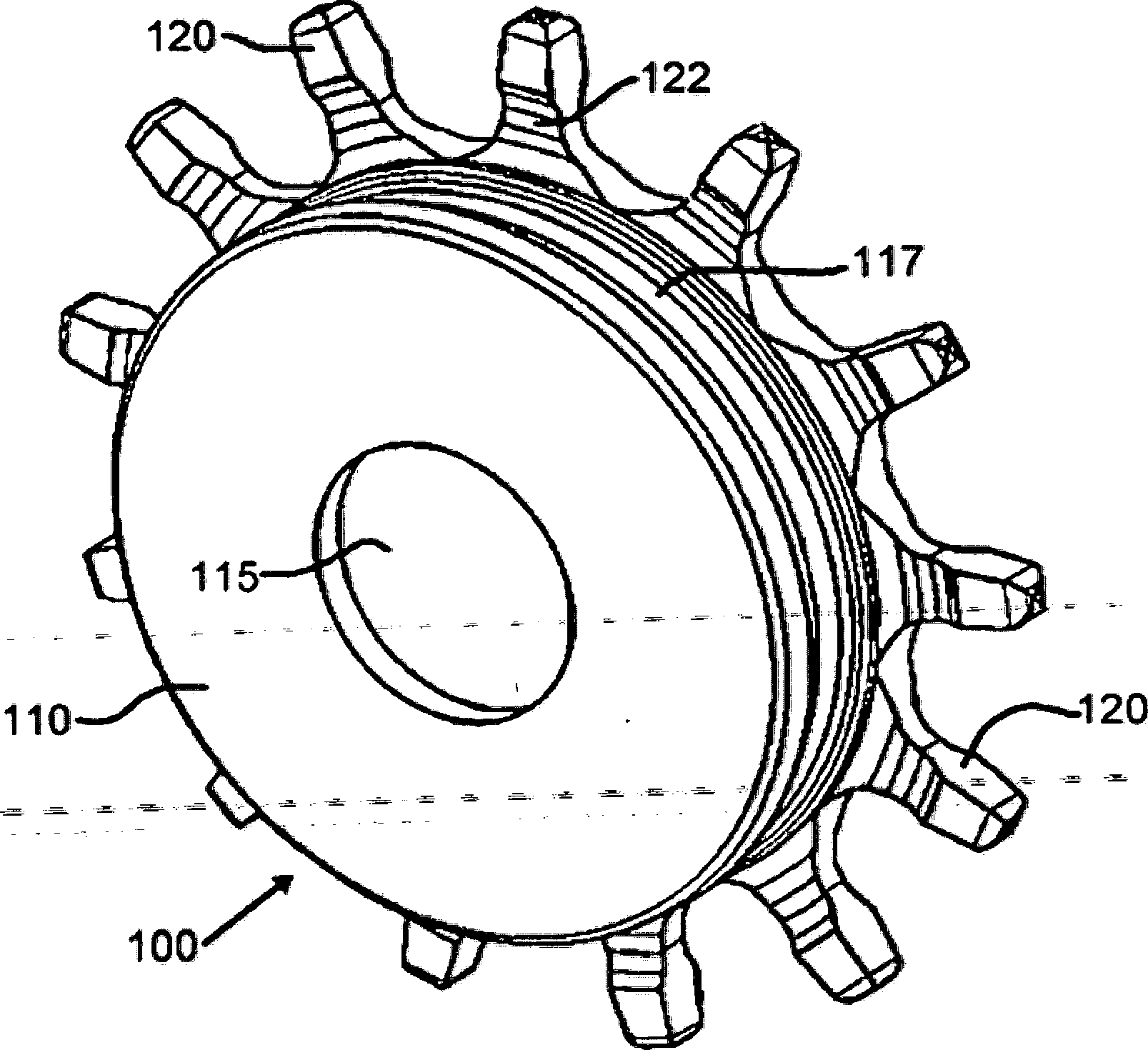
9/17 montagem do molde 100 para a utilização em um arranjo de disco de freio (não mostrado nesta figura) de acordo com a invenção. Tal como descrito abaixo, a porção de montagem 100 suporta e limita a porção de placa de freio (não mostrada nesta figura) através de diversas protuberâncias radiais 122 que são distribuídas substancialmente igualmente em torno de uma circunferência externa 117 da porção de montagem 100. A utilização das protuberâncias radiais 122, ao contrário de uma seção circunferencial contínua convencional (não mostrada), contribui significativamente à realização de desenhos de redução de massa sobre os desenhos de uma só peça convencionais.9/17 assembly of the mold 100 for use in a brake disc arrangement (not shown in this figure) according to the invention. As described below, the mounting portion 100 supports and limits the brake plate portion (not shown in this figure) through several radial protrusions 122 that are distributed substantially equally around an outer circumference 117 of the mounting portion 100. A The use of radial protrusions 122, unlike a conventional continuous circumferential section (not shown), contributes significantly to the realization of mass reduction designs over conventional one-piece designs.
[036] Conforme será descrito abaixo, as protuberâncias radiais 122 são configuradas para serem acomodadas à porção de placa de freio, e servem como o ponto da interação entre a porção de montagem e a porção de placa de freio.[036] As will be described below, the radial protrusions 122 are configured to accommodate the brake plate portion, and serve as the point of interaction between the mounting portion and the brake plate portion.
[037] Na prática da invenção, primeiramente a porção de montagem 100 é produzida, separada da porção de placa de freio. Esta seqüência de manufatura em que a porção de montagem é moldada separada da porção de placa de freio facilita se atingir a vantagem de permitir a utilização de espessuras de seção da parede significativamente mais finas, em comparação a um desenho de uma só peça convencional. Nesta realização ilustrativa específica da invenção, esta redução na espessura, em conjunto com a utilização das protuberâncias radiais 122, constitui as características primárias através da qual a redução vantajosa na massa do disco de freio (não mostrado nesta figura) é obtida.[037] In the practice of the invention, first the assembly portion 100 is produced, separate from the brake plate portion. This manufacturing sequence in which the mounting portion is molded separately from the brake plate portion makes it easier to achieve the advantage of allowing the use of significantly thinner wall section thicknesses compared to a conventional one-piece design. In this specific illustrative embodiment of the invention, this reduction in thickness, together with the use of radial protrusions 122, constitutes the primary characteristics through which the advantageous reduction in the mass of the brake disc (not shown in this figure) is achieved.
[038] A porção de montagem 100 tem uma[038] Mounting portion 100 has a
Petição 870190118475, de 14/11/2019, pág. 15/28Petition 870190118475, of 11/14/2019, p. 15/28
10/17 superfície de montagem integralmente formada 110. Nesta realização ilustrativa específica da invenção, a superfície de montagem 110 tem uma abertura 115 através da mesma que, quando da conclusão da manufatura do disco de freio, facilita sua instalação no eixo (não mostrado) de um veículo automotor (não mostrado).10/17 integrally formed mounting surface 110. In this specific illustrative embodiment of the invention, mounting surface 110 has an opening 115 through which, upon completion of the manufacture of the brake disc, facilitates its installation on the axle (not shown) of a motor vehicle (not shown).
[039] Na manufatura da porção de montagem 100 desta realização ilustrativa específica da invenção, é empregado um processo de fundição moldada à areia convencional. A porção de montagem pode ser feita de ferro cinzento, alumínio, ferro nodular ou de outros metais apropriados. No entanto, após a conclusão da fundição da porção de montagem 100, diversas etapas de processamento adicionais são requeridas na preparação para unir à porção de placa de freio.[039] In the manufacture of the assembly portion 100 of this specific illustrative embodiment of the invention, a conventional sand molded casting process is employed. The mounting portion may be made of gray iron, aluminum, nodular iron or other suitable metals. However, after the casting of the assembly portion 100 is completed, several additional processing steps are required in preparation for joining to the brake plate portion.
[040] A Figura 2(a) é uma representação da vista lateral em seção parcialmente transversal da porção de montagem 100, tal como descrito previamente com relação à Figura 1. A Figura 2(b) é uma representação em seção transversal ampliada que mostra em um detalhe maior uma protuberância radial 122 da porção de montagem 100. Além disso, a Figura 2(c) é uma representação ampliada das protuberâncias radiais 122 da porção de montagem 100. Os elementos da estrutura que foram discutidos previamente são similarmente designados.[040] Figure 2 (a) is a side view representation in partially cross section of the mounting portion 100, as previously described with respect to Figure 1. Figure 2 (b) is an enlarged cross section representation showing in greater detail a radial protuberance 122 of the mounting portion 100. In addition, Figure 2 (c) is an enlarged representation of the radial protuberances 122 of the mounting portion 100. The elements of the structure that have been discussed previously are similarly designated.
[041] Conforme mostrado nestas figuras, as protuberâncias radiais 122 se estendem radialmente para fora da circunferência externa 117. Cada uma das protuberâncias radiais 122 tem uma porção de ponta 120 formada integralmente com a mesma. Cada porção de ponta 120 tem uma superfície[041] As shown in these figures, the radial protrusions 122 extend radially outward from the outer circumference 117. Each of the radial protrusions 122 has a tip portion 120 formed integrally with it. Each tip portion 120 has a surface
Petição 870190118475, de 14/11/2019, pág. 16/28Petition 870190118475, of 11/14/2019, p. 16/28
11/17 externa 125. A fim de atingir os objetivos do desenho de aumento do amortecimento e de redução da deformação durante o serviço e a manufatura, a superfície externa 125 é produzida por um processo de usinagem convencional. Tal usinagem permite um controle maior sobre as superfícies, que é vantajoso durante o processamento adicional.11/17 external 125. In order to achieve the design objectives of increasing damping and reducing deformation during service and manufacturing, the outer surface 125 is produced by a conventional machining process. Such machining allows for greater control over surfaces, which is advantageous during further processing.
[042] Depois da usinagem tradicional, é necessário submeter a superfície externa 125 da porção de ponta 120 de diversas protuberâncias radiais 122 à usinagem com descarga elétrica (EDM). Geralmente, a finalidade principal do processo de EDM é remover o material. Um resultado secundário deste processo, no entanto, é uma mudança dentro da microestrutura de metal. Esta mudança na microestrutura provê a vantagem de aumentar extremamente as propriedades de amortecimento do metal na área submetida à EDM, um efeito secundário muito útil. Na prática da invenção, o processo de EDM é aplicado a diversas, mas não necessariamente todas, as protuberâncias radiais 122 para criar áreas com a característica de amortecimento elevado. Este amortecimento é conseguido ao dissipar modos comuns de vibração com a porção de placa de freio.[042] After traditional machining, it is necessary to subject the outer surface 125 of the tip portion 120 of various radial protuberances 122 to machining with electrical discharge (EDM). Generally, the main purpose of the EDM process is to remove the material. A secondary result of this process, however, is a change within the metal microstructure. This change in the microstructure provides the advantage of greatly increasing the damping properties of the metal in the area subjected to EDM, a very useful side effect. In the practice of the invention, the EDM process is applied to several, but not necessarily all, radial protrusions 122 to create areas with the high damping characteristic. This damping is achieved by dissipating common modes of vibration with the brake plate portion.
[043] Na prática desta realização da invenção, os resultados desejados da aplicação do processo de EDM são mais abem atingidos quando algumas, não todas as protuberâncias radiais 122 são submetidas ao processo de EDM.[043] In the practice of this embodiment of the invention, the desired results of applying the EDM process are best achieved when some, not all radial protuberances 122 are subjected to the EDM process.
É preferível que as protuberâncias radiais 122 que são processadas utilizando a EDM sejam espaçadas substancialmente igualmente em torno da circunferência da porção de montagem 100. Isto é feito de modo que haja áreas distintas distribuídas em torno da porção inteira da placa de freio comIt is preferable that the radial protrusions 122 that are processed using the EDM are spaced substantially equally around the circumference of the mounting portion 100. This is done so that there are distinct areas distributed around the entire portion of the brake plate with
Petição 870190118475, de 14/11/2019, pág. 17/28Petition 870190118475, of 11/14/2019, p. 17/28
12/17 amortecimento muito elevado, disponíveis para impedir que a vibração aumente e se propague em torno da porção de placa de freio.12/17 very high damping, available to prevent vibration from increasing and spreading around the brake plate portion.
[044] Depois do processo de EDM, um revestimento de cerâmica (não mostrado) é aplicado a todas as protuberâncias radiais 122. O revestimento de cerâmica é de uma espessura que impossibilita a soldagem entre as porções de ponta das protuberâncias radiais e a porção de placa de freio. Durante a formação da porção de placa de freio, como será discutido abaixo, o metal derretido será despejado em torno das protuberâncias radiais 122 da porção de montagem 100. Se a porção de placa de freio e a porção de montagem 100 forem soldadas juntas durante esta etapa, os benefícios conseguidos pela presente invenção serão em grande parte perdidos porque a porção de montagem e a porção de placa de freio não poderão se comportar como dois corpos separados. Quando da conclusão da aplicação do revestimento de cerâmica, a porção de montagem 100 está pronta para ser combinada com a porção de placa de freio, como segue.[044] After the EDM process, a ceramic coating (not shown) is applied to all radial protuberances 122. The ceramic coating is of a thickness that makes it impossible to weld between the tip portions of the radial protuberances and the brake plate. During the formation of the brake plate portion, as will be discussed below, the molten metal will be poured around the radial protuberances 122 of the mounting portion 100. If the brake plate portion and the mounting portion 100 are welded together during this step, the benefits achieved by the present invention will be largely lost because the mounting portion and the brake plate portion cannot behave as two separate bodies. Upon completion of the ceramic coating application, the mounting portion 100 is ready to be combined with the brake plate portion, as follows.
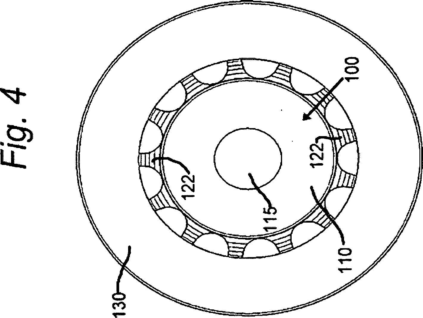
[045] A Figura 3 é uma representação em perspectiva esquemática simplificada de um disco de freio de molde (não especificamente designado) que mostra a porção de montagem do molde 100 com uma porção da placa de freio do molde 130. A Figura 4 é uma representação em planta do disco de freio de molde da Figura 3. Os elementos da estrutura que foram discutidos previamente são similarmente designados. A porção de placa de freio de um disco de freio também é conhecida no estado da técnica como uma faixa de freio.[045] Figure 3 is a simplified schematic perspective representation of a mold brake disc (not specifically designated) showing the mold mounting portion 100 with a portion of the mold brake plate 130. Figure 4 is a plan representation of the mold brake disc in Figure 3. The elements of the structure that were discussed previously are similarly designated. The brake plate portion of a brake disc is also known in the art as a brake strip.
[046] Pode-se observar nestas figuras que a porção da placa de freio 130 é instalada para circundar[046] It can be seen in these figures that the brake plate portion 130 is installed to surround
Petição 870190118475, de 14/11/2019, pág. 18/28Petition 870190118475, of 11/14/2019, p. 18/28
13/17 circunferencialmente a montagem da porção 100. Embora as porções das protuberâncias radiais 122 sejam visíveis nestas figuras, as porções de ponta 120 são contidas dentro da circunferência interna da porção da placa de freio 130 e, portanto, não podem ser vistas nestas figuras.13/17 circumferentially the assembly of the portion 100. Although the portions of the radial protrusions 122 are visible in these figures, the tip portions 120 are contained within the inner circumference of the brake plate portion 130 and therefore cannot be seen in these figures .
[047] A Figura 5(a) é uma representação em seção parcialmente transversal do disco de freio de molde das Figuras 3 e 4. A Figura 5(b) é uma representação em seção parcialmente transversal ampliada da interconexão entre a porção de montagem moldada 100 e a porção da placa de freio do molde 130. Os elementos da estrutura que foram discutidos previamente são similarmente designados.[047] Figure 5 (a) is a partially cross-sectional representation of the mold brake disk of Figures 3 and 4. Figure 5 (b) is an enlarged partially cross-sectional representation of the interconnection between the molded mounting portion. 100 and the brake plate portion of the mold 130. The elements of the structure which have been discussed previously are similarly designated.
[048] Pode-se observar nas Figuras 5(a) e 5(b) que as porções de ponta 120 das protuberâncias radiais 122 são cercadas dentro da circunferência interna (não especificamente designada) da porção da placa de freio 130. A combinação da porção de montagem 100 e da porção da placa de freio 130 é realmente a adição de uma porção à outra. Mais especificamente, a porção da placa de freio 130 é, nesta realização da invenção, fundida em torno das protuberâncias radiais 122 da porção de montagem 100. No entanto, é essencial que a porção de montagem 100 seja mantida na orientação correta e precisa enquanto o metal para a porção da placa de freio de molde 130 está sendo despejado e esfriado. Na prática de uma realização ilustrativa específica da invenção, este problema é resolvido utilizando um núcleo de areia.[048] It can be seen in Figures 5 (a) and 5 (b) that the tip portions 120 of the radial protrusions 122 are surrounded within the inner circumference (not specifically designated) of the brake plate portion 130. The combination of the mounting portion 100 and brake plate portion 130 is actually the addition of one portion to another. More specifically, the brake plate portion 130 is, in this embodiment of the invention, fused around the radial protrusions 122 of the mounting portion 100. However, it is essential that the mounting portion 100 is maintained in the correct and precise orientation while the metal for the mold brake plate portion 130 is being poured and cooled. In the practice of a specific illustrative embodiment of the invention, this problem is solved using a sand core.
[049] A Figura 6(a) é uma representação em planta do interior do disco de freio de molde da Figura 3 durante a manufatura, que mostra um núcleo de areia 140. A[049] Figure 6 (a) is a plan view of the interior of the mold brake disk of Figure 3 during manufacture, showing a sand core 140. The
Petição 870190118475, de 14/11/2019, pág. 19/28Petition 870190118475, of 11/14/2019, p. 19/28
14/1714/17
Figura 6(b) é uma ampliação de uma porção designada da representação em planta da Figura 6(a), e mostra um detalhe maior da interconexão entre a porção de montagem 100 e o núcleo de areia 140 antes da fundição da porção da faixa de freio (não mostrada nesta figura).Figure 6 (b) is an enlargement of a designated portion of the plan representation of Figure 6 (a), and shows a greater detail of the interconnection between the mounting portion 100 and the sand core 140 before the casting of the strip portion. brake (not shown in this figure).
[050] Em um desenho de uma peça só convencional de um disco de freio, a porção de placa de freio é formada utilizando uma combinação de dois moldes de areia (não mostrados) com um núcleo de areia, tal como o núcleo de areia 140 prensado no meio. O núcleo de areia permite a produção de uma geometria detalhada, e é mantido no lugar pelos dois moldes de areia em um ou outro lado do núcleo de areia.[050] In a conventional one-piece design of a brake disc, the brake plate portion is formed using a combination of two sand molds (not shown) with a sand core, such as the sand core 140 pressed in the middle. The sand core allows for the production of a detailed geometry, and is held in place by the two sand molds on either side of the sand core.
[051] Na prática desta realização da invenção, a porção de montagem 100 é combinada com o núcleo de areia 140 para garantir que a orientação apropriada seja mantida durante todo o processo de fundição da porção de placa de freio. Nesta realização, o núcleo de areia 140 é produzido ao soprar a areia (não especificamente designada) em um molde, chamado tipicamente de caixa de núcleo. Ao inserir a porção de montagem 100 na caixa de núcleo, e então soprar a areia em torno da mesma para produzir o núcleo de areia, o resultado é um artigo de combinação do núcleo de areia/da porção de montagem.[051] In practicing this embodiment of the invention, the mounting portion 100 is combined with the sand core 140 to ensure that the proper orientation is maintained throughout the casting process of the brake plate portion. In this embodiment, the sand core 140 is produced by blowing the sand (not specifically designated) into a mold, typically called the core box. When inserting the mounting portion 100 into the core box, and then blowing the sand around it to produce the sand core, the result is a combination article of the sand core / mounting portion.
[052] O artigo de combinação do núcleo de areia/da porção de montagem é então introduzido entre as duas seções de molde de areia como se fosse um núcleo de areia típico. Os moldes de areia mantêm o artigo de combinação do núcleo de areia/da porção de montagem em alinhamento apropriado, garantindo que a porção de placa de freio do molde se solidifique corretamente em torno das protuberâncias[052] The sand core / assembly portion combination article is then inserted between the two sand mold sections as if it were a typical sand core. Sand molds keep the sand core / assembly portion combination article in proper alignment, ensuring that the brake plate portion of the mold properly solidifies around the protrusions
Petição 870190118475, de 14/11/2019, pág. 20/28Petition 870190118475, of 11/14/2019, p. 20/28
15/17 radiais 122 da porção de montagem 100. Uma vez que o revestimento de cerâmica impossibilita a soldagem entre a porção de placa de freio e a porção de montagem durante a fundição da porção de placa de freio, é produzido desse modo um sistema de duas porções que são limitadas juntas, mas que reagem independentemente ao estímulo. Por causa da relação independente, a deflexão/deformação da porção de placa de freio durante a usinagem e a aplicação como um freio de veículo será extremamente reduzida.Radial 15/17 122 of the mounting portion 100. Since the ceramic coating makes welding between the brake plate portion and the mounting portion impossible during casting of the brake plate portion, a two portions that are bound together, but that independently react to the stimulus. Because of the independent relationship, the deflection / deformation of the brake plate portion during machining and application as a vehicle brake will be greatly reduced.
[053] Pode-se observar ainda nas Figuras 6(a) e 6(b) que o núcleo de areia 140 tem aberturas através do mesmo. Sob este aspecto, vide as aberturas 142, 144, e 146 na Figura 6(b). Como será visto com relação à Figura 7 abaixo, estas aberturas permitem as criações de colunas entre as duas metades da porção da placa de freio 130. Mais especificamente, parte do metal derretido (não mostrada) que é despejada durante o processo de fundição da porção da placa de freio 130 é acomodada dentro das aberturas para a formação das colunas.[053] It can also be seen in Figures 6 (a) and 6 (b) that the sand core 140 has openings through it. In this regard, see openings 142, 144, and 146 in Figure 6 (b). As will be seen in relation to Figure 7 below, these openings allow the creation of columns between the two halves of the brake plate portion 130. More specifically, part of the molten metal (not shown) that is poured out during the casting process of the portion of the brake plate 130 is accommodated inside the openings for the formation of the columns.
[054] A Figura 7 é uma representação em perspectiva esquemática simplificada de um disco de freio de molde que mostra a porção de montagem 100 combinada com a porção da placa de freio 130, e que mostra adicionalmente as aberturas de montagem 160 através das mesmas para permitir a montagem do disco de freio no eixo de um veículo automotor (não mostrado). Os elementos da estrutura que foram discutidos previamente são similarmente designados.[054] Figure 7 is a simplified schematic perspective representation of a mold brake disc showing the mounting portion 100 combined with the brake plate portion 130, and showing additionally the mounting openings 160 through them for allow the mounting of the brake disc on the axle of a motor vehicle (not shown). The elements of the structure that were discussed previously are similarly designated.
[055] Pode-se observar nesta figura que são providas colunas, tais como as colunas 152, 154, e 156 interpostas entre as duas metades da porção de placa de[055] It can be seen in this figure that columns are provided, such as columns 152, 154, and 156 interposed between the two halves of the plate portion
Petição 870190118475, de 14/11/2019, pág. 21/28Petition 870190118475, of 11/14/2019, p. 21/28
16/17 freio. Nesta realização ilustrativa específica da invenção, a coluna 152 é o resultado do metal derretido que entra na abertura 142 (Figuras 6(a) e 6(b)); a coluna 154 é formada em conseqüência da presença da abertura 144; e a coluna 156 é o resultado da abertura 146. Deve ficar compreendido que as aberturas no núcleo de areia 140 e as colunas resultantes na porção da placa de freio 130 são replicadas sobre a circunferência da porção da placa de freio 130. Além disso, as aberturas e as colunas resultantes não são limitadas à configuração mostrada nas presentes figuras. Os elementos versados na técnica podem produzir aberturas adicionais e diferentes e configurações correspondentes da coluna sem que se desviem da invenção reivindicada.16/17 brake. In this specific illustrative embodiment of the invention, column 152 is the result of the molten metal entering the opening 142 (Figures 6 (a) and 6 (b)); column 154 is formed as a result of the presence of aperture 144; and column 156 is the result of opening 146. It should be understood that the openings in the sand core 140 and the resulting columns in the brake plate portion 130 are replicated over the circumference of the brake plate portion 130. In addition, the openings and the resulting columns are not limited to the configuration shown in the present figures. The elements skilled in the art can produce additional and different openings and corresponding column configurations without deviating from the claimed invention.
[056] Após a fundição da porção de placa de freio em torno da porção de montagem, resta o processo de usinagem final da peça do disco de freio completa. Na prática desta realização ilustrativa específica da invenção, a usinagem é efetuada da mesma maneira que um desenho de uma peça só convencional. No entanto, a presente invenção provê menos deformação, o que resulta no controle do processo aumentado, e aumenta significativamente a probabilidade de que especificações geométricas e dimensionais de usinagem com tolerância inferior sejam conseguidas.[056] After casting the brake plate portion around the assembly portion, the final machining process of the complete brake disc part remains. In the practice of this specific illustrative embodiment of the invention, machining is carried out in the same way as a conventional one-piece design. However, the present invention provides less deformation, which results in increased process control, and significantly increases the likelihood that geometric and dimensional machining specifications with lower tolerance are achieved.
[057] A Figura 8 é uma representação lateral em seção parcialmente transversal do disco de freio de molde acabado da Figura 7. Os elementos da estrutura que foram discutidos previamente são similarmente designados. A Figura 8 mostra o disco de freio de molde após a usinagem.[057] Figure 8 is a side representation in partially cross-section of the finished mold brake disc in Figure 7. The elements of the structure that were discussed previously are similarly designated. Figure 8 shows the mold brake disc after machining.
[058] Embora a invenção tenha sido descrita em termos das realizações e aplicações específicas, os elementos[058] Although the invention has been described in terms of specific achievements and applications, the elements
Petição 870190118475, de 14/11/2019, pág. 22/28Petition 870190118475, of 11/14/2019, p. 22/28
17/17 versados na técnica podem, à luz deste ensinamento, gerar realizações adicionais sem exceder o âmbito, ou sem se desviar do caráter da invenção reivindicada.17/17 skilled in the art can, in the light of this teaching, generate additional achievements without exceeding the scope, or without deviating from the character of the claimed invention.
Conseqüentemente, deve ficar compreendido que o desenho e a descrição neste pedido de patente são apresentados para facilitar a compreensão da invenção, e não devem ser interpretados como limitadores do âmbito da mesma.Consequently, it should be understood that the design and description in this patent application are presented to facilitate the understanding of the invention, and should not be interpreted as limiting the scope of the invention.
Petição 870190118475, de 14/11/2019, pág. 23/28Petition 870190118475, of 11/14/2019, p. 23/28
1/21/2
Claims (4)


Applications Claiming Priority (2)
| Application Number | Priority Date | Filing Date | Title |
|---|---|---|---|
| US12727208P | 2008-05-08 | 2008-05-08 | |
| PCT/US2009/002880 WO2009137101A2 (en) | 2008-05-08 | 2009-05-08 | Composite brake disc |
Publications (2)
| Publication Number | Publication Date |
|---|---|
| BRPI0908310A2 BRPI0908310A2 (en) | 2015-08-18 |
| BRPI0908310B1 true BRPI0908310B1 (en) | 2020-04-22 |
Family
ID=41265232
Family Applications (1)
| Application Number | Title | Priority Date | Filing Date |
|---|---|---|---|
| BRPI0908310A BRPI0908310B1 (en) | 2008-05-08 | 2009-05-08 | brake disc arrangement |
Country Status (6)
| Country | Link |
|---|---|
| US (1) | US8939266B2 (en) |
| EP (1) | EP2286106B1 (en) |
| CN (1) | CN102239344B (en) |
| BR (1) | BRPI0908310B1 (en) |
| MX (1) | MX2010012118A (en) |
| WO (1) | WO2009137101A2 (en) |
Families Citing this family (27)
| Publication number | Priority date | Publication date | Assignee | Title |
|---|---|---|---|---|
| BRPI0908310B1 (en) | 2008-05-08 | 2020-04-22 | Rassini Frenos Sa De Cv | brake disc arrangement |
| EP2359021B1 (en) * | 2008-12-08 | 2014-10-22 | Sheet Cast Technologies GmbH | Brake disc |
| IT1395120B1 (en) * | 2009-07-29 | 2012-09-05 | Freni Brembo Spa | BRAKING RANGE AND DISC BRAKE DISC |
| IT1403905B1 (en) * | 2011-01-26 | 2013-11-08 | Freni Brembo Spa | DISC FOR DISC BRAKES |
| KR101294165B1 (en) * | 2011-08-10 | 2013-08-08 | 현대자동차주식회사 | Brake disc using different materials and method for producing the same |
| MX359060B (en) * | 2011-09-19 | 2018-09-13 | Rassini Frenos Sa De Cv | Composite rotor. |
| KR101355613B1 (en) * | 2012-08-13 | 2014-01-27 | 현대자동차주식회사 | Brake disc |
| CN106499757A (en) * | 2015-09-06 | 2017-03-15 | 房殊 | The ceramic skeleton of two-dimensional structure periodic arrangement strengthens light metal composite brake disk |
| CN106499756A (en) * | 2015-09-06 | 2017-03-15 | 房殊 | The disorderly arranged ceramic skeleton of two-dimensional structure strengthens light metal composite brake disk |
| US10267370B2 (en) | 2016-02-09 | 2019-04-23 | Saf-Holland, Inc. | Disc brake rotor adapter |
| US10100888B2 (en) * | 2016-05-16 | 2018-10-16 | Shimano Inc. | Bicycle disc brake rotor |
| KR101866058B1 (en) | 2016-09-22 | 2018-06-11 | 현대자동차주식회사 | Solid type brake disc and manufacturing method of the same |
| DE102017208288A1 (en) * | 2016-09-29 | 2018-03-29 | Continental Teves Ag & Co. Ohg | Brake disc pot and brake disc with improved vehicle interface |
| KR102042255B1 (en) * | 2016-11-22 | 2019-11-11 | 현대자동차(주) | Solid type brake disc and manufacturing method of the same |
| US10612612B2 (en) | 2016-11-22 | 2020-04-07 | Hyundai Motor Company | Solid type brake disc and manufacturing method of the same |
| KR102324761B1 (en) * | 2017-05-23 | 2021-11-10 | 현대자동차주식회사 | Manufacturing method for brake disc using different materials and brake disc using different materials manufactured by using the same |
| CN107598089A (en) * | 2017-09-28 | 2018-01-19 | 山东金麒麟股份有限公司 | A kind of brake disc stack mold and brake disc casting method |
| CN108253046B (en) * | 2018-03-27 | 2023-08-04 | 烟台胜地汽车零部件制造有限公司 | Lightweight composite brake disc and processing method thereof |
| CN108331864A (en) * | 2018-04-19 | 2018-07-27 | 驻马店恒久机械制造有限公司 | A kind of composite brake disc and preparation method thereof |
| US11118643B2 (en) * | 2018-12-12 | 2021-09-14 | Hyundai Motor Company | Brake disc |
| DE102019135337B4 (en) * | 2018-12-28 | 2023-06-22 | Honda Motor Co., Ltd. | ALIMINIUM-CERAMIC COMPOSITE BRAKE ASSEMBLY |
| CN109570441A (en) * | 2019-01-31 | 2019-04-05 | 刘娜 | A kind of Braking System for Multiple Units brake plate support casting technique of 230km/h |
| CN110081103A (en) * | 2019-05-24 | 2019-08-02 | 驻马店恒久机械制造有限公司 | A kind of bimetallic general brake disk and preparation method thereof |
| US20210039434A1 (en) * | 2019-08-06 | 2021-02-11 | Consolidated Metco, Inc. | Wheel Hub with Integrated Circular Brake Element |
| IT201900025222A1 (en) | 2019-12-23 | 2021-06-23 | Freni Brembo Spa | Disc brake disc, disc brake and production method |
| FR3116577B1 (en) * | 2020-11-26 | 2024-02-16 | Psa Automobiles Sa | BRAKING DEVICE COMPRISING A BI-MATERIAL DISC AND VEHICLE COMPRISING SUCH A BRAKING DEVICE |
| CN112658217A (en) * | 2021-03-18 | 2021-04-16 | 龙口市和义机械配件有限公司 | Manufacturing method of ventilation brake disc |
Family Cites Families (22)
| Publication number | Priority date | Publication date | Assignee | Title |
|---|---|---|---|---|
| GB1323832A (en) * | 1970-07-03 | 1973-07-18 | Daimler Benz Ag | Disc elements for disc brakes |
| US5184663A (en) * | 1988-06-14 | 1993-02-09 | Aisin Takaoka Co., Ltd. | Ventilated disk and process for making same |
| DE3920418A1 (en) * | 1989-06-22 | 1991-01-03 | Schwaebische Huettenwerke Gmbh | BRAKE DISC FOR DISC BRAKES |
| US5106010A (en) * | 1990-09-28 | 1992-04-21 | Chromalloy Gas Turbine Corporation | Welding high-strength nickel base superalloys |
| US5862892A (en) * | 1996-04-16 | 1999-01-26 | Hayes Lemmerz International Inc. | Composite rotor for caliper disc brakes |
| US6164423A (en) * | 1997-05-02 | 2000-12-26 | Hayes Lemmerz International, Inc. | Vented rotor for caliper disc brakes and the like |
| DE19719634C1 (en) * | 1997-05-09 | 1999-03-04 | Daimler Benz Ag | Brake unit with a ceramic brake disk bolted to a hub |
| US6131707A (en) * | 1997-06-04 | 2000-10-17 | Kelsey-Hayes Company | Disc brake rotor and method for producing same |
| DE19929390B4 (en) * | 1999-06-28 | 2004-05-06 | Otto Sauer Achsenfabrik Keilberg | Brake disc arrangement |
| US6505716B1 (en) * | 1999-11-05 | 2003-01-14 | Hayes Lemmerz International, Inc. | Damped disc brake rotor |
| US20010040075A1 (en) * | 1999-12-30 | 2001-11-15 | Daudi Anwar R. | Method of increasing the length and thickness of graphite flakes in a gray iron brake rotor |
| EP1128083B1 (en) * | 2000-02-23 | 2004-09-15 | Bayerische Motoren Werke Aktiengesellschaft | Method for manufacturing a brake disc |
| EP1263544A1 (en) | 2000-03-09 | 2002-12-11 | Hayes Lemmerz International, Inc. | Apparatus and method of machining brake components |
| JP2002097080A (en) * | 2000-09-21 | 2002-04-02 | Mazda Motor Corp | Method of manufacturing preform for compositing |
| WO2002097292A1 (en) * | 2001-05-28 | 2002-12-05 | Freni Brembo S.P.A. | A braking band for a brake disk |
| ES2223890T3 (en) * | 2001-06-28 | 2005-03-01 | Freni Brembo S.P.A. | COMPOUND DISC FOR A DISC BRAKE. |
| US7937819B2 (en) * | 2005-09-19 | 2011-05-10 | GM Global Technology Operations LLC | Method of manufacturing a friction damped disc brake rotor |
| US20070246314A1 (en) * | 2004-10-26 | 2007-10-25 | Freni Brembo S.P.A. | Disc for a Disc Brake |
| US20070199778A1 (en) * | 2006-02-27 | 2007-08-30 | Lee Kwangjin M | Vented disc brake rotor |
| US8210232B2 (en) * | 2007-09-20 | 2012-07-03 | GM Global Technology Operations LLC | Lightweight brake rotor and components with composite materials |
| BRPI0908310B1 (en) | 2008-05-08 | 2020-04-22 | Rassini Frenos Sa De Cv | brake disc arrangement |
| US20110290602A1 (en) * | 2010-05-28 | 2011-12-01 | Gm Global Technology Operations, Inc. | Interconnection for cast-in-place components |
-
2009
- 2009-05-08 BR BRPI0908310A patent/BRPI0908310B1/en not_active IP Right Cessation
- 2009-05-08 CN CN200980122560.1A patent/CN102239344B/en not_active Expired - Fee Related
- 2009-05-08 EP EP09743088.8A patent/EP2286106B1/en not_active Not-in-force
- 2009-05-08 WO PCT/US2009/002880 patent/WO2009137101A2/en active Application Filing
- 2009-05-08 US US12/736,763 patent/US8939266B2/en not_active Expired - Fee Related
- 2009-05-08 MX MX2010012118A patent/MX2010012118A/en active IP Right Grant
Also Published As
| Publication number | Publication date |
|---|---|
| MX2010012118A (en) | 2011-07-20 |
| EP2286106A2 (en) | 2011-02-23 |
| US8939266B2 (en) | 2015-01-27 |
| US20110061980A1 (en) | 2011-03-17 |
| EP2286106A4 (en) | 2015-03-04 |
| BRPI0908310A2 (en) | 2015-08-18 |
| EP2286106B1 (en) | 2017-09-27 |
| CN102239344B (en) | 2014-11-12 |
| WO2009137101A3 (en) | 2010-01-07 |
| CN102239344A (en) | 2011-11-09 |
| WO2009137101A2 (en) | 2009-11-12 |
Similar Documents
| Publication | Publication Date | Title |
|---|---|---|
| BRPI0908310B1 (en) | brake disc arrangement | |
| US20070235270A1 (en) | Insert for manufacture of an enhanced sound dampening composite rotor casting and method thereof | |
| US4093018A (en) | Casting methods with composite molded core assembly | |
| US20060254741A1 (en) | Manufacturing method for a wax pattern for making a golf club head | |
| US6298899B1 (en) | Water jacket core | |
| US9488238B2 (en) | Composite rotor | |
| CN105408124B (en) | Vehicle wheel obtained from a thermoplastic polymer | |
| JP2009515708A5 (en) | ||
| JP2009161166A (en) | Movement prevention collar of casting metal for stabilizer and manufacturing method | |
| JP2008514863A (en) | Exhaust manifold with double walls | |
| JP4718872B2 (en) | Motorcycle wheel casting mold and casting method | |
| JP2005517136A (en) | Casting brake disc | |
| JP2016155159A (en) | Precision casting method and dewaxing auxiliary member | |
| KR100411077B1 (en) | Casting method of aluminum cylinder block | |
| JPH04200966A (en) | Die structure of wheel for vehicle | |
| KR101766079B1 (en) | Manufacturing method of brake disc | |
| JPH10146666A (en) | Method for cooling die | |
| JP2005052876A (en) | Method for producing vehicle wheel | |
| IT201900017240A1 (en) | DISC FOR DISC BRAKE FOR MOTORCYCLES | |
| BR102016021817A2 (en) | method for thermal control of on-site cast components during fabrication | |
| JPS6242701B2 (en) | ||
| JPS6268668A (en) | Manufacture of exhaust manifold | |
| JPS6358295B2 (en) | ||
| KR101989602B1 (en) | apparatus for molding a wheel for vehicle | |
| JPH07266340A (en) | Resin molds |
Legal Events
| Date | Code | Title | Description |
|---|---|---|---|
| B06F | Objections, documents and/or translations needed after an examination request according [chapter 6.6 patent gazette] | ||
| B06U | Preliminary requirement: requests with searches performed by other patent offices: procedure suspended [chapter 6.21 patent gazette] | ||
| B09A | Decision: intention to grant [chapter 9.1 patent gazette] | ||
| B16A | Patent or certificate of addition of invention granted [chapter 16.1 patent gazette] |
Free format text: PRAZO DE VALIDADE: 10 (DEZ) ANOS CONTADOS A PARTIR DE 22/04/2020, OBSERVADAS AS CONDICOES LEGAIS. |
|
| B21F | Lapse acc. art. 78, item iv - on non-payment of the annual fees in time |
Free format text: REFERENTE A 13A ANUIDADE. |
|
| B24J | Lapse because of non-payment of annual fees (definitively: art 78 iv lpi, resolution 113/2013 art. 12) |
Free format text: EM VIRTUDE DA EXTINCAO PUBLICADA NA RPI 2669 DE 03-03-2022 E CONSIDERANDO AUSENCIA DE MANIFESTACAO DENTRO DOS PRAZOS LEGAIS, INFORMO QUE CABE SER MANTIDA A EXTINCAO DA PATENTE E SEUS CERTIFICADOS, CONFORME O DISPOSTO NO ARTIGO 12, DA RESOLUCAO 113/2013. |