BRPI0901546B1 - air-cooled engine - Google Patents
air-cooled engine Download PDFInfo
- Publication number
- BRPI0901546B1 BRPI0901546B1 BRPI0901546-9A BRPI0901546A BRPI0901546B1 BR PI0901546 B1 BRPI0901546 B1 BR PI0901546B1 BR PI0901546 A BRPI0901546 A BR PI0901546A BR PI0901546 B1 BRPI0901546 B1 BR PI0901546B1
- Authority
- BR
- Brazil
- Prior art keywords
- cylinder head
- engine
- air
- temperature sensor
- oil temperature
- Prior art date
Links
Images
Abstract
MOTOR REFRIGERADO A AR. A presente invenção refere-se a um motor refrigerado a ar que inclui um motor, provido com um cárter, um cilindro para armazenar um pistão deslizante no interior, e uma cabeça de cilindro possuindo um orifício de admissão comunicando-se com uma passagem de admissão e uma câmara de combustão formada no interior, um acessório de motor incluindo uma bomba de combustível disposta em um lado da passagem de admissão, um mecanismo acionador de válvula reguladora,e, uma unidade de controle de corpo da válvula reguladora; e um detector suportado em uma superfície da parede na qual uma abertura do orifício de admissão da cabeça do cilindro é formada e, disposta em um mesmo lado que o acessório de motor com relação à passagem de admissão como uma vista planar, para detectar um estado da câmara de combustão, em que na cabeça do cilindro com o detector para detectar o estado da câmara de combustão no caso onde o detector se projeta a partir da cabeça do cilindro a montante da fonte do fluxo da passagem de admissão, a porção saliente é reduzida para permitir que o acessório do motor fique próximo do bloco do cilindro.(...)AIR-COOLED ENGINE. The present invention relates to an air-cooled engine that includes an engine, provided with a crankcase, a cylinder for storing a sliding piston inside, and a cylinder head having an inlet port communicating with an inlet passage. and a combustion chamber formed inside, an engine accessory including a fuel pump arranged on one side of the intake port, a regulating valve actuating mechanism, and a regulating valve body control unit; and a detector supported on a wall surface in which an opening of the cylinder head intake port is formed and, arranged on the same side as the engine accessory with respect to the intake passage as a planar view, to detect a state of the combustion chamber, where in the cylinder head with the detector to detect the state of the combustion chamber in the case where the detector projects from the cylinder head upstream of the source of the flow of the intake passage, the projecting portion is reduced to allow the engine accessory to be close to the cylinder block. (...)
Description
[001] A presente invenção refere-se a um motor refrigerado a ar equipado com um detector para detectar um estado de uma câmara de combustão ou um sensor de temperatura do óleo para medir uma temperatura do óleo para lubrificar o mecanismo de válvula.[001] The present invention relates to an air-cooled engine equipped with a detector to detect a state of a combustion chamber or an oil temperature sensor to measure an oil temperature to lubricate the valve mechanism.
[002] A estrutura tendo o sensor de temperatura do óleo para de tectar a temperatura do óleo disposta na direção longitudinal do corpo do veículo enquanto sendo suportada no lado do orifício de admissão da cabeça do cilindro tem sido descrita (vide Documento de Patente 1). Na técnica relacionada, o sensor de temperatura do óleo projeta-se largamente do cilindro, e, consequentemente, o acessório de motor fica posicionado distante do cilindro para o propósito de evitar a interferência com o sensor de temperatura do óleo, resultando em layout dificultado em torno do motor.[002] The structure having the oil temperature sensor stops to detect the oil temperature arranged in the longitudinal direction of the vehicle body while being supported on the side of the cylinder head intake port has been described (see Patent Document 1) . In the related technique, the oil temperature sensor protrudes widely from the cylinder, and, consequently, the engine accessory is positioned away from the cylinder for the purpose of avoiding interference with the oil temperature sensor, resulting in a difficult layout in around the engine.
[003] Documento de Patente 1 JP-A N° 2007-175249[003] Patent Document 1 JP-A No. 2007-175249
[004] É um objetivo da presente invenção prover um motor refri gerado a ar capaz de reduzir a distância entre o acessório do motor e o bloco de cilindro/cabeça do cilindro pelo decréscimo da quantidade de protrusão do detector para detectar o estado de câmara de combustão no sentido a montante da passagem de admissão a partir da cabeça do cilindro.[004] It is an objective of the present invention to provide an air-cooled engine capable of reducing the distance between the engine accessory and the cylinder block / cylinder head by decreasing the amount of protrusion of the detector to detect the state of the chamber. combustion in the direction upstream of the intake passage from the cylinder head.
[005] A presente invenção tem sido realizada para solucionar o problema acima mencionado. A presente invenção de acordo com a reivindicação 1 provê um motor refrigerado a ar que inclui um motor provido com um cárter, um cilindro para armazenar um pistão deslizante dentro, e, uma cabeça do cilindro tendo um orifício de admissão comunicado com uma passagem de admissão e uma câmara de combustão formada dentro, um acessório de motor incluindo uma bomba de combustível disposta em um lado da passagem de admissão, um mecanismo acionador de válvula reguladora e uma unidade de controle de corpo da válvula reguladora, e, um detector suportado em uma superfície da parede em que uma abertura do orifício de admissão da cabeça do cilindro é formada, e, disposto em um mesmo lado que o acessório de motor com relação à passagem de admissão como uma vista planar para detectar um estado da câmara de combustão. O detector inclui um eixo que intersecta uma parede externa da cabeça do cilindro. Uma extremidade externa do eixo do detector é inclinada para um centro de um corpo do veículo.[005] The present invention has been carried out to solve the aforementioned problem. The present invention according to claim 1 provides an air-cooled engine that includes an engine provided with a crankcase, a cylinder for storing a sliding piston inside, and a cylinder head having an inlet port communicated with an inlet passage. and a combustion chamber formed inside, an engine accessory including a fuel pump arranged on one side of the intake passage, a regulating valve actuation mechanism and a regulating valve body control unit, and, a detector supported on a surface of the wall on which an opening of the cylinder head intake orifice is formed, and arranged on the same side as the engine accessory with respect to the intake passage as a planar view to detect a state of the combustion chamber. The detector includes an axis that intersects an external wall of the cylinder head. An outer end of the detector's axis is tilted to a center of a vehicle body.
[006] No motor refrigerado a ar da reivindicação 2 de acordo com a reivindicação 1, a parede externa da cabeça do cilindro inclui aletas refrigeradas a ar que se projetam verticalmente e um suspensor de motor tendo uma parte das aletas refrigeradas a ar abaixo do suspensor de motor descontinuamente formada para definir uma porção ausente de aleta. O detector é um sensor de temperatura do óleo para medição de uma temperatura do óleo, e, disposto na porção ausente de aleta.[006] In the air-cooled engine of
[007] No motor refrigerado a ar da reivindicação 3, de acordo com a reivindicação 2, uma superfície do fundo de um reservatório de óleo é separada de uma porção de detecção em uma extremidade dianteira do sensor de temperatura do óleo por uma predeterminada distância para medição de uma temperatura do óleo dentro da câmara de combustão.[007] In the air-cooled engine of claim 3, according to
[008] No motor refrigerado a ar da reivindicação 4, de acordo com as reivindicações 2 e 3, a abertura do orifício de admissão é for mada em uma superfície traseira do cilindro que é inclinada para frente e o sensor de temperatura do óleo é disposto na superfície traseira do cilindro. Uma aleta da posição mais baixa das aletas refrigeradas a ar fica disposta abaixo da porção ausente de aleta e um furo de drenagem é formado na aleta da posição mais baixa.[008] In the air-cooled engine of
[009] No motor refrigerado a ar da reivindicação 5, de acordo com as reivindicações 1 a 4, na cabeça do cilindro, uma superfície aberta do orifício de admissão fica paralela com uma superfície da sede de montagem do detector.[009] In the air-cooled engine of
[0010] Na invenção de acordo com a reivindicação 1, como o de tector é disposto adjacente ao orifício de admissão e a passagem de admissão a temperaturas normais, distante do lado de exaustão, o detector não é influenciado pelo calor. Como a extremidade externa do detector é inclinada para ser direcionada para o centro do corpo do veículo, a quantidade de protrusão da cabeça do cilindro ao lado a montante da passagem de admissão é reduzida de modo a trazer o acessório de motor para estar mais próximo do bloco de cilindro e da cabeça do cilindro. O eixo do detector intersecta a parede externa da cabeça do cilindro. Todavia, é indiferente se o eixo penetra ou não na parede externa da cabeça do cilindro.[0010] In the invention according to claim 1, as the tector is disposed adjacent to the inlet orifice and the inlet passage at normal temperatures, away from the exhaust side, the detector is not influenced by heat. As the outer end of the detector is tilted to be directed towards the center of the vehicle body, the amount of protrusion from the cylinder head to the side upstream of the intake passage is reduced in order to bring the engine accessory closer to the cylinder block and cylinder head. The detector axis intersects the outer wall of the cylinder head. However, it does not matter whether the shaft penetrates the outer wall of the cylinder head or not.
[0011] Na invenção de acordo com a reivindicação 2, o sensor de temperatura do óleo detecta a temperatura do óleo que tem lubrificado o mecanismo de válvula para detectar indiretamente a temperatura da câmara de combustão de acordo com a reivindicação 1.[0011] In the invention according to
[0012] O sensor de temperatura de óleo é protegido pelo suspen sor de motor e pelas aletas refrigeradas a ar circundantes.[0012] The oil temperature sensor is protected by the engine suspension and the surrounding air-cooled fins.
[0013] A unidade de armazenagem de calor tal como suspensor de motor é disposta adjacente ao sensor de temperatura e a aleta refrigerada a ar que exibe a função de resfriamento é removida. Isto tor- na possível manter a temperatura do óleo detectada pelo sensor de temperatura alta, permitindo assim uma estimação acurada da temperatura da câmara de combustão.[0013] The heat storage unit such as the engine hanger is arranged adjacent to the temperature sensor and the air-cooled fin that exhibits the cooling function is removed. This makes it possible to maintain the oil temperature detected by the high temperature sensor, thus allowing an accurate estimation of the temperature of the combustion chamber.
[0014] Na invenção de acordo com a reivindicação 3, mesmo que o reservatório de óleo fosse carregado com areias no fundo, a substância estranha não é trazida em contato com a porção de detecção do sensor de temperatura, aumentando assim a precisão da detecção com a estrutura simples.[0014] In the invention according to claim 3, even if the oil reservoir was loaded with sand on the bottom, the foreign substance is not brought into contact with the detection portion of the temperature sensor, thus increasing the accuracy of detection with the simple structure.
[0015] Na invenção de acordo com a reivindicação 4, mesmo que as aletas refrigeradas a ar estejam parcialmente definidas tanto como a região descontínua como uma porção ausente de aleta, a aleta de posição mais baixa é deixada manter a resistência da cabeça do cilindro. O sensor de temperatura do óleo é disposto na superfície traseira do cilindro que oscila para frente igualmente a abertura do orifício de admissão. Água é tendente a ser acumulada na aleta na superfície traseira do cilindro que oscila para frente. A água acumulada pode ser descarregada usando a estrutura simples.[0015] In the invention according to
[0016] Na invenção de acordo com a reivindicação 5, como a su perfície de abertura do orifício de admissão e a superfície da sede de montagem do detector são dispostas em paralelos entre si, a posição para fixar a cabeça do cilindro na perfuração e filetagem não tem de ser mudada. Isto torna possível melhorar a processabilidade da cabeça do cilindro.[0016] In the invention according to
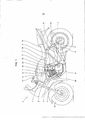
[0017] A figura 1 é uma vista lateral de uma motocicleta 2 provida com um motor refrigerado a ar 1 de acordo com uma primeira concretização da presente invenção. Um chassi da motocicleta 2 inclui um tubo dianteiro 3, uma armação principal 4 que se estende diagonalmente para trás a partir do tubo dianteiro 3, uma armação central 5 estendendo-se para baixo a partir da extremidade traseira da armação principal 4, uma armação inferior 6 estendendo-se para baixo a partir do tubo dianteiro 3, um esteio de assento 7 estendendo-se para trás a partir da armação principal 4, uma armação mediana 8 para conectar a extremidade inferior da armação central 5 ao centro da esteio de assento 7, e, uma armação de reforço 9 para conectar a armação inferior 6 à armação principal 4. Uma forquilha frontal 11 para suportar uma roda dianteira 10 é suportada de modo dirigível com o tubo dianteiro 3. Um guidão de direção 12 é conectado na forquilha dianteira 11. Uma forquilha dianteira 14 para suportar uma roda traseira 13 é oscilantemente suportada na direção vertical na porção traseira da armação central 5. Uma unidade amortecedora 15 é interposta entre o esteio de assento 7 e a forquilha traseira 14.[0017] Figure 1 is a side view of a
[0018] O motor 1 é suspenso para ser suportado com um suporte de apoio do motor 16 em uma porção em que a armação principal 4 é conectada na armação de reforço 9 enquanto sendo longitudinalmente suportada com a armação inferior 6 e armação central 5. A força do motor é transmitida na roda traseira 13 via uma correia de acionamento da roda traseira 17. A armação principal 4 é provida com um tanque de combustível 18 acima do motor 1. Um assento em tandem 19 é provido no esteio de assento 7 para o condutor e passageiro de carona. Um refrigerador de óleo refrigerado a ar 20 é disposto no lado frontal esquerdo do motor 1. Um tubo de exaustão 21 estende-se do motor, encurva-se para baixo e, ainda se estende para trás para ser conectado a um silencioso 22 em uma porção traseira.[0018] Motor 1 is suspended to be supported with a motor support bracket 16 in a portion where the
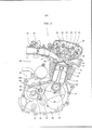
[0019] A figura 2 é uma vista lateral direita como vista seccional longitudinal do centro do motor refrigerado a ar 1. O motor 1 é formado por montar integralmente um motor de combustão interna 24 com uma transmissão 25. O motor 1 inclui cárteres do tipo meio corpo esquerdo e direito 26L e 26R e cobertas de cárter esquerda e direita 27L e 27R fora daqueles cárteres. O desenho mostra o estado em que o cárter direito 26R é removido para indicar o cárter esquerdo 26L e uma superfície topejante 26a entre os cárteres esquerdo e direito 26L e 26R. O desenho ainda mostra um eixo de manivela 28, um eixo principal 29 da transmissão, um eixo secundário 30 da transmissão, cada seção transversal de uma haste de deslocamento 31 e de um tambor de deslocamento 32, e, uma forquilha de deslocamento 33. Uma bomba de óleo 34 é mostrada abaixo do eixo de manivela.[0019] Figure 2 is a right side view as a longitudinal sectional view of the center of the air-cooled engine 1. Engine 1 is formed by integrally mounting an
[0020] Um bloco de cilindro 37, uma cabeça do cilindro 38 e uma coberta da cabeça do cilindro 39 são conectados na superfície superior do cárter 26. O desenho mostra o interior daqueles componentes. Um pistão 42 é conectado a um pino de manivela 40 comunicado com o eixo de manivela 28 via uma haste conectora 41. Uma câmara de combustão 43 é formada na superfície inferior da cabeça do cilindro 38 oposta à superfície superior do pistão 42. A extremidade dianteira da vela de ignição (não-mostrada) é externamente instalada para ficar na câmara de combustão 43. A cabeça do cilindro 38 contém o orifício de admissão 44, um orifício de exaustão 45, uma válvula de admissão 46 e uma válvula de exaustão 47. Um mecanismo de válvula 48 é disposto na camada limite entre a cabeça do cilindro 38 e uma coberta da cabeça do cilindro 39. O mecanismo de válvula 48 inclui um eixo de came 49, um eixo do oscilador de admissão 50, um eixo do oscilador de exaustão 51 e um braço do oscilador de admissão 52 e um braço do oscilador de exaustão 53. Um corpo da válvula reguladora 54 e um dispositivo de injeção de combustível 55 são conectados no orifício de admissão 44.[0020] A
[0021] A bomba de óleo 34 dentro do cárter 26 é acionada em as sociação com o eixo de manivela 28 via uma engrenagem para sugar o óleo lubrificante armazenado em um tanque de óleo 56 de modo a ser fornecido à cabeça do cilindro 38, ao eixo principal 29 e ao eixo secundário 30 da transmissão e ainda ao eixo de manivela 28 via o resfriador de óleo 20.[0021] The
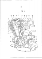
[0022] A figura 3 é uma vista do lado esquerdo mostrando a seção transversal da câmara de correia de came 59 do motor refrigerado a ar 1 e o interior do cárter esquerdo 26L enquanto removendo a coberta do cárter esquerdo 27L. A câmara de correias de came 59 é formada para penetrar no bloco de cilindro 37, na cabeça do cilindro 38 e na coberta da cabeça do cilindro 39. Uma roda dentada acionada de eixo de came 60 é provida na extremidade esquerda do eixo de came 49. Uma correia de came 62 é provida entre a roda dentada acionada 60 e uma roda dentada acionadora 61 de eixo de came enquanto penetrando na câmara de correia de came 59 de tal modo que o eixo de came 49 é acionado para girar pela rotação do eixo de manivela 28.[0022] Figure 3 is a left side view showing the cross section of the
[0023] Um gerador de CA 63 é provido na extremidade esquerda do eixo de manivela 28. O desenho mostra um rotor 63A provido na extremidade do eixo de manivela 28 e um estator 63B fixado na coberta do cárter esquerdo 27L. O eixo secundário 30 da transmissão serve como um eixo de saída tendo a extremidade esquerda provida com uma roda dentada acionadora de roda traseira 64 em torno do que uma correia acionadora de roda traseira 17 é enrolada.[0023] An
[0024] Um suspensor de motor 65 é formado na porção superior na superfície traseira da cabeça do cilindro 38 de modo a suspender o motor 1 a ser suportado pelo suporte de apoio do motor 16 (figura 1) na porção em que a armação principal 4 é conectada à armação de reforço 9.[0024] A
[0025] Um reservatório de óleo 69 como uma porção de recesso é formado no interior traseiro da cabeça do cilindro. O reservatório de óleo 69 acumula gotículas de óleo que tem sido suprido na cabeça do cilindro 38 via bomba de óleo 34 para lubrificar o eixo de came 49 e similar. Um sensor de temperatura do óleo 70 é disposto para penetrar na parede externa na superfície traseira da cabeça do cilindro 38 en- quanto tendo uma porção de detecção 70a como extremidade dianteira trazida no reservatório de óleo 69. A superfície do fundo do reservatório de óleo 69 fica distante da porção de detecção 70a no sensor de temperatura do óleo por uma distância d. No caso em que uma substância estranha tal como areia é acumulada no fundo do sensor de temperatura do óleo 70, a porção de detecção 70a do sensor de temperatura do óleo 70 não é trazida para contato com tal substância estranha para manter a precisão de detecção. Uma superfície de sede da montagem do sensor de temperatura do óleo 70 fica em paralelo com a superfície da sede de montagem do corpo da válvula reguladora 54. Consequentemente, um eixo 70x do sensor de temperatura do óleo 70 fica em paralelo com um eixo 54x da superfície da sede de montagem do corpo da válvula reguladora 54.[0025] An
[0026] O sensor de temperatura do óleo 70 é disposto em uma porção ausente de aleta 71c como uma parte descontínua da pluralidade de aletas refrigeradas a ar 71 abaixo do suspensor de motor 65. Uma aleta da posição mais baixa simples 71a é deixada sem ser removida abaixo do sensor de temperatura do óleo 70 da cabeça do cilindro 38 para manter a resistência da cabeça do cilindro 38. O motor 1 é montado no veículo enquanto inclinando ligeiramente uma porção de cilindro 36 para frente. As aletas refrigeradas a ar 71 são também inclinadas para ter a água facilmente acumulada. Um furo de drenagem 71b é formado na aleta da posição mais baixa 71a para drenagem.[0026] The
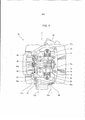
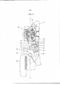
[0027] A figura 4 é uma vista do topo da cabeça do cilindro 38. Uma seta F representa a direção para frente. O óleo que tem atingido a cabeça do cilindro 38 via uma passagem de óleo lubrificante da cabeça do cilindro 74 formada na folga entre um parafuso prisioneiro 72 entre quatro parafusos prisioneiros para prender o cárter 26, o bloco de cilindro 37 e a cabeça do cilindro 38 e um furo de inserção de parafuso prisioneiro 73, então é fornecido a um furo central 49a do eixo de came 49 via um trajeto de comunicação 74a da passagem de óleo lubrificante da cabeça do cilindro 74. O óleo é ainda disperso em torno de um pequeno furo na direção radial formado no eixo de came 49 de modo a ser fornecido a uma porção deslizante entre cada extremidade dos braços do oscilador 52, 53 e o came, a porção deslizante entre os eixos do oscilador 50, 51 e os braços do oscilador 52, 53, cada porção deslizante das hastes de válvula 46a, 47a da válvula de admissão 46 e válvula de exaustão 47 e a correia de came 62. Após lubrificar os componentes acima mencionados a serem lubrificados, o óleo disperso no espaço é finalmente coletado no tanque de óleo 56 via a câmara de correia de came 59 como gotículas de óleo. Algum do óleo aderido na superfície da parede traseira dentro da cabeça do cilindro para gotejar para baixo é acumulado no reservatório de óleo 69. O sensor de temperatura do óleo 70 é disposto de tal modo que a porção de detecção 70a na extremidade dianteira é posicionada no reservatório de óleo 69. Como mostrado na figura 4, o reservatório de óleo 69 é formado na traseira da câmara de correia de came 59.[0027] Figure 4 is a view from the top of the
[0028] O reservatório de óleo 69 e o sensor de temperatura do óleo 70 são dispostos na parte esquerda traseira da cabeça do cilindro 38. Ao contrário, o orifício de admissão 44 é aberto na parte direita traseira da cabeça do cilindro 38. A extremidade externa do eixo do sensor de temperatura do óleo 70 é inclinado para ser direcionado para o centro do corpo do veículo.[0028] The
[0029] Como o reservatório de óleo 69 é disposto na parte traseira da cabeça do cilindro 38 e a porção de cilindro 36 é inclinada para frente, o óleo dificilmente flui para baixo para o reservatório de óleo 69. Como o óleo dificilmente flui para/fora do reservatório de óleo 69, a temperatura média do óleo pode ser detectada sem ser afetada pela flutuação da temperatura do óleo devido ao ciclo de combustão. Como a cabeça do cilindro 38 que constitui a câmara de combustão 43 é in- tegralmente provida com o reservatório de óleo 69, a temperatura do óleo no reservatório de óleo 69 flutua seguindo a temperatura da câmara de combustão 43. Isto torna possível detectar a temperatura com precisão maior. O reservatório de óleo 69 e o sensor de temperatura do óleo 70 são dispostos distantes do orifício de exaustão 45 de modo a serem menos afetados pelo calor do gás de exaustão. Isto torna possível realizar a detecção da temperatura de óleo com maior precisão.[0029] As the
[0030] Devido a dificuldade na medição direta da temperatura da câmara de combustão 43, a temperatura do óleo que se eleva via a parede adjacente à câmara de combustão 43 é detectada para indiretamente estimar a temperatura da câmara de combustão 43. Com base no valor estimado, a quantidade de injeção de combustível do dispositivo de injeção de combustível 55 (figura 2) é controlada.[0030] Due to the difficulty in directly measuring the temperature of the
[0031] Figura 5 é uma vista do topo mostrando a relação posicio- nal da cabeça do cilindro 38 com relação ao sistema de admissão e sistema de exaustão conectados na cabeça do cilindro 38. A linha C-C representa o centro do corpo do veículo. Um tubo de exaustão 21 é conectado ao orifício de exaustão 45 na superfície dianteira da cabeça do cilindro 38 e é encurvado para baixo para a direita para se estender mais para trás para ser conectado ao silencioso 22 (figura 1).[0031] Figure 5 is a view from the top showing the positional relationship of the
[0032] O corpo da válvula reguladora 54 é conectado no orifício de admissão 44 na superfície traseira da cabeça do cilindro 38 e possui uma extremidade a montante conectada a um filtro de ar 58 (vide figura 1) via o tubo de admissão 57. O tubo de admissão 57 contorna a armação central 5 do corpo do veículo no lado direito para ser encurvado para a esquerda. A superfície de montagem do sensor de temperatura do óleo 70 fica em paralelo com a superfície aberta do orifício de admissão, isto é, a superfície de montagem do corpo da válvula reguladora 54. Consequentemente, o eixo 70x do sensor de temperatura do óleo 70 fica em paralelo com o eixo 54x da superfície da sede de montagem do corpo da válvula reguladora 54. Isto torna possível melhorar a processabilidade da cabeça do cilindro 38.[0032] The
[0033] O dispositivo de injeção de combustível 55 é disposto na superfície superior do corpo de válvula reguladora 54 para fornecer o combustível da bomba de combustível 76 (vide figura 1) disposta na frente do filtro de ar 58 via um tubo 76a.Uma válvula borboleta 77 (vide figura 2) provida no corpo da válvula reguladora 54 é acionada por um mecanismo acionador de válvula reguladora 78 no lado direito do corpo da válvula reguladora 54. Um mecanismo de controle do corpo da válvula reguladora 79 é disposto no lado esquerdo do corpo da válvula reguladora 54. O mecanismo de controle do corpo da válvula reguladora 79 contém um sensor de ângulo de rotação, um sensor de pressão de admissão, um sensor de temperatura e similar.[0033] The
[0034] A concretização acima descrita provê os seguintes efeitos. (1) O sensor de temperatura do óleo 70 é disposto adjacente ao orifício de admissão 44 e à passagem de admissão nas temperaturas normais distantes do sistema de exaustão para não ser afetado pelo calor. Como a extremidade externa do sensor de temperatura do óleo 70 é inclinada para ser direcionada para o centro do veículo, a quantidade de projeção do sensor a partir da cabeça do cilindro 38 para a montante da passagem de admissão é reduzida. Isto torna possível evitar a interferência entre o acessório de motor e o sensor de temperatura do óleo 70 mesmo que o acessório de motor fosse trazido para estar próximo do bloco de cilindro 37 e da cabeça do cilindro 38. O eixo do sensor de temperatura de óleo 70 intersecta a parede externa da cabeça do cilindro. É indiferente se o eixo penetra ou não na parede externa da cabeça do cilindro. No caso de não penetração, a temperatura da câmara de combustão é estimada pela medição da temperatura da parede externa da cabeça do cilindro. (2) O sensor de temperatura do óleo 70 é capaz de detectar indiretamente a temperatura da câmara de combustão 43 pela detecção da temperatura do óleo que tem lubrificado o mecanismo de válvula 48. O sensor de temperatura do óleo 70 é protegido pelo suspensor de motor 65 e aletas refrigeradas a ar circundantes 71. O suspensor de motor que exibe alto desempenho de armazenagem de calor é provido próximo do sensor de temperatura do óleo 70 e a aleta refrigerada a ar 71 que exibe a função de resfriamento é removida. Isto torna possível manter a temperatura de óleo detectada pelo sensor de temperatura do óleo 70 alta e estimar a temperatura da câmara de combustão 43 acuradamente. (3) Como a superfície do fundo do reservatório de óleo 69 fica distante da porção de detecção na extremidade dianteira do sensor de temperatura do óleo 70 pela distância d, a substância estranha acumulada no fundo do reservatório de óleo 69 não é trazida em contato com a porção de detecção 70a do sensor de temperatura do óleo 70, assim melhorando a precisão da detecção. (4) A aleta da posição mais baixa 71a é deixada para manter a resistência da cabeça do cilindro 38. O sensor da temperatura do óleo 70 é disposto na superfície traseira do cilindro que inclina para frente similarmente que a abertura do orifício de admissão 44, água é tendente a ser acumulada na aleta na superfície traseira do cilindro que inclina para frente. Para isto, o furo de drenagem 61b é formado para drenar a água acumulada. (5) A superfície da sede de montagem do corpo da válvula reguladora 54 fica em paralela com a superfície da sede de montagem do sensor de temperatura do óleo 70. A posição para fixar a cabeça do cilindro não tem de ser mudada na perfuração e filetagem, assim melhorando a processabilidade da cabeça do cilindro 38.[0034] The embodiment described above provides the following effects. (1) The
[0035] Figura 1 é uma vista lateral de uma motocicleta com um motor refrigerado a ar de acordo com uma concretização da presente invenção.[0035] Figure 1 is a side view of a motorcycle with an air-cooled engine in accordance with an embodiment of the present invention.
[0036] Figura 2 é uma vista lateral direita mostrando uma seção transversal longitudinal do centro do motor refrigerado a ar.[0036] Figure 2 is a right side view showing a longitudinal cross section of the center of the air-cooled engine.
[0037] Figura 3 é uma vista lateral esquerda mostrando dentro do motor refrigerado a ar.[0037] Figure 3 is a left side view showing inside the air-cooled engine.
[0038] Figura 4 é uma vista do topo da cabeça do cilindro.[0038] Figure 4 is a view from the top of the cylinder head.
[0039] Figura 5 é uma vista do topo mostrando a relação posicio- nal entre a cabeça do cilindro e os sistemas de admissão/exaustão. Listagem de Referência 36 porção de cilindro 37 bloco de cilindro 38 cabeça do cilindro 39 coberta da cabeça do cilindro 42 pistão 43 câmara de combustão 44 orifício de admissão 45 orifício de exaustão 46 válvula de admissão 46a haste de válvula da válvula de admissão 47 válvula de exaustão 47a haste de válvula da válvula de exaustão 48 mecanismo de válvula 49 eixo de came 49a furo central do eixo de came 50 eixo do oscilador de admissão 51 eixo do oscilador de exaustão 52 braço do oscilador de admissão 53 braço do oscilador de exaustão 54 corpo da válvula reguladora 54x eixo da superfície da sede de montagem do corpo da válvu la reguladora 55 dispositivo de injeção de combustível 57 tubo de admissão 58 filtro de ar 65 suspensor de motor 69 reservatório de óleo 70 sensor de temperatura do óleo 70a porção de detecção 70x eixo do sensor de temperatura do óleo 70 71 aleta refrigerada a ar 71a aleta da posição mais baixa 71b furo de drenagem 71c porção ausente de aleta 72 parafuso prisioneiro 73 furo de inserção de parafuso prisioneiro 74 passagem de óleo lubrificante da cabeça do cilindro 74a trajeto de comunicação 76 bomba de combustível 77 válvula borboleta 78 mecanismo acionador de válvula reguladora 79 mecanismo de controle do corpo da válvula reguladora[0039] Figure 5 is a top view showing the positional relationship between the cylinder head and the intake / exhaust systems.
Claims (5)
Applications Claiming Priority (2)
| Application Number | Priority Date | Filing Date | Title |
|---|---|---|---|
| JP2008171405A JP4989570B2 (en) | 2008-06-30 | 2008-06-30 | Air-cooled engine |
| JP2008-171405 | 2008-06-30 |
Publications (2)
| Publication Number | Publication Date |
|---|---|
| BRPI0901546A2 BRPI0901546A2 (en) | 2010-04-06 |
| BRPI0901546B1 true BRPI0901546B1 (en) | 2021-01-12 |
Family
ID=41588414
Family Applications (1)
| Application Number | Title | Priority Date | Filing Date |
|---|---|---|---|
| BRPI0901546-9A BRPI0901546B1 (en) | 2008-06-30 | 2009-05-22 | air-cooled engine |
Country Status (2)
| Country | Link |
|---|---|
| JP (1) | JP4989570B2 (en) |
| BR (1) | BRPI0901546B1 (en) |
Families Citing this family (4)
| Publication number | Priority date | Publication date | Assignee | Title |
|---|---|---|---|---|
| JP5719657B2 (en) * | 2011-03-29 | 2015-05-20 | 本田技研工業株式会社 | Saddle riding vehicle |
| JP6222568B2 (en) * | 2014-03-18 | 2017-11-01 | 本田技研工業株式会社 | Cylinder head structure in internal combustion engine |
| JP2015178815A (en) * | 2014-03-19 | 2015-10-08 | ヤマハ発動機株式会社 | Saddle riding type vehicle |
| JP6162756B2 (en) * | 2015-07-09 | 2017-07-12 | 本田技研工業株式会社 | Air-oil cooled internal combustion engine |
Family Cites Families (5)
| Publication number | Priority date | Publication date | Assignee | Title |
|---|---|---|---|---|
| JPS59100696U (en) * | 1982-12-27 | 1984-07-07 | 本田技研工業株式会社 | motorcycle engine hanger |
| JP2006105063A (en) * | 2004-10-07 | 2006-04-20 | Ademusu Kk | Engine temperature sensor mounting structure for vehicular air cooled engine |
| JP4414362B2 (en) * | 2005-03-16 | 2010-02-10 | 本田技研工業株式会社 | Air-cooled engine warm-up control device |
| JP2006329160A (en) * | 2005-05-30 | 2006-12-07 | Honda Motor Co Ltd | Internal combustion engine |
| JP5032222B2 (en) * | 2007-07-03 | 2012-09-26 | 本田技研工業株式会社 | Air-cooled engine |
-
2008
- 2008-06-30 JP JP2008171405A patent/JP4989570B2/en not_active Expired - Fee Related
-
2009
- 2009-05-22 BR BRPI0901546-9A patent/BRPI0901546B1/en active IP Right Grant
Also Published As
| Publication number | Publication date |
|---|---|
| JP4989570B2 (en) | 2012-08-01 |
| BRPI0901546A2 (en) | 2010-04-06 |
| JP2010007646A (en) | 2010-01-14 |
Similar Documents
| Publication | Publication Date | Title |
|---|---|---|
| BRPI0901566A2 (en) | mounting frame of a motorcycle exhaust gas sensor | |
| BRPI0901546B1 (en) | air-cooled engine | |
| BR102013001159B1 (en) | Oil temperature sensor mounting frame for internal combustion engine | |
| EP2453121B1 (en) | Structure for attaching exhaust gas sensor | |
| BR112017020218B1 (en) | EXHAUST DEVICE FOR A MOTORCYCLE | |
| JP2010236484A (en) | Water-cooled internal combustion engine for vehicle | |
| US7258211B2 (en) | Rotary damper | |
| BR112019017635B1 (en) | INTAKE STRUCTURE FOR INTERNAL COMBUSTION ENGINES | |
| JP5364799B2 (en) | Device for guiding evaporated fuel to an internal combustion engine | |
| BR102019000263A2 (en) | INTERNAL COMBUSTION ENGINE | |
| BRPI0604743B1 (en) | INTERNAL COMBUSTION ENGINE AND MOTORCYCLE | |
| BR102019000234A2 (en) | saddle-mounted driving vehicle | |
| JP4252652B2 (en) | Engine temperature detection device for air-cooled engine | |
| BRPI0800914B1 (en) | motorcycle | |
| JP2010007646A5 (en) | ||
| BR102016015727A2 (en) | air / oil cooled internal combustion engine | |
| BR102019000676A2 (en) | SEAT-MOUNTED DRIVING VEHICLE | |
| BR112017002531B1 (en) | ENGINE AND VEHICLE UNIT TO BE ASSEMBLED | |
| BR112017002530B1 (en) | SADDLE TYPE ENGINE AND VEHICLE UNIT | |
| BRPI0803784B1 (en) | air cooled engine | |
| BR102013021742A2 (en) | saddle mount type vehicle fuel injection control device | |
| BRPI1002955B1 (en) | saddle type vehicle | |
| BR102012030477A2 (en) | SEAL TYPE VEHICLE | |
| JP6883066B2 (en) | Internal combustion engine structure | |
| BR112020003334A2 (en) | internal combustion engine |
Legal Events
| Date | Code | Title | Description |
|---|---|---|---|
| B03A | Publication of an application: publication of a patent application or of a certificate of addition of invention | ||
| B06F | Objections, documents and/or translations needed after an examination request according art. 34 industrial property law | ||
| B09A | Decision: intention to grant | ||
| B16A | Patent or certificate of addition of invention granted |
Free format text: PRAZO DE VALIDADE: 10 (DEZ) ANOS CONTADOS A PARTIR DE 12/01/2021, OBSERVADAS AS CONDICOES LEGAIS. |