BRPI0820176B1 - eye implantation device and kit to release an implant - Google Patents
eye implantation device and kit to release an implant Download PDFInfo
- Publication number
- BRPI0820176B1 BRPI0820176B1 BRPI0820176-5A BRPI0820176A BRPI0820176B1 BR PI0820176 B1 BRPI0820176 B1 BR PI0820176B1 BR PI0820176 A BRPI0820176 A BR PI0820176A BR PI0820176 B1 BRPI0820176 B1 BR PI0820176B1
- Authority
- BR
- Brazil
- Prior art keywords
- housing
- implant
- needle
- bar
- driver
- Prior art date
Links
Images


Classifications
-
- A—HUMAN NECESSITIES
- A61—MEDICAL OR VETERINARY SCIENCE; HYGIENE
- A61F—FILTERS IMPLANTABLE INTO BLOOD VESSELS; PROSTHESES; DEVICES PROVIDING PATENCY TO, OR PREVENTING COLLAPSING OF, TUBULAR STRUCTURES OF THE BODY, e.g. STENTS; ORTHOPAEDIC, NURSING OR CONTRACEPTIVE DEVICES; FOMENTATION; TREATMENT OR PROTECTION OF EYES OR EARS; BANDAGES, DRESSINGS OR ABSORBENT PADS; FIRST-AID KITS
- A61F9/00—Methods or devices for treatment of the eyes; Devices for putting-in contact lenses; Devices to correct squinting; Apparatus to guide the blind; Protective devices for the eyes, carried on the body or in the hand
- A61F9/0008—Introducing ophthalmic products into the ocular cavity or retaining products therein
- A61F9/0017—Introducing ophthalmic products into the ocular cavity or retaining products therein implantable in, or in contact with, the eye, e.g. ocular inserts
-
- A—HUMAN NECESSITIES
- A61—MEDICAL OR VETERINARY SCIENCE; HYGIENE
- A61M—DEVICES FOR INTRODUCING MEDIA INTO, OR ONTO, THE BODY; DEVICES FOR TRANSDUCING BODY MEDIA OR FOR TAKING MEDIA FROM THE BODY; DEVICES FOR PRODUCING OR ENDING SLEEP OR STUPOR
- A61M37/00—Other apparatus for introducing media into the body; Percutany, i.e. introducing medicines into the body by diffusion through the skin
- A61M37/0069—Devices for implanting pellets, e.g. markers or solid medicaments
-
- A—HUMAN NECESSITIES
- A61—MEDICAL OR VETERINARY SCIENCE; HYGIENE
- A61M—DEVICES FOR INTRODUCING MEDIA INTO, OR ONTO, THE BODY; DEVICES FOR TRANSDUCING BODY MEDIA OR FOR TAKING MEDIA FROM THE BODY; DEVICES FOR PRODUCING OR ENDING SLEEP OR STUPOR
- A61M5/00—Devices for bringing media into the body in a subcutaneous, intra-vascular or intramuscular way; Accessories therefor, e.g. filling or cleaning devices, arm-rests
- A61M5/178—Syringes
- A61M5/31—Details
- A61M5/32—Needles; Details of needles pertaining to their connection with syringe or hub; Accessories for bringing the needle into, or holding the needle on, the body; Devices for protection of needles
- A61M5/3205—Apparatus for removing or disposing of used needles or syringes, e.g. containers; Means for protection against accidental injuries from used needles
- A61M5/321—Means for protection against accidental injuries by used needles
- A61M5/322—Retractable needles, i.e. disconnected from and withdrawn into the syringe barrel by the piston
-
- A—HUMAN NECESSITIES
- A61—MEDICAL OR VETERINARY SCIENCE; HYGIENE
- A61K—PREPARATIONS FOR MEDICAL, DENTAL OR TOILETRY PURPOSES
- A61K9/00—Medicinal preparations characterised by special physical form
- A61K9/0012—Galenical forms characterised by the site of application
- A61K9/0048—Eye, e.g. artificial tears
- A61K9/0051—Ocular inserts, ocular implants
-
- A—HUMAN NECESSITIES
- A61—MEDICAL OR VETERINARY SCIENCE; HYGIENE
- A61M—DEVICES FOR INTRODUCING MEDIA INTO, OR ONTO, THE BODY; DEVICES FOR TRANSDUCING BODY MEDIA OR FOR TAKING MEDIA FROM THE BODY; DEVICES FOR PRODUCING OR ENDING SLEEP OR STUPOR
- A61M2210/00—Anatomical parts of the body
- A61M2210/06—Head
- A61M2210/0612—Eyes
Abstract
DISPOSITIVO PARA IMPLANTAÇÃO OCULAR. A presente invenção refere-se a um dispositivo de implantação ocular que compreende um alojamento tendo um eixo longitudinal, uma agulha configurada para receber um implante, e um êmbolo e uma barra operativamente acoplados juntos. O êmbolo e a barra são dispostas no alojamento e são coletivamente e translacionalmente móveis ao longo do eixo longitudinal do alojamento. A barra é configurada para ser receptível dentro de pelo menos uma porção da agulha para possibilitar que a barra se mova em um implante nela. Um acionador é operativamente engatado com o êmbolo de modo que o movimento do acionador em uma direção alinhada com o eixo longitudinal do alojamento resulte em movimento translacional do êmbolo e da barra ao longo do eixo longitudinal do alojamento de modo a liberar o implante através da agulha em um sítio-alvo. Uma modalidade alternativa do dispositivo usa uma agulha retrátil para liberar o implante.DEVICE FOR EYE IMPLANTATION. The present invention relates to an eye implantation device that comprises a housing having a longitudinal axis, a needle configured to receive an implant, and a plunger and bar operatively coupled together. The plunger and bar are arranged in the housing and are collectively and translationally movable along the longitudinal axis of the housing. The bar is configured to be receptive within at least a portion of the needle to allow the bar to move on an implant in it. A driver is operatively engaged with the plunger so that the movement of the driver in a direction aligned with the longitudinal axis of the housing results in translational movement of the plunger and bar along the longitudinal axis of the housing in order to release the implant through the needle at a target site. An alternative embodiment of the device uses a retractable needle to release the implant.
Description
[001] O presente documento de patente reivindica o benefício da data de depósito de acordo com 35 U.S.C. §119(e) dos Pedidos de Patente Provisórios U.S. 60/986.464, depositado em 8 de novembro de 2007, e 61/075.786, depositado em 26 de junho de 2008, que são aqui incorporados, a título de referência, na sua totalidade.[001] This patent document claims the benefit of the filing date in accordance with 35 USC §119 (e) of US Provisional
[002] A presente invenção refere-se a um dispositivo para liberar implantes oculares no vítreo do olho. Especificamente, a invenção refere-se a um injetor ergonomicamente conformado contendo uma agulha capaz de perfurar o olho e liberar um implante no vítreo do olho.[002] The present invention relates to a device for releasing ocular implants into the vitreous of the eye. Specifically, the invention relates to an ergonomically shaped injector containing a needle capable of piercing the eye and releasing an implant in the vitreous of the eye.
[003] Uma dificuldade primária em tratar doenças do olho é a inabilidade de introduzir fármacos ou agentes terapêuticos no olho e manter esses fármacos ou agentes em uma concentração terapêuticamente eficaz no olho pela duração necessária. A administração sistêmica pode não ser uma solução ideal porque, muitas vezes, níveis inaceitavelmente altos de dosagem sistêmica são necessários para alcançar concentrações intraoculares eficazes aumentando assim a incidência de efeitos colaterais inaceitáveis dos fármacos. Uma instilação ou aplicação ocular simples não é uma alternativa aceitável em muitos casos porque o fármaco pode ser rapidamente lavado pela ação da lágrima ou pode, de outro modo, ser esvaziado do olho na circulação geral. Injeções supracoroidais de soluções de fármaco têm sido executadas, mas outra vez a disponibilidade do fármaco tem vida curta. Em resumo, os métodos disponíveis tornam difícil manter os níveis terapêuticos de fármaco por períodos de tempo adequados.[003] A primary difficulty in treating diseases of the eye is the inability to introduce drugs or therapeutic agents into the eye and keep those drugs or agents in a therapeutically effective concentration in the eye for the required duration. Systemic administration may not be an ideal solution because, often, unacceptably high levels of systemic dosage are necessary to achieve effective intraocular concentrations thereby increasing the incidence of unacceptable side effects of drugs. A simple eye instillation or application is not an acceptable alternative in many cases because the drug can be quickly washed away by the action of the tear or can otherwise be emptied from the eye into the general circulation. Supracoroidal injections of drug solutions have been performed, but again the availability of the drug is short-lived. In summary, the methods available make it difficult to maintain therapeutic drug levels for adequate periods of time.
[004] Os esforços para abordar este problema têm levado ao desenvolvimento de dispositivos de liberação de fármaco, ou implantes, que pode ser implantados no olho de modo que uma quantidade controlada de fármaco desejado pode ser liberada constantemente por um período de diversos dias, semanas ou até mesmo meses. Muitos tais dispositivos foram previamente relatados. Vide, por exemplo, a patente U.S. 4.853.224, que descreve implantes biocompatíveis para introdução em um segmento anterior ou um segmento posterior de um olho, para tratamento de uma condição ocular. Além disso, a Patente U.S. 5.164.188 descreve um método para tratar uma condição ocular através da introdução de um implante biodegradável que compreende fármacos de interesse no espaço supracoroidal ou partes planas do olho. Vide também as Patentes U.S. 5.824.072; 5.476.511; 4.997.652; 4.959.217; 4.668.506 e 4.144.317.[004] Efforts to address this problem have led to the development of drug delivery devices, or implants, that can be implanted in the eye so that a controlled amount of desired drug can be released constantly over a period of several days, weeks or even months. Many such devices have been previously reported. See, for example, U.S. Patent 4,853,224, which describes biocompatible implants for insertion into an anterior segment or a posterior segment of an eye, for treating an eye condition. In addition, U.S. Patent 5,164,188 describes a method for treating an eye condition by introducing a biodegradable implant that comprises drugs of interest in the supracoroidal space or flat parts of the eye. See also U.S. Patents 5,824,072; 5,476,511; 4,997,652; 4,959,217; 4,668,506 and 4,144,317.
[005] Outros métodos incluem ancorar um plugue ou tacha contendo um fármaco na esclerótica do olho (vide, por exemplo, Patente U.S. 5.466.233).[005] Other methods include anchoring a plug or tack containing a drug to the sclera of the eye (see, for example, U.S. Patent 5,466,233).
[006] Existem vários sítios no olho para implantação de um dispositivo de liberação de fármaco ou implante, tal como o vítreo do olho, câmaras anterior e posterior do olho, ou outras áreas do olho incluindo espaços intrarretiniano, sub-retiniano, intracoroidiano, supra- coroidiano, intraesclerótica, episclerótico, subconjutival, intracorneano ou epicorneano. Onde quer que seja o local desejado de implantação, todos os métodos de implantação típicos requerem procedimentos cirúrgicos relativamente invasivos colocando um risco de trauma excessivo ao olho, e exige excessivo manuseio do implante. Por exemplo, em um método típico para substituição no vítreo, é feita uma incisão através da esclerótica, e o implante é inserido em e depositado no local desejado no vítreo, usando fórceps ou outro dispositivo de agarrar manual similar. Uma vez depositado, o fórceps (ou dispositivo de agarrar) é removido, e a incisão é fechada suturada. Alternativamente, uma incisão pode ser feita através da esclerótica, um trocar pode ser avançado através da incisão e então o implante pode ser liberado através do trocar. Podem ser empregados métodos similares para liberar implantes a outros locais, por exemplo, implantação na câmara anterior do olho através de uma incisão na córnea.[006] There are several sites in the eye for implanting a drug or implant delivery device, such as the vitreous of the eye, anterior and posterior chambers of the eye, or other areas of the eye including intraretinal, subretinal, intracoroidal, supra spaces - choroidal, intra-sclerotic, episclerotic, subconjutival, intracornean or epicornian. Wherever the desired implantation site is, all typical implantation methods require relatively invasive surgical procedures that pose a risk of excessive trauma to the eye, and require excessive handling of the implant. For example, in a typical method for replacing the vitreous, an incision is made through the sclera, and the implant is inserted into and deposited at the desired location in the vitreous, using forceps or another similar handgrip. Once deposited, the forceps (or grasping device) is removed, and the incision is closed with a suture. Alternatively, an incision can be made through the sclera, an trocar can be advanced through the incision and then the implant can be released through the trocar. Similar methods can be used to release implants to other sites, for example, implantation in the anterior chamber of the eye through an incision in the cornea.
[007] Existem numerosos obstáculos de tais técnicas para libera ção de implante. O extenso manuseio do implante é necessário nessas técnicas, criando um risco em que o implante seja avariado no processo. Muitos implantes são baseados em polímero e são relativamente frágeis. Se porções dos implantes estão avariadas e quebradas, uma eficaz dose terapêutica liberada pelo implante que foi colocado será significantemente alterada. Além disso, torna-se inerentemente difícil usar esses métodos para alcançar uma reprodutiva substituição de paciente para paciente. Adicionalmente, todas essas técnicas exigem uma incisão ou perfuração no olho, grande o bastante para exigir sutura. Por conseguinte, tais técnicas são tipicamente executadas em um ambiente cirúrgico.[007] There are numerous obstacles to such techniques for implant release. Extensive handling of the implant is necessary in these techniques, creating a risk that the implant will be damaged in the process. Many implants are polymer based and are relatively fragile. If portions of the implants are damaged and broken, an effective therapeutic dose released by the implant that has been placed will be significantly altered. In addition, it becomes inherently difficult to use these methods to achieve reproductive patient-to-patient replacement. In addition, all of these techniques require an incision or perforation in the eye, large enough to require suturing. Therefore, such techniques are typically performed in a surgical environment.
[008] Muitas considerações afetam o projeto e eficácia de um dispositivo de liberação de implante. Primeiro, é importante assegurar que o implante é consistentemente liberado no objetivo com cada aplicação. Segundo, porque a terapia do implante muitas vezes exige numerosas aplicações e o custo de fornecer o implante deve ser considerado.[008] Many considerations affect the design and effectiveness of an implant release device. First, it is important to ensure that the implant is consistently released on purpose with each application. Second, because implant therapy often requires numerous applications and the cost of providing the implant must be considered.
[009] Com base no já mencionado, permanece a necessidade por um dispositivo mais fácil, conveniente, menos invasivo e menos traumático, para liberar implantes no olho. Além disso, permanece a necessidade por um dispositivo mais controlado de liberar implantes no olho.[009] Based on the aforementioned, there remains a need for an easier, convenient, less invasive and less traumatic device to release implants in the eye. In addition, there remains a need for a more controlled device to deliver implants to the eye.
[0010] A presente invenção é direcionada a um dispositivo e um método para liberar implantes oculares a locais desejados no olho. O dispositivo compreende um alojamento que tem um acionador que é comunicativamente ligado a um êmbolo. Uma força aplicada ao acionador em uma direção paralela ao eixo longitudinal do alojamento é usada para liberar o implante ao local desejado do olho. Antes da liberação do implante, o estado do implante é visualmente observável pelo usuário.[0010] The present invention is directed to a device and a method for delivering ocular implants to desired locations in the eye. The device comprises a housing that has a driver that is communicatively connected to a plunger. A force applied to the driver in a direction parallel to the longitudinal axis of the housing is used to release the implant to the desired location in the eye. Before the implant is released, the state of the implant is visually observable by the user.
[0011] Em um aspecto da invenção, um dispositivo de implantação ocular compreende um alojamento tendo um eixo longitudinal e uma agulha que se estende do alojamento, em que um lúmen da agulha é configurado para receber um implante. O dispositivo adicionalmente compreende um êmbolo longitudinalmente disposto dentro do alojamento e uma barra que se estende longitudinalmente operativamente acoplada a ele. O êmbolo e a barra são coletivamente, translacionalmente móveis ao longo do eixo longitudinal do alojamento. A barra é configurada para ser receptível dentro de pelo menos uma porção do lúmen. O dispositivo também compreende um acionador configurado para um movimento controlado, guiado, tal como o movimento que está sendo controlado e guiado por um usuário e por uma porção do alojamento. O acionador é operativamente engatado com o êmbolo de modo que o movimento do acionador em uma direção alinhada com o eixo longitudinal do alojamento resulte em movimento translacional do êmbolo e da barra ao longo do eixo longitudinal do alojamento. Adicionalmente, o acionador é capaz de movimento em uma direção normal ao eixo longitudinal do alojamento que não resulta em movimento do êmbolo e da barra.[0011] In one aspect of the invention, an eye implantation device comprises a housing having a longitudinal axis and a needle extending from the housing, wherein a lumen of the needle is configured to receive an implant. The device additionally comprises a plunger longitudinally disposed within the housing and a longitudinally extending bar operatively coupled thereto. The plunger and bar are collectively translationally movable along the longitudinal axis of the housing. The bar is configured to be receptive within at least a portion of the lumen. The device also comprises a trigger configured for controlled, guided movement, such as the movement being controlled and guided by a user and a portion of the housing. The actuator is operatively engaged with the plunger so that the movement of the actuator in a direction aligned with the longitudinal axis of the housing results in translational movement of the plunger and bar along the longitudinal axis of the housing. Additionally, the actuator is capable of movement in a direction normal to the longitudinal axis of the housing which does not result in movement of the piston and the bar.
[0012] Em um outro aspecto da invenção, um dispositivo de implantação ocular compreende um alojamento tendo um eixo longitudinal e uma agulha estendendo-se longitudinalmente do alojamento, com a agulha tendo um lúmen que se estende através dele. O lúmen da agulha é configurado para receber um implante. O dispositivo adicionalmente compreende um êmbolo longitudinalmente posicionado dentro do alojamento e uma barra estendendo-se dele. O êmbolo e a barra são translacionalmente móveis ao longo do eixo longitudinal do alojamento de uma posição inicial, e a barra é receptível dentro de pelo menos uma porção do lúmen da agulha. O dispositivo também compreende um eixo guia que é fixamente posicionado dentro do alojamento em comunicação com a agulha, com o eixo guia cooperativamente recebendo o êmbolo e a barra mediante seu movimento translacional e um acionador comunicativamente ligado ao êmbolo. O acionador é longitudinalmente móvel de uma primeira posição com relação ao alojamento mediante aplicação ao acionador de uma força alinhada com o eixo longitudinal do alojamento. O movimento do acionador corresponde com o movimento translacional do êmbolo da posição inicial. O alojamento tem uma janela disposta aí para visualmente determinar o estado de um implante disposto no alojamento.[0012] In another aspect of the invention, an eye implantation device comprises a housing having a longitudinal axis and a needle extending longitudinally from the housing, with the needle having a lumen extending through it. The lumen of the needle is configured to receive an implant. The device additionally comprises a piston longitudinally positioned within the housing and a bar extending from it. The plunger and bar are translationally movable along the longitudinal axis of the housing from an initial position, and the bar is receptive within at least a portion of the needle lumen. The device also comprises a guide shaft that is fixedly positioned inside the housing in communication with the needle, with the guide shaft cooperatively receiving the plunger and the bar by means of its translational movement and an actuator communicatively connected to the plunger. The actuator is longitudinally movable from a first position with respect to the housing by applying to the actuator a force aligned with the longitudinal axis of the housing. The movement of the actuator corresponds to the translational movement of the plunger from the initial position. The housing has a window arranged there to visually determine the state of an implant arranged in the housing.
[0013] A figura 1 é uma vista explodida de um dispositivo de implantação ocular de acordo com uma modalidade da presente invenção.[0013] Figure 1 is an exploded view of an eye implantation device according to an embodiment of the present invention.
[0014] A figura 2 é uma vista lateral em elevação do dispositivo de implantação ocular da figura 1 em uma configuração de operação inicial com a porção do alojamento esquerda removida para melhor mostrar seus componentes internos.[0014] Figure 2 is a side elevation view of the eye implantation device of figure 1 in an initial operating configuration with the left housing portion removed to better show its internal components.
[0015] A figura 3 é uma vista parcial aumentada da figura 2 mostrando o implante em detalhes.[0015] Figure 3 is an enlarged partial view of figure 2 showing the implant in detail.
[0016] A figura 4 é uma vista lateral em elevação do dispositivo de implantação ocular da figura 1 em uma configuração operacional subsequente com a porção de alojamento esquerda removida para melhor mostrar seus componentes internos do mesmo.[0016] Figure 4 is a side elevation view of the eye implantation device of figure 1 in a subsequent operational configuration with the left housing portion removed to better show its internal components.
[0017] A figura 5 é uma vista parcial aumentada da figura 4 mostrando o implante em detalhes.[0017] Figure 5 is an enlarged partial view of figure 4 showing the implant in detail.
[0018] A figura 6 é uma vista lateral em elevação do dispositivo de implantação ocular da figura 1 em uma outra configuração operacional subsequente com a porção de alojamento esquerda removida para melhor mostrar os componentes internos do mesmo.[0018] Figure 6 is a side elevation view of the eye implantation device of figure 1 in another subsequent operational configuration with the left housing portion removed to better show its internal components.
[0019] A figura 7 é uma vista parcial aumentada da figura 6 mostrando o implante em detalhes.[0019] Figure 7 is an enlarged partial view of Figure 6 showing the implant in detail.
[0020] A figura 8 é uma vista lateral em elevação do dispositivo de implantação ocular da figura 1 em uma outra configuração operacional subsequente com a porção de alojamento esquerda removida para melhor mostrar os componentes internos do mesmo.[0020] Figure 8 is a side elevation view of the eye implantation device of figure 1 in another subsequent operational configuration with the left housing portion removed to better show its internal components.
[0021] A figura 9 é uma vista parcial aumentada da figura 8 mostrando o implante em detalhes.[0021] Figure 9 is an enlarged partial view of Figure 8 showing the implant in detail.
[0022] A figura 10 é uma vista lateral em elevação do dispositivo de implantação ocular da figura 1 em uma outra configuração operacional subsequente com a porção de alojamento esquerda removida para melhor mostrar os componentes internos do mesmo.[0022] Figure 10 is a side elevation view of the eye implantation device of figure 1 in another subsequent operational configuration with the left housing portion removed to better show its internal components.
[0023] A figura 11 é uma vista parcial aumentada da figura 2 mostrando o implante em detalhes.[0023] Figure 11 is an enlarged partial view of figure 2 showing the implant in detail.
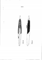
[0024] As figuras 12-17 são vistas em perspectiva do dispositivo de implantação ocular de acordo com suas modalidades alternativas do mesmo.[0024] Figures 12-17 are seen in perspective of the ocular implantation device according to its alternative modalities thereof.
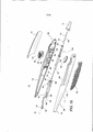
[0025] A figura 18 é uma vista explodida de um dispositivo de implantação ocular de acordo com uma outra modalidade da presente invenção.[0025] Figure 18 is an exploded view of an eye implantation device according to another embodiment of the present invention.
[0026] A figura 19 é uma vista explodida de um dispositivo de implantação ocular de acordo com uma outra modalidade da presente invenção, cuja modalidade é similar à modalidade da figura 18.[0026] Figure 19 is an exploded view of an eye implantation device according to another embodiment of the present invention, the embodiment of which is similar to the embodiment of figure 18.
[0027] As figuras 20A-E são vistas laterais, em elevação, do dispositivo de implantação ocular da figura 19 em vários estágios de operação, com a porção de alojamento esquerda removida para melhor mostrar os componentes internos do mesmo.[0027] Figures 20A-E are side views, in elevation, of the ocular implantation device of figure 19 in various stages of operation, with the left housing portion removed to better show its internal components.
[0028] A figura 21 é uma vista parcial aumentada da figura 20B mostrando o implante em detalhes.[0028] Figure 21 is an enlarged partial view of figure 20B showing the implant in detail.
[0029] A figura 22 é uma vista parcial aumentada da figura 20C mostrando o implante em detalhes.[0029] Figure 22 is an enlarged partial view of figure 20C showing the implant in detail.
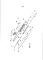
[0030] A figura 23 é uma vista explodida de um dispositivo de implantação ocular de acordo com uma outra modalidade da presente invenção.[0030] Figure 23 is an exploded view of an eye implantation device according to another embodiment of the present invention.
[0031] As figuras 24A-D são vistas laterais, em elevação, do dispositivo de implantação ocular da figura 23 em vários estágios de operação, com a porção de alojamento esquerda removida para melhor mostrar componentes internos do mesmo.[0031] Figures 24A-D are side views, in elevation, of the ocular implantation device of figure 23 in various stages of operation, with the left housing portion removed to better show its internal components.
[0032] A figura 25 é uma vista parcial aumentada da figura 24A mostrando o implante em detalhes.[0032] Figure 25 is an enlarged partial view of figure 24A showing the implant in detail.
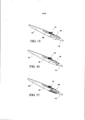
[0033] As figuras 26-27 são vistas laterais, em elevação, do dispositivo de implantação ocular de acordo com uma outra modalidade da presente invenção em vários estágios de operação, com a porção de alojamento direita removida para melhor mostrar componentes internos do mesmo.[0033] Figures 26-27 are side views, in elevation, of the ocular implantation device according to another embodiment of the present invention in various stages of operation, with the right housing portion removed to better show its internal components.
[0034] A figura 28 é uma vista em perspectiva de um dispositivo de implantação ocular de acordo com uma modalidade alternativa da presente invenção, cuja modalidade é similar à modalidade da figura 1.[0034] Figure 28 is a perspective view of an ocular implantation device according to an alternative embodiment of the present invention, the embodiment of which is similar to the embodiment of figure 1.
[0035] A figura 29 é uma vista plana de topo do dispositivo de implantação ocular da figura 28.[0035] Figure 29 is a top plan view of the ocular implantation device of figure 28.
[0036] A figura 30 é uma vista lateral em elevação do dispositivo de implantação ocular da figura 28.[0036] Figure 30 is a side elevation view of the ocular implantation device of figure 28.
[0037] É descrito um dispositivo de implantação ocular que fornece a um usuário uma indicação visual do estado de um implante a ser liberado em um tecido-alvo, antes da liberação. O dispositivo adicionalmente fornece uma indicação tátil do estado do implante a ser liberado, antes da liberação.[0037] An ocular implantation device is described that provides a user with a visual indication of the status of an implant to be released in a target tissue, prior to release. The device additionally provides a tactile indication of the status of the implant to be released, prior to release.
[0038] Como usado aqui, o termo "implantes" refere-se a disposi tivos de implantes oculares ou de liberação de fármaco que podem ser implantados em qualquer número de locais no olho e que podem liberar uma quantidade controlada de agentes bioativos ou terapêuticos imediatamente ou com o tempo. O termo implantes pode incluir microimplantes que têm uma área em seção transversal suficientemente pequena onde eles podem ser liberados por métodos e/ou usando dispositivos de acordo com a invenção que resultam em autovedante do olho em um sítio de perfuração associado com a liberação.[0038] As used here, the term "implants" refers to eye implant or drug delivery devices that can be implanted at any number of locations in the eye and that can release a controlled amount of bioactive or therapeutic agents immediately or over time. The term implants may include micro-implants that have a sufficiently small cross-sectional area where they can be released by methods and / or using devices according to the invention that result in self-sealing of the eye at a perforation site associated with the release.
[0039] Embora muitos dispositivos implantáveis possam ser adequados para uso com o dispositivo de implantação ocular descrito aqui, os dispositivos tendo uma conformação de tubo, tais como aqueles descritos na Patente U.S. 6.375.972, cuja matéria objeto é aqui incorporada na sua totalidade, são preferidos. Um exemplo de um dispositivo conformado em tubo inclui um tubo de poliimida com um núcleo de fármaco contido nele. O núcleo de fármaco pode ser feito por intermistura de álcool polivinílico (PVA) com uma substância de fármaco tal como fluocinolona acetonida. O núcleo pode ser injetado como uma pasta no tubo e aquecido para ligação transversal do PVA. O tubo pode ser cortado em um comprimento apropriado antes ou depois da inserção do núcleo de fármaco. Em cada extremidade do tubo, pode ser aplicado um revestimento permeável de fármaco, por exemplo, PVA. Alternativamente, um revestimento permeável pode ser usado em uma extremidade e um membro impermeável pode ser colocado na outra extremidade para uma taxa de liberação reduzida.[0039] Although many implantable devices may be suitable for use with the eye implantation device described here, devices having a tube shape, such as those described in US Patent 6,375,972, the subject matter of which is incorporated herein in its entirety, are preferred. An example of a tube shaped device includes a polyimide tube with a drug core contained therein. The drug core can be made by mixing polyvinyl alcohol (PVA) with a drug substance such as fluocinolone acetonide. The core can be injected as a paste into the tube and heated to cross-connect the PVA. The tube can be cut to an appropriate length before or after insertion of the drug core. At each end of the tube, a permeable drug coating, for example, PVA, can be applied. Alternatively, a permeable coating can be used on one end and an impermeable member can be placed on the other end for a reduced release rate.
[0040] Como usado aqui, os métodos de liberação de implantes, "autovedantes", para o olho, referem-se a métodos de introdução de implantes através de uma agulha e para um tecido-alvo de um olho do paciente sem a necessidade por sutura, ou outro dispositivo de fechamento similar, no sítio de perfuração da agulha. Tais métodos autovedantes não exigem que o sítio de perfuração vede completamente imediatamente mediante a retirada da agulha, mas de preferência, que qualquer vazamento inicial seja mínimo e dissipe rapidamente de modo que um cirurgião, ou outra pessoa igualmente versada na técnica, não seja compelido a suturar ou, de outro modo, fornecer outro dispositivo de fechamento similar ao sítio da perfuração. É preferido que todas as modalidades do dispositivo da presente invenção forneçam métodos autovedantes de liberação de implantes.[0040] As used here, "self-sealing" implant delivery methods for the eye refer to methods of inserting implants through a needle and target tissue into a patient's eye without the need for suture, or other similar closure device, at the needle piercing site. Such self-sealing methods do not require the piercing site to seal completely immediately upon withdrawal of the needle, but preferably, that any initial leak is minimal and dissipates quickly so that a surgeon, or another person equally skilled in the technique, is not compelled to suture or otherwise provide another closure device similar to the perforation site. It is preferred that all embodiments of the device of the present invention provide self-sealing methods of releasing implants.
[0041] Com referência agora aos desenhos, serão descritas várias modalidades ilustrativas. Nas figuras aqui, é mostrado um implante pré- carregado para as várias modalidades do dispositivo para propósitos descritivos e explanatórios. A figura 1 descreve uma modalidade do dispositivo de implantação ocular 10 compreendendo um alojamento 12, um conjunto de êmbolo 14, um conjunto de eixo guia 16, e uma tampa opcional 18. O dispositivo 10 adicionalmente compreende um acionador 20 disposto em uma abertura alongada do alojamento 22 e uma janela transparente 24 para visualização de um implante 26 (talvez melhor mostrado nas figuras 3 ou 5) dentro do alojamento 12. O alojamento 12 pode compreender uma porção de alojamento direita 28 e uma porção de alojamento esquerda 30, que podem ser unidas para formar o alojamento montado 12. O conjunto de êmbolo 14 é disposto dentro do alojamento 12 em uma extremidade proximal 32 do mesmo quando o dispositivo 10 é montado. Ele compreende um êmbolo 34, um plugue de êmbolo de insersor opcional 36 e uma mola 38. O êmbolo 34 e o plugue de êmbolo de insersor opcional 36 são configurados para encaixe juntos. O êmbolo 34 é longitudinalmente disposto dentro do alojamento 12 e inclui uma pluralidade de projeções radiais 40, e uma extremidade fechada 42, e uma extremidade aberta 44 para receber uma barra ou fio 46, que se estende radialmente. A barra 46 e o êmbolo 34 são operativamente acoplados de modo que o movimento do êmbolo 34 resulte em movimento da barra 46 resultando, desse modo, no êmbolo 34 e na barra 46 sendo coletivamente, translacionalmente móveis ao longo do eixo longitudinal 52 do alojamento 12. Uma fenda ou abertura alongada 48 é disposta perto da extremidade fechada 42 do êmbolo 34. A mola 38 tem uma porção de flange 50 que pode ser inserida na fenda 48 do êmbolo 34 para possibilitar que a mola 38 e o êmbolo 34 sejam operativamente conectados um ao outro.[0041] With reference now to the drawings, several illustrative modalities will be described. In the figures here, a pre-loaded implant is shown for the various modalities of the device for descriptive and explanatory purposes. Figure 1 describes an embodiment of the
[0042] O conjunto de êmbolo 14 e o conjunto de eixo guia 16 são alinhados com um eixo longitudinal 52 do alojamento 12. O conjunto de eixo guia 16 compreende uma barra 46, um tubo guia 54, um eixo guia 56, um batente na agulha 58, e uma agulha 60 e é disposto dentro do alojamento 12 quando o alojamento 12 está montado. Quando o dispositivo 10 está montado, o êmbolo 34 e a barra 46 são translacional- mente móveis ao longo do eixo longitudinal 52 do alojamento 12 de uma posição inicial, em que a barra 46 é receptível dentro de pelo menos uma porção de um lúmen 70 da agulha 60. Adicionalmente, a barra 46 é dimensionada para ajustar concentricamente dentro do tubo guia 54, e o tubo guia 54 é dimensionado para ajustar concentricamente dentro de pelo menos uma porção do eixo guia 56. O eixo guia 56 é fixamente posicionado dentro e é suportado pelo alojamento 12, em particular por arestas 62 do alojamento 12 e está em comunicação com a agulha 60 quando o dispositivo 10 está montado. Além disso, quando o dispositivo 10 é montado, o eixo guia 56 cooperativamente recebe o êmbolo 34 e a barra 46 mediante movimento de translação do mesmo. O eixo guia 56 pode incluir uma porção de eixo guia superior 64 e uma porção de eixo guia inferior 66, com a porção de eixo guia inferior 66 opcionalmente incluindo um dispositivo de retenção para impedir que o implante 26 seja involuntariamente ejetado do dispositivo 10 ou de ser desencaixado durante embarque. Na modalidade exemplar, o dispositivo de retenção é uma obstrução no núcleo 68 (talvez melhor mostrado na figura 3 ou 5). Embora a obstrução no núcleo 68 possa impedir o implante de ser involuntariamente desencaixado, ela não transpõe todo o percurso de viagem do implante 26. Por conseguinte, durante o uso do dispositivo 10, o implante 26 pode ser movido além da obstrução no núcleo 68 para ejeção do dispositivo 10 através de força suficiente no implante 26 pela barra 46.[0042] The
[0043] A janela 24 do alojamento 12 possibilita a um usuário visualizar o implante 26 no alojamento 12 antes dele ser movido para um lúmen 70 (talvez melhor mostrado na figura 3 ou 5) da agulha 60, que é configurado para receber o implante 26. Por conseguinte, um usuário pode visualizar o implante 26 para assegurar-se de que ele não foi avariado durante a expedição e manuseio ou involuntariamente ejetado. O usuário pode também usar a janela 24 para assegurar-se de que o implante 26 foi movido para o lúmen 70 da agulha 60 e, por conseguinte, pode ser liberado para o tecido-alvo, isto é, um usuário pode olhar através da janela 24 para ter certeza de que o implante 26 não está ainda visível e, por conseguinte, foi movido para o lúmen 70 da agulha 60.[0043]
[0044] O eixo guia 56 é preferivelmente aberto em ambas as extremidades 72, 74. Uma vez que a extremidade 72 do eixo guia 56 deslizantemente recebe o tubo guia 54, e a outra extremidade 74 é ajustada com o batente na agulha 58. O batente na agulha 58 é axialmente alinhado com a barra 46, o tubo guia 54, e o eixo guia 56 e é disposto em uma extremidade distal 76 do alojamento 12 quando o dispositivo 10 é montado. O batente na agulha 58 é configurado para receber a agulha 60 através dele de modo que a agulha 60 seja posicionada dentro do batente na agulha 58 e se projete da extremidade distal 76 do alojamento 12 quando o dispositivo 10 é montado. O batente na agulha 58 é configurado para receber a barra 46 e um implante 26 durante operação do dispositivo 10 de modo que o implante 26 possa ser acionado para o lúmen 70 da agulha 60 através da barra 46 durante operação. O implante 26 pode conter um agente bioativo. A tampa opcional 18 é anexada, por fricção, ao alojamento 12 blindando, desse modo, a agulha 60 quando o dispositivo 10 não está sendo usado.[0044] The
[0045] O acionador 20 é preferivelmente posicionado parcialmente dentro do alojamento 12 e é translacionalmente móvel ao longo da abertura alongada 22 no alojamento 12. O acionador 20 pode ser comunicativamente ligado ou operativamente engatado com o êmbolo 34 de modo que o movimento do acionador 20 em uma direção alinhada com o eixo longitudinal 52 do alojamento 12 resulte em movimento translacional do êmbolo 34 e da barra 46 ao longo do eixo longitudinal 52 do alojamento 12. O engate operativo pode também possibilitar que o acionador 20 seja capaz de movimento em uma direção normal para o eixo longitudinal 52 do alojamento 12 que não resulta em movimento do êmbolo 34 e da barra 46. Por exemplo, o acionador 20 pode ser operativamente engatado com o êmbolo 34 via uma das projeções radiais 40 do êmbolo 34 e pode ser acoplado à mola plana 38 de modo que uma força é aplicada ao acionador 20 pela mola 38.[0045] The
[0046] Quando o dispositivo 10 é montado, o acionador 20 pode ser longitudinalmente móvel de uma primeira posição 96 com relação ao alojamento 12 mediante aplicação ao acionador 20 de uma força alinhada com o eixo longitudinal 52 do alojamento 12. O acionador 20 inclui flanges 80 cooperativamente engatando uma porção do alojamento 12 para controlar e guiar o movimento do acionador 20. Em uma modalidade exemplar, a porção do alojamento 12 é um trilho 82 disposto no alojamento 12 para controlar e guiar o movimento do acionador 20 durante operação do dispositivo 10. O trilho 82 é dividido em seções contínuas proximal e distal 84, 86 através de uma saliência 88 disposta ao longo do trilho 82. A saliência 88 auxilia em impedir liberação inadvertida do implante 26 impedindo o acionador 20 de acidentalmente mover-se ao longo do trilho 82 da seção proximal 84 para a seção distal 86 do mesmo. Dispositivos de agarramento para o dedo 90 são opcionalmente dispostos em uma superfície externa 92 do alojamento 12 e uma superfície superior 94 do acionador 20. Os dispositivos de agarramento para o dedo 90 auxiliam com segurança na manipulação do dispositivo 10 por um usuário.[0046] When the
[0047] O dispositivo 10 pode adicionalmente incluir um membro de gabarito ou de guia 91 para acessar a localização do sítio de injeção em relação ao ponto de referência no olho, preferivelmente o limbo. As figuras 28-30 mostram uma modalidade do dispositivo de implantação ocular que é similar à modalidade da figura 1 e que tem uma variação levemente diferente do membro de guia do que do membro de guia da figura 1. Preferivelmente, uma borda externa ou vista no membro de guia 91 é alinhado no ou próximo ao ponto de referência, resultando no acesso a um sítio para injeção, o que seria uma distância predeterminada do ponto de referência. As distâncias úteis calibradas de um membro de guia 91 de dimensão particular são de cerca de 10 mm a cerca de 0,5 mm. Preferivelmente, de cerca de 6 mm a cerca de 2 mm. Mais preferivelmente cerca de 4 mm. Na presente modalidade, o membro de guia 91 inclui um membro planar conformado em asa na extremidade distal 76 do alojamento 12 em alinhamento horizontal com o eixo longitudinal 52 do alojamento 12. Um usuário pode usar o membro de guia 91 para auxiliar na determinação da localização de várias partes do olho em relação uma a outra, por exemplo, a córnea, o limbo, e a esclerótica, e em relação à agulha 60 do dispositivo 10 a ajudar a injetar, com precisão, a agulha 60 no olho para liberação do implante 26.[0047]
[0048] As figuras 2-11 mostram o dispositivo 10 em progressivos estágios de operação. Na figura 2, o dispositivo 10 está um uma configuração inicial, com o acionador 20 posicionado parcialmente dentro do alojamento 12 na seção proximal 84 do trilho 82. Na figura 2, o acionador 20 está na primeira posição 96. Na primeira posição 96, os flanges 80 do acionador 20 são dispostos dentro do alojamento 12 embora muito do restante do acionador 20 esteja disposto no exterior do alojamento 12. Além disso, os flanges 80 do acionador são adjacentes à saliência 88. Por conseguinte, de modo a mover o acionador 20 em direção à extremidade distal 76 do alojamento 12 liberando, desse modo, o implante 26 ao tecido-alvo, os flanges 80 devem clarear a saliência 88. Na configuração inicial do dispositivo, o acionador 20 é acionado mediante a mola plana 38 mantendo, desse modo, o acionador 20 na primeira posição 96. Um usuário pode visualizar o implante 26 no alojamento 12 quando o acionador 20 está na primeira posição 96, como mostrado na figura 3. Mediante aplicação de uma força descendente geralmente normal ao acionador 20, os flanges 80 do acionador 20 são verticalmente deslocados abaixo da saliência 88, como mostrado na figura 4. Nessa configuração, mais do acionador 20 é disposto dentro do alojamento 12 do que na configuração inicial mostrada na figura 2. Apesar do fato de que o acionador 20 move-se para baixo com relação ao eixo longitudinal 52 do alojamento 12, o êmbolo 34, que é operativamente acoplado ao acionador 20, não se move para baixo com relação ao eixo longitudinal 52 do alojamento 12. Ao contrário, o êmbolo 34 permanece verticalmente estacionário com respeito ao eixo longitudinal 52 do alojamento 12 por todo o uso e operação do dispositivo 10. Nessa configuração, um usuário pode usar a janela 24 para visualizar o implante 26 no alojamento 12, como mostrado na figura 5. Como pode ser visto nas figuras 3 e 5, o implante 26 está na mesma localização no alojamento 12 quando o alojamento 12 está na sua configuração inicial, mostrada na figura 2 e na configuração presente, mostrada na figura 4, isto é, o movimento do acionador 20 para baixo com relação ao eixo longitudinal 52 do alojamento 12 não afeta a localização do implante 26 durante este estágio de operação. Como mostrado na figura 6, uma vez que os flanges 80 do acionador estão abaixo da saliência 88, uma força aplicada ao acionador 20 na direção da extremidade distal 76 do alojamento 12 que é geralmente alinhada com o eixo longitudinal 52 do alojamento 12 causa movimento do acionador 20, o que causa um movimento translacional do êmbolo 34 e da barra 46 da posição inicial na seção proximal 84 do trilho 82 em direção à extremidade distal 76 do alojamento 12. Como descrito acima, quando o acionador 20 está na primeira posição 96, o trilho 82 guia o movimento do acionador 20 em uma direção normal ao eixo longitudinal 52 do alojamento 12 antes do movimento do acionador 20 em uma direção alinhada com o eixo longitudinal 52 do alojamento 12, o que resulta em movimento translacional da janela 24 e da barra 46 ao longo do eixo longitudinal 52 do alojamento 12.[0048] Figures 2-11 show the
[0049] Durante operação entre as configurações da figura 4 e figura 6, o implante 26 é contatado pela barra 46, que move o implante 26 para o lúmen 70 da agulha 60 de modo que o implante 26 seja preparado para liberação para o tecido-alvo, como pode ser visto na figura 7. A agulha 60 pode ser modificada, por exemplo, com inciso(s) (não- mostrado) no lúmen 70 da agulha 60 para reter o implante 26 e impedir ou eliminar ejeção acidental ou perda do implante. Depois dos flanges 80 do acionador terem clareado a saliência 88, a mola 38 fornece uma indicação tátil ao usuário de que o implante 26 está preparado para ejeção, já que o acionador 20 é forçado de modo ascendente em uma direção normal ao eixo longitudinal 52 do alojamento 12 para uma segunda posição 98 na seção distal 86 do trilho 82 pela força da mola 38, como mostrado na figura 8. Adicionalmente, o movimento relativo, ou sua falta do implante 26 é observável na janela transparente 24 do alojamento 12. Mais particularmente, nas figuras 2 a 5, o implante 26 é observável dentro da janela transparente 24, e nas figuras 6 a 9, o implante 26 foi acionado no lúmen 70 da agulha 60 e, desse modo, não é observável através da janela transparente 24, por conseguinte, indicando a um usuário que o implante 26 está preparado para ser liberado. Em qualquer evento, a janela transparente 24 ajuda na determinação da localização do implante 26. A janela transparente 24 pode conter uma lente aumentada. Nas figuras 6-9, o implante 26 é disposto no lúmen 70 da agulha 60 e está pronto para ejeção em um sítio-alvo. Uma vez que o implante 26 é, por conseguinte, depositado uma força aplicada ao acionador 20 que é geralmente alinhado com o eixo longitudinal 52 do alojamento 12 e na direção da extremidade distal 76 do alojamento 12 adicionalmente translada o êmbolo 34 e a barra 46 através da seção distal 86 do trilho 82, dirigindo, desse modo, o implante 26 através do lúmen 70 da agulha 60 para ejeção da agulha 60 e inserção em um tecido-alvo. Por conseguinte, quando o acionador 20 está na segunda posição 98, o trilho 82 guia o movimento do acionador 20 em uma direção alinhada com o eixo longitudinal 52 do alojamento 12 para adicional movimento translacional do êmbolo 34 e da barra 46 para liberar o implante 26.[0049] During operation between the configurations of figure 4 and figure 6, the
[0050] Para usar o dispositivo 10, um usuário pode inserir a agulha 60 do dispositivo 10, quando o dispositivo 10 está na configuração inicial mostrada na figura 2, em um olho objetivo. Na configuração inicial, o usuário pode verificar que o implante 26 está disposto no alojamento 12 através do uso da janela 24 do dispositivo 10 para visualizar o implante 26. Na figura 2, o acionador 20 está na primeira posição 96. O usuário pode aplicar uma força descendente e uma força ascendente ao acionador 20 para mover o acionador 20 e, portanto, o êmbolo 34 e a barra 46 em direção à extremidade distal 76 do alojamento 12. Como descrito acima, o êmbolo 34 é operativamente conectado à barra 46, que dirige o implante 26 através do lúmen 70 da agulha 60 em direção ao sítio-alvo uma vez que o acionador 20 está sendo movido em direção da extremidade distal 76 do alojamento 12 pelo usuário, resultando finalmente no implante 26 sendo ejetado do dispositivo 10.[0050] To use the
[0051] Na primeira posição 96, o acionador 20 é disposto na seção proximal 84 do trilho 82 em relação adjacente com a saliência 88. Um usuário pode pressionar descendentemente no acionador 20 para mover os flanges 80 abaixo da saliência 88. Uma vez que os flanges 80 clareiam a saliência 88, um usuário pode pressionar o acionador 20 em direção à extremidade distal do alojamento 12 movendo, desse modo, os flanges 80 do acionador além da saliência 88 (figura 6). O movimento do acionador ao longo do eixo longitudinal 52 do alojamento 12 causa ou translada para movimento similar do êmbolo 34 e da barra 46 ao longo do eixo longitudinal 52 do alojamento 12 resultando na barra 46 pressionando o implante 26 para o lúmen 70 da agulha 60 preparando, desse modo, o implante 26 para ejeção. O usuário pode verificar que o implante 26 não está mais no alojamento 12 olhando através da janela 24 do alojamento 12. Depois de o usuário ter movido o acionador 20 além da saliência 88, a mola 38 força o acionador 20 para a segunda posição 98, em que o acionador 20 está disposto na seção distal 86 do trilho 82 com os seus flanges 80 dispostos acima da saliência 88 (figura 8). O usuário pode continuar a pressionar o acionador 20 em direção à extremidade distal 76 do alojamento 12 causando, desse modo, um adicional movimento translacional do êmbolo 34 e da barra 46, por conseguinte, liberando o implante 26 ao sítio-alvo, como mostrado nas figuras 10 e 11. Preferivelmente, o sítio de perfuração é autovedante mediante remoção da agulha 60.[0051] In the
[0052] As figuras 12-17 são vistas em perspectiva do dispositivo de implantação ocular de acordo com modalidades alternativas do mesmo. Similarmente à modalidade mostrada na figura 1, os dispositivos de implantação ocular das figuras 12-17 compreendem um alojamento 102, um acionador 104 dispostos em uma abertura alongada do alojamento 128, uma janela transparente 106 para visualizar o implante 26 dentro do alojamento 102, e uma tampa opcional 112. Os componentes que são substancialmente similares àqueles das modalidades das figuras 18 e 19 são designados com os mesmo números de referência como usado nas figuras 18 e 19. Os dispositivos incluem várias modalidades de dispositivos de agarramento para o dedo opcionalmente dispostos sobre uma superfície externa do alojamento e uma superfície superior do acionador para ajudar a assegurar o manuseio do dispositivo por um usuário.[0052] Figures 12-17 are seen in perspective of the ocular implantation device according to alternative modalities thereof. Similar to the embodiment shown in figure 1, the eye implantation devices of figures 12-17 comprise a
[0053] As figuras 18 e 19 são vistas explodidas, em perspectiva, do dispositivo de implantação ocular de acordo com modalidades alternativas do mesmo. Os dispositivos 100 das figuras 18 e 19 são substancialmente similares, no entanto, o dispositivo de agarramento para o dedo opcional 170, 172 presentes nas duas modalidades são um tanto diferentes. A figura 18 corresponde substancialmente à modalidade mostrada na figura 12 e a figura 19 corresponde substancialmente à modalidade mostrada na figura 13. Os componentes que são os mesmos como uns aos outros ou substancialmente similares nos dispositivos das figuras 18 e 19 compartilham o mesmo número de referência.[0053] Figures 18 and 19 are exploded views, in perspective, of the ocular implantation device according to alternative modalities thereof. The
[0054] Ambas as modalidades compreendem um alojamento 102, um acionador 104, uma janela transparente 106, um conjunto de êmbolo 108, um conjunto de eixo guia 110, e uma tampa opcional 112. O alojamento 102 pode compreender uma porção de alojamento direita 114 e uma porção de alojamento esquerda 116, que podem se ligadas para formar o alojamento 102 montado. O conjunto de êmbolo 108 é disposto dentro do alojamento 102 em uma extremidade proximal 118 do mesmo quando o dispositivo 100 é montado. Ele compreende um êmbolo 120 e uma mola 122. O êmbolo 120 inclui uma pluralidade de projeções radiais 124, uma extremidade fechada 126 tendo uma abertura ou fenda alongada 128 formada aí, e uma extremidade aberta 130 para receber uma barra ou fio 132 se estendendo em projeção e um suporte de barra 134. Além disso, a extremidade aberta 130 do êmbolo 120 é dimensionada para ser deslizantemente recebida por um eixo guia 136 do conjunto de eixo guia 110. A mola 122 tem uma porção de flange 138 que pode ser inserida na fenda 128 do êmbolo 120 para permitir que a mola 122 e o êmbolo 120 sejam operativamente conectados um ao outro.[0054] Both embodiments comprise a
[0055] O conjunto de êmbolo 108 e o conjunto de eixo guia 110 são alinhados com um eixo longitudinal 140 do alojamento 102. O conjunto de eixo guia 110 compreende uma barra 132, o suporte de barra 134, o eixo guia 136, um batente de agulha 142, e uma agulha 144 e é disposto dentro do alojamento 102 quando o alojamento 102 é montado. A barra 132 é dimensionada para ajustar concentricamente dentro do eixo guia 136. O eixo guia 136 é fixamente posicionado dentro e é suportado pelo alojamento 102, em particular por arestas 146 do alojamento 102.[0055] The
[0056] O eixo guia 136 é preferivelmente aberto em ambas as extremidades 148, 150. Uma extremidade do eixo guia 148 deslizantemente recebe um êmbolo 136, e a outra extremidade 150 é ajustada com o batente de agulha 142 para acomodar a barra 132 e um implante 152 antes do implante 152 ser movido para o lúmen 154 (talvez melhor mostrado na figura 21) da agulha 144. O batente de agulha 142 é axialmente alinhado com a barra 132, o suporte de barra 134, e o eixo guia 136. A agulha 144 é posicionada no batente de agulha 142 e se projeta de uma extremidade distal 156 do alojamento 102. O batente de agulha 142 é configurado para receber a barra 132 e o implante 152 durante operação do dispositivo 100 de modo que o implante 152 pode ser acionado para o lúmen 154 da agulha 144 pela barra 132 durante operação. O implante 152 pode conter um agente bioativo. A tampa opcional 112 é anexada de modo friccional ao alojamento 102, blindando, desse modo, a agulha 144 quando o dispositivo 100 não está sendo usado.[0056] The
[0057] O acionador 104 é preferivelmente posicionado parcialmente dentro do alojamento 102 e é translacionalmente móvel ao longo de uma abertura alongada 158 no alojamento 102. O acionador 104 pode ser operativamente acoplado ao êmbolo 120 via uma das projeções radiais 124 e pode ser acoplado à mola chata 122 de modo que uma força seja aplicada ao acionador 104 pela mola 122. O acionador 104 inclui flanges 160 engatando cooperativamente um trilho 162 disposto no alojamento 102. O trilho 162 ajuda a guiar o acionador 104 durante operação do dispositivo 100. Na modalidade presente, o trilho 162 é dividido em seções contínuas proximal e distal 164, 166 por uma saliência 168 disposta ao longo do trilho 162. Os dispositivos de agarramento para o dedo 170, 172 são opcionalmente dispostos em uma superfície externa 174 do alojamento 102 e uma superfície superior 176 do acionador 104. Os dispositivos de agarramento para o dedo 170, 172 ajudam no manuseio seguro do dispositivo 100, por um usuário. Como indicado previamente, os dispositivos de agarramento para o dedo 170, 172 das modalidades mostradas nas figuras 18 e 19 diferem e, por conseguinte, têm diferentes números de referência.[0057] The
[0058] As figuras 20A-E, 21, e 22 mostram o dispositivo 100 em progressivos estágios de operação. Na figura 20A o dispositivo 100 está em uma configuração inicial, com o acionador 104 posicionado parcialmente dentro do alojamento 102 na seção proximal 164 do trilho 162. Nesta configuração inicial, o acionador 104 é acionado pela mola plana 122 de modo que uma força seja aplicada ao acionador 104. Mediante aplicação de uma força que é geralmente normal ao acionador 104, os flanges 160 do acionador 104 são verticalmente dispostos abaixo da saliência 168. Mediante aplicação de uma força que é geralmente alinhada com o eixo longitudinal 140 do alojamento 102, o acionador 104 é movido da seção proximal 164 do trilho 162 em direção à extremidade distal 156 do alojamento 102 clareando, desse modo, a saliência 168, como mostrado na figura 20B. Durante essa operação, o implante 152 é contatado pela barra 132, como mostrado na figura 21. Um dispositivo de retenção opcional 178 pode ser posicionado distalmente do implante 152 para impedir movimento do implante 152 durante expedição ou manuseio. Uma vez que o acionador 104 está além da saliência 168, o implante 152 é preparado para ejeção pela introdução ao lúmen 154 da agulha 144, como mostrado na figura 22. A agulha 144 pode ser modificada, por exemplo, com inciso(s) 180 no lúmen 154 da agulha 144 para reter o implante 152 e impedir ou eliminar ejeção acidental ou perda do implante 152. Nessa configuração, a mola 122 proporciona uma indicação tátil ao usuário de que o implante 152 está preparado para ejeção já que o acionador 104 é forçado ascendentemente para a seção distal 166 do trilho 162 pela força aplicada da mola 122. Adicionalmente, o movimento relativo, ou sua falta do implante 152 é observável na janela transparente 106 do alojamento 102, como mostrado nas figuras 21 e 22. A janela transparente 106 pode conter uma lente aumentada. Na figura 22, o implante 152 é disposto no lúmen 154 da agulha 144 e está pronto para ejeção em um sítio-alvo. Uma vez que o implante 152 é, por conseguinte, disposto, uma força geralmente alinhada com o eixo longitudinal 140 do alojamento 102 aplicada ao acionador 104 causa movimento do acionador 104, que translada para movimento do êmbolo 120 e da barra 132 da seção distal 166 do trilho 162, direcionando, desse modo, o implante 152 através do lúmen 154 da agulha 144 para ejeção da agulha 144 e inserção em um tecido-alvo, como mostrado na figura 20E.[0058] Figures 20A-E, 21, and 22 show the
[0059] O uso das modalidades das figuras 18 a 22 é substancial mente similar àquele da modalidade das figuras 1-11. Para usar o dispositivo 100, um usuário pode inserir a agulha 144 do dispositivo 100, quando o dispositivo 100 está na configuração inicial, em um olho objetivo. Na configuração inicial, o usuário pode verificar que o implante 152 está disposto no alojamento 102 olhando através da janela transparente 106 do dispositivo 100. O usuário pode então aplicar uma força descendente e, então, uma força para diante para o acionador 104 mover o acionador 104 e, por conseguinte, o êmbolo 120 e a barra 132 em direção à extremidade distal 156 do alojamento 102. Como descrito acima, o êmbolo 120 é operativamente conectado à barra 132, que, por sua vez, empurra o implante 152 através do lúmen 154 da agulha 144 em direção ao sítio-alvo. Por conseguinte, conforme o acionador 104 é movido em direção à extremidade distal 156 do alojamento 102 pelo usuário, o implante 152 está sendo direcionado através do lúmen 154 da agulha 144 até ele ser ejetado do dispositivo 100.[0059] The use of the modalities of figures 18 to 22 is substantially similar to that of the modalities of figures 1-11. To use
[0060] Da configuração inicial da figura 20A, o acionador 104 inicialmente move-se descendentemente engatando a seção proximal 164 do trilho 162 quando pressionado pelo usuário (figura 20B) e então se move em direção da extremidade distal 156 do alojamento 102 sob a saliência 168 (figura 20C). Uma vez que o acionador 104 foi movido além da saliência 168, o implante 152 é preparado para ejeção. O usuário pode verificar que o implante 152 não está mais no alojamento 102 olhando através da janela transparente 106 do alojamento 102. Depois do usuário ter movido o acionador 104 além da saliência 168, a mola 122 força o acionador 104 de volta para a seção distal 166 do trilho 162 (figura 20D). O usuário pode continuar a pressionar o acionador 104 em direção à extremidade distal 156 do alojamento 102 para liberar o implante 152 ao sítio-alvo (figura 20E). Preferivelmente, o sítio de perfuração é autovedante mediante remoção da agulha 144.[0060] From the initial configuration of figure 20A, the
[0061] As figuras 23 a 25 mostram o dispositivo de implantação ocular de acordo com uma outra modalidade alternativa do mesmo em que o acionador inclui abas de acionamento e o dispositivo não inclui uma mola. A figura 23 é uma vista em perspectiva explodida do dispositivo e as figuras 24A-D e 25 mostram o dispositivo em progressivos estágios de operação.[0061] Figures 23 to 25 show the ocular implantation device according to another alternative modality, in which the actuator includes actuation tabs and the device does not include a spring. Figure 23 is an exploded perspective view of the device and Figures 24A-D and 25 show the device in progressive stages of operation.
[0062] O dispositivo 200 compreende um alojamento 202, um acionador 204, uma janela 206, um êmbolo 208, um conjunto de eixo guia 210, e uma tampa opcional 212. O alojamento 202 pode compreender uma porção de alojamento direita 214 e uma porção de alojamento esquerda 216, que podem ser unidas para formar o alojamento 202. O êmbolo 208 é disposto dentro do alojamento 202 em uma extremidade proximal 218 do mesmo quando o dispositivo 200 está montado. O êmbolo 208 inclui aberturas de êmbolo 220, uma extremidade fechada 222, e uma extremidade aberta 224 para receber uma barra ou fio 226 que se projeta de maneira estendida. Além disso, a extremidade aberta 224 do êmbolo 208 é dimensionada para ser deslizantemente recebida por um eixo guia 228.[0062] The
[0063] O êmbolo 208 e o conjunto de eixo guia 210 são alinhados com um eixo longitudinal 230 do alojamento 202. O conjunto de eixo guia 210 compreende uma barra 226, o eixo guia 228, um batente de agulha 232, e uma agulha 234 e é disposto dentro do alojamento 202 quando o alojamento 202 é montado. O eixo guia 228 é fixamente posicionado dentro e é suportado pelo alojamento 202, em particular por arestas 236 do alojamento 202, quando o dispositivo 200 é montado. A barra 226 é dimensionada para ajuste concêntrico dentro do eixo guia 228. O eixo guia 228 é preferivelmente aberto em ambas as extremidades 238, 240. Uma extremidade 238 do eixo guia 228 recebe deslizantemente o êmbolo 208 e a barra 226, e a outra extremidade 240 é ajustada com o batente de agulha 232 para acomodar a barra 226 e um implante 242 antes do implante 242 ser movido para um lúmen 244 (talvez melhor mostrado na figura 25) da agulha 234. O batente de agulha 232 é axialmente alinhado com a barra 226 e o eixo guia 228. A agulha 234 é posicionada dentro do batente de agulha 232 e se projeta de uma extremidade distal 246 do alojamento 202. Um dispositivo de retenção 248, mostrado na figura 25, pode ser disposto no eixo guia 228 adjacente ao implante 242 para impedir movimento do implante 242 durante expedição ou manuseio e para impedir liberação inadvertida do implante 242. A tampa opcional 212 é anexada de maneira friccional ao alojamento 202, blindando, desse modo, a agulha 234 quando o dispositivo 200 não está sendo usado.[0063] The
[0064] O acionador 204 é preferivelmente posicionado parcialmente dentro do alojamento 202 e é translacionalmente móvel ao longo de uma abertura alongada 250 no alojamento 202. O acionador 204 pode ser operativamente acoplado ao êmbolo 208 via abas de acionamento 252 posicionadas dentro das aberturas do êmbolo 220. As abas de acionamento 252 permitem ao acionador 204 se mover em direções normais ao eixo longitudinal do alojamento 202 com relação ao êmbolo 208 enquanto o êmbolo 208 permanece estacionário em um plano de movimento. O acionador 204 inclui flanges 254 que engatam cooperativamente um trilho 256 disposto no alojamento 202. O trilho 256 ajuda em guiar o acionador 204 durante operação do dispositivo 200. Na modalidade exemplar, o trilho 256 é dividido em seção superior proximal 258 e seção inferior distal 260 contínuas. Pelo fato da seção proximal 258 do trilho 256 ser relativamente maior no alojamento 202 do que a seção distal 260 do trilho 256, uma parede de borda 266 demarca as duas seções 258, 260 ao longo do trilho 256. Os dispositivos de agarramento para o dedo 262 são opcionalmente dispostos em uma superfície superior 264 do acionador 204.[0064] The
[0065] Com referência às figuras 24A-D, em uma configuração inicial, (mostrado na figura 24A) o acionador 204 é inicialmente posicionado em direção à extremidade proximal 218 do alojamento 202 com as abas de acionamento 252 dispostas dentro das aberturas do êmbolo 220. Durante o uso, a partir da configuração inicial um usuário aplica uma força ao acionador 204 na direção da extremidade distal 246 do alojamento 202 e geralmente alinhado com o eixo longitudinal 230 do alojamento 202 fazendo com que o acionador 204 se mova, que translada para o movimento do êmbolo 208 com a barra 226 estendendo-se para a extremidade distal 246 do alojamento 202. O movimento é interrompido conforme os flanges 254 do acionador alcançam a parede da borda 266 do trilho, como mostrado na figura 24B. Uma vez que o dispositivo 200 está na sua configuração, a barra 226 é disposta adjacente ao implante 242. A partir dessa configuração, uma força em uma direção geralmente normal com relação ao eixo longitudinal 230 do alojamento 202 verticalmente translada os flanges 254 do acionador descendentemente para engate com a seção de trilho inferior distal 260 enquanto as abas de acionamento 252 estendem-se através das aberturas do êmbolo 220, como mostrado na figura 24C. Pelo fato das abas de acionamento 252 serem capazes de mover-se com relação às aberturas do êmbolo 220 em direções normais ao eixo longitudinal 230 do alojamento 202, o êmbolo 208 permanece estacionário enquanto o acionador 204 move-se descendentemente com relação ao eixo longitudinal 230 do alojamento 202. A partir dessa configuração, uma força aplicada ao acionador 204 em uma direção geralmente alinhada com o eixo longitudinal 230 do alojamento 202 em direção à extremidade distal 246 do alojamento 202 faz com que a barra 226 impulsione o implante 242 do dispositivo de retenção 248 e ejete o implante 242 do lúmen 244 da agulha 234, como mostrado na figura 24D. Essa ação resulta na inserção do implante 242 no tecido-alvo. Como com as modalidades previamente descritas, o implante 242 ou sua falta pode ser observado usando-se a janela 206 transparente.[0065] With reference to figures 24A-D, in an initial configuration, (shown in figure 24A) the
[0066] Para usar o dispositivo 200, um usuário pode inserir a agulha 234 do dispositivo 200, quando o dispositivo 200 está na configuração inicial, em um olho do sujeito. Na configuração inicial, o usuário pode verificar que o implante 242 está disposto no alojamento 202 olhando através da janela 206 do dispositivo 200. O usuário pode então aplicar uma força em avanço para o acionador 204 para mover o acionador 204 e, por conseguinte, o êmbolo 208 e a barra 226 em direção à extremidade distal 246 do alojamento 202. Como descrito acima, o êmbolo 208 é operativamente acoplado à barra 226, que, por sua vez, empurra o implante 242 através do lúmen 244 da agulha 234 em direção ao sítio-alvo. Por conseguinte, conforme o acionador 204 é movido em direção à extremidade distal 246 do alojamento 202 pelo usuário, o implante 242 está sendo acionado através do lúmen 244 da agulha 234 até ele ser ejetado do dispositivo 200.[0066] To
[0067] A partir da configuração inicial da figura 24A, o acionador 204 inicialmente move-se em direção à extremidade distal 246 do alojamento 202 engatando a seção superior proximal 258 do trilho 256 quando pressionado pelo usuário. O movimento do acionador 204 é interrompido quando os flanges 254 do acionador alcançam a parede da borda 266 da seção de trilho superior proximal 258, como mostrado na figura 24B. O usuário pode pressionar descendentemente no acionador 204 para mover os flanges 254 do acionador para o engate com a seção do trilho inferior distal 260, como mostrado na figura 24C. O usuário pode então empurrar o acionador 204 em direção à extremidade distal 246 do alojamento 202 para liberar o implante 242 ao sítio-alvo (figura 24D). O usuário pode verificar que o implante 242 não está mais no alojamento 202 olhando através da janela 206 do alojamento 202. Preferivelmente, o sítio de perfuração é autovedante mediante remoção da agulha 234.[0067] From the initial configuration of figure 24A, the
[0068] As figuras 26-27 descrevem o dispositivo de implantação ocular de acordo com uma outra modalidade alternativa dele em que a agulha é retrátil. Essas figuras mostram o dispositivo 300 em progressivos estágios de operação. O dispositivo 300 das figuras 26-27 é estruturalmente similar ao dispositivo 10 das figuras 1 a 11, por conseguinte, os mesmos números de referência serão usados para designar os componentes da presente modalidade que são substancialmente similares a ou os mesmos que aqueles da modalidade das figuras 1 a 11. Será entendido por alguém versado na técnica que o dispositivo 300 de agulha retrátil pode ter configurações que variam da configuração mostrada nas figuras 26-27. Por exemplo, o dispositivo 300 de agulha retrátil pode ser feito sem uma janela, pode ter um sistema de trilho simplificado, ou pode ser feito sem uma barra.[0068] Figures 26-27 describe the ocular implantation device according to another alternative modality of it in which the needle is retractable. These figures show the
[0069] Ao contrário da modalidade das figuras 1 a 11, a agulha 302 da presente modalidade pode ser retraída para a extremidade distal 76 do alojamento 12. Por conseguinte, um implante 26 pode ser liberado com o presente dispositivo 300 pela agulha 302 sendo retraída para a extremidade distal 76 do alojamento 12 em vez de pela barra 46 empurrando o implante 26 completamente através do lúmen da agulha 60 até ele ser liberado, como em modalidades previamente descritas.[0069] Unlike the embodiment of figures 1 to 11, the
[0070] Na figura implante 26, o dispositivo 300 está em uma configuração inicial, em que a agulha 302 está estendida do alojamento 12 com o implante 26 disposto no lúmen da agulha 302 pronto para deslocamento em um tecido-alvo. Um usuário pode aplicar uma força ao acionador 20 que é geralmente alinhado com o eixo longitudinal 52 do alojamento 12, mas está em uma direção movendo-se para longe da extremidade distal 76 do alojamento 12. O movimento do acionador 20 para longe da extremidade distal 76 do alojamento 12 retrai a agulha 60 para o alojamento 12 deslocando, desse modo, o implante 26 para o tecido-alvo, como mostrado na figura 27. A agulha 302 simplesmente retrai de volta para o alojamento 12 deixando o implante 26 disposto no tecido-alvo. O dispositivo 300 de agulha retrátil é vantajoso porque ele oferece controle e previsibilidade para o local de liberação de um implante. Um usuário pode colocar a agulha 302 no local para a liberação desejada. Quando a agulha 302 é retraída, o implante é deixado atrás no local que a agulha 302 estava previamente. Ao contrário, em uma modalidade de dispositivo de implantação ocular em que um implante é liberado sendo forçado para fora de uma agulha por uma barra, o local de liberação do implante pode ser afetado pela força com a qual a barra pressiona o implante ou pela distância da agulha que a barra estende ejetar o implante.[0070] In the figure 26 implant, the
[0071] Para usar um dispositivo 300, um usuário pode inserir a agulha 302 em um olho do sujeito. Então, o usuário pode pressionar o acionador 20 para longe da extremidade distal 76 do alojamento 12 para retrair a agulha 302 no alojamento 12 deixando, desse modo, o implante 26 no sítio-alvo (figura 27). Preferivelmente, o sítio de perfuração é auto- vedante mediante remoção da agulha 302.[0071] To use a
[0072] O dispositivo de implantação ocular descrito aqui pode ser fornecido como um kit com o implante pré-carregado no dispositivo de implantação. Um kit pode ser fornecido em que inclui um dispositivo de implantação pré-carregado com um tubo implantável incluindo uma núcleo de fármaco contido aí com revestimentos permeáveis aplicados a cada extremidade do tubo. Alternativamente, um kit pode ser fornecido em que inclui um dispositivo de implantação pré-carregado com um tubo implantável incluindo um núcleo de fármaco contido aí com um revestimento permeável em uma extremidade do tubo e um membro impermeável na outra extremidade do tubo. O kit pode também incluir uma embalagem vendável para distribuição e venda do kit. Pode adicionalmente incluir componentes auxiliares, incluindo, mas não limitado a, por exemplo, componentes para apropriadamente dispor do dispositivo, componentes para auxiliar na esterilização de uma área em torno do sítio de injeção, e/ou instruções para usar o dispositivo.[0072] The eye implantation device described here can be supplied as a kit with the implant preloaded in the implantation device. A kit can be provided in which it includes an implantation device preloaded with an implantable tube including a drug core contained therein with permeable coatings applied to each end of the tube. Alternatively, a kit may be provided which includes an implantation device preloaded with an implantable tube including a drug core contained therein with a permeable coating on one end of the tube and an impermeable member on the other end of the tube. The kit may also include a salable packaging for distribution and sale of the kit. It may additionally include auxiliary components, including, but not limited to, for example, components to properly dispose of the device, components to assist in sterilizing an area around the injection site, and / or instructions for using the device.
[0073] O dispositivo de implantação ocular acima descrito possibilita um fornecedor de cuidado com a saúde para consistentemente liberar um implante a um objeto. O dispositivo adicionalmente permite que o implante seja apropriadamente alojado ou posicionado no tecido-alvo. Vantajosamente, o dispositivo também assegura que o implante seja posicionado para liberação imediatamente antes de ou proporcional com a entrada do dispositivo no tecido-alvo porque o implante é visualmente observável antes da ativação ou manipulação do dispositivo. A capacidade de empurrar o acionador para diante ao longo do eixo longitudinal do dispositivo, com a agulha no tecido-alvo do objeto, e para observar que o implante está apropriadamente posicionado para ejeção no tecido-alvo resulta em melhor colocação do implante. Sem a habilidade para visualmente observar que o implante está apropriadamente posicionado antes da liberação, pode ser difícil ou, pelo menos consumidor de tempo para um usuário assegurar que o implante foi liberado.[0073] The eye implantation device described above enables a health care provider to consistently release an implant to an object. The device additionally allows the implant to be properly housed or positioned in the target tissue. Advantageously, the device also ensures that the implant is positioned for release just before or proportional to the entry of the device into the target tissue because the implant is visually observable before activation or manipulation of the device. The ability to push the driver forward along the longitudinal axis of the device, with the needle in the target tissue of the object, and to observe that the implant is properly positioned for ejection into the target tissue results in better placement of the implant. Without the ability to visually observe that the implant is properly positioned before release, it can be difficult or, at least time consuming for a user to ensure that the implant has been released.
[0074] Será entendido por aqueles versados na técnica que o mesmo pode ser executado dentro de uma ampla e equivalente faixa de condições, formulações, e outros parâmetros sem afetar o escopo da invenção ou qualquer modalidade da mesma. Todas as patentes, pedidos de patentes e publicações citados aqui são completamente incorporados por referência aqui na sua totalidade.[0074] It will be understood by those skilled in the art that it can be performed within a wide and equivalent range of conditions, formulations, and other parameters without affecting the scope of the invention or any modality thereof. All patents, patent applications and publications cited here are fully incorporated by reference here in their entirety.
Claims (12)
Applications Claiming Priority (5)
| Application Number | Priority Date | Filing Date | Title |
|---|---|---|---|
| US98646407P | 2007-11-08 | 2007-11-08 | |
| US60/986,464 | 2007-11-08 | ||
| US7578608P | 2008-06-26 | 2008-06-26 | |
| US61/075,786 | 2008-06-26 | ||
| PCT/US2008/082735 WO2009061988A1 (en) | 2007-11-08 | 2008-11-07 | Ocular implantation device |
Publications (3)
| Publication Number | Publication Date |
|---|---|
| BRPI0820176A2 BRPI0820176A2 (en) | 2015-06-16 |
| BRPI0820176B1 true BRPI0820176B1 (en) | 2021-02-02 |
| BRPI0820176B8 BRPI0820176B8 (en) | 2021-06-22 |
Family
ID=40626184
Family Applications (1)
| Application Number | Title | Priority Date | Filing Date |
|---|---|---|---|
| BRPI0820176A BRPI0820176B8 (en) | 2007-11-08 | 2008-11-07 | eye implantation device and kit for releasing an implant |
Country Status (8)
| Country | Link |
|---|---|
| US (1) | US9849027B2 (en) |
| EP (1) | EP2214608B1 (en) |
| JP (1) | JP5330401B2 (en) |
| CN (1) | CN101969898B (en) |
| BR (1) | BRPI0820176B8 (en) |
| CA (1) | CA2705239C (en) |
| HK (1) | HK1142512A1 (en) |
| WO (1) | WO2009061988A1 (en) |
Families Citing this family (76)
| Publication number | Priority date | Publication date | Assignee | Title |
|---|---|---|---|---|
| US7867186B2 (en) | 2002-04-08 | 2011-01-11 | Glaukos Corporation | Devices and methods for treatment of ocular disorders |
| CA2683224C (en) | 2001-04-07 | 2014-12-02 | Glaukos Corporation | System and methods thereof for treatment of ocular disorders |
| US7331984B2 (en) | 2001-08-28 | 2008-02-19 | Glaukos Corporation | Glaucoma stent for treating glaucoma and methods of use |
| US8721702B2 (en) | 2010-11-15 | 2014-05-13 | Aquesys, Inc. | Intraocular shunt deployment devices |
| US8852256B2 (en) | 2010-11-15 | 2014-10-07 | Aquesys, Inc. | Methods for intraocular shunt placement |
| US10085884B2 (en) | 2006-06-30 | 2018-10-02 | Aquesys, Inc. | Intraocular devices |
| US9095411B2 (en) | 2010-11-15 | 2015-08-04 | Aquesys, Inc. | Devices for deploying intraocular shunts |
| US20120123316A1 (en) | 2010-11-15 | 2012-05-17 | Aquesys, Inc. | Intraocular shunts for placement in the intra-tenon's space |
| US8308701B2 (en) | 2010-11-15 | 2012-11-13 | Aquesys, Inc. | Methods for deploying intraocular shunts |
| US8663303B2 (en) | 2010-11-15 | 2014-03-04 | Aquesys, Inc. | Methods for deploying an intraocular shunt from a deployment device and into an eye |
| EP2088976B1 (en) | 2006-11-10 | 2019-07-03 | Glaukos Corporation | Uveoscleral shunt |
| US20090082862A1 (en) | 2007-09-24 | 2009-03-26 | Schieber Andrew T | Ocular Implant Architectures |
| US8425449B2 (en) | 2009-07-09 | 2013-04-23 | Ivantis, Inc. | Ocular implants and methods for delivering ocular implants into the eye |
| US20170360609A9 (en) | 2007-09-24 | 2017-12-21 | Ivantis, Inc. | Methods and devices for increasing aqueous humor outflow |
| US8734377B2 (en) | 2007-09-24 | 2014-05-27 | Ivantis, Inc. | Ocular implants with asymmetric flexibility |
| US8808222B2 (en) | 2007-11-20 | 2014-08-19 | Ivantis, Inc. | Methods and apparatus for delivering ocular implants into the eye |
| US8512404B2 (en) | 2007-11-20 | 2013-08-20 | Ivantis, Inc. | Ocular implant delivery system and method |
| EP2259833A1 (en) | 2008-03-05 | 2010-12-15 | Ivantis, INC. | Methods and apparatus for treating glaucoma |
| WO2010065970A1 (en) | 2008-12-05 | 2010-06-10 | Ivantis, Inc. | Methods and apparatus for delivering ocular implants into the eye |
| EP2451375B1 (en) | 2009-07-09 | 2018-10-03 | Ivantis, Inc. | Single operator device for delivering an ocular implant |
| EP2490621A4 (en) * | 2009-10-23 | 2013-04-03 | Ivantis Inc | Ocular implant system and method |
| US9510973B2 (en) | 2010-06-23 | 2016-12-06 | Ivantis, Inc. | Ocular implants deployed in schlemm's canal of the eye |
| EP2601996A4 (en) * | 2010-08-03 | 2017-05-10 | Hoya Corporation | Therapeutic instrument and attachment thereof |
| US20160256319A1 (en) | 2010-11-15 | 2016-09-08 | Aquesys, Inc. | Intraocular shunt placement in the suprachoroidal space |
| US8657776B2 (en) | 2011-06-14 | 2014-02-25 | Ivantis, Inc. | Ocular implants for delivery into the eye |
| US9205569B2 (en) * | 2011-10-31 | 2015-12-08 | Pacific Handy Cutter, Inc. | Ambidextrous utility knife |
| US8852136B2 (en) | 2011-12-08 | 2014-10-07 | Aquesys, Inc. | Methods for placing a shunt into the intra-scleral space |
| US9808373B2 (en) | 2013-06-28 | 2017-11-07 | Aquesys, Inc. | Intraocular shunt implantation |
| US10080682B2 (en) | 2011-12-08 | 2018-09-25 | Aquesys, Inc. | Intrascleral shunt placement |
| US9610195B2 (en) | 2013-02-27 | 2017-04-04 | Aquesys, Inc. | Intraocular shunt implantation methods and devices |
| US8663150B2 (en) | 2011-12-19 | 2014-03-04 | Ivantis, Inc. | Delivering ocular implants into the eye |
| US8945214B2 (en) | 2011-12-19 | 2015-02-03 | Allergan, Inc. | Intravitreal applicator |
| WO2013120033A1 (en) * | 2012-02-10 | 2013-08-15 | Psivida Us, Inc. | Injector apparatus with fixed plunger and method of use |
| CA3098762C (en) | 2012-03-26 | 2023-01-17 | Glaukos Corporation | System and method for delivering multiple ocular implants |
| US9358156B2 (en) | 2012-04-18 | 2016-06-07 | Invantis, Inc. | Ocular implants for delivery into an anterior chamber of the eye |
| US10687716B2 (en) | 2012-11-14 | 2020-06-23 | Vectorious Medical Technologies Ltd. | Drift compensation for implanted capacitance-based pressure transducer |
| US10617558B2 (en) | 2012-11-28 | 2020-04-14 | Ivantis, Inc. | Apparatus for delivering ocular implants into an anterior chamber of the eye |
| US20150080845A1 (en) | 2013-03-14 | 2015-03-19 | Allergan, Inc. | Polymer system for securing implants in syringe needles |
| US9592151B2 (en) | 2013-03-15 | 2017-03-14 | Glaukos Corporation | Systems and methods for delivering an ocular implant to the suprachoroidal space within an eye |
| US10205488B2 (en) | 2013-04-18 | 2019-02-12 | Vectorious Medical Technologies Ltd. | Low-power high-accuracy clock harvesting in inductive coupling systems |
| JP6386535B2 (en) | 2013-04-18 | 2018-09-05 | ヴェクトリアス メディカル テクノロジーズ リミテッド | Remotely powered sensing implant |
| CN108403215B (en) * | 2013-11-14 | 2021-03-23 | 阿奎西斯公司 | Intraocular shunt inserter |
| CA2939651A1 (en) * | 2014-02-26 | 2015-09-03 | Allergan, Inc. | Intraocular implant delivery apparatus and methods of use thereof |
| WO2016011056A1 (en) | 2014-07-14 | 2016-01-21 | Ivantis, Inc. | Ocular implant delivery system and method |
| US10363163B2 (en) | 2014-09-11 | 2019-07-30 | EyePoint Pharmaceuticals, Inc. | Injector apparatus |
| WO2016178197A1 (en) | 2015-05-07 | 2016-11-10 | Vectorious Medical Technologies Ltd | Deploying and fixating an implant across an organ wall |
| AU2016270974B2 (en) | 2015-06-03 | 2018-08-23 | Aquesys, Inc. | Ab externo intraocular shunt placement |
| EP3334329B1 (en) | 2015-08-14 | 2023-09-13 | Alcon Inc. | Ocular implant with pressure sensor |
| EP3370644A1 (en) * | 2015-09-22 | 2018-09-12 | Novartis AG | Ocular implant container |
| USD851755S1 (en) | 2015-10-22 | 2019-06-18 | Eyepoint Pharmaceuticals Us, Inc. | Ocular inserter |
| US11938058B2 (en) | 2015-12-15 | 2024-03-26 | Alcon Inc. | Ocular implant and delivery system |
| US20190038462A1 (en) * | 2015-12-24 | 2019-02-07 | Istar Medical | Ocular Implant Systems |
| EP3398237B1 (en) | 2015-12-30 | 2020-12-02 | Vectorious Medical Technologies Ltd. | Power-efficient pressure-sensor implant |
| CN105832460A (en) * | 2016-03-07 | 2016-08-10 | 张友岩 | Ophthalmosyrinx |
| KR20190019966A (en) | 2016-06-02 | 2019-02-27 | 아큐시스, 인코포레이티드 | Intraocular drug delivery |
| US20170354492A1 (en) * | 2016-06-09 | 2017-12-14 | Presbibio, Llc | Ophthalmic lens inserter apparatus and method |
| WO2018091465A1 (en) * | 2016-11-18 | 2018-05-24 | Bayer Oy | An inserter for an eye implant |
| CN109481083B (en) | 2017-09-11 | 2021-06-01 | 财团法人工业技术研究院 | Implanting instrument |
| TWI669139B (en) * | 2017-09-11 | 2019-08-21 | 財團法人工業技術研究院 | Implanting device |
| US11116625B2 (en) | 2017-09-28 | 2021-09-14 | Glaukos Corporation | Apparatus and method for controlling placement of intraocular implants |
| WO2019070385A2 (en) | 2017-10-06 | 2019-04-11 | Glaukos Corporation | Systems and methods for delivering multiple ocular implants |
| USD846738S1 (en) * | 2017-10-27 | 2019-04-23 | Glaukos Corporation | Implant delivery apparatus |
| US11246753B2 (en) | 2017-11-08 | 2022-02-15 | Aquesys, Inc. | Manually adjustable intraocular flow regulation |
| US10952898B2 (en) | 2018-03-09 | 2021-03-23 | Aquesys, Inc. | Intraocular shunt inserter |
| US11135089B2 (en) | 2018-03-09 | 2021-10-05 | Aquesys, Inc. | Intraocular shunt inserter |
| TWI730307B (en) * | 2018-03-22 | 2021-06-11 | 美商艾爾發美德有限公司 | Intracanalicular dissolvable punctum plug inserter device, kit comprising the same and its assembling method |
| FR3080291B1 (en) * | 2018-04-18 | 2023-06-16 | Nemera La Verpilliere | IMPLANT INJECTION DEVICE HAVING A RACK AND PINION TYPE TRANSMISSION |
| FR3080290B1 (en) | 2018-04-18 | 2021-10-29 | Nemera La Verpilliere | IMPLANT INJECTION DEVICE WITH SEQUENTIAL RELEASE PUSHING MEANS |
| FR3080289B1 (en) | 2018-04-18 | 2021-10-29 | Nemera La Verpilliere | IMPLANT INJECTION DEVICE WITH FRICTION RETAINING MEANS |
| CN110584874B (en) * | 2019-08-26 | 2022-05-06 | 江苏百视通医疗器械有限公司 | Implant conveying device |
| US11464914B2 (en) * | 2019-10-21 | 2022-10-11 | Ripple Therapeutics Corporation | Intravitreal injector |
| US11819454B2 (en) * | 2020-10-09 | 2023-11-21 | Inflammasome Therapeutics, Inc. | Intraocular injector |
| WO2022150684A1 (en) | 2021-01-11 | 2022-07-14 | Ivantis, Inc. | Systems and methods for viscoelastic delivery |
| KR20230150840A (en) * | 2021-02-24 | 2023-10-31 | 오큘라 테라퓨틱스, 인코포레이티드 | Intraductal depot insertion device |
| CN114848289A (en) * | 2022-05-06 | 2022-08-05 | 海思盖德(苏州)生物医学科技有限公司 | Eye implant conveyer |
| WO2023232963A1 (en) | 2022-06-03 | 2023-12-07 | Boehringer Ingelheim International Gmbh | Implanting device for inserting an implant into tissue |
Family Cites Families (156)
| Publication number | Priority date | Publication date | Assignee | Title |
|---|---|---|---|---|
| US842631A (en) | 1906-01-25 | 1907-01-29 | Pasteur Vaccine Company Ltd | Apparatus for injecting solid vaccine matter. |
| US3220413A (en) | 1961-04-03 | 1965-11-30 | Sunnen Joseph | Applicator |
| US3238941A (en) | 1963-06-19 | 1966-03-08 | Frost Eng Dev | Balling gun |
| US3698390A (en) | 1969-10-27 | 1972-10-17 | Frank Donald Ferris | Dispensing for medicaments |
| US3937370A (en) | 1974-08-14 | 1976-02-10 | Baxter Laboratories, Inc. | Controlled depth aspiration cannula |
| US3921632A (en) | 1974-08-16 | 1975-11-25 | Frank M Bardani | Implant device |
| US4144317A (en) | 1975-05-30 | 1979-03-13 | Alza Corporation | Device consisting of copolymer having acetoxy groups for delivering drugs |
| US4077406A (en) | 1976-06-24 | 1978-03-07 | American Cyanamid Company | Pellet implanter for animal treatment |
| US4105030A (en) | 1977-01-03 | 1978-08-08 | Syntex (U.S.A.) Inc. | Implant apparatus |
| CH637057A5 (en) * | 1979-05-25 | 1983-07-15 | Stephan L Szabo | KNIFE WITH AN EXTENDABLE AND EXTENDABLE BLADE. |
| US4451254A (en) | 1982-03-15 | 1984-05-29 | Eli Lilly And Company | Implant system |
| US4447223A (en) | 1982-04-16 | 1984-05-08 | Cct Associates | Medicament implant applicator |
| GB2138298B (en) | 1983-04-21 | 1986-11-05 | Hundon Forge Ltd | Pellet implanter |
| US4659326A (en) | 1984-08-20 | 1987-04-21 | Johnson Ronald F | Apparatus for implanting implants in cattle |
| USD287879S (en) | 1984-09-10 | 1987-01-20 | Valleylab, Inc. | Electrosurgical handle |
| US4668506A (en) | 1985-08-16 | 1987-05-26 | Bausch & Lomb Incorporated | Sustained-release formulation containing and amino acid polymer |
| US4715373A (en) | 1985-09-27 | 1987-12-29 | Mazzocco Thomas R | Devices for implantation of deformable intraocular lens structures |
| SU1419676A1 (en) | 1985-12-16 | 1988-08-30 | Московский научно-исследовательский институт микрохирургии глаза | Apparatus for coagulation of biological tissues |
| US4959217A (en) | 1986-05-22 | 1990-09-25 | Syntex (U.S.A.) Inc. | Delayed/sustained release of macromolecules |
| ES2053019T3 (en) * | 1986-07-30 | 1994-07-16 | Sumitomo Pharma | SOLID PREPARATION ADMINISTRATION INSTRUMENT. |
| US4919130A (en) | 1986-11-07 | 1990-04-24 | Nestle S.A. | Tool for inserting compressible intraocular lenses into the eye and method |
| US4850970A (en) | 1987-03-26 | 1989-07-25 | American Home Products, Corp. | Two part mastitis cannula cap |
| DE3867759D1 (en) | 1987-08-18 | 1992-02-27 | Akzo Nv | INJECTION DEVICE FOR AN IMPLANT. |
| US4759359A (en) | 1987-08-31 | 1988-07-26 | Allergan, Inc. | Lens implantation instrument |
| US4853224A (en) | 1987-12-22 | 1989-08-01 | Visionex | Biodegradable ocular implants |
| US4997652A (en) | 1987-12-22 | 1991-03-05 | Visionex | Biodegradable ocular implants |
| US4907587A (en) | 1988-10-12 | 1990-03-13 | Fedorov Svjatoslav N | Method for surgical correction of mixed and hypermetropic astigmatism and a device for carrying same into effect |
| US4955889A (en) | 1989-02-06 | 1990-09-11 | Allergan, Inc. | Apparatus for inserting a lens into an eye and method for using same |
| DE3903956A1 (en) | 1989-02-10 | 1990-08-16 | Guenter Dr Lohrmann | GUIDE DEVICE FOR A PUNCHING BIOPSIA NEEDLE CONNECTED TO A BIOPSI PUNCHING DEVICE |
| US5098443A (en) | 1989-03-23 | 1992-03-24 | University Of Miami | Method of implanting intraocular and intraorbital implantable devices for the controlled release of pharmacological agents |
| US5222972A (en) | 1989-04-12 | 1993-06-29 | Allergan, Inc. | Small incision intraocular lens insertion apparatus |
| US5098439A (en) | 1989-04-12 | 1992-03-24 | Allergan, Inc. | Small incision intraocular lens insertion apparatus |
| US6514238B1 (en) | 1989-08-14 | 2003-02-04 | Photogenesis, Inc. | Method for preparation and transplantation of volute grafts and surgical instrument therefor |
| SG49267A1 (en) | 1989-08-14 | 1998-05-18 | Photogenesis Inc | Surgical instrument and cell isolation and transplantation |
| US5336206A (en) | 1989-08-15 | 1994-08-09 | United States Surgical Corporation | Trocar penetration depth indicator and guide tube positioning device |
| US5284479A (en) | 1989-08-30 | 1994-02-08 | N.V. Nederlandsche Apparatenfabriek Nedap | Implanter |
| NL8902186A (en) | 1989-08-30 | 1991-03-18 | Nedap Nv | RECHARGEABLE IMPLANT TOOL WITH AUTOMATIC RELEASE. |
| US5164188A (en) | 1989-11-22 | 1992-11-17 | Visionex, Inc. | Biodegradable ocular implants |
| GB2240718A (en) | 1990-02-09 | 1991-08-14 | Hundon Forge Ltd | Implanting device with needle cover |
| US5135493A (en) | 1990-09-10 | 1992-08-04 | Pitman-Moore, Inc. | Strip cartridge adapter and strip cartridge for implant device |
| US5378475A (en) * | 1991-02-21 | 1995-01-03 | University Of Kentucky Research Foundation | Sustained release drug delivery devices |
| US5190552A (en) | 1992-02-04 | 1993-03-02 | Kelman Charles D | Slotted tube injector for an intraocular lens |
| US5178635A (en) | 1992-05-04 | 1993-01-12 | Allergan, Inc. | Method for determining amount of medication in an implantable device |
| US5250026A (en) | 1992-05-27 | 1993-10-05 | Destron/Idi, Inc. | Adjustable precision transponder injector |
| US5616148A (en) | 1992-09-30 | 1997-04-01 | Staar Surgical Company, Inc. | Transverse hinged deformable intraocular lens injecting apparatus |
| US6506195B2 (en) | 1992-09-30 | 2003-01-14 | Staar Surgical Company, Inc. | Deformable intraocular lens insertion system |
| US5928245A (en) | 1992-09-30 | 1999-07-27 | Staar Surgical Company, Inc. | Deformable intraocular lens injecting apparatus with transverse hinged lens cartridge |
| US5807400A (en) | 1992-09-30 | 1998-09-15 | Staar Surgical Company, Inc. | Deformable intraocular lens insertion system |
| ATE215801T1 (en) | 1992-09-30 | 2002-04-15 | Vladimir Feingold | INTRAOCULAR LENS INTRODUCTION SYSTEM |
| US5499987A (en) | 1992-09-30 | 1996-03-19 | Staar Surgical Company | Deformable intraocular lens cartridge |
| US5620450A (en) | 1992-09-30 | 1997-04-15 | Staar Surgical Company, Inc. | Transverse hinged deformable intraocular lens injecting apparatus |
| US5693044A (en) | 1992-12-11 | 1997-12-02 | Cosmescu; Ioan | Telescopic surgical device and method therefor |
| US5443505A (en) | 1993-11-15 | 1995-08-22 | Oculex Pharmaceuticals, Inc. | Biocompatible ocular implants |
| US5702402A (en) | 1994-04-29 | 1997-12-30 | Allergal | Method and apparatus for folding of intraocular lens |
| US5584304A (en) | 1993-11-18 | 1996-12-17 | Allergan, Inc. | Method of inserting an IOL using a forceps inside a folding tube |
| WO1995013766A1 (en) | 1993-11-18 | 1995-05-26 | Allergan, Inc. | Deformable lens insertion apparatus |
| US5582613A (en) | 1993-11-18 | 1996-12-10 | Allergan | Apparatus and methods for controlled insertion of intraocular lenses |
| US5466233A (en) | 1994-04-25 | 1995-11-14 | Escalon Ophthalmics, Inc. | Tack for intraocular drug delivery and method for inserting and removing same |
| DE4418097A1 (en) | 1994-05-24 | 1995-11-30 | Cassella Ag | Use of tetrahydropteridine derivatives as inhibitors of NO synthase |
| US5451213A (en) | 1994-05-31 | 1995-09-19 | Log Plastic Products | Protective device for syringe needles |
| US5837276A (en) | 1994-09-02 | 1998-11-17 | Delab | Apparatus for the delivery of elongate solid drug compositions |
| US5542920A (en) | 1994-09-12 | 1996-08-06 | Delab | Needle-less parenteral introduction device |
| NZ329985A (en) | 1994-11-18 | 1999-10-28 | Vladimir Feingold | Preloading an intraocular lens into an intraocular lens injecting system and packaging the system |
| US5643276A (en) | 1995-10-10 | 1997-07-01 | Allergan | Apparatus and method for providing desired rotational orientation to an intraocular lens |
| US5735858A (en) | 1996-01-26 | 1998-04-07 | Allergan | IOL insertion apparatus and method for using same |
| US5776138A (en) | 1996-01-26 | 1998-07-07 | Allergan | Apparatus and methods for IOL insertion |
| US5725521A (en) | 1996-03-29 | 1998-03-10 | Eclipse Surgical Technologies, Inc. | Depth stop apparatus and method for laser-assisted transmyocardial revascularization and other surgical applications |
| US5824001A (en) | 1996-06-10 | 1998-10-20 | Becton Dickinson And Company | Radially vented flashback chamber and plug assembly |
| US5766181A (en) | 1996-08-02 | 1998-06-16 | Staar Surgical Company, Inc. | Spring biased deformable intraocular injecting apparatus |
| US5810834A (en) | 1996-10-07 | 1998-09-22 | Chiron Vision Corporation | Tip formation for inserting a flexible membrane into an eye |
| US6503275B1 (en) | 1996-11-15 | 2003-01-07 | Medevec Licensing, B.V. | Ophthalmic lens insertion instrument and package |
| US5941250A (en) | 1996-11-21 | 1999-08-24 | University Of Louisville Research Foundation Inc. | Retinal tissue implantation method |
| US5947975A (en) | 1997-03-07 | 1999-09-07 | Canon Staar Co., Inc. | Inserting device for deformable intraocular lens |
| US5876373A (en) | 1997-04-04 | 1999-03-02 | Eclipse Surgical Technologies, Inc. | Steerable catheter |
| US6179843B1 (en) | 1997-06-28 | 2001-01-30 | Harold H. Weiler | Device for insertion of foldable intraocular lenses |
| US6605093B1 (en) | 1997-10-24 | 2003-08-12 | Tekia, Inc. | Device and method for use with an ophthalmologic insertor apparatus |
| US6280449B1 (en) | 1997-10-24 | 2001-08-28 | Tekia, Inc. | Ophthalmologic insertor apparatus and methods of use |
| USD402031S (en) | 1997-10-29 | 1998-12-01 | Megadyne Medical Products, Inc. | Electrosurgical pencil with rocker arm actuator |
| GB9801214D0 (en) * | 1998-01-22 | 1998-03-18 | Duckworth & Kent Ltd | Lens injector |
| CA2278720A1 (en) | 1997-12-29 | 1999-07-08 | Duckworth & Kent Limited | Injectors for intraocular lenses |
| KR100546982B1 (en) | 1997-12-29 | 2006-01-26 | 알자 코포레이션 | Implanter device for subcutaneous implants |
| USD402757S (en) | 1997-12-30 | 1998-12-15 | Alza Corporation | Implanter |
| US5921989A (en) | 1998-02-12 | 1999-07-13 | Allergan | Lens protector for intraocular lens inserter |
| US5957892A (en) | 1998-03-12 | 1999-09-28 | Specialized Health Products, Inc. | Safety catheter insertion apparatus and methods |
| MY128127A (en) | 1998-04-23 | 2007-01-31 | Alza Corp | Trocar for inserting implants |
| US6371960B2 (en) | 1998-05-19 | 2002-04-16 | Bausch & Lomb Surgical, Inc. | Device for inserting a flexible intraocular lens |
| US6143001A (en) | 1998-06-02 | 2000-11-07 | Alcon Laboratories, Inc. | Asymmetric intraocular lens injection cartridge |
| US5947976A (en) | 1998-06-02 | 1999-09-07 | Alcon Laboratories, Inc. | Asymmetric intraocular lens injection cartridge |
| US6010510A (en) | 1998-06-02 | 2000-01-04 | Alcon Laboratories, Inc. | Plunger |
| US6623473B1 (en) | 1998-06-04 | 2003-09-23 | Biosense Webster, Inc. | Injection catheter with multi-directional delivery injection needle |
| US6936053B1 (en) | 1998-07-02 | 2005-08-30 | Jeffrey N. Weiss | Ocular implant needle |
| US6238433B1 (en) | 1998-10-05 | 2001-05-29 | Allergan Sales, Inc. | Posterior/anterior chamber intraocular lenses and methods of implantation |
| US6231603B1 (en) | 1998-11-10 | 2001-05-15 | Allergan Sales, Inc. | Accommodating multifocal intraocular lens |
| US6447520B1 (en) | 2001-03-19 | 2002-09-10 | Advanced Medical Optics, Inc. | IOL insertion apparatus with IOL engagement structure and method for using same |
| WO2000037137A1 (en) * | 1998-12-22 | 2000-06-29 | Novoste Corporation | Automated system for the radiation treatment of a desired area within the body of a patient |
| US6129733A (en) | 1999-04-15 | 2000-10-10 | Allergan Sales, Inc. | Apparatus for holding intraocular lenses and injectors, and methods for using same |
| USD434558S (en) | 1999-04-15 | 2000-12-05 | Allergan Sales, Inc | Intraocular lens injector holder |
| US6159218A (en) | 1999-05-19 | 2000-12-12 | Aramant; Robert B. | Retinal tissue implantation tool |
| JP3852542B2 (en) | 1999-08-26 | 2006-11-29 | 松下電工株式会社 | Power supply |
| DE19944767A1 (en) | 1999-09-17 | 2001-03-29 | Vasopharm Biotech Gmbh & Co Kg | N-substituted 4-aminopteridines, process for their preparation and their use as medicines |
| US6699285B2 (en) | 1999-09-24 | 2004-03-02 | Scieran Technologies, Inc. | Eye endoplant for the reattachment of a retina |
| EP1522289A3 (en) | 1999-10-21 | 2008-01-23 | Alcon, Inc | Sub-tenon drug delivery |
| US6251114B1 (en) | 1999-10-29 | 2001-06-26 | Allergan Sales, Inc. | Rotatable IOL insertion apparatus and method for using same |
| SE9904338D0 (en) | 1999-11-30 | 1999-11-30 | Pharmacia & Upjohn Ab | Intraocular lens implants |
| KR100771150B1 (en) | 1999-12-10 | 2007-10-29 | 아이싸이언스 인터벤셔날 코포레이션 | Treatment of ocular disease |
| GB0003790D0 (en) | 2000-02-18 | 2000-04-05 | Astrazeneca Uk Ltd | Medical device |
| US6375972B1 (en) | 2000-04-26 | 2002-04-23 | Control Delivery Systems, Inc. | Sustained release drug delivery devices, methods of use, and methods of manufacturing thereof |
| US6283976B1 (en) | 2000-05-05 | 2001-09-04 | Allergan Sales Inc. | Intraocular lens implanting instrument |
| GB0010871D0 (en) | 2000-05-06 | 2000-06-28 | Duckworth & Kent Ltd | Opthalmic injector |
| GB0011507D0 (en) | 2000-05-13 | 2000-06-28 | Duckworth & Kent Ltd | Ophthalmic lens injectors |
| EP1992317B1 (en) | 2000-08-30 | 2012-02-29 | Johns Hopkins University | Devices for intraocular drug delivery |
| US6398789B1 (en) | 2000-10-19 | 2002-06-04 | Alcon Universal, Ltd. | Intraocular lens injector cartridge |
| USD460185S1 (en) | 2000-10-26 | 2002-07-09 | Grieshaber & Co. Ag Schaffhausen | Ophthalmologic surgical instrument |
| US6488668B1 (en) | 2000-11-16 | 2002-12-03 | Ideal Instruments, Inc. | Detectable heavy duty needle |
| US6554839B2 (en) | 2001-01-26 | 2003-04-29 | Advanced Medical Optics, Inc. | Stepped IOL insertion cartridge for inserting an intraocular lens in an eye |
| US6439276B1 (en) * | 2001-07-06 | 2002-08-27 | Trimensions, Inc. | Kit for loading and disposal of hypodermic syringes used for administering medication |
| DE50115100D1 (en) | 2001-08-23 | 2009-10-22 | Meyer & Co Ag Anton | Device for introducing a lens into an eye |
| EP1429681A2 (en) | 2001-09-07 | 2004-06-23 | Steven B. Siepser | Intraocular lens extracting device |
| US20030078545A1 (en) | 2001-10-23 | 2003-04-24 | Janet Howie | System for administering a drug delivery device |
| US6770093B2 (en) | 2002-01-23 | 2004-08-03 | Ophtec B.V. | Fixation of an intraocular implant to the iris |
| JP2003230707A (en) * | 2002-02-08 | 2003-08-19 | Samii Kk | Three-dimensional image display device, and game machine and pachinko game machine |
| US6723104B2 (en) | 2002-03-13 | 2004-04-20 | Advanced Medical Optics, Inc. | IOL insertion apparatus and method for using same |
| US6733526B2 (en) | 2002-04-25 | 2004-05-11 | Advanced Medical Optics, Inc. | Method of improving adherence and centering of intra-corneal implants on corneal bed |
| US6923815B2 (en) | 2002-05-14 | 2005-08-02 | Advanced Medical Optics, Inc. | Intraocular lens insertion apparatus |
| USD475785S1 (en) | 2002-06-18 | 2003-06-10 | Chung Shu Chang | Electroscopic pen |
| JP2004041271A (en) * | 2002-07-09 | 2004-02-12 | Menicon Co Ltd | Intraocular lens inserting instrument |
| US20050203542A1 (en) | 2002-09-18 | 2005-09-15 | Allergan, Inc. | Apparatus for delivery of ocular implants with reduced incidence of ocular adverse events |
| US7468065B2 (en) * | 2002-09-18 | 2008-12-23 | Allergan, Inc. | Apparatus for delivery of ocular implants |
| US6899717B2 (en) * | 2002-09-18 | 2005-05-31 | Allergan, Inc. | Methods and apparatus for delivery of ocular implants |
| CN1301692C (en) | 2002-09-18 | 2007-02-28 | 阿勒根公司 | Methods and apparatus for delivery of ocular implants |
| US20040147938A1 (en) | 2002-09-25 | 2004-07-29 | Microsurgical Technology | System for IOL insertion |
| EP1419748B1 (en) | 2002-11-18 | 2006-07-19 | Anton Meyer & Co.AG | Lens injector with finger ring |
| EP1589901A4 (en) | 2002-12-20 | 2006-08-09 | Generipharm Inc | Intracutaneous injection |
| USD502542S1 (en) | 2002-12-27 | 2005-03-01 | Becton Dickinson And Company | Handle |
| US20050048099A1 (en) * | 2003-01-09 | 2005-03-03 | Allergan, Inc. | Ocular implant made by a double extrusion process |
| WO2004073551A2 (en) | 2003-02-18 | 2004-09-02 | Massachusetts Eye And Ear Infirmary | Transscleral drug delivery device and related methods |
| US7344554B2 (en) | 2003-02-26 | 2008-03-18 | Ams Research Corporation | Keith needle for furlow insertion tool |
| US20050033308A1 (en) | 2003-04-11 | 2005-02-10 | Callahan Wayne B. | Intraocular lens storage and insertion device and method of use thereof |
| US7422604B2 (en) * | 2003-08-28 | 2008-09-09 | Bausch & Lomb Incorporated | Preloaded IOL injector |
| KR20060130648A (en) | 2004-01-12 | 2006-12-19 | 아이싸이언스 인터벤셔날 코포레이션 | Injector for viscous materials |
| US20060004381A1 (en) * | 2004-07-01 | 2006-01-05 | Vladimir Feingold | Intracorneal lens insertion device |
| FR2881043B1 (en) * | 2005-01-21 | 2007-04-27 | Corneal Ind Sa | FLEXIBLE INTRAOCULAR IMPLANT INJECTOR |
| US9757552B2 (en) * | 2005-01-24 | 2017-09-12 | Merck Sharp & Dohme B.V. | Applicator for inserting an implant |
| US20060235430A1 (en) | 2005-04-15 | 2006-10-19 | Intralens Vision, Inc. | Corneal implant injector assembly and methods of use |
| US20070060887A1 (en) * | 2005-08-22 | 2007-03-15 | Marsh David A | Ophthalmic injector |
| JP2009532132A (en) | 2006-03-31 | 2009-09-10 | キューエルティー プラグ デリバリー,インク. | Nasal tear drainage implant for drug treatment |
| US7918814B2 (en) | 2006-05-02 | 2011-04-05 | Georgia Tech Research Corporation | Method for drug delivery to ocular tissue using microneedle |
| US20070260203A1 (en) | 2006-05-04 | 2007-11-08 | Allergan, Inc. | Vasoactive agent intraocular implant |
| US20070270744A1 (en) | 2006-05-17 | 2007-11-22 | Bruno Dacquay | Limited Reuse Assembly For Ophthalmic Injection Device |
| US20070270750A1 (en) | 2006-05-17 | 2007-11-22 | Alcon, Inc. | Drug delivery device |
| US20070293873A1 (en) | 2006-06-19 | 2007-12-20 | Allergan, Inc. | Apparatus and methods for implanting particulate ocular implants |
| US20080097335A1 (en) | 2006-08-04 | 2008-04-24 | Allergan, Inc. | Ocular implant delivery assemblies |
| US7998108B2 (en) | 2006-09-12 | 2011-08-16 | Psivida Us, Inc. | Injector apparatus and method of use |
| WO2008042434A2 (en) | 2006-10-03 | 2008-04-10 | Boston Scientific Scimed, Inc. | Systems and devices for delivering an implant |
| USD568475S1 (en) | 2007-03-21 | 2008-05-06 | Sandel Medical Industries, Llc | Scalpel |
| AU2008300018A1 (en) * | 2007-09-07 | 2009-03-19 | Qlt Inc. | Insertion and extraction tools for lacrimal implants |
-
2008
- 2008-11-07 JP JP2010533258A patent/JP5330401B2/en active Active
- 2008-11-07 US US12/266,699 patent/US9849027B2/en active Active
- 2008-11-07 WO PCT/US2008/082735 patent/WO2009061988A1/en active Application Filing
- 2008-11-07 EP EP08846561.2A patent/EP2214608B1/en active Active
- 2008-11-07 BR BRPI0820176A patent/BRPI0820176B8/en active IP Right Grant
- 2008-11-07 CA CA2705239A patent/CA2705239C/en active Active
- 2008-11-07 CN CN2008801246590A patent/CN101969898B/en active Active
-
2010
- 2010-09-17 HK HK10108839.6A patent/HK1142512A1/en unknown
Also Published As
| Publication number | Publication date |
|---|---|
| CA2705239C (en) | 2018-09-25 |
| US20090281520A1 (en) | 2009-11-12 |
| BRPI0820176A2 (en) | 2015-06-16 |
| CN101969898A (en) | 2011-02-09 |
| US9849027B2 (en) | 2017-12-26 |
| HK1142512A1 (en) | 2010-12-10 |
| EP2214608A1 (en) | 2010-08-11 |
| BRPI0820176B8 (en) | 2021-06-22 |
| JP5330401B2 (en) | 2013-10-30 |
| JP2011502649A (en) | 2011-01-27 |
| EP2214608B1 (en) | 2015-03-04 |
| CA2705239A1 (en) | 2009-05-14 |
| EP2214608A4 (en) | 2013-01-02 |
| CN101969898B (en) | 2013-09-18 |
| WO2009061988A1 (en) | 2009-05-14 |
Similar Documents
| Publication | Publication Date | Title |
|---|---|---|
| BRPI0820176B1 (en) | eye implantation device and kit to release an implant | |
| JP3688287B1 (en) | Device for delivering an ophthalmic implant | |
| US20230248569A1 (en) | Ocular implant systems | |
| JP6916742B2 (en) | Intraocular shunt placement of AB EXTERNO (from outside the eye to inside the eye) | |
| ES2821389T3 (en) | Guiding device for tangential introduction into the suprachoroidal space | |
| US11338084B2 (en) | Apparatus for subretinal administration of therapeutic agent via a curved needle | |
| US8192408B2 (en) | Ocular trocar assembly | |
| BR112020004983A2 (en) | cannulation device for delivering an active agent that contains composition to an eye, method for treating a disease or condition by delivering a liquid or semi-solid material to the affected region, method for treating a disease or eye condition by means of injection of a solid or semi-solid material into the supracoroid space or supraciliary space and method for injecting a supracoroid material or supraciliary space by using the device in the space | |
| JP7455962B2 (en) | Dosing clip assembly for syringe | |
| CN115919539A (en) | Injector for delivering implants |
Legal Events
| Date | Code | Title | Description |
|---|---|---|---|
| B06T | Formal requirements before examination [chapter 6.20 patent gazette] | ||
| B06F | Objections, documents and/or translations needed after an examination request according [chapter 6.6 patent gazette] | ||
| B07D | Technical examination (opinion) related to article 229 of industrial property law [chapter 7.4 patent gazette] |
Free format text: DE ACORDO COM O ARTIGO 229-C DA LEI NO 10196/2001, QUE MODIFICOU A LEI NO 9279/96, A CONCESSAO DA PATENTE ESTA CONDICIONADA A ANUENCIA PREVIA DA ANVISA. CONSIDERANDO A APROVACAO DOS TERMOS DO PARECER NO 337/PGF/EA/2010, BEM COMO A PORTARIA INTERMINISTERIAL NO 1065 DE 24/05/2012, ENCAMINHA-SE O PRESENTE PEDIDO PARA AS PROVIDENCIAS CABIVEIS. |
|
| B07G | Grant request does not fulfill article 229-c lpi (prior consent of anvisa) [chapter 7.7 patent gazette] | ||
| B06A | Patent application procedure suspended [chapter 6.1 patent gazette] | ||
| B06A | Patent application procedure suspended [chapter 6.1 patent gazette] | ||
| B09A | Decision: intention to grant [chapter 9.1 patent gazette] | ||
| B16A | Patent or certificate of addition of invention granted [chapter 16.1 patent gazette] |
Free format text: PRAZO DE VALIDADE: 10 (DEZ) ANOS CONTADOS A PARTIR DE 02/02/2021, OBSERVADAS AS CONDICOES LEGAIS. |
|
| B16C | Correction of notification of the grant [chapter 16.3 patent gazette] |
Free format text: PRAZO DE VALIDADE: 20 (VINTE) ANOS CONTADOS A PARTIR DE 07/11/2008, OBSERVADAS AS CONDICOES LEGAIS. PATENTE CONCEDIDA CONFORME ADI 5.529/DF, QUE DETERMINA A ALTERACAO DO PRAZO DE CONCESSAO |