BR112019009366B1 - PACKAGING PROCESS, DEVICE FOR EVACUATING GAS FROM A PACKAGE IN PACKAGING EQUIPMENT, AND PACKAGING EQUIPMENT - Google Patents
PACKAGING PROCESS, DEVICE FOR EVACUATING GAS FROM A PACKAGE IN PACKAGING EQUIPMENT, AND PACKAGING EQUIPMENT Download PDFInfo
- Publication number
- BR112019009366B1 BR112019009366B1 BR112019009366-4A BR112019009366A BR112019009366B1 BR 112019009366 B1 BR112019009366 B1 BR 112019009366B1 BR 112019009366 A BR112019009366 A BR 112019009366A BR 112019009366 B1 BR112019009366 B1 BR 112019009366B1
- Authority
- BR
- Brazil
- Prior art keywords
- chamber
- pressure
- package
- pressure differential
- slit
- Prior art date
Links
- 238000004806 packaging method and process Methods 0.000 title claims description 28
- 238000012858 packaging process Methods 0.000 title description 9
- 238000000034 method Methods 0.000 claims abstract description 45
- 230000008569 process Effects 0.000 claims abstract description 36
- 239000012530 fluid Substances 0.000 claims abstract description 28
- 238000004891 communication Methods 0.000 claims abstract description 14
- 238000012856 packing Methods 0.000 claims abstract description 6
- 239000007789 gas Substances 0.000 claims description 74
- 125000006850 spacer group Chemical group 0.000 claims description 50
- 238000007789 sealing Methods 0.000 claims description 25
- 230000003247 decreasing effect Effects 0.000 claims description 22
- 230000015572 biosynthetic process Effects 0.000 claims description 18
- 230000007423 decrease Effects 0.000 claims description 12
- 239000000203 mixture Substances 0.000 claims description 11
- 230000004044 response Effects 0.000 claims description 8
- 230000001052 transient effect Effects 0.000 claims description 8
- 238000005192 partition Methods 0.000 claims description 6
- 230000003287 optical effect Effects 0.000 claims description 4
- 239000011261 inert gas Substances 0.000 claims description 3
- 238000001514 detection method Methods 0.000 claims 2
- 239000003570 air Substances 0.000 description 25
- 230000007246 mechanism Effects 0.000 description 13
- 230000008901 benefit Effects 0.000 description 6
- 239000000463 material Substances 0.000 description 6
- 239000005022 packaging material Substances 0.000 description 6
- 230000000694 effects Effects 0.000 description 5
- 238000001704 evaporation Methods 0.000 description 4
- 230000008020 evaporation Effects 0.000 description 4
- 230000001681 protective effect Effects 0.000 description 4
- 235000013351 cheese Nutrition 0.000 description 3
- 239000007788 liquid Substances 0.000 description 3
- 239000012785 packaging film Substances 0.000 description 3
- 229920006280 packaging film Polymers 0.000 description 3
- 235000011299 Brassica oleracea var botrytis Nutrition 0.000 description 2
- 240000003259 Brassica oleracea var. botrytis Species 0.000 description 2
- 230000009286 beneficial effect Effects 0.000 description 2
- 230000001627 detrimental effect Effects 0.000 description 2
- 238000010586 diagram Methods 0.000 description 2
- 235000013305 food Nutrition 0.000 description 2
- 238000005259 measurement Methods 0.000 description 2
- 238000012545 processing Methods 0.000 description 2
- 235000013311 vegetables Nutrition 0.000 description 2
- 235000017647 Brassica oleracea var italica Nutrition 0.000 description 1
- 239000012080 ambient air Substances 0.000 description 1
- QVGXLLKOCUKJST-UHFFFAOYSA-N atomic oxygen Chemical compound [O] QVGXLLKOCUKJST-UHFFFAOYSA-N 0.000 description 1
- 238000011161 development Methods 0.000 description 1
- 238000000605 extraction Methods 0.000 description 1
- -1 for example Substances 0.000 description 1
- 239000003292 glue Substances 0.000 description 1
- 238000003780 insertion Methods 0.000 description 1
- 230000037431 insertion Effects 0.000 description 1
- 230000010354 integration Effects 0.000 description 1
- 238000012423 maintenance Methods 0.000 description 1
- 235000013372 meat Nutrition 0.000 description 1
- 238000012986 modification Methods 0.000 description 1
- 230000004048 modification Effects 0.000 description 1
- 239000001301 oxygen Substances 0.000 description 1
- 229910052760 oxygen Inorganic materials 0.000 description 1
- 239000002985 plastic film Substances 0.000 description 1
- 229920006255 plastic film Polymers 0.000 description 1
- 230000005070 ripening Effects 0.000 description 1
- 230000007704 transition Effects 0.000 description 1
- 238000011144 upstream manufacturing Methods 0.000 description 1
- 238000005406 washing Methods 0.000 description 1
- 239000002912 waste gas Substances 0.000 description 1
- XLYOFNOQVPJJNP-UHFFFAOYSA-N water Substances O XLYOFNOQVPJJNP-UHFFFAOYSA-N 0.000 description 1
- 230000004580 weight loss Effects 0.000 description 1
Images


Classifications
-
- B—PERFORMING OPERATIONS; TRANSPORTING
- B65—CONVEYING; PACKING; STORING; HANDLING THIN OR FILAMENTARY MATERIAL
- B65B—MACHINES, APPARATUS OR DEVICES FOR, OR METHODS OF, PACKAGING ARTICLES OR MATERIALS; UNPACKING
- B65B31/00—Packaging articles or materials under special atmospheric or gaseous conditions; Adding propellants to aerosol containers
- B65B31/02—Filling, closing, or filling and closing, containers or wrappers in chambers maintained under vacuum or superatmospheric pressure or containing a special atmosphere, e.g. of inert gas
- B65B31/024—Filling, closing, or filling and closing, containers or wrappers in chambers maintained under vacuum or superatmospheric pressure or containing a special atmosphere, e.g. of inert gas specially adapted for wrappers or bags
-
- B—PERFORMING OPERATIONS; TRANSPORTING
- B65—CONVEYING; PACKING; STORING; HANDLING THIN OR FILAMENTARY MATERIAL
- B65B—MACHINES, APPARATUS OR DEVICES FOR, OR METHODS OF, PACKAGING ARTICLES OR MATERIALS; UNPACKING
- B65B51/00—Devices for, or methods of, sealing or securing package folds or closures; Devices for gathering or twisting wrappers, or necks of bags
- B65B51/10—Applying or generating heat or pressure or combinations thereof
- B65B51/14—Applying or generating heat or pressure or combinations thereof by reciprocating or oscillating members
- B65B51/146—Closing bags
-
- B—PERFORMING OPERATIONS; TRANSPORTING
- B65—CONVEYING; PACKING; STORING; HANDLING THIN OR FILAMENTARY MATERIAL
- B65B—MACHINES, APPARATUS OR DEVICES FOR, OR METHODS OF, PACKAGING ARTICLES OR MATERIALS; UNPACKING
- B65B57/00—Automatic control, checking, warning, or safety devices
- B65B57/02—Automatic control, checking, warning, or safety devices responsive to absence, presence, abnormal feed, or misplacement of binding or wrapping material, containers, or packages
Landscapes
- Engineering & Computer Science (AREA)
- Mechanical Engineering (AREA)
- Chemical & Material Sciences (AREA)
- Dispersion Chemistry (AREA)
- Vacuum Packaging (AREA)
Abstract
Processo de empacotamento que compreende fornecer estação de evacuação que tem primeira câmara, segunda câmara e parede divisória, esta separando a primeira da segunda câmara e tendo fenda que conecta fluidamente as primeira e segunda câmaras, a fenda tendo tamanho, a segunda câmara conectada de maneira fluídica a fonte de vácuo configurada para aplicar pressão de vácuo controlada à segunda câmara, a estação de evacuação dotada de unidade de controle para controlar a fonte de vácuo; fornecer pacote que contém produto a ser embalado, o pacote sendo feito a partir de filme e tendo extremidade aberta; colocar o pacote na estação de evacuação, de modo que porção terminal da extremidade aberta esteja posicionada dentro da segunda câmara, porção não terminal da extremidade aberta e o produto estejam posicionados dentro da primeira câmara e porção intermediária da extremidade aberta atravesse a fenda; a porção intermediária se estendendo entre as porções terminal e não terminal da extremidade aberta, esta colocando volume interno do pacote em comunicação fluídica com volume interno da segunda câmara; controlar, pela unidade de controle, diferencial de pressão entre primeira pressão interna na primeira câmara e segunda pressão interna na segunda câmara para aspirar gás do volume interno do (...).Packing process comprising providing evacuation station having first chamber, second chamber and dividing wall, the latter separating the first from the second chamber and having a slit that fluidly connects the first and second chambers, the slit having size, the second chamber connected in a manner fluidics the vacuum source configured to apply controlled vacuum pressure to the second chamber, the evacuation station provided with a control unit to control the vacuum source; provide package containing product to be packaged, the package being made from film and having an open end; placing the package in the evacuation station such that the terminal portion of the open end is positioned within the second chamber, the non-terminal portion of the open end and the product are positioned within the first chamber and the intermediate portion of the open end passes through the slit; the intermediate portion extending between the terminal and non-terminal portions of the open end, this placing the package's internal volume in fluid communication with the second chamber's internal volume; control, by the control unit, pressure differential between first internal pressure in the first chamber and second internal pressure in the second chamber to aspirate gas from the internal volume of (...).
Description
[001] A presente invenção refere-se a um processo de empacotamento usando uma estação de evacuação de câmara dupla e um equipamento de empacotamento que compreende uma estação de evacuação de câmara dupla.[001] The present invention relates to a packaging process using a dual-chamber evacuation station and packaging equipment comprising a dual-chamber evacuation station.
[002] Um equipamento de empacotamento pode ser usado para empacotar um produto alimentício. O produto pode ser um produto simples ou um produto pré-carregado em uma bandeja. Um tubo de filme plástico pode ser continuamente alimentado através de um dispositivo de formação de sacos/pacotes, envasamento e vedação. O filme e o produto são unidos, por exemplo, o produto é depositado sobre o filme ou o filme é enrolado em torno do produto. Em alguns exemplos, o produto descoberto é alimentado através de uma correia de alimentação. Um tubo é criado em torno do produto, unindo e selando bordas longitudinais opostas do filme. Alternativamente, o produto é colocado no tubo e uma borda dianteira (na extremidade a jusante) do material de empacotamento é vedada. Em seguida, o tubo é vedado na borda traseira (na extremidade a montante) do pacote e é separado do tubo de material de empacotamento em um movimento contínuo.[002] A packaging equipment can be used to package a food product. The product can be a single product or a preloaded product in a tray. A plastic film tube can be continuously fed through a bagging, filling and sealing device. The film and the product are joined, for example, the product is deposited on the film or the film is wrapped around the product. In some examples, uncovered product is fed through a feed belt. A tube is created around the product, joining and sealing opposite longitudinal edges of the film. Alternatively, the product is placed in the tube and a leading edge (at the downstream end) of the packaging material is sealed. The tube is then sealed at the trailing edge (at the upstream end) of the package and is separated from the tube of packaging material in one continuous motion.
[003] Em algumas modalidades, o tubo pode ser fornecido como um tubo ou pode ser formado a partir de dois filmes ou tramas vedadas longitudinalmente em duas bordas longitudinais ou a partir de um único filme que é dobrado e vedado ao longo de suas bordas longitudinais. Em outras modalidades, os produtos são carregados em sacos pré-moldados os quais são, depois, fornecidos a uma estação de evacuação e a uma estação de vedação ou a uma estação de evacuação/vedação combinada. Além disso, algumas modalidades podem facilitar a evacuação de múltiplos pacotes ao mesmo tempo na mesma etapa do processo. A última pode ser executada, por exemplo, ao processar múltiplos sacos usando um único sistema de vácuo.[003] In some embodiments, the tube can be supplied as a tube or can be formed from two films or webs sealed longitudinally on two longitudinal edges or from a single film that is folded and sealed along its longitudinal edges . In other embodiments, products are loaded into preformed bags which are then supplied to an evacuation station and sealing station or a combined evacuation/sealing station. In addition, some modalities can facilitate the evacuation of multiple packages at the same time in the same step of the process. The latter can be performed, for example, when processing multiple bags using a single vacuum system.
[004] Barras de vedação ou rolos de vedação podem ser usados para criar vedações no material de empacotamento. Se forem empregadas barras de vedação, uma barra inferior e uma barra superior podem ser movidas uma em relação à outra para contatarem uma com a outra enquanto apertam o material de empacotamento entre as barras e fornecem uma ou mais vedações, por exemplo, com base em vedação a quente. Acionar as barras de vedação desta maneira requer, tipicamente, que as barras de vedação sejam estacionárias em relação ao pacote. Rolos de vedação podem ser empregados para manter um movimento contínuo de pacotes em uma correia transportadora. Em alguns exemplos, os pacotes são colocados em uma correia transportadora em uma orientação onde uma extremidade não vedada do pacote, por exemplo, a borda aberta de um saco que contém um produto, esteja localizada lateralmente no lado do transportador em relação a uma direção de movimento principal do transportador. As extremidades abertas dos pacotes podem, então, ser alimentadas através de rolos de vedação os quais executam, por exemplo, a vedação a quente do material de empacotamento. As vedações são, tipicamente, regiões que se estendem transversalmente, faixas ou bandas de material de empacotamento que foram processadas (por exemplo, termicamente tratadas) para fornecer uma vedação entre o interior do pacote e o ambiente.[004] Sealing bars or sealing rollers can be used to create seals in the packaging material. If sealing bars are employed, a lower bar and an upper bar can be moved relative to each other to contact each other while squeezing the packing material between the bars and providing one or more seals, for example on the basis of hot sealing. Engaging the seal bars in this manner typically requires the seal bars to be stationary with respect to the pack. Sealing rollers can be employed to maintain continuous movement of packages on a conveyor belt. In some examples, packages are placed on a conveyor belt in an orientation where an unsealed end of the package, for example the open edge of a bag containing a product, is located laterally on the side of the conveyor relative to a direction of travel. main conveyor movement. The open ends of the packages can then be fed through sealing rollers which perform, for example, heat sealing the packaging material. Seals are typically transversely extending regions, strips or bands of packaging material that have been processed (e.g., heat treated) to provide a seal between the inside of the package and the environment.
[005] No contexto do presente documento, sempre que há referência à evacuação ou aspiração em termos de extração de gás, deve ser entendido que o termo "gás" pode compreender um gás individual ou uma mistura de gases e pode, por exemplo, se referir ao ar (isto é, consiste em uma mistura de gases que correspondem ao ar ambiente). Em algumas modalidades, os pacotes podem ser lavados com gás ou gases protetores (algumas vezes também denominado como gás "inerte") antes da evacuação e/ou vedação. Observe que qualquer gás ou mistura de gases inertes ou protetores conhecida pode ser empregada, por exemplo CO2 ou misturas de gases que têm um teor muito baixo de O2 (por exemplo, abaixo de 1 %).[005] In the context of this document, whenever there is reference to evacuation or aspiration in terms of gas extraction, it should be understood that the term "gas" can comprise an individual gas or a mixture of gases and can, for example, be refer to air (that is, it consists of a mixture of gases that correspond to ambient air). In some embodiments, packages may be flushed with gas or shielding gases (sometimes also referred to as "inert" gas) prior to evacuation and/or sealing. Note that any known inert or protective gas or gas mixture of gases can be employed, for example CO2 or gas mixtures that have a very low O2 content (eg below 1 %).
[006] O gás pode ser injetado no pacote no espaço entre o produto e o filme usando técnicas conhecidas. O gás restante no interior do pacote após o gás ou ar ter sido evacuado do mesmo e após o pacote ter sido vedado assegura um nível residual desejado de O2 no interior do pacote (por exemplo, um nível residual de O2 ou abaixo de 1 %). Reduzir o nível de O2 residual no pacote é particularmente benéfico ao empacotar produtos perecíveis (por exemplo, queijo com baixo nível de gaseificação durante a maturação).[006] The gas can be injected into the package in the space between the product and the film using known techniques. The gas remaining inside the pack after the gas or air has been evacuated from the pack and after the pack has been sealed ensures a desired residual level of O2 inside the pack (e.g. a residual level of O2 or below 1%) . Reducing the level of residual O2 in the package is particularly beneficial when packaging perishable products (eg cheese with low level of carbonation during ripening).
[007] Um equipamento de empacotamento é, tipicamente, usado para numerosos produtos diferentes em relação, por exemplo, ao tipo de produto, tamanho, peso e composição. Algumas máquinas de empacotamento empregam uma ou mais câmaras de vácuo, normalmente uma delas é concebida para abrigar um ou mais produtos inteiros a serem evacuados. Durante a evacuação, várias questões relacionadas à eficiência, eficácia e manutenção das propriedades do produto podem surgir. Por exemplo, o processo de evacuação deve ser cuidadosamente controlado com base no produto a ser empacotado quando se pretende evacuar de forma eficiente e eficaz um pacote. Em geral, é desejado evacuar um pacote o mais rápido possível, e tanto quanto possível, para processar um número máximo de pacotes dentro de um tempo de entrega e/ou evacuar os pacotes em um grau específico, por exemplo, minimizando o teor de gás/ar residual nos pacotes.[007] A packaging equipment is typically used for numerous different products with respect to, for example, product type, size, weight and composition. Some packaging machines employ one or more vacuum chambers, normally one of which is designed to house one or more entire products to be evacuated. During evacuation, various issues related to efficiency, effectiveness and maintenance of product properties may arise. For example, the evacuation process must be carefully controlled based on the product to be packaged when you want to efficiently and effectively evacuate a package. In general, it is desired to evacuate a package as quickly as possible, and as much as possible, to process a maximum number of packages within a delivery time and/or to evacuate the packages to a specific degree, for example, minimizing the gas content /residual air in packages.
[008] Em algumas aplicações, por exemplo, ao empacotar produtos de formato irregular (por exemplo, vegetais) e/ou produtos com cavidades internas (por exemplo, queijo), pode ser difícil evacuar o gás/ar de todo o produto e/ou de dentro do produto. Em alguns casos, o processo de evacuação pode fazer com que partes do material de empacotamento venham a aderir prematuramente ao produto em algumas áreas, deste modo, evitando ou pelo menos dificultando a evacuação de gás/ar de outras áreas ou áreas adjacentes dentro do pacote. Isto pode ocorrer, em particular, quando a evacuação é executada muito rapidamente e/ou desigualmente de diferentes áreas dentro do pacote, por exemplo, em virtude do formato do produto a ser empacotado.[008] In some applications, for example, when packaging irregularly shaped products (for example, vegetables) and/or products with internal cavities (for example, cheese), it may be difficult to evacuate the gas/air from the entire product and/ or from inside the product. In some cases, the evacuation process can cause parts of the packaging material to prematurely adhere to the product in some areas, thus preventing or at least hindering the evacuation of gas/air from other areas or adjacent areas within the package. . This can occur, in particular, when evacuation is carried out too quickly and/or unevenly from different areas within the package, for example, due to the shape of the product to be packaged.
[009] Em outros casos, o processo de evacuação pode fazer com que o produto evapore o fluido, por exemplo, água, que faz uma transição da forma líquida para gasosa e é evacuada juntamente com o gás/ar contido no pacote, um efeito tipicamente denominado como formação de vapor. A formação de vapor pode ocorrer, em particular, quando o processo de evacuação é executado com pressões alvo muito baixas, por exemplo, menores do que 20 mbar. Ao empacotar itens alimentícios com teor de líquido relativamente alto (por exemplo, carne), qualquer perda de peso do produto em virtude da perda de fluido pode ser crítica devido ao seu impacto econômico. Por exemplo, processar um grande número de produtos, cada produto perdendo uma pequena porcentagem de peso durante a evacuação, pode resultar em perdas financeiras consideráveis em um período relativamente curto de tempo. A formação de vapor pode ocorrer principalmente em pressões alvo de 20 mbar ou menos. Contudo, dependendo dos parâmetros adicionais do processo, por exemplo, temperatura e pressão ambiente, taxa de evacuação, propriedades do produto e outros, a formação de vapor pode ocorrer em pressões mais altas ou mais baixas. Pode ser benéfico ajustar a taxa de evacuação para pressões mais baixas de modo a evitar ou minimizar a formação de vapor.[009] In other cases, the evacuation process can cause the product to evaporate the fluid, for example, water, which makes a transition from liquid to gaseous form and is evacuated along with the gas/air contained in the package, an effect typically referred to as vapor formation. Vapor formation can occur, in particular, when the evacuation process is carried out with very low target pressures, for example less than 20 mbar. When packaging food items with a relatively high liquid content (eg meat), any product weight loss due to fluid loss can be critical due to its economic impact. For example, processing a large number of products, each product losing a small percentage of weight during evacuation, can result in considerable financial losses in a relatively short period of time. Vapor formation can occur mainly at target pressures of 20 mbar or less. However, depending on additional process parameters, eg ambient temperature and pressure, evacuation rate, product properties and others, vapor formation can occur at higher or lower pressures. It may be beneficial to adjust the evacuation rate to lower pressures to avoid or minimize steam build-up.
[0010] Os documentos US 2012/0174531, US 9.073.654 e EP2468638 descrevem uma máquina de empacotamento e um método para formar um pacote a vácuo. As câmaras evacuáveis abrigam, respectivamente, uma seção para acomodar produto de um pacote e uma seção de abertura de pacote. Medidores de pressão medem a pressão em ambas as câmaras, e uma válvula de alimentação de ar serve para fornecer ar a partir de uma linha de alimentação para a câmara para acomodar produto. A válvula de alimentação de ar é uma válvula de controle e é controlada dependendo da diferença entre as pressões das câmaras ou dependendo da diferença entre a pressão em uma câmara e uma pressão alvo para esta câmara. Além disso, é fornecida uma fenda em uma divisória entre as duas câmaras e é fornecido um ajustador para variar e ajustar a área seccional transversal da fenda. As câmaras podem ser conectadas por uma linha de derivação e uma válvula de derivação, a última também sendo usada para controlar a diferença de pressão entre as duas câmaras. O documento US 9.073.654 específica, em particular, que uma abertura da válvula de alimentação de ar que leva à primeira câmara está posicionada em uma parede da primeira câmara localizada em frente à divisória. Além disso, um plano horizontal em comum passa através da abertura da válvula de alimentação de ar que leva à primeira câmara e à fenda.[0010] Documents US 2012/0174531, US 9,073,654 and EP2468638 describe a packaging machine and a method for forming a vacuum package. The evacuable chambers house, respectively, a section for accommodating product from a package and a section for opening a package. Pressure gauges measure the pressure in both chambers, and an air supply valve serves to supply air from a supply line into the chamber to accommodate product. The air supply valve is a control valve and is controlled depending on the difference between the chamber pressures or depending on the difference between the pressure in a chamber and a target pressure for that chamber. Furthermore, a slit is provided in a partition between the two chambers and an adjuster is provided for varying and adjusting the cross-sectional area of the slit. The chambers can be connected by a bypass line and a bypass valve, the latter also being used to control the pressure difference between the two chambers. Document US 9,073,654 specifies, in particular, that an air supply valve opening leading to the first chamber is positioned in a wall of the first chamber located in front of the partition. Furthermore, a common horizontal plane passes through the opening of the air supply valve leading to the first chamber and the slit.
[0011] Um objetivo da presente invenção é fornecer um equipamento de empacotamento e processo que facilite o empacotamento eficaz e eficiente de produtos. Um outro objetivo da presente invenção é fornecer um equipamento de empacotamento e um processo que facilite a evacuação de gás de um pacote, ao mesmo tempo em que minimiza ou elimina a evaporação de fluidos do produto e/ou de dentro do pacote, e a evacuação de fluido evaporado. Em particular, é um objetivo da invenção fornecer um equipamento de empacotamento capaz de executar o processo de empacotamento da invenção.[0011] An object of the present invention is to provide packaging and process equipment that facilitates the effective and efficient packaging of products. Another object of the present invention is to provide packaging equipment and a process that facilitates the evacuation of gas from a package, while minimizing or eliminating the evaporation of fluids from the product and/or within the package, and the evacuation of evaporated fluid. In particular, it is an object of the invention to provide packaging equipment capable of carrying out the packaging process of the invention.
[0012] De acordo com a invenção, em um 1° aspecto, é fornecido um processo de empacotamento que compreende fornecer uma estação de evacuação que tem uma primeira câmara, uma segunda câmara e uma parede divisória, a parede divisória separando a primeira câmara da segunda câmara e tendo uma fenda que conecta de forma fluídica a primeira câmara e a segunda câmara, a fenda tendo um tamanho, a segunda câmara estando conectada de forma fluídica a uma fonte de vácuo configurada para aplicar uma pressão de vácuo controlada à segunda câmara, a estação de evacuação sendo dotada de uma unidade de controle configurada para controlar a fonte de vácuo; fornecer um pacote que contém um produto a ser empacotado, o pacote sendo feito a partir de um filme e tendo uma extremidade aberta; colocar o pacote na estação de evacuação de modo que uma porção terminal da extremidade aberta esteja posicionada dentro da segunda câmara, uma porção não terminal da extremidade aberta e o produto estejam posicionados dentro da primeira câmara e uma porção intermediária da extremidade aberta atravesse a fenda; a porção intermediária se estendendo entre a porção terminal e a porção não terminal da extremidade aberta, a extremidade aberta colocando um volume interno do pacote em comunicação fluídica com um volume interno da segunda câmara; controlar, pela unidade de controle, um diferencial de pressão entre uma primeira pressão interna na primeira câmara e uma segunda pressão interna na segunda câmara para provocar a aspiração de gás do volume interno do pacote.[0012] According to the invention, in a 1st aspect, there is provided a packaging method comprising providing an evacuation station having a first chamber, a second chamber and a partition wall, the partition wall separating the first chamber from the second chamber and having a slit fluidly connecting the first chamber and the second chamber, the slit having a size, the second chamber being fluidly connected to a vacuum source configured to apply a controlled vacuum pressure to the second chamber, the evacuation station being provided with a control unit configured to control the vacuum source; providing a package containing a product to be packaged, the package being made from a film and having an open end; placing the package in the evacuation station such that a terminal portion of the open end is positioned within the second chamber, a non-terminal portion of the open end and the product are positioned within the first chamber and an intermediate portion of the open end passes through the slot; the intermediate portion extending between the terminal portion and the non-terminal portion of the open end, the open end placing an internal volume of the package in fluid communication with an internal volume of the second chamber; controlling, by the control unit, a pressure differential between a first internal pressure in the first chamber and a second internal pressure in the second chamber to cause the aspiration of gas from the internal volume of the package.
[0013] Em um 2° aspecto de acordo com o aspecto anterior, a etapa de controlar o diferencial de pressão compreende aumentar o diferencial de pressão, a etapa para aumentar o diferencial de pressão incluindo um ou mais de controlar a fonte de vácuo para diminuir um valor de pressão absoluta da pressão de vácuo controlada aplicada à segunda câmara; e diminuir o tamanho da fenda.[0013] In a 2nd aspect according to the previous aspect, the step of controlling the pressure differential comprises increasing the pressure differential, the step of increasing the pressure differential including one or more of controlling the vacuum source to decrease an absolute pressure value of the controlled vacuum pressure applied to the second chamber; and decrease the size of the slit.
[0014] Em um 3° aspecto de acordo com qualquer um dos aspectos anteriores, a etapa de controlar o diferencial de pressão compreende diminuir o diferencial de pressão, a etapa para diminuir o diferencial de pressão incluindo um ou mais de controlar a fonte de vácuo para manter ou aumentar um valor de pressão absoluta da pressão de vácuo controlada aplicada à segunda câmara; e aumentar o tamanho da fenda.[0014] In a 3rd aspect according to any one of the foregoing aspects, the step of controlling the pressure differential comprises decreasing the pressure differential, the step of decreasing the pressure differential including one or more of controlling the vacuum source to maintain or increase an absolute pressure value of the controlled vacuum pressure applied to the second chamber; and increase the size of the slit.
[0015] Em um 4° aspecto de acordo com qualquer um dos aspectos anteriores, controlar o diferencial de pressão compreende um ou mais de aumentar o diferencial de pressão durante uma primeira fase de evacuação; e diminuir o diferencial de pressão durante uma segunda fase de evacuação.[0015] In a 4th aspect according to any one of the preceding aspects, controlling the pressure differential comprises one or more of increasing the pressure differential during a first phase of evacuation; and decreasing the pressure differential during a second evacuation phase.
[0016] Em um 5° aspecto de acordo com o aspecto anterior, a primeira fase de evacuação precede a segunda fase de evacuação; e/ou um final da primeira fase de evacuação é determinado quando o diferencial de pressão atinge um valor máximo predeterminado; e/ou controlar o diferencial de pressão compreende manter substancialmente um valor atual do diferencial de pressão durante uma fase de evacuação intermediária, a fase de evacuação intermediária após a primeira fase de evacuação e precedendo a segunda fase de evacuação.[0016] In a 5th aspect according to the previous aspect, the first phase of evacuation precedes the second phase of evacuation; and/or an end of the first evacuation phase is determined when the pressure differential reaches a predetermined maximum value; and/or controlling the pressure differential comprises substantially maintaining a current value of the pressure differential during an intermediate evacuation phase, the intermediate evacuation phase following the first evacuation phase and preceding the second evacuation phase.
[0017] Em um 6° aspecto de acordo com qualquer um dos aspectos anteriores, o controle do diferencial de pressão compreende uma pluralidade de etapas para aumentar e/ou diminuir o diferencial de pressão.[0017] In a 6th aspect according to any one of the preceding aspects, the pressure differential control comprises a plurality of steps for increasing and/or decreasing the pressure differential.
[0018] Em um 7° aspecto de acordo com qualquer um dos aspectos anteriores, o controle do diferencial de pressão compreende fornecer à fenda um primeiro tamanho durante uma fase inicial de evacuação; fornecer à fenda um segundo tamanho durante uma fase transitória de evacuação; e fornecer à fenda um terceiro tamanho durante uma fase final de evacuação; em que a fase inicial de evacuação, a fase transitória de evacuação e a fase final de evacuação são executadas em sequência, o segundo tamanho sendo menor do que os primeiro e terceiro tamanhos.[0018] In a 7th aspect according to any one of the preceding aspects, controlling the pressure differential comprises providing the gap with a first size during an initial phase of evacuation; providing the crack with a second size during a transient evacuation phase; and providing the slit with a third size during a final evacuation phase; wherein the initial evacuation phase, the transient evacuation phase and the final evacuation phase are performed in sequence, the second size being smaller than the first and third sizes.
[0019] Em um 8° aspecto de acordo com qualquer um dos aspectos anteriores, a estação de evacuação é dotada de um primeiro sensor de pressão configurado para gerar um primeiro sinal de pressão indicativo da primeira pressão interna presente na primeira câmara; e um segundo sensor de pressão configurado para gerar um segundo sinal de pressão indicativo da segunda pressão interna presente na segunda câmara; e em que a unidade de controle está ainda configurada para receber o primeiro sinal de pressão e o segundo sinal de pressão; e determinar o diferencial de pressão com base no primeiro sinal de pressão e no segundo sinal de pressão.[0019] In an 8th aspect according to any one of the previous aspects, the evacuation station is provided with a first pressure sensor configured to generate a first pressure signal indicative of the first internal pressure present in the first chamber; and a second pressure sensor configured to generate a second pressure signal indicative of the second internal pressure present in the second chamber; and wherein the control unit is further configured to receive the first pressure signal and the second pressure signal; and determining the pressure differential based on the first pressure signal and the second pressure signal.
[0020] Em um 9° aspecto de acordo com qualquer um dos aspectos anteriores, a fenda é dotada de um formato alongado, opcionalmente a fenda alongada se estendendo de modo substancialmente paralelo a um plano inferior da primeira câmara configurada para receber um pacote posicionado na estação de evacuação.[0020] In a 9th aspect according to any one of the previous aspects, the slit is provided with an elongated shape, optionally the elongated slit extending substantially parallel to a bottom plane of the first chamber configured to receive a package positioned in the evacuation station.
[0021] Em um 10° aspecto de acordo com qualquer um dos aspectos anteriores, a unidade de controle é configurada para controlar o diferencial de pressão de modo a não exceder um valor absoluto de cerca de 300 mbar, de preferência cerca de 250 mbar, mais preferivelmente cerca de 200 mbar.[0021] In a 10th aspect according to any one of the previous aspects, the control unit is configured to control the pressure differential so as not to exceed an absolute value of about 300 mbar, preferably about 250 mbar, more preferably about 200 mbar.
[0022] Em um 11° aspecto de acordo com qualquer um dos aspectos anteriores, a colocação do pacote na estação de evacuação compreende ainda abrir a primeira câmara; introduzir a extremidade aberta do pacote na fenda ao longo de um comprimento da fenda e posicionar o pacote dentro da primeira câmara, de modo que a porção terminal da extremidade aberta esteja posicionada dentro da segunda câmara, a porção não terminal da extremidade aberta e o produto são posicionados dentro da primeira câmara e a porção intermediária da extremidade aberta passa através da fenda; e fechar a primeira câmara.[0022] In an 11th aspect according to any one of the previous aspects, placing the package in the evacuation station further comprises opening the first chamber; insert the open end of the package into the slit along a length of the slit and position the package within the first chamber such that the terminal portion of the open end is positioned within the second chamber, the non-terminal portion of the open end and the product are positioned inside the first chamber and the intermediate portion of the open end passes through the slit; and close the first chamber.
[0023] Em um 12° aspecto de acordo com qualquer um dos aspectos 1 a 10, a colocação do pacote na estação de evacuação compreende ainda abrir a primeira câmara, a segunda câmara e a fenda; posicionar a porção terminal da extremidade aberta dentro da segunda câmara; posicionar a porção não terminal da extremidade aberta e o pacote dentro da primeira câmara; posicionar a porção intermediária da extremidade aberta em superposição com a fenda aberta; fechar a fenda, a primeira câmara e a segunda câmara.[0023] In a 12th aspect according to any one of aspects 1 to 10, placing the package in the evacuation station further comprises opening the first chamber, the second chamber and the slot; positioning the terminal portion of the open end within the second chamber; positioning the non-terminal portion of the open end and the package within the first chamber; positioning the middle portion of the open end in superposition with the open slit; close the slit, the first chamber and the second chamber.
[0024] Em um 13° aspecto de acordo com qualquer um dos aspectos anteriores, o processo compreende ainda determinar uma condição de aspiração do pacote e de vedação do pacote, opcionalmente a etapa de determinar a condição de aspiração do pacote precedendo a etapa de vedação do pacote.[0024] In a 13th aspect according to any one of the previous aspects, the method further comprises determining a package suction condition and sealing the package, optionally the step of determining the suction condition of the package preceding the sealing step of the package.
[0025] Em um 14° aspecto de acordo com qualquer um dos aspectos anteriores, a unidade de controle está ainda configurada para determinar a condição de aspiração quando a primeira pressão interna é menor do que ou igual a um valor alvo predeterminado, opcionalmente o valor alvo predeterminado sendo cerca de 20 mbar ou menos, de preferência cerca de 10 mbar ou menos, mais preferivelmente cerca de 5 mbar ou menos.[0025] In a 14th aspect according to any of the previous aspects, the control unit is further configured to determine the aspiration condition when the first internal pressure is less than or equal to a predetermined target value, optionally the value predetermined target being about 20 mbar or less, preferably about 10 mbar or less, more preferably about 5 mbar or less.
[0026] Em um 15° aspecto de acordo com qualquer um dos aspectos anteriores, a unidade de controle está ainda configurada para determinar uma condição de aspiração do pacote; e determinar a condição de aspiração quando a condição de formação de vapor do pacote é determinada.[0026] In a 15th aspect according to any of the previous aspects, the control unit is further configured to determine a package aspiration condition; and determining the aspiration condition when the vapor formation condition of the package is determined.
[0027] Em um 16° aspecto de acordo com o aspecto anterior, a unidade de controle está ainda configurada para determinar a condição de formação de vapor quando, durante a etapa de controlar o diferencial de pressão, o volume interno do pacote aumenta para um período de tempo de 50 mseg ou mais, de preferência 100 ms ou mais, mais preferivelmente 200 ms ou mais, ou o volume interno do pacote aumenta em uma quantidade de 2 % ou mais, de preferência em uma quantidade de 3 % ou mais, mais preferivelmente em uma quantidade de 5 % ou mais, a quantidade sendo medida como uma porcentagem do volume interno do pacote com base na primeira pressão interna.[0027] In a 16th aspect according to the previous aspect, the control unit is further configured to determine the steam formation condition when, during the step of controlling the pressure differential, the internal volume of the package increases to a time period of 50 msec or more, preferably 100 msec or more, more preferably 200 msec or more, or the internal volume of the packet increases by an amount of 2% or more, preferably by an amount of 3% or more, more preferably in an amount of 5% or more, the amount being measured as a percentage of the internal volume of the package based on the first internal pressure.
[0028] Em um 17° aspecto de acordo com qualquer um dos dois aspectos anteriores, a unidade de controle é ainda conectada a um terceiro sensor configurado para emitir um sinal de distância de controle indicativo de uma distância de controle entre o terceiro sensor e uma porção do filme e em que a unidade de controle é adicionalmente configurada para determinar a condição de formação de vapor quando, durante a etapa de controlar o diferencial de pressão, a distância de controle diminui em uma quantidade de 2 % ou mais, de preferência em uma quantidade de 3 % ou mais, mais preferivelmente em uma quantidade de 5 % ou mais em relação a uma distância máxima de controle atual, a distância máxima de controle atual sendo determinada com base no sinal da distância de controle; opcionalmente, em que o terceiro sensor inclui um sensor eletromagnético, de preferência, em que o terceiro sensor inclui um sensor óptico ou um sensor ultrassônico.[0028] In a 17th aspect according to either of the two preceding aspects, the control unit is further connected to a third sensor configured to emit a control distance signal indicative of a control distance between the third sensor and a portion of the film and wherein the control unit is further configured to determine the vapor formation condition when, during the step of controlling the pressure differential, the control distance decreases by an amount of 2% or more, preferably by an amount of 3% or more, more preferably in an amount of 5% or more relative to a current maximum control distance, the current maximum control distance being determined based on the sign of the control distance; optionally, wherein the third sensor includes an electromagnetic sensor, preferably, wherein the third sensor includes an optical sensor or an ultrasonic sensor.
[0029] Em um 18° aspecto de acordo com qualquer um dos aspectos anteriores, a unidade de controle é ainda conectada a um ou mais acionadores configurados para fornecer à fenda pelo menos um primeiro tamanho e um segundo tamanho em resposta aos sinais de controle correspondentes fornecidos pela unidade de controle, o primeiro tamanho e o segundo tamanho sendo diferentes um do outro.[0029] In an 18th aspect according to any one of the preceding aspects, the control unit is further connected to one or more drivers configured to provide the slit with at least a first size and a second size in response to corresponding control signals provided by the control unit, the first size and second size being different from each other.
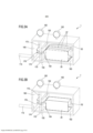
[0030] Em um 19° aspecto de acordo com o aspecto anterior, o um ou mais acionadores são configurados para atuar sobre respectivos um ou mais espaçadores configurados para se apoiar em uma porção de contato de uma primeira porção, opcionalmente em que os um ou mais acionadores são configurados para deslocar e/ou girar o respectivo um ou mais espaçadores entre uma primeira configuração e uma segunda configuração em resposta aos sinais de controle correspondentes fornecidos pela unidade de controle. Em um aspecto adicional de acordo com o 19° aspecto, a parede divisória inclui a primeira porção e uma segunda porção, opcionalmente em que a primeira porção inclui uma porção superior com base em uma configuração de uso da estação de evacuação e/ou em que a segunda porção inclui uma porção inferior com base em uma configuração de uso da estação de evacuação.[0030] In a 19th aspect according to the previous aspect, the one or more actuators are configured to act on respective one or more spacers configured to rest on a contact portion of a first portion, optionally in which the one or more further actuators are configured to shift and/or rotate the respective one or more spacers between a first configuration and a second configuration in response to corresponding control signals provided by the control unit. In a further aspect according to the 19th aspect, the dividing wall includes the first portion and a second portion, optionally wherein the first portion includes an upper portion based on an evacuation station usage configuration and/or wherein the second portion includes a bottom portion based on an evacuation station usage configuration.
[0031] Em um 20° aspecto de acordo com o aspecto anterior, a primeira configuração inclui um respectivo espaçador que está em uma posição retraída e a segunda configuração inclui o respectivo espaçador que está em uma posição estendida, opcionalmente em que uma superfície de apoio do respectivo espaçador está configurada para sobressair da segunda porção e se apoiar na porção de contato na segunda configuração e/ou em que a superfície de apoio do respectivo espaçador está configurada para não sobressair da segunda porção na primeira configuração.[0031] In a 20th aspect according to the previous aspect, the first configuration includes a respective spacer that is in a retracted position and the second configuration includes the respective spacer that is in an extended position, optionally in which a support surface of the respective spacer is configured to protrude from the second portion and rest on the contact portion in the second embodiment and/or where the bearing surface of the respective spacer is configured not to protrude from the second portion in the first embodiment.
[0032] Em um 21° aspecto de acordo com o 15° aspecto ou de acordo com qualquer um dos aspectos anteriores em combinação com o 15° aspecto, a unidade de controle está conectada a uma válvula de admissão, a válvula de admissão estando posicionada sobre uma linha de entrada configurada para colocar a primeira câmara em comunicação fluídica com uma atmosfera ambiente ou com uma fonte de ar pressurizado e em que a unidade de controle é configurada para fornecer à primeira câmara um aumento na primeira pressão interna ao controlar a válvula de admissão, opcionalmente o aumento na pressão variando de cerca de 5 mbar a cerca de 100 mbar, de preferência cerca de 5 mbar a cerca de 50 mbar.[0032] In a 21st aspect in accordance with the 15th aspect or in accordance with any of the preceding aspects in combination with the 15th aspect, the control unit is connected to an inlet valve, the inlet valve being positioned over an inlet line configured to place the first chamber in fluid communication with an ambient atmosphere or a source of pressurized air and wherein the control unit is configured to provide the first chamber with an increase in the first internal pressure by controlling the inlet valve. intake, optionally increasing in pressure ranging from about 5 mbar to about 100 mbar, preferably about 5 mbar to about 50 mbar.
[0033] Em um 22° aspecto de acordo com qualquer um dos aspectos anteriores, a unidade de controle é configurada para controlar o diferencial de pressão de acordo com um perfil de pressão predeterminado que inclui uma pluralidade de valores de pressão ao longo do tempo, em que o perfil de pressão é selecionado de modo a aspirar o gás da segunda câmara e de dentro do pacote através da fenda.[0033] In a 22nd aspect according to any one of the preceding aspects, the control unit is configured to control the pressure differential according to a predetermined pressure profile that includes a plurality of pressure values over time, wherein the pressure profile is selected so as to draw gas from the second chamber and from within the package through the slit.
[0034] Em um 23° aspecto de acordo com o aspecto anterior, o perfil de pressão inclui um valor inicial de pressão, opcionalmente o valor inicial de pressão é igual a cerca da pressão ambiente e/ou o perfil de pressão inclui um valor final de pressão, opcionalmente o valor final de pressão sendo menor do que o valor inicial de pressão, opcionalmente o valor final de pressão sendo cerca de 20 mbar ou menos, de preferência cerca de 10 mbar ou menos, mais preferivelmente cerca de 5 mbar ou menos.[0034] In a 23rd aspect according to the previous aspect, the pressure profile includes an initial pressure value, optionally the initial pressure value is equal to about ambient pressure, and/or the pressure profile includes an final value of pressure, optionally the final pressure value being less than the initial pressure value, optionally the final pressure value being about 20 mbar or less, preferably about 10 mbar or less, more preferably about 5 mbar or less .
[0035] Em um 24° aspecto de acordo com qualquer um dos aspectos anteriores, a vedação do pacote compreende criar uma vedação no pacote na extremidade aberta, deste modo, formando um pacote vedado que contém o produto e que tem uma extremidade vedada; opcionalmente, a etapa de criar a vedação no pacote sendo executada quando a aspiração de gás de dentro do pacote e de gás da primeira câmara através da fenda foi substancialmente concluída.[0035] In a 24th aspect according to any one of the preceding aspects, sealing the package comprises creating a seal in the package at the open end, thereby forming a sealed package containing the product and having a sealed end; optionally, the step of creating the seal in the package being performed when the aspiration of gas from within the package and gas from the first chamber through the slit has been substantially completed.
[0036] Em um 25° aspecto de acordo com de qualquer um dos aspectos anteriores, a etapa de fornecer o pacote compreende posicionar um filme tubular em torno do produto a ser empacotado e criar, em uma estação de vedação, uma primeira vedação sobre o filme tubular, deste modo, formando um pacote que contém o produto a ser empacotado e, opcionalmente, criar uma vedação longitudinal ao longo do filme para obter o filme tubular.[0036] In a 25th aspect according to any of the preceding aspects, the step of providing the package comprises positioning a tubular film around the product to be packaged and creating, at a sealing station, a first seal on the tubular film, in this way, forming a package that contains the product to be packaged and, optionally, creating a longitudinal seal along the film to obtain the tubular film.
[0037] Em um 26° aspecto de acordo com o aspecto anterior, o processo compreende ainda, antes da etapa de vedação do pacote, a etapa de lavagem do interior do pacote com gás ou uma mistura de gases; opcionalmente, em que o gás ou mistura de gases compreende um gás inerte; ainda opcionalmente em que o gás consiste substancialmente em ou compreende CO2.[0037] In a 26th aspect according to the previous aspect, the process further comprises, before the step of sealing the package, the step of washing the inside of the package with gas or a mixture of gases; optionally, wherein the gas or gas mixture comprises an inert gas; further optionally wherein the gas substantially consists of or comprises CO2.
[0038] Em um 27° aspecto de acordo com qualquer um dos aspectos anteriores, o processo compreende ainda fornecer à fenda um tamanho de 8 a 20 vezes a espessura do filme; ou fornecer à fenda um tamanho de 2,0 mm ou menos, de preferência 1,5 mm ou menos, mais preferivelmente 1,0 mm ou menos, ainda mais preferivelmente 0,5 mm ou menos; ou fornecer à fenda um tamanho entre 0,2 mm e 2,0 mm, de preferência entre 0,3 mm e 1,5 mm, mais preferivelmente entre 0,4 mm e 1,0 mm, ainda mais preferivelmente entre 0,4 mm e 0,5 mm.[0038] In a 27th aspect according to any one of the preceding aspects, the method further comprises providing the slit with a size of 8 to 20 times the thickness of the film; or providing the slit with a size of 2.0 mm or less, preferably 1.5 mm or less, more preferably 1.0 mm or less, even more preferably 0.5 mm or less; or providing the slit with a size between 0.2 mm and 2.0 mm, preferably between 0.3 mm and 1.5 mm, more preferably between 0.4 mm and 1.0 mm, even more preferably between 0.4 mm and 0.5 mm.
[0039] Em um 28° aspecto de acordo com qualquer um dos aspectos anteriores, o processo compreende ainda fornecer ao interior do filme e/ou do pacote um gás protetor, opcionalmente, o gás protetor compreendendo substancialmente de CO2.[0039] In a 28th aspect according to any one of the foregoing aspects, the process further comprises providing the interior of the film and/or the package with a protective gas, optionally, the protective gas substantially comprising CO2.
[0040] Em um aspecto adicional de acordo com qualquer um dos aspectos anteriores, o processo compreende ainda a etapa de controlar, pela unidade de controle, a fonte de vácuo para fornecer à segunda câmara uma pressão de vácuo controlada.[0040] In a further aspect according to any one of the foregoing aspects, the process further comprises the step of controlling, by the control unit, the vacuum source to provide the second chamber with a controlled vacuum pressure.
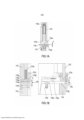
[0041] Em um 29° aspecto, é fornecido um dispositivo para a evacuação de gás de um pacote, em um equipamento de empacotamento, o dispositivo compreendendo uma primeira câmara, uma segunda câmara; e uma parede divisória que separa a primeira câmara da segunda câmara e que tem uma fenda que conecta de modo fluídico as primeira e segunda câmaras, a fenda tendo um tamanho; em que o dispositivo está configurado para receber um pacote que contém um produto a ser empacotado, o pacote sendo feito de um filme e tendo uma extremidade aberta, a extremidade aberta tendo uma porção terminal, uma porção não terminal e uma porção intermediária localizada entre a porção terminal e a porção não terminal da extremidade aberta, o dispositivo sendo configurado para receber o pacote de modo que uma parte terminal da extremidade aberta esteja posicionada dentro da segunda câmara, uma porção não terminal da extremidade aberta e o produto estejam posicionados dentro da primeira câmara e uma porção intermediária da extremidade aberta passe através da fenda, a porção intermediária se estendendo entre a porção terminal e a porção não terminal da extremidade aberta, a extremidade aberta colocando um volume interno do pacote em comunicação fluídica com um volume interno da segunda câmara; o dispositivo compreendendo ainda uma fonte de vácuo conectada de modo fluídico à segunda câmara e configurada para aplicar uma pressão de vácuo controlada à segunda câmara; uma unidade de controle configurada para controlar a fonte de vácuo, a unidade de controle sendo configurada para executar a etapa de controlar um diferencial de pressão entre uma primeira pressão interna na primeira câmara e uma segunda pressão interna na segunda câmara, o diferencial de pressão sendo controlado para provocar a aspiração de gás do volume interno do pacote.[0041] In a 29th aspect, there is provided a device for evacuating gas from a package, in a packaging equipment, the device comprising a first chamber, a second chamber; and a dividing wall separating the first chamber from the second chamber and having a slit fluidly connecting the first and second chambers, the slit having a size; wherein the device is configured to receive a package containing a product to be packaged, the package being made of a film and having an open end, the open end having a terminal portion, a non-terminal portion and an intermediate portion located between the terminal portion and the non-terminal portion of the open end, the device being configured to receive the package such that a terminal portion of the open end is positioned within the second chamber, a non-terminal portion of the open end and the product are positioned within the first chamber and an intermediate portion of the open end passes through the slit, the intermediate portion extending between the terminal portion and the non-terminal portion of the open end, the open end placing an internal volume of the package in fluid communication with an internal volume of the second chamber ; the device further comprising a vacuum source fluidly connected to the second chamber and configured to apply a controlled vacuum pressure to the second chamber; a control unit configured to control the vacuum source, the control unit being configured to perform the step of controlling a pressure differential between a first internal pressure in the first chamber and a second internal pressure in the second chamber, the pressure differential being controlled to cause aspiration of gas from the internal volume of the package.
[0042] Em um 30° aspecto de acordo com o aspecto anterior, a unidade de controle está ainda configurada para receber os respectivos sinais a partir dos primeiro e segundo sensores de pressão indicativos das respectivas primeira e segunda pressões internas nas primeira e segunda câmaras; e controlar o diferencial de pressão com base nas primeira e segunda pressões internas nas primeira e segunda câmaras.[0042] In a 30th aspect according to the previous aspect, the control unit is further configured to receive the respective signals from the first and second pressure sensors indicative of the respective first and second internal pressures in the first and second chambers; and controlling the pressure differential based on the first and second internal pressures in the first and second chambers.
[0043] Em um 31° aspecto de acordo com qualquer um dos 29° a 30° aspectos, a etapa de controlar o diferencial de pressão compreende aumentar o diferencial de pressão, a etapa para aumentar o diferencial de pressão incluindo um ou mais de controlar a fonte de vácuo para diminuir um valor de pressão absoluta da pressão de vácuo controlada aplicada à segunda câmara; e diminuir o tamanho da fenda.[0043] In a 31st aspect according to any one of the 29th to 30th aspects, the step of controlling the pressure differential comprises increasing the pressure differential, the step of increasing the pressure differential including one or more of controlling the vacuum source for decreasing an absolute pressure value of the controlled vacuum pressure applied to the second chamber; and decrease the size of the slit.
[0044] Em um 32° aspecto de acordo com qualquer um dos 29° a 31° aspectos, a etapa de controlar o diferencial de pressão compreende diminuir o diferencial de pressão, a etapa para diminuir o diferencial de pressão incluindo um ou mais de controlar a fonte de vácuo para manter ou aumentar um valor de pressão absoluta da pressão de vácuo controlada aplicada à segunda câmara; e aumentar o tamanho da fenda.[0044] In a 32nd aspect according to any one of the 29th to 31st aspects, the step of controlling the pressure differential comprises decreasing the pressure differential, the step of decreasing the pressure differential including one or more of controlling the vacuum source for maintaining or increasing an absolute pressure value of the controlled vacuum pressure applied to the second chamber; and increase the size of the slit.
[0045] Em um 33° aspecto de acordo com qualquer um dos 29° a 32° aspectos, controlar o diferencial de pressão compreende um ou mais de aumentar o diferencial de pressão durante uma primeira fase de evacuação; e diminuir o diferencial de pressão durante uma segunda fase de evacuação.[0045] In a 33rd aspect according to any one of the 29th to 32nd aspects, controlling the pressure differential comprises one or more of increasing the pressure differential during a first phase of evacuation; and decreasing the pressure differential during a second evacuation phase.
[0046] Em um 34° aspecto de acordo com o aspecto anterior, a primeira fase de evacuação precede a segunda fase de evacuação; e/ou um final da primeira fase de evacuação é determinado quando o diferencial de pressão atinge um valor máximo predeterminado; e/ou controlar o diferencial de pressão compreende manter substancialmente um valor atual do diferencial de pressão durante uma fase de evacuação intermediária, a fase de evacuação intermediária após a primeira fase de evacuação e precedendo a segunda fase de evacuação.[0046] In a 34th aspect in accordance with the previous aspect, the first phase of evacuation precedes the second phase of evacuation; and/or an end of the first evacuation phase is determined when the pressure differential reaches a predetermined maximum value; and/or controlling the pressure differential comprises substantially maintaining a current value of the pressure differential during an intermediate evacuation phase, the intermediate evacuation phase following the first evacuation phase and preceding the second evacuation phase.
[0047] Em um 35° aspecto de acordo com qualquer um dos 29° a 34° aspectos, controlar a pressão diferencial compreende uma pluralidade de etapas para aumentar e/ou diminuir o diferencial de pressão.[0047] In a 35th aspect according to any one of the 29th to 34th aspects, controlling the differential pressure comprises a plurality of steps to increase and/or decrease the pressure differential.
[0048] Em um 36° aspecto de acordo com qualquer um dos 29° a 35° aspectos, controlar o diferencial de pressão compreende fornecer à fenda um primeiro tamanho durante uma fase inicial de evacuação; fornecer à fenda um segundo tamanho durante uma fase transitória de evacuação; e fornecer à fenda um terceiro tamanho durante uma fase final de evacuação; em que a fase inicial de evacuação, a fase transitória de evacuação e a fase final de evacuação são executadas em sequência, o segundo tamanho sendo menor do que os primeiro e terceiro tamanhos.[0048] In a 36th aspect according to any one of the 29th to 35th aspects, controlling the pressure differential comprises providing the crack with a first size during an initial phase of evacuation; providing the crack with a second size during a transient evacuation phase; and providing the slit with a third size during a final evacuation phase; wherein the initial evacuation phase, the transient evacuation phase and the final evacuation phase are performed in sequence, the second size being smaller than the first and third sizes.
[0049] Em um 37° aspecto de acordo com qualquer um dos 29° a 36° aspectos, a fenda é dotada de um formato alongado, opcionalmente a fenda alongada se estendendo de modo substancialmente paralelo a um plano inferior da primeira câmara configurada para receber um pacote posicionado na estação de evacuação.[0049] In a 37th aspect according to any one of the 29th to 36th aspects, the slit is provided with an elongated shape, optionally the elongated slit extending substantially parallel to a bottom plane of the first chamber configured to receive a package positioned at the evacuation station.
[0050] Em um 38° aspecto de acordo com qualquer um dos 29° a 37° aspectos, a unidade de controle é ainda configurada para controlar o diferencial de pressão de forma a não exceder um valor absoluto de cerca de 300 mbar, de preferência cerca de 250 mbar, mais preferivelmente cerca de 200 mbar.[0050] In a 38th aspect according to any one of the 29th to 37th aspects, the control unit is further configured to control the pressure differential so as not to exceed an absolute value of about 300 mbar, preferably about 250 mbar, more preferably about 200 mbar.
[0051] Em um 39° aspecto de acordo com qualquer um dos 29° a 38° aspectos, a primeira câmara está configurada para abrir e fechar e em que a primeira câmara está ainda configurada para permitir que a extremidade aberta do pacote seja introduzida na fenda ao longo de um comprimento da fenda e o pacote seja posicionado dentro da primeira câmara, de modo que a porção terminal da extremidade aberta esteja posicionada dentro da segunda câmara, a porção não terminal da extremidade aberta e o produto estejam posicionados dentro da primeira câmara e a porção intermediária da extremidade aberta passe através da fenda.[0051] In a 39th aspect according to any one of the 29th to 38th aspects, the first chamber is configured to open and close and wherein the first chamber is further configured to allow the open end of the package to be introduced into the slit along a length of the slit and the package is positioned within the first chamber such that the terminal portion of the open end is positioned within the second chamber, the non-terminal portion of the open end and the product are positioned within the first chamber and the middle portion of the open end passes through the slit.
[0052] Em um 40° aspecto de acordo com qualquer um dos 29° a 39° aspectos, a primeira câmara, a segunda câmara e a fenda são configuradas para abrir e fechar e em que a primeira câmara, a segunda câmara e a fenda são ainda configuradas para permitir que a porção terminal da extremidade aberta seja posicionada dentro da segunda câmara; a porção não terminal da extremidade aberta e o pacote sendo posicionados dentro da primeira câmara; e a porção intermediária da extremidade aberta sendo posicionada em sobreposição com a fenda aberta.[0052] In a 40th aspect according to any one of the 29th to 39th aspects, the first chamber, the second chamber and the slit are configured to open and close and in which the first chamber, the second chamber and the slit are further configured to allow the terminal portion of the open end to be positioned within the second chamber; the non-terminal portion of the open end and the package being positioned within the first chamber; and the intermediate portion of the open end being positioned in overlap with the open slit.
[0053] Em um 41° aspecto de acordo com qualquer um dos 29° a 40° aspectos, a unidade de controle é configurada para determinar uma condição de aspiração do pacote e controlar a vedação do pacote, opcionalmente a etapa de determinar a condição de aspiração do pacote precedendo a etapa de vedação do pacote.[0053] In a 41st aspect according to any one of the 29th to 40th aspects, the control unit is configured to determine a condition of aspiration of the package and control the sealing of the package, optionally the step of determining the condition of aspiration of the package preceding the step of sealing the package.
[0054] Em um 42° aspecto de acordo com o 41° aspecto, a unidade de controle está ainda configurada para determinar a condição de aspiração quando a primeira pressão interna é menor do que ou igual a um valor alvo predeterminado, opcionalmente o valor alvo predeterminado sendo cerca de 20 mbar ou menos, de preferência cerca de 10 mbar ou menos, mais preferivelmente cerca de 5 mbar ou menos.[0054] In a 42nd aspect according to the 41st aspect, the control unit is further configured to determine the aspiration condition when the first internal pressure is less than or equal to a predetermined target value, optionally the target value predetermined being about 20 mbar or less, preferably about 10 mbar or less, more preferably about 5 mbar or less.
[0055] Em um 43° aspecto de acordo com qualquer um dos 41° a 42° aspectos, a unidade de controle está ainda configurada para determinar uma condição de aspiração do pacote; e determinar a condição de formação de vácuo quando a condição de formação de vapor do pacote é determinada.[0055] In a 43rd aspect according to any one of the 41st to 42nd aspects, the control unit is further configured to determine a package aspiration condition; and determining the vacuum build-up condition when the steam build-up condition of the package is determined.
[0056] Em um 44° aspecto de acordo com o aspecto anterior, a unidade de controle está ainda configurada para determinar a condição de formação de vapor quando, durante a etapa de controlar o diferencial de pressão, o volume interno do pacote aumenta para um período de tempo de 50 ms ou mais, de preferência 100 ms ou mais, mais preferivelmente 200 ms ou mais, ou o volume interno do pacote aumenta em uma quantidade de 2 % ou mais, de preferência em uma quantidade de 3 % ou mais, mais preferivelmente em uma quantidade de 5 % ou mais, a quantidade sendo medida como uma percentagem do volume interno do pacote com base na primeira pressão interna.[0056] In a 44th aspect according to the previous aspect, the control unit is further configured to determine the steam formation condition when, during the step of controlling the pressure differential, the internal volume of the package increases to a time period of 50ms or more, preferably 100ms or more, more preferably 200ms or more, or the internal volume of the packet increases by an amount of 2% or more, preferably by an amount of 3% or more, more preferably in an amount of 5% or more, the amount being measured as a percentage of the internal volume of the package based on the first internal pressure.
[0057] Em um 45° aspecto de acordo com qualquer um dos dois aspectos anteriores, a unidade de controle é ainda conectada a um terceiro sensor configurado para emitir um sinal de distância de controle indicativo de uma distância de controle entre o terceiro sensor e uma porção do filme e em que a unidade de controle é adicionalmente configurada para determinar a condição de formação de vapor quando, durante a etapa de controlar o diferencial de pressão, a distância de controle diminui em uma quantidade de 2 % ou mais, de preferência em uma quantidade de 3 % ou mais, mais preferivelmente em uma quantidade de 5 % ou mais em relação a uma distância máxima de controle atual, a distância máxima de controle atual sendo determinada com base no sinal da distância de controle; opcionalmente, em que o terceiro sensor inclui um sensor eletromagnético, de preferência em que o terceiro sensor inclui um sensor óptico ou um sensor ultrassônico.[0057] In a 45th aspect according to either of the two preceding aspects, the control unit is further connected to a third sensor configured to emit a control distance signal indicative of a control distance between the third sensor and a portion of the film and wherein the control unit is further configured to determine the vapor formation condition when, during the step of controlling the pressure differential, the control distance decreases by an amount of 2% or more, preferably by an amount of 3% or more, more preferably in an amount of 5% or more relative to a current maximum control distance, the current maximum control distance being determined based on the sign of the control distance; optionally, wherein the third sensor includes an electromagnetic sensor, preferably wherein the third sensor includes an optical sensor or an ultrasonic sensor.
[0058] Em um 46° aspecto de acordo com qualquer um dos 29° a 45° aspectos, a unidade de controle está ainda conectada a um ou mais acionadores configurados para fornecer à fenda pelo menos um primeiro tamanho e um segundo tamanho em resposta a sinais de controle correspondentes fornecidos pela unidade de controle, o primeiro tamanho e o segundo tamanho sendo diferentes um do outro.[0058] In a 46th aspect according to any one of the 29th to 45th aspects, the control unit is further connected to one or more drivers configured to provide the slit with at least a first size and a second size in response to corresponding control signals provided by the control unit, the first size and the second size being different from each other.
[0059] Em um 47° aspecto de acordo com qualquer um dos 29° a 46° aspectos, o um ou mais acionadores são configurados para atuar de acordo com respectivo um ou mais espaçadores configurados para se apoiar em uma porção de contato de uma primeira porção, opcionalmente em que o um ou mais os acionadores são configurados para deslocar e/ou girar o respectivo um ou mais espaçadores entre uma primeira configuração e uma segunda configuração em resposta aos sinais de controle correspondentes fornecidos pela unidade de controle. Em um aspecto adicional de acordo com o 47° aspecto, a parede divisória inclui uma primeira porção e uma segunda porção, opcionalmente em que a primeira porção inclui uma porção superior com base em uma configuração de uso da estação de evacuação e/ou em que a segunda porção inclui uma porção inferior com base em uma configuração de uso da estação de evacuação.[0059] In a 47th aspect according to any one of the 29th to 46th aspects, the one or more actuators are configured to act in accordance with the respective one or more spacers configured to rest on a contact portion of a first portion, optionally wherein the one or more actuators are configured to shift and/or rotate the respective one or more spacers between a first configuration and a second configuration in response to corresponding control signals provided by the control unit. In a further aspect according to the 47th aspect, the dividing wall includes a first portion and a second portion, optionally wherein the first portion includes an upper portion based on an evacuation station usage configuration and/or wherein the second portion includes a bottom portion based on an evacuation station usage configuration.
[0060] Em um 48° aspecto de acordo com qualquer um dos 29° a 47° aspectos, a primeira configuração inclui um respectivo espaçador que está em uma posição retraída e a segunda configuração inclui o respectivo espaçador que está em uma posição estendida, opcionalmente em que uma superfície de apoio do respectivo espaçador é configurada para sobressair da segunda porção e se apoiar na porção de contato na segunda configuração e/ou em que a superfície de apoio do respectivo espaçador é configurada para não sobressair da segunda porção na primeira configuração.[0060] In a 48th aspect according to any one of the 29th to 47th aspects, the first configuration includes a respective spacer that is in a retracted position and the second configuration includes the respective spacer that is in an optionally extended position wherein a bearing surface of the respective spacer is configured to protrude from the second portion and rest on the contact portion in the second embodiment and/or wherein the bearing surface of the respective spacer is configured not to protrude from the second portion in the first embodiment.
[0061] Em um 49° aspecto de acordo com o 43° aspecto ou de acordo com qualquer um dos 29° a 48° aspectos em combinação com o 43° aspecto, a unidade de controle está conectada a uma válvula de admissão, a válvula de admissão estando posicionada sobre uma linha de entrada configurada para colocar a primeira câmara em comunicação fluídica com uma atmosfera ambiente ou com uma fonte de ar pressurizado e em que a unidade de controle é configurada para fornecer à primeira câmara um aumento na primeira pressão interna ao controlar a válvula de admissão, opcionalmente o aumento da pressão variando entre cerca de 5 mbar e cerca de 100 mbar, de preferência entre cerca de 5 mbar e cerca de 50 mbar.[0061] In a 49th aspect in accordance with the 43rd aspect or in accordance with any of the 29th to 48th aspects in combination with the 43rd aspect, the control unit is connected to an intake valve, the valve inlet being positioned over an inlet line configured to place the first chamber in fluid communication with an ambient atmosphere or a source of pressurized air and wherein the control unit is configured to provide the first chamber with an increase in the first internal pressure to the controlling the inlet valve, optionally increasing the pressure ranging between about 5 mbar and about 100 mbar, preferably between about 5 mbar and about 50 mbar.
[0062] Em um 50° aspecto de acordo com qualquer um dos 29° a 49° aspectos, a unidade de controle é configurada para controlar o diferencial de pressão de acordo com um perfil de pressão predeterminado, incluindo uma pluralidade de valores de pressão ao longo do tempo, em que o perfil de pressão é selecionado de modo a aspirar o gás da segunda câmara e de dentro do pacote através da fenda.[0062] In a 50th aspect according to any one of the 29th to 49th aspects, the control unit is configured to control the pressure differential according to a predetermined pressure profile, including a plurality of pressure values at the over time, in which the pressure profile is selected in order to draw the gas from the second chamber and inside the package through the slit.
[0063] Em um 51° aspecto de acordo com qualquer um dos 29° a 50° aspectos, o perfil de pressão inclui um valor inicial de pressão, opcionalmente o valor inicial de pressão sendo igual a cerca da pressão ambiente e/ou o perfil de pressão inclui um valor final de pressão, opcionalmente o valor final de pressão sendo menor do que o valor inicial de pressão, opcionalmente o valor final de pressão sendo cerca de 20 mbar ou menos, de preferência cerca de 10 mbar ou menos, mais preferivelmente cerca de 5 mbar ou menos.[0063] In a 51st aspect according to any one of the 29th to 50th aspects, the pressure profile includes an initial pressure value, optionally the initial pressure value being equal to about ambient pressure and/or the profile of pressure includes a final pressure value, optionally the final pressure value being less than the initial pressure value, optionally the final pressure value being about 20 mbar or less, preferably about 10 mbar or less, most preferably about 5 mbar or less.
[0064] Em um 52° aspecto de acordo com qualquer um dos 29° a 51° aspectos, o dispositivo compreende ainda um dispositivo de vedação configurado para vedar o pacote, o dispositivo de vedação sendo configurado para criar uma vedação no pacote na extremidade aberta, deste modo, formando um pacote vedado que contém o produto e que tem uma extremidade vedada; opcionalmente, a etapa de criar a vedação no pacote sendo executada quando a aspiração de gás de dentro do pacote e do gás da primeira câmara através da fenda foi substancialmente concluída.[0064] In a 52nd aspect according to any one of the 29th to 51st aspects, the device further comprises a sealing device configured to seal the pack, the sealing device being configured to create a seal on the pack at the open end thereby forming a sealed package containing the product and having a sealed end; optionally, the step of creating the seal in the package being performed when the aspiration of gas from within the package and gas from the first chamber through the slit has been substantially completed.
[0065] Em um 53° aspecto de acordo com qualquer um dos 29° a 52° aspectos, a fenda é dotada de um tamanho de 8 a 20 vezes a espessura do filme; ou a fenda é dotada de um tamanho de 2,0 mm ou menos, de preferência 1,5 mm ou menos, mais preferivelmente 1,0 mm ou menos, ainda mais preferivelmente 0,5 mm ou menos; ou a fenda é dotada de um tamanho entre 0,2 mm e 2,0 mm, de preferência entre 0,3 mm e 1,5 mm, mais preferivelmente entre 0,4 mm e 1,0 mm, ainda mais preferivelmente entre 0,4 mm e 0,5 mm.[0065] In a 53rd aspect according to any one of the 29th to 52nd aspects, the slit is endowed with a size of 8 to 20 times the thickness of the film; or the slit is provided with a size of 2.0 mm or less, preferably 1.5 mm or less, more preferably 1.0 mm or less, even more preferably 0.5 mm or less; or the slit is provided with a size between 0.2 mm and 2.0 mm, preferably between 0.3 mm and 1.5 mm, more preferably between 0.4 mm and 1.0 mm, even more preferably between 0 .4 mm and 0.5 mm.
[0066] Em um 54° aspecto de acordo com qualquer um dos 29° a 53° aspectos, um gás protetor é fornecido ao interior do filme e/ou do pacote, opcionalmente o gás protetor compreende substancialmente CO2.[0066] In a 54th aspect according to any one of the 29th to 53rd aspects, a shielding gas is supplied to the interior of the film and/or the package, optionally the shielding gas substantially comprises CO2.
[0067] Em um 55° aspecto de acordo com qualquer um dos 29° a 54° aspectos, a unidade de controle está programada para controlar o meio de evacuação para criar uma pressão de vácuo interna compreendida entre 1 mbar e 20 mbar, de preferência entre 3 mbar e 10 mbar, mais preferivelmente cerca de 5 mbar.[0067] In a 55th aspect according to any one of the 29th to 54th aspects, the control unit is programmed to control the evacuation means to create an internal vacuum pressure comprised between 1 mbar and 20 mbar, preferably between 3 mbar and 10 mbar, more preferably about 5 mbar.
[0068] Em um 56° aspecto de acordo com qualquer um dos 29° a 55° aspectos, a unidade de controle está ainda configurada para controlar a fonte de vácuo para fornecer à segunda câmara uma pressão de vácuo controlada.[0068] In a 56th aspect according to any one of the 29th to 55th aspects, the control unit is further configured to control the vacuum source to provide the second chamber with a controlled vacuum pressure.
[0069] Em um 57° aspecto, é fornecido um equipamento de empacotamento que compreende uma estação de evacuação acoplada à unidade de controle e uma estação de saída; em que a estação de evacuação compreende um dispositivo para evacuação de acordo com qualquer um dos 29° a 56° aspectos.[0069] In a 57th aspect, packaging equipment is provided comprising an evacuation station coupled to the control unit and an output station; wherein the evacuation station comprises an evacuation device according to any one of the 29th to 56th aspects.
[0070] Em um 58° aspecto de acordo com o aspecto anterior, o dispositivo compreende ainda um dispositivo de descarga configurado para descarregar, antes de vedar o pacote, um gás ou uma mistura de gases no interior do pacote; opcionalmente, em que o gás ou mistura de gases compreende um gás inerte; além disso, opcionalmente, em que o gás consiste substancialmente em ou compreende CO2.As vantagens do processo de empacotamento e do equipamento de empacotamento incluem o fato de que a evacuação de gás/ar de um pacote é executada de uma maneira eficaz e eficiente.[0070] In a 58th aspect according to the previous aspect, the device further comprises a discharge device configured to discharge, before sealing the package, a gas or a mixture of gases inside the package; optionally, wherein the gas or gas mixture comprises an inert gas; further, optionally, wherein the gas substantially consists of or comprises CO 2 . The advantages of the packaging process and the packaging equipment include the fact that the evacuation of gas/air from a package is carried out in an effective and efficient manner.
[0071] As vantagens do processo de empacotamento e do equipamento de empacotamento incluem ainda o fato de que a evacuação de gás/ar de um pacote é executada de forma eficiente, minimizando ou eliminando a evaporação de fluidos do produto e/ou de dentro do pacote e/ou minimizando ou eliminando a evacuação do fluido evaporado. O acima também é dito como minimizando ou eliminando o vapor e seus efeitos.[0071] The advantages of the packaging process and packaging equipment also include the fact that the gas/air evacuation of a package is performed efficiently, minimizing or eliminating the evaporation of fluids from the product and/or from within the package and/or minimizing or eliminating evacuation of evaporated fluid. The above is also said to minimize or eliminate steam and its effects.
[0072] As vantagens do processo de empacotamento e do equipamento de empacotamento incluem ainda o fato de que o processo de evacuação pode ser modificado para se adaptar a uma grande variedade de propriedades de produto e/ou pacotes, por exemplo, tipo de produto, consistência, tamanho, formato, etc. e tipo de pacote, tamanho, formato, material, etc. Em particular, o processo de evacuação pode ser modificado de modo a controlar a taxa de evacuação durante diferentes estágios de evacuação, especialmente nos estágios finais durante os quais a formação de vapor pode ocorrer.[0072] The advantages of the packaging process and packaging equipment also include the fact that the evacuation process can be modified to adapt to a wide variety of product and/or package properties, for example, product type, consistency, size, format, etc. and package type, size, shape, material, etc. In particular, the evacuation process can be modified in order to control the evacuation rate during different evacuation stages, especially in the final stages during which steam formation can occur.
[0073] As vantagens do processo de empacotamento e do equipamento de empacotamento também incluem o fato de que um diferencial de pressão entre uma primeira e uma segunda câmaras pode ser controlado de modo a evacuar de forma eficaz e/ou eficiente um pacote. O controle do diferencial de pressão pode incluir aumento e/ou diminuição do diferencial de pressão uma ou mais vezes durante a evacuação.[0073] The advantages of the packaging process and packaging equipment also include the fact that a pressure differential between a first and a second chamber can be controlled in order to effectively and/or efficiently evacuate a package. Pressure differential control may include increasing and/or decreasing the pressure differential one or more times during evacuation.
[0074] As vantagens do processo de empacotamento e do equipamento de empacotamento incluem ainda o fato de que o risco de deterioração dos produtos (por exemplo, formação de mofo causada por oxigênio residual) pode ser reduzido ou eliminado ao fornecer aos pacotes um gás protetor antes da evacuação do gás ou ar.[0074] The advantages of the packaging process and packaging equipment further include the fact that the risk of spoilage of products (for example, mold formation caused by residual oxygen) can be reduced or eliminated by supplying packages with a protective gas before the evacuation of gas or air.
[0075] O processo de empacotamento também pode facilitar a integração completa e automação com um dispositivo horizontal de formação, envasamento e vedação (HFFS).[0075] The packaging process can also facilitate complete integration and automation with a horizontal form, fill and seal (HFFS) device.
[0076] A Figura 1 mostra uma vista esquemática seccional transversal de uma primeira modalidade de uma estação de evacuação de um equipamento de empacotamento de acordo com a presente invenção, o pacote sendo mostrado em um estado antes da evacuação;[0076] Figure 1 shows a schematic cross-sectional view of a first embodiment of an evacuation station of a packaging equipment according to the present invention, the package being shown in a state before evacuation;
[0077] a Figura 1A mostra uma primeira modalidade de um mecanismo de fenda ajustável de acordo com modalidades da presente invenção;[0077] Figure 1A shows a first embodiment of an adjustable slit mechanism in accordance with embodiments of the present invention;
[0078] a Figura 1B mostra uma segunda modalidade de um mecanismo de fenda ajustável de acordo com modalidades da presente invenção;[0078] Figure 1B shows a second embodiment of an adjustable slit mechanism in accordance with embodiments of the present invention;
[0079] a Figura 1C mostra uma terceira modalidade de um mecanismo de fenda ajustável de acordo com modalidades da presente invenção;[0079] Figure 1C shows a third embodiment of an adjustable slit mechanism in accordance with embodiments of the present invention;
[0080] a Figura 1D mostra uma quarta modalidade de um mecanismo de fenda ajustável de acordo com modalidades da presente invenção;[0080] Figure 1D shows a fourth embodiment of an adjustable slit mechanism in accordance with embodiments of the present invention;
[0081] a Figura 2 mostra uma vista esquemática seccional transversal da primeira modalidade mostrada na Figura 1, o pacote sendo mostrado em um estado durante a evacuação;[0081] Figure 2 shows a schematic cross-sectional view of the first embodiment shown in Figure 1, the package being shown in a state during evacuation;
[0082] a Figura 3A mostra uma vista seccional isométrica da primeira modalidade mostrada nas Figuras 1 e 2, o pacote sendo mostrado em um estado antes de evacuação;[0082] Figure 3A shows an isometric sectional view of the first embodiment shown in Figures 1 and 2, the package being shown in a state prior to evacuation;
[0083] a Figura 3B mostra uma vista seccional transversal isométrica da primeira modalidade mostrada nas Figuras 1 e 2, o pacote sendo mostrado em um estado durante a evacuação;[0083] Figure 3B shows an isometric cross-sectional view of the first embodiment shown in Figures 1 and 2, the package being shown in a state during evacuation;
[0084] a Figura 4 mostra um fluxograma que ilustra um exemplo de processo de evacuação de acordo com a presente invenção;[0084] Figure 4 shows a flowchart illustrating an example of evacuation process according to the present invention;
[0085] a Figura 4A mostra uma vista seccional transversal esquemática da primeira modalidade de uma estação de evacuação de um equipamento de empacotamento de acordo com a presente invenção, o pacote sendo mostrado em um estado onde ocorre evaporação;[0085] Figure 4A shows a schematic cross-sectional view of the first embodiment of an evacuation station of a packaging equipment according to the present invention, the package being shown in a state where evaporation occurs;
[0086] a Figura 4B mostra um fluxograma que ilustra um processo de controle exemplificativo de acordo com a presente invenção;[0086] Figure 4B shows a flowchart illustrating an exemplary control process in accordance with the present invention;
[0087] a Figura 5A mostra um diagrama que ilustra uma curva de controle de vácuo exemplificativa com base na qual a evacuação de acordo com modalidades da presente invenção pode ser controlada; e[0087] Figure 5A shows a diagram illustrating an exemplary vacuum control curve based on which evacuation in accordance with embodiments of the present invention can be controlled; It is
[0088] a Figura 5B mostra um diagrama que ilustra outras curvas de controle de vácuo exemplificativas com base nas quais a evacuação de acordo com modalidades da presente invenção pode ser controlada.[0088] Figure 5B shows a diagram illustrating other exemplary vacuum control curves based on which evacuation in accordance with embodiments of the present invention can be controlled.
[0089] A Figura 1 mostra uma vista esquemática seccional transversal de uma primeira modalidade de uma estação de evacuação de um equipamento de empacotamento de acordo com a presente invenção, o pacote sendo mostrado em um estado antes da evacuação. A estação de evacuação 1 compreende, em geral, uma primeira câmara 160 e uma segunda câmara 180. A primeira câmara 160 está configurada para alojar ou acomodar um pacote 50 que contém um produto 20 a ser empacotado. A segunda câmara 180 está em comunicação fluídica com a primeira câmara 160 através de uma fenda 176. A fenda 176 pode ser uma fenda que tem um tamanho ajustável ou um tamanho fixo, dependendo da modalidade individual. A primeira modalidade descrita nas Figuras 1 e 2 é dotada de uma fenda 176 ajustável. O tamanho da fenda 176 ajustável pode ser ajustado, por exemplo, ao ajustar a altura ou largura da fenda 176, conforme é descrito em maiores detalhes mais abaixo. Observe que os termos "altura" ou "largura" se referem a uma condição de uso da estação de evacuação, constituindo exemplos concretos de como o tamanho de uma fenda 176 pode ser ajustado. Nenhum destes termos se destina a limitar a maneira como o ajuste é fornecido. Deve ser observado ainda que o ajuste do tamanho de uma fenda 176 inclui o ajuste de uma área de uma abertura definida pela fenda 176. Uma fenda alongada 176, por exemplo, conforme mostrado nas Figura 1 e 2 (seção transversal) ou nas Figuras 3A e 3B (vista isométrica) está configurada para permitir a modificação de uma distância entre bordas opostas que delimitam a fenda 176, deste modo, permitindo ajustar o tamanho da fenda 176.[0089] Figure 1 shows a schematic cross-sectional view of a first embodiment of an evacuation station of a packaging equipment according to the present invention, the package being shown in a state before evacuation. The evacuation station 1 generally comprises a
[0090] Uma parede divisória 170 separa as primeira e segunda câmaras uma da outra, exceto quanto à fenda 176. Em geral, a fenda ajustável 176 (ou uma fenda fixa nas modalidades correspondentes) pode ser dotada de uma gaxeta (não mostrada na Figura 1; por exemplo, gaxeta 172g na Figura 1B, conforme descrito abaixo) configurada para permitir um fluxo de fluido controlado na presença de uma diferença de pressão. A gaxeta pode ser configurada para minimizar ou reduzir significativamente a pressão exercida pelas porções 172 e 174 da parede divisória 170 sobre o material de filme que se estende através da fenda. Aqui, a pressão exercida pela gaxeta é configurada para ser suficientemente alta para vedar suficientemente a fenda 176 em relação ao material de empacotamento e de modo a evitar um fluxo excessivo de gás da primeira câmara 160 para a segunda câmara 180, o fluxo de gás sendo externo ao pacote 50. Ao mesmo tempo, a pressão exercida pela gaxeta é configurada para ser suficientemente baixa para permitir um fluxo de gás suficiente do volume interno 58 do pacote 50 através da fenda ajustável (ou fixa) 176.[0090] A dividing
[0091] A primeira câmara 160 é dotada de um sensor de pressão 162 e a segunda câmara 180 é dotada de um sensor de pressão 182. Ambos os sensores de pressão estão conectados a uma unidade de controle 60 e são configurados para fornecer à unidade de controle 60 um respectivo sinal de controle indicativo de uma pressão correspondente nas primeira e segunda câmaras, respectivamente. A unidade de controle 60 está configurada para receber os sinais de controle dos sensores e processar os sinais em um processo de evacuação (por exemplo, envolvendo o controle de uma bomba de vácuo 116 para fornecer uma pressão de vácuo e/ou aumentar ou diminuir a pressão de vácuo).[0091] The
[0092] A estação de evacuação compreende ainda uma bomba de vácuo 116 opcionalmente com um propulsor (não mostrado) e uma válvula de controle 112. A bomba de vácuo 116 e a válvula de controle 112 estão conectadas à segunda câmara 180 através de uma linha de vácuo 110 configurada para evacuar a segunda câmara ao colocar a bomba de vácuo 116 e a segunda câmara 180 em comunicação fluídica uma com a outra. A bomba de vácuo 116 e a válvula de controle 112 estão conectadas à unidade de controle 60 e são configuradas para receber sinais de controle da unidade de controle 60. Isto permite que a unidade de controle 60 controle a bomba de vácuo 116 (por exemplo, ao aumentar/diminuir a potência fornecida à bomba ou enviar um sinal de controle que controla um motor que aciona a bomba em uma velocidade maior ou menor) e/ou a válvula de controle 112 (por exemplo, ao controlar seletivamente a válvula para abrir ou fechar pelo menos parcial ou totalmente a linha 110). A válvula de controle pode ser uma válvula de controle de tipo servo ou qualquer outra válvula de controle configurada para abrir ou fechar, gradual ou proporcionalmente, uma conexão fluídica. A válvula de controle pode incluir componentes configurados para se mover entre uma primeira posição, na qual a conexão fluídica é totalmente aberta (por exemplo, fluxo de fluido totalmente irrestrito; 100 % aberto), uma segunda posição na qual a conexão fluídica é totalmente fechada ou fluxo de fluido bloqueado; 0 % aberto) e uma ou mais posições intermediárias nas quais a conexão fluídica é parcialmente aberta (por exemplo, fluxo de fluido parcialmente restrito; por exemplo, 20 %, 50 % ou 68 % aberto). A unidade de controle 60 está configurada para controlar um ou mais componentes diferentes (por exemplo, bomba 116, válvula 112) com base em um processo de evacuação e dependendo dos sinais recebidos de um ou mais sensores diferentes (por exemplo, sensores 162, 182). Algumas modalidades não exibem uma válvula de controle e/ou um propulsor. Deve ser entendido que componentes e/ou configurações alternativos podem ser usados para fornecer vácuo à estação de evacuação 1.[0092] The evacuation station further comprises a
[0093] A parede divisória é dotada de uma fenda ajustável 176 definida por uma primeira porção (por exemplo, superior) 172 da parede divisória 170 e uma segunda porção (por exemplo, inferior) 174 da parede divisória. Na primeira modalidade, a primeira porção 172 da parede divisória 170 é verticalmente ajustável, deste modo, facilitando o ajuste do tamanho da fenda 176. Para esta finalidade, a primeira porção 172 é dotada de um acionador (não mostrado) configurado para se mover verticalmente (por exemplo, deslocar, estender, retrair) a primeira porção 172. O acionador pode ser conectado à unidade de controle 60 de modo que a unidade de controle 60 controle o acionador de acordo com um processo de evacuação executado pela unidade de controle 60. Deve ser entendido, em outras modalidades, que a fenda 176 pode ser dotada de um tamanho ajustável de formatos alternativos, por exemplo, que envolve ajustar verticalmente a segunda porção 174 (por exemplo, movida, deslocada, estendida, retraída) usando um acionador correspondente. Em ainda outras modalidades, tanto a primeira como a segunda porção podem ser ajustáveis (por exemplo, verticalmente) e/ou ajustes adicionais podem ser implementados, por exemplo, ajuste de altura da fenda 176 na parede divisória 170 ao ajustar tanto a primeira como a segunda porções 172 e 174 da mesma maneira (por exemplo, ao deslocar para cima ou para baixo, estender e/ou retrair). A fenda 176, em geral, um formato alongado que se estende ao longo das primeira e segunda porções 172 e 174 e transversalmente através da primeira câmara 160. Em algumas modalidades (consulte, por exemplo, a Figura 1B) a fenda pode ser dotada de uma gaxeta flexível para vedar a fenda (ajustável ou fixa) até certo ponto (consulte acima). Em ainda outras modalidades, a gaxeta pode ser configurada para expandir ou contrair em virtude de uma pressão interna (por exemplo, pneumática, hidráulica), deste modo, ajustando o aperto da vedação fornecida pela junta.[0093] The divider wall is provided with an
[0094] Pelo menos a primeira câmara 160 está configurada para abrir e fechar de modo a permitir que um pacote 50 (que contém um produto 20 a ser empacotado) seja introduzido na primeira câmara 160 para evacuação e de modo que possa ser removida da primeira câmara 160 após a evacuação. Isto pode ser conseguido ao fornecer à estação de evacuação 1 e/ou à primeira câmara 160 e, opcionalmente à segunda câmara 180, porções superior e inferior (não mostradas explicitamente) configuradas para fornecer à estação de evacuação 1 e/ou à primeira câmara 160 e, opcionalmente à segunda câmara 180, um mecanismo de abertura/fechamento. Deve ser entendido que há outras alternativas (por exemplo, mecanismos de dobradiça, mecanismos de lingueta, etc.) que podem ser empregados aqui.[0094] At least the
[0095] Em algumas modalidades, apenas a primeira câmara 160 está configurada para abrir independentemente da segunda câmara. Nestas modalidades, a segunda câmara pode ser configurada para permanecer fechada e apresentar a fenda 176 como uma fenda alongada na qual a boca do saco de um pacote 50 pode ser introduzida, por exemplo, lateralmente. Para inserir um pacote 50, a primeira câmara 160 é aberta com base em um dos mecanismos mencionados acima. Depois, o pacote 50 é colocado na primeira câmara 160 de uma maneira que permita que a boca do saco do pacote 50 seja introduzida/inserida na fenda 176 apresentada pela segunda câmara (fechada) 180. Finalmente, a primeira câmara 160 fecha novamente e o processo de evacuação pode ser iniciado. Esta modalidade pode implicar em vantagens ao fornecer à boca no lado posterior do saco (por exemplo, uma parte intermediária da extremidade aberta do pacote) pregas durante a inserção da boca no lado posterior do saco na fenda 176. Isto pode ser conseguido ao fornecer rodas/correias lisas ou dentadas configuradas para introduzir a parte intermediária da extremidade aberta do pacote 50 na fenda 176. As pregas fornecidas na boca no lado posterior do saco desta maneira podem facilitar uma evacuação mais eficaz e/ou melhorar substancialmente a aspiração do pacote 50.[0095] In some embodiments, only the
[0096] Em outras modalidades, tanto a primeira como a segunda câmara 160 e 180 são configuradas para abrir e fechar, por exemplo, com base em um mecanismo de articulação configurado para abrir e fechar toda a estação de evacuação 1. Nestas modalidades, a fenda 176 também é configurada para abrir no sentido de que, por exemplo, a primeira porção (superior) 172 da parede divisória 170 pode ser configurada para ser levantada para cima e/ou afastada da segunda porção (por exemplo, inferior) 174 da parede divisória 170, deste modo, permitindo facilidade de colocação do pacote 50 dentro da primeira câmara 160 e da boca do saco do pacote 50 dentro da fenda 176. De modo a inserir um pacote 50, as primeira e segunda câmaras 160 e 180 são abertas com base em um dos mecanismos mencionados acima. Então, o pacote 50 é colocado na primeira câmara 160 e a boca do saco 50 é colocada na proximidade da fenda 176 (por exemplo, acima ou na segunda porção 174 da parede divisória 170). Finalmente, as primeira e segunda câmaras 160 e 180 são novamente fechadas, deste modo, envolvendo a boca do saco 50 dentro da fenda 176 (por exemplo, entre as primeira e segunda porções 172 e 174 da parede divisória 170) e o processo de evacuação pode ser iniciado.[0096] In other embodiments, both the first and
[0097] Observe que a maneira individual pela qual os pacotes 50 são colocados na estação de evacuação 1 e os mecanismos individuais para abrir/fechar a estação de evacuação 1, a primeira câmara 160 e/ou a segunda câmara 180 podem ser selecionados com base na aplicação individual e com base nas propriedades dos pacotes 50 e/ou dos produtos 20.[0097] Note that the individual way in which the
[0098] O pacote 50 é feito a partir de um filme de empacotamento 52 e tem o formato de um saco aberto que tem uma extremidade aberta e uma extremidade fechada. O saco contém o produto 20 e é mostrado na Figura 1 em um estado antes da evacuação, isto é, com o filme de empacotamento 52 não aderente ao produto 20, deste modo, indicando que o gás ou ar residual está presente dentro do pacote 50, por exemplo, em um volume interno 58. O volume interno 58 inclui pelo menos o volume interno do filme de empacotamento 52 e em torno do produto 20, porém, também volumes de gás/ar contidos, fechados ou de outro modo dentro do próprio produto 20 (por exemplo, no caso de um queijo que tem buracos, legumes, tais como brócolis ou couve-flor, uns produtos pouco porosos ou outros produtos que contenham cavidades capazes de alojar gás/ar).[0098] The
[0099] O pacote 50 é posicionado dentro da primeira câmara 160 de maneira tal que a extremidade aberta se estende a partir da primeira câmara 160 através da fenda 176 e na segunda câmara 180. Durante a evacuação, portanto, uma porção externa 54 da extremidade aberta está posicionada na segunda câmara 180, uma porção interna 56 da extremidade aberta está posicionada na primeira câmara e uma porção intermediária 55 da extremidade aberta, localizada entre as porções externa 54 e interna 56 está posicionada na região da fenda 176. O volume interno dentro do pacote 50 é, assim, colocado em comunicação fluídica com o volume interno da segunda câmara 180 pela boca do saco que se estende da primeira câmara 160 através da fenda 176 e para a segunda câmara 180.[0099] The
[00100] Em geral, a unidade de controle 60 é configurada para controlar a bomba de vácuo 116 e/ou a válvula de controle 112 de modo a fornecer à segunda câmara 180 uma pressão de vácuo abaixo de uma pressão ambiente. A pressão de vácuo normalmente varia a partir de cerca de ou ligeiramente abaixo da pressão ambiente (no início da evacuação) a cerca de 1 a 20 mbar (após a conclusão da evacuação). Em algumas modalidades, a pressão de vácuo alvo varia a partir de cerca de 1 mbar a cerca de 20 mbar, de preferência a partir de cerca de 1 mbar a cerca de 10 mbar.[00100] In general, the
[00101] A pressão de vácuo fornecida à segunda câmara 180 pode ser controlada pela unidade de controle 60, por exemplo, ao controlar a potência fornecida à bomba de vácuo 116 (por exemplo, a potência fornecida a um motor que aciona a bomba 116) e/ou controlar a válvula 112 para abrir seletivamente ou (pelo menos parcialmente) fechar. Além disso, a pressão na segunda câmara 180 pode ser influenciada pelo fluxo de fluido (por exemplo, gás/ar) da primeira câmara 160 através da fenda 176 e para a segunda câmara 180. Assim, a pressão real na segunda câmara 180 é uma combinação resultante do diferencial de pressão entre a pressão de vácuo aplicada à segunda câmara 180 e controlada pela unidade de controle 60 e da quantidade de fluido que flui da primeira câmara 160 através da fenda 176 para a segunda câmara 180. O fluxo de fluido da primeira câmara 160 para a segunda câmara 180 depende substancialmente da diferença de pressão entre as pressões nas primeira 160 e segunda 180 câmaras, bem como das propriedades da fenda 176 (por exemplo, tamanho, formato) e da presença, tipo e propriedades de uma gaxeta (por exemplo, uma gaxeta de tipo de lábio configurada para fornecer uma resistência predeterminada ao fluxo de fluido através da fenda 176). Detalhes adicionais em relação a diferentes modalidades de fendas ajustáveis 176 são fornecidos abaixo em relação às Figuras 1A, 1B, 1C e 1D.[00101] The vacuum pressure supplied to the
[00102] De modo a evacuar um pacote 50, a unidade de controle 60 controla diferentes componentes (por exemplo, bombas, acionadores) com base em um programa de controle fornecido à unidade de controle 60 e configurado para controlar o processo de evacuação. Desta maneira, a unidade de controle 60 pode controlar acionadores (não mostrados) de modo a abrir a estação de evacuação (por exemplo, abrir a primeira câmara 160) para facilitar a colocação do pacote na primeira câmara 160. Subsequentemente, a unidade de controle 60 pode controlar os acionadores para fechar a estação de evacuação 1 (por exemplo, a primeira câmara 160).[00102] In order to evacuate a
[00103] A evacuação ocorre com base em uma pressão de vácuo aplicada à estação de evacuação 1. A unidade de controle 60 pode controlar a bomba 116 e/ou a válvula de controle 112 de modo a fornecer à segunda câmara uma pressão de vácuo de acordo com a programa de controle que está sendo executado. Em algumas modalidades, a unidade de controle 60 é configurada para fornecer uma pressão de vácuo à segunda câmara com base no sinal de controle fornecido pelo segundo sensor de pressão 182 e/ou de acordo com um perfil de pressão predeterminado. A unidade de controle 60 pode ser configurada para monitorar a pressão nas primeira 160 e/ou segunda 180 câmaras durante a evacuação de modo a assegurar a conformidade com o programa de controle a ser executado.[00103] The evacuation takes place based on a vacuum pressure applied to the evacuation station 1. The
[00104] Em virtude do fato de que pressão de vácuo é fornecida à segunda câmara 180 (por exemplo, pressão absoluta na segunda câmara 180 sendo reduzida), o gás/ar também é retirado da primeira câmara 160 e, assim, a pressão de vácuo também é fornecida à primeira câmara 160 (por exemplo, a pressão absoluta na primeira câmara 180 também sendo reduzida), uma vez que a fenda ajustável 176 coloca a segunda e primeira câmaras 180 e 160 em comunicação fluídica uma com a outra. No entanto, uma vez que a boca do saco 50 coloca o interior do pacote 50 também em comunicação fluídica com a segunda câmara 180 e se estende da primeira câmara 160 para a segunda câmara 180 através da fenda ajustável 176, a pressão de vácuo na segunda câmara 180 também faz com que o gás/ar seja puxado do interior do pacote 50, deste modo, fornecendo pressão de vácuo ao pacote 50 e, assim, evacuando o pacote 50.[00104] By virtue of the fact that vacuum pressure is supplied to the second chamber 180 (for example, absolute pressure in the
[00105] Em geral, a pressão na segunda câmara 180 é menor do que a pressão na primeira câmara 160 durante a evacuação (por exemplo, enquanto a pressão absoluta na segunda câmara é reduzida). Isto acontece porque a pressão de vácuo é fornecida à segunda câmara 180 e a primeira câmara 160 é meramente conectada de modo fluídico à segunda câmara 180 por meio da fenda ajustável 176. Aqui, pelo menos dois efeitos determinam substancialmente um diferencial de pressão entre as primeira e segunda câmaras 160 e 180.[00105] In general, the pressure in the
[00106] Um efeito é com base nas propriedades individuais da fenda ajustável 176, por exemplo, o tamanho, formato e/ou perfil da mesma. A fenda 176 contribui para o diferencial de pressão entre a segunda câmara 180 e a primeira câmara 160 na medida em que fornece uma resistência ao fluxo de fluido (por exemplo, durante a evacuação de gás/ar da primeira câmara 160 para a segunda câmara 180, continuando o fluxo de fluido para a frente na direção da válvula 112 e/ou da bomba 116). A resistência ao fluxo de fluido depende das propriedades da fenda 176. Estas propriedades podem incluir, porém sem limitações, o tamanho da fenda 176 (por exemplo, a altura de uma fenda alongada), seu formato (por exemplo, alongado, se estendendo transversalmente à estação de evacuação 1) e/ou seu perfil (por exemplo, variações de formato ao longo da direção do fluxo de fluido e/ou ao longo de uma direção de desenvolvimento principal da fenda alongada). Em geral, uma fenda 176 maior contribui para um menor diferencial de pressão, enquanto que uma fenda 176 menor contribui para um maior diferencial de pressão. Em algumas modalidades, a fenda 176 apresenta uma abertura alongada com uma altura de cerca de 0,2 mm a cerca de 5 mm, de preferência, a fenda tem uma altura de cerca de 0,4 mm a cerca de 1 mm.[00106] An effect is based on the individual properties of the
[00107] Outro efeito é com base no gradiente de pressão aplicado durante a evacuação. Se a pressão de vácuo é acumulada em um tempo muito curto (por exemplo, vários décimos de segundos; quando se aplica uma taxa de evacuação elevada), o diferencial de pressão entre a primeira câmara 160 e a segunda câmara 180 é, tipicamente, maior do que nos casos onde a pressão de vácuo é acumulada durante um longo período de tempo (por exemplo, vários segundos). O resultado, por exemplo, incluindo a qualidade de evacuação (por exemplo, volume de gás/ar residual, pressão de vácuo alcançada), varia muito dependendo dos parâmetros individuais do processo de evacuação. É desejável evacuar o pacote 50 em um curto espaço de tempo e, tanto quanto possível, evitar quaisquer perdas em virtude de evaporação de líquido do produto 20 (consulte acima).[00107] Another effect is based on the pressure gradient applied during evacuation. If vacuum pressure builds up in a very short time (e.g., several tenths of a second; when a high evacuation rate is applied), the pressure differential between the
[00108] A Figura 1A mostra uma primeira modalidade de um mecanismo de fenda ajustável de acordo com modalidades da presente invenção. Nesta primeira modalidade, a primeira porção 172 da parede divisória 170 é dotada de uma porção de contato 172c associada de modo móvel à primeira porção 172. A porção de contato 172c é, de preferência, inclinada em direção à segunda porção 174 usando um elemento de pressão 172s, por exemplo, mola ou outro elemento elasticamente deformável capaz de fornecer à porção de contato 172c uma força de pressão. A porção de contato 172c é, assim, configurada para se mover entre uma primeira posição e uma segunda posição, a porção de contato 172c estando em uma configuração estendida em relação à primeira porção 172 na primeira posição e estando em uma configuração retraída ou comprimida em relação à primeira porção 172 na segunda posição. A força de tensão é configurada para aplicar tensão na porção de contato 172c em direção à primeira posição de modo que, na ausência de uma força externa, a porção de contato 172c retorna ou permanece na primeira posição e, em contato com a segunda porção 174 e/ou espaçadores 174d (consulte abaixo) se move na direção e/ou na segunda posição. Este princípio se aplica às primeira, segunda, terceira e quarta modalidades da fenda ajustável, conforme mostrado nas Figuras 1A a 1D.[00108] Figure 1A shows a first embodiment of an adjustable slit mechanism according to embodiments of the present invention. In this first embodiment, the
[00109] A segunda porção 174 é dotada de um ou mais espaçadores 174d configurados para manter a porção de contato 172c em uma distância X predefinida da segunda porção 174 em contato entre a porção de contato 172c com o um ou mais espaçadores 174d. O um ou mais espaçadores 174d são configurados para fornecer a fenda 176 um tamanho predefinido (por exemplo, altura X da fenda 176). Para esta finalidade, o um ou mais espaçadores 174d estão posicionados e configurados para se apoiarem na porção de contato 172c, de modo que uma distância substancialmente uniforme entre a porção de contato 172c e a segunda porção 174 seja mantida ao longo de um comprimento da fenda 176. Nesta configuração, o um ou mais espaçadores 174d podem ser, de preferência uniformemente, espaçados ao longo do comprimento da fenda 176. Alternativamente, um espaçador 174d pode, cada um, estar localizado substancialmente próximo de cada respectiva extremidade da fenda 176 (consulte, por exemplo, a colocação do espaçador 174d conforme mostrado à direita na Figura 1B), de modo que substancialmente todo o espaço da fenda 176 esteja livre dos espaçadores 174d e de modo que a porção de contato 172c possa contatar e/ou se apoiar, aproximando cada extremidade da mesma, em um dos espaçadores 174d.[00109] The
[00110] Cada espaçador 174d pode estar associado de modo ajustável à segunda porção 174, deste modo, permitindo que um único espaçador 174d seja ajustado em direção à primeira porção 172 (isto é, para aumentar o tamanho da fenda 176) ou para longe da primeira porção 172 (isto é, para diminuir o tamanho da fenda 176). Isto pode ser conseguido através de um meio de ajuste adequado, tal como um parafuso que engata em uma rosca fornecida no espaçador 174d. Alternativamente, o espaçador 174d pode, em si, incluir uma rosca que engata em uma rosca correspondente fornecida na segunda porção 174, de modo que o espaçador 174d em si possa ser ajustado como um parafuso. Outros meios de ajuste podem ser empregados também. Por exemplo, podem ser fornecidos diversos espaçadores 174d que têm configurações que envolvem diferentes medições espaciais (por exemplo, tamanhos ou comprimentos diferentes, medidos a partir de e em uma direção normal a uma superfície de apoio do espaçador 174d), de modo a fornecer à fenda 176 um tamanho predeterminado. Conforme pode ser visto a partir da Figura 1A, o espaçador 174d pode ser dotado de uma seção superior que é mais espessa ou mais fina que aquela mostrada, a espessura da seção superior sendo medida na mesma direção que o tamanho X da fenda 176. Uma seção superior mais espessa pode ser empregada para fornecer à fenda 176 um tamanho maior (por exemplo, maior altura X), enquanto que uma seção superior mais fina pode ser empregada para fornecer à fenda 176 um tamanho menor (por exemplo, menor altura X).[00110] Each
[00111] A Figura 1B mostra uma segunda modalidade de um mecanismo de fenda ajustável de acordo com modalidades da presente invenção. Esta modalidade é similar à modalidade mostrada na Figura 1A pelo fato de que a primeira porção 172 da parede divisória 170 também é dotada de uma porção de contato 172c associada de modo móvel à primeira porção 172. A porção de contato 172c também é inclinada para a segunda porção 174 usando um elemento de pressão 172s, por exemplo, uma mola ou outro elemento elasticamente deformável capaz de fornecer à porção de contato 172c uma força de pressão. A segunda porção 174 é adicionalmente dotada de um ou mais espaçadores 174d configurados para manter a porção de contato 172c em uma distância X predefinida da segunda porção 174 em contato entre a porção de contato 172c com o um ou mais espaçadores 174d.[00111] Figure 1B shows a second embodiment of an adjustable slit mechanism according to embodiments of the present invention. This embodiment is similar to the embodiment shown in Figure 1A in that the
[00112] Em geral, os espaçadores 174d mostrados na Figura 1B operam de forma substancialmente similar àqueles mostrados na Figura 1A e, assim, a configuração particular dos espaçadores 174d, conforme mostrado na Figura 1A, pode ser a mesma para a modalidade mostrada na Figura 1B ou vice-versa. Na modalidade mostrada na Figura 1B, o um ou mais espaçadores 174d estão conectados à segunda porção 174 de uma maneira diferente, empregando meios de fixação 174f (por exemplo, parafusos que fixam lateralmente os espaçadores 174d à segunda porção 174) configurados para fixar de forma firme o um ou mais espaçadores 174d à segunda porção 174. Nesta modalidade, a configuração específica dos espaçadores 174d fornece à fenda 176 um tamanho predefinido (por exemplo, altura X da fenda 176) por meio de extensões 174e configuradas para se apoiar na porção de contato 172c e, opcionalmente, na segunda porção 174 da parede divisória. As medições individuais (por exemplo, espessura) da extensão 174e podem ser concebidas para fornecer à fenda 176 um tamanho desejado (por exemplo, altura X).[00112] In general, the
[00113] Em contraste com a porção de contato 172c mostrada na Figura 1A, a porção de contato 172c conforme mostrado na Figura 1B é adicionalmente configurada para ser dotada de uma gaxeta 172g. Na modalidade mostrada, a porção de contato 172c é dotada de um entalhe ou canal configurado para receber uma porção de fixação 172g' da gaxeta 172g. No entanto, a gaxeta 172g pode estar associada à porção de contato 172 de uma outra maneira adequada (por exemplo, usando outros meios de fixação, tais como cola, pinos, parafusos ou similar).[00113] In contrast to the
[00114] A gaxeta 172g é, em geral, configurada para se estender ao longo de um comprimento da fenda 176 a partir de uma primeira extremidade das primeira e segunda porções 174 e 172 até uma respectiva segunda extremidade oposta da mesma. A gaxeta 172g é, em geral, configurada para controlar a pressão exercida sobre o material de filme que se estende através da fenda 176, a pressão exercida controlando substancialmente o fluxo de gás da primeira câmara 160 para a segunda câmara 180 e/ou do pacote 50 para a segunda câmara 180. Um fluxo de gás excessivamente alto ou baixo da primeira câmara 160 para a segunda câmara (isto é, o gás que flui externamente ao longo do material de empacotamento de uma câmara para a outra através da fenda 176) é potencialmente prejudicial para o processo de aspiração e pode evitar que as camadas opostas de filme na extremidade aberta de um pacote se separem umas das outras. Um fluxo de gás excessivamente alto ou baixo do pacote 50 para a segunda câmara (isto é, o gás que flui do interior do pacote 50 para a segunda câmara 180 através da fenda 176) é potencialmente prejudicial para o processo de aspiração. Em particular, é desejável reduzir o tempo necessário para aspiração e obter uma pequena quantidade de ar/gás residual no pacote após a aspiração.[00114] The
[00115] A pressão exercida pela gaxeta está configurada para permitir um fluxo de gás suficiente a partir do volume interno 58 do pacote 50 através da fenda 176 e para a segunda câmara 180 enquanto, ao mesmo tempo, permite um fluxo de gás suficiente da primeira câmara 160 através da fenda 176 e para a segunda câmara 180. O fluxo de gás pode ser controlado dentro das faixas desejadas, por exemplo, ao modificar as propriedades da gaxeta 172g (por exemplo, elasticidade, tamanho, formato, perfil, espessura, etc.). Além[00115] The pressure exerted by the gasket is configured to allow sufficient gas flow from the
Claims (20)
Applications Claiming Priority (3)
| Application Number | Priority Date | Filing Date | Title |
|---|---|---|---|
| EP16199676.4 | 2016-11-18 | ||
| EP16199676 | 2016-11-18 | ||
| PCT/EP2017/079595 WO2018091655A1 (en) | 2016-11-18 | 2017-11-17 | Process and apparatus for evacuation of packages |
Publications (2)
| Publication Number | Publication Date |
|---|---|
| BR112019009366A2 BR112019009366A2 (en) | 2019-07-23 |
| BR112019009366B1 true BR112019009366B1 (en) | 2023-02-28 |
Family
ID=57348596
Family Applications (1)
| Application Number | Title | Priority Date | Filing Date |
|---|---|---|---|
| BR112019009366-4A BR112019009366B1 (en) | 2016-11-18 | 2017-11-17 | PACKAGING PROCESS, DEVICE FOR EVACUATING GAS FROM A PACKAGE IN PACKAGING EQUIPMENT, AND PACKAGING EQUIPMENT |
Country Status (9)
| Country | Link |
|---|---|
| US (1) | US11084611B2 (en) |
| EP (1) | EP3541707B1 (en) |
| AU (1) | AU2017361862B2 (en) |
| BR (1) | BR112019009366B1 (en) |
| CA (1) | CA3043133A1 (en) |
| ES (1) | ES2829333T3 (en) |
| MX (1) | MX2019005589A (en) |
| RU (1) | RU2727681C1 (en) |
| WO (1) | WO2018091655A1 (en) |
Families Citing this family (4)
| Publication number | Priority date | Publication date | Assignee | Title |
|---|---|---|---|---|
| CN109110181B (en) * | 2018-10-15 | 2020-08-18 | 重庆电子工程职业学院 | Computer motherboard vacuum packaging machine |
| CN115246500B (en) * | 2019-10-14 | 2024-05-28 | 克里奥瓦克公司 | Packaging device and process |
| CN111470089A (en) * | 2020-04-24 | 2020-07-31 | 华中科技大学 | Vacuum packaging automation device |
| US11542050B2 (en) * | 2021-02-08 | 2023-01-03 | Bonsen Electronics Limited | Vacuum sealing machine driven by air pressure |
Family Cites Families (8)
| Publication number | Priority date | Publication date | Assignee | Title |
|---|---|---|---|---|
| US3832824A (en) * | 1973-06-29 | 1974-09-03 | Grace W R & Co | Apparatus and method for evacuating packages |
| US3965646A (en) * | 1975-02-26 | 1976-06-29 | W. R. Grace & Co. | Adjustable sealing device |
| SU1742140A1 (en) * | 1990-07-17 | 1992-06-23 | Омский Филиал Всесоюзного Научно-Исследовательского Технологического Института | Device for vacuum packing of products |
| EP1564147A1 (en) * | 2004-02-13 | 2005-08-17 | Cryovac, Inc. | Vacuum packaging apparatus and process |
| DE102010055438A1 (en) * | 2010-12-21 | 2012-06-21 | Multivac Sepp Haggenmüller Gmbh & Co. Kg | Packaging machine and method for producing a vacuum packaging |
| JP5575827B2 (en) * | 2012-03-27 | 2014-08-20 | 株式会社Tosei | Vacuum packaging method and vacuum packaging apparatus |
| EP2886268B1 (en) * | 2013-12-20 | 2017-02-15 | Cryovac, Inc. | Device for sealing and cutting in a packaging apparatus, a packaging process and a packaging apparatus |
| BR112018005912B1 (en) * | 2015-11-10 | 2022-06-21 | Cryovac, Llc | Device for emptying gas from a package into a packaging apparatus, packaging process for use with the device, and packaging apparatus |
-
2017
- 2017-11-17 AU AU2017361862A patent/AU2017361862B2/en not_active Ceased
- 2017-11-17 ES ES17804146T patent/ES2829333T3/en active Active
- 2017-11-17 US US16/341,109 patent/US11084611B2/en active Active
- 2017-11-17 WO PCT/EP2017/079595 patent/WO2018091655A1/en active Application Filing
- 2017-11-17 CA CA3043133A patent/CA3043133A1/en not_active Abandoned
- 2017-11-17 EP EP17804146.3A patent/EP3541707B1/en active Active
- 2017-11-17 BR BR112019009366-4A patent/BR112019009366B1/en not_active IP Right Cessation
- 2017-11-17 RU RU2019115239A patent/RU2727681C1/en active
- 2017-11-17 MX MX2019005589A patent/MX2019005589A/en unknown
Also Published As
| Publication number | Publication date |
|---|---|
| AU2017361862B2 (en) | 2022-01-27 |
| MX2019005589A (en) | 2019-10-30 |
| EP3541707B1 (en) | 2020-09-23 |
| ES2829333T3 (en) | 2021-05-31 |
| BR112019009366A2 (en) | 2019-07-23 |
| AU2017361862A1 (en) | 2019-05-30 |
| WO2018091655A1 (en) | 2018-05-24 |
| US11084611B2 (en) | 2021-08-10 |
| CA3043133A1 (en) | 2018-05-24 |
| EP3541707A1 (en) | 2019-09-25 |
| RU2727681C1 (en) | 2020-07-22 |
| US20200039670A1 (en) | 2020-02-06 |
Similar Documents
| Publication | Publication Date | Title |
|---|---|---|
| BR112019009366B1 (en) | PACKAGING PROCESS, DEVICE FOR EVACUATING GAS FROM A PACKAGE IN PACKAGING EQUIPMENT, AND PACKAGING EQUIPMENT | |
| US4769974A (en) | Process and apparatus for gas purging of a bag being formed, filled and sealed on a bagging machine | |
| RU2697271C1 (en) | Device and method of package degassing | |
| EP2029434B1 (en) | Process and apparatus for forming a minimal headspace pouch | |
| US4791775A (en) | Packaging device | |
| EP2536637B1 (en) | Device for vacuum packaging, particularly of food products | |
| US8689529B2 (en) | Modified atmosphere packaging apparatus and method with automated bag production | |
| US10793304B2 (en) | High-flow, low-velocity gas flushing system for reducing and monitoring oxygen content in packaged produce containers | |
| CN103492270B (en) | Packaging machine and method for producing evacuated and/or gassed packagings | |
| US6470652B1 (en) | Device for packaging materials in a vacuum chamber | |
| BR112019016193A2 (en) | method and apparatus for manufacturing a modified atmosphere packaging | |
| EP2177438A1 (en) | Device for vacuum packaging, particularly of food products | |
| CN110382365A (en) | For filling the method and bottle placer of the packaging of side opening | |
| BR112017016771B1 (en) | PACKAGING APPLIANCE, AND PACKAGING PROCESS PERFORMED USING SAID APPLIANCE | |
| US11142361B2 (en) | Method and apparatus for manufacturing a double bag | |
| US2863266A (en) | Air extractor device | |
| BR112017024182B1 (en) | METHOD AND DEVICE FOR PACKAGING ONE OR MORE BOXES FILLED WITH TOBACCO IN A PLASTIC BAG | |
| CN206265373U (en) | Device for encapsulating tubular body | |
| JP2002179019A (en) | Seal machine for packaging bag for tea leaves |
Legal Events
| Date | Code | Title | Description |
|---|---|---|---|
| B350 | Update of information on the portal [chapter 15.35 patent gazette] | ||
| B06W | Patent application suspended after preliminary examination (for patents with searches from other patent authorities) chapter 6.23 patent gazette] | ||
| B09A | Decision: intention to grant [chapter 9.1 patent gazette] | ||
| B16A | Patent or certificate of addition of invention granted [chapter 16.1 patent gazette] |
Free format text: PRAZO DE VALIDADE: 20 (VINTE) ANOS CONTADOS A PARTIR DE 17/11/2017, OBSERVADAS AS CONDICOES LEGAIS |
|
| B16C | Correction of notification of the grant [chapter 16.3 patent gazette] |
Free format text: REF. RPI 2721 DE 28/02/2023 QUANTO AO RELATORIO DESCRITIVO. |
|
| B21F | Lapse acc. art. 78, item iv - on non-payment of the annual fees in time |
Free format text: REFERENTE A 7A ANUIDADE. |