BR112019008087B1 - PULSE CORRUGATOR WITH DOWN CONNECTION - Google Patents
PULSE CORRUGATOR WITH DOWN CONNECTION Download PDFInfo
- Publication number
- BR112019008087B1 BR112019008087B1 BR112019008087-2A BR112019008087A BR112019008087B1 BR 112019008087 B1 BR112019008087 B1 BR 112019008087B1 BR 112019008087 A BR112019008087 A BR 112019008087A BR 112019008087 B1 BR112019008087 B1 BR 112019008087B1
- Authority
- BR
- Brazil
- Prior art keywords
- mold block
- corrugation
- diameter
- blocks
- dowel
- Prior art date
Links
Images


Classifications
-
- B—PERFORMING OPERATIONS; TRANSPORTING
- B29—WORKING OF PLASTICS; WORKING OF SUBSTANCES IN A PLASTIC STATE IN GENERAL
- B29C—SHAPING OR JOINING OF PLASTICS; SHAPING OF MATERIAL IN A PLASTIC STATE, NOT OTHERWISE PROVIDED FOR; AFTER-TREATMENT OF THE SHAPED PRODUCTS, e.g. REPAIRING
- B29C53/00—Shaping by bending, folding, twisting, straightening or flattening; Apparatus therefor
- B29C53/80—Component parts, details or accessories; Auxiliary operations
-
- B—PERFORMING OPERATIONS; TRANSPORTING
- B29—WORKING OF PLASTICS; WORKING OF SUBSTANCES IN A PLASTIC STATE IN GENERAL
- B29C—SHAPING OR JOINING OF PLASTICS; SHAPING OF MATERIAL IN A PLASTIC STATE, NOT OTHERWISE PROVIDED FOR; AFTER-TREATMENT OF THE SHAPED PRODUCTS, e.g. REPAIRING
- B29C48/00—Extrusion moulding, i.e. expressing the moulding material through a die or nozzle which imparts the desired form; Apparatus therefor
- B29C48/03—Extrusion moulding, i.e. expressing the moulding material through a die or nozzle which imparts the desired form; Apparatus therefor characterised by the shape of the extruded material at extrusion
- B29C48/13—Articles with a cross-section varying in the longitudinal direction, e.g. corrugated pipes
-
- B—PERFORMING OPERATIONS; TRANSPORTING
- B29—WORKING OF PLASTICS; WORKING OF SUBSTANCES IN A PLASTIC STATE IN GENERAL
- B29C—SHAPING OR JOINING OF PLASTICS; SHAPING OF MATERIAL IN A PLASTIC STATE, NOT OTHERWISE PROVIDED FOR; AFTER-TREATMENT OF THE SHAPED PRODUCTS, e.g. REPAIRING
- B29C48/00—Extrusion moulding, i.e. expressing the moulding material through a die or nozzle which imparts the desired form; Apparatus therefor
- B29C48/16—Articles comprising two or more components, e.g. co-extruded layers
- B29C48/18—Articles comprising two or more components, e.g. co-extruded layers the components being layers
- B29C48/21—Articles comprising two or more components, e.g. co-extruded layers the components being layers the layers being joined at their surfaces
-
- B—PERFORMING OPERATIONS; TRANSPORTING
- B29—WORKING OF PLASTICS; WORKING OF SUBSTANCES IN A PLASTIC STATE IN GENERAL
- B29C—SHAPING OR JOINING OF PLASTICS; SHAPING OF MATERIAL IN A PLASTIC STATE, NOT OTHERWISE PROVIDED FOR; AFTER-TREATMENT OF THE SHAPED PRODUCTS, e.g. REPAIRING
- B29C48/00—Extrusion moulding, i.e. expressing the moulding material through a die or nozzle which imparts the desired form; Apparatus therefor
- B29C48/25—Component parts, details or accessories; Auxiliary operations
- B29C48/30—Extrusion nozzles or dies
- B29C48/303—Extrusion nozzles or dies using dies or die parts movable in a closed circuit, e.g. mounted on movable endless support
-
- B—PERFORMING OPERATIONS; TRANSPORTING
- B29—WORKING OF PLASTICS; WORKING OF SUBSTANCES IN A PLASTIC STATE IN GENERAL
- B29C—SHAPING OR JOINING OF PLASTICS; SHAPING OF MATERIAL IN A PLASTIC STATE, NOT OTHERWISE PROVIDED FOR; AFTER-TREATMENT OF THE SHAPED PRODUCTS, e.g. REPAIRING
- B29C48/00—Extrusion moulding, i.e. expressing the moulding material through a die or nozzle which imparts the desired form; Apparatus therefor
- B29C48/25—Component parts, details or accessories; Auxiliary operations
- B29C48/30—Extrusion nozzles or dies
- B29C48/32—Extrusion nozzles or dies with annular openings, e.g. for forming tubular articles
- B29C48/335—Multiple annular extrusion nozzles in coaxial arrangement, e.g. for making multi-layered tubular articles
-
- B—PERFORMING OPERATIONS; TRANSPORTING
- B29—WORKING OF PLASTICS; WORKING OF SUBSTANCES IN A PLASTIC STATE IN GENERAL
- B29C—SHAPING OR JOINING OF PLASTICS; SHAPING OF MATERIAL IN A PLASTIC STATE, NOT OTHERWISE PROVIDED FOR; AFTER-TREATMENT OF THE SHAPED PRODUCTS, e.g. REPAIRING
- B29C53/00—Shaping by bending, folding, twisting, straightening or flattening; Apparatus therefor
- B29C53/22—Corrugating
- B29C53/30—Corrugating of tubes
-
- B—PERFORMING OPERATIONS; TRANSPORTING
- B29—WORKING OF PLASTICS; WORKING OF SUBSTANCES IN A PLASTIC STATE IN GENERAL
- B29L—INDEXING SCHEME ASSOCIATED WITH SUBCLASS B29C, RELATING TO PARTICULAR ARTICLES
- B29L2023/00—Tubular articles
- B29L2023/22—Tubes or pipes, i.e. rigid
Abstract
Corrugador de pulsação que é dotado de pelo menos um bloco de molde secundário que é seletivamente usado para formar uma conexão de cavilha na medida em que o cano corrugado ou com nervuras é formado. De preferência, os blocos de molde primários usados para formar o cano corrugado também são usados para auxiliar no resfriamento adicional da conexão de cavilha formada, uma vez liberados a partir do bloco de molde secundário. O corrugador também inclui um controlador usado para fornecer pressão de ar diferente na medida em que os blocos de molde se movem além de saídas de extrusão de uma extrusora associada.A pulsation corrugator that is provided with at least one secondary die block that is selectively used to form a dowel connection as the corrugated or ribbed pipe is formed. Preferably, the primary mold blocks used to form the corrugated pipe are also used to aid in further cooling of the formed dowel connection once released from the secondary mold block. The corrugator also includes a controller used to provide different air pressure as the die blocks move past the extrusion ports of an associated extruder.
Description
[0001] A presente invenção refere-se a um molde de cano para um corrugador do tipo pulsante que inclui pelo menos um bloco de molde secundário para formar seletivamente uma conexão de cavilha de cano.[0001] The present invention relates to a pipe mold for a pulsating-type corrugator that includes at least one secondary mold block for selectively forming a pipe stud connection.
[0002] Um túnel de bloco de molde em deslocamento é comumente usado com um extrusor para formar um cano de parede dupla ou de parede única. Um cano de plástico corrugado de parede dupla com uma parede que forma as corrugações externas e uma parede lisa interna de um diâmetro fixo é comumente produzido e usado em múltiplas aplicações.[0002] An offset mold block tunnel is commonly used with an extruder to form a double-walled or single-walled pipe. A double-walled corrugated plastic pipe with a corrugated outer wall and a smooth inner wall of a fixed diameter is commonly produced and used in multiple applications.
[0003] Cano corrugado de parede dupla e outros tipos de cano de parede dupla com nervuras são geralmente fabricados através do uso de um túnel de molde em movimento convencional em que dois trens de blocos de molde circulam ao redor de uma trilha sem fim e se juntam e movem-se juntos para formar um túnel de molde em movimento.[0003] Double-walled corrugated pipe and other types of ribbed double-walled pipe are generally manufactured through the use of a conventional moving mold tunnel in which two trains of mold blocks circulate around an endless track and meet join and move together to form a moving mold tunnel.
[0004] O molde de cano de plástico corrugado duplo através do uso de um corrugador pulsante também é conhecido. Em um corrugador pulsante, a ordem relativa dos blocos de molde entre si permanece a mesma e os blocos de molde se movem individualmente. Por exemplo, dois blocos de molde adjacentes, mesmo que separados do cano e retornados a uma posição inicial, não revertem posições.[0004] Double corrugated plastic pipe molding through the use of a pulsating corrugator is also known. In a pulsating corrugator, the relative order of the mold blocks to each other remains the same and the mold blocks move individually. For example, two adjacent mold blocks, even if separated from the pipe and returned to a starting position, do not reverse positions.
[0005] A patente dos Estados Unidos Ns 7.104.777 revela um corrugador do tipo pulsante ou “vai e vem” em que os blocos de molde são projetados para reconhecer o encolhimento térmico durante o processo de moldagem e o tamanho dos blocos de molde varia dependendo de sua ordem.[0005] United States patent No. 7,104,777 discloses a pulsating or "back and forth" type corrugator in which the mold blocks are designed to recognize thermal shrinkage during the molding process and the size of the mold blocks varies depending on your order.
[0006] A presente invenção aborda questões associadas à fabricação de canos de plástico corrugado de parede dupla que usam um corrugador pulsante. Em particular, a invenção refere-se ao fornecimento de pressão apropriada para sustentar o plástico moldado extrudado durante o deslocamento dos blocos de molde.[0006] The present invention addresses issues associated with the manufacture of double wall corrugated plastic pipes using a pulsating corrugator. In particular, the invention relates to providing appropriate pressure to support the extruded molded plastic during displacement of the mold blocks.
[0007] Um corrugador pulsante, de acordo com a presente invenção, compreende uma pluralidade de blocos de molde principais usados para formação em linha de cano corrugado de uma construção de parede dupla com uma parede lisa de parede interna de um primeiro diâmetro e uma parede corrugada externa ligada à dita parede interna e que a reforça. Cada corrugação é ligada à parede interna e se estende para fora da mesma para um segundo diâmetro que é maior que o dito primeiro diâmetro. Pelo menos um bloco de molde secundário está localizado a montante dos ditos blocos de molde principais e é usado em combinação com os mesmos para formar seletivamente uma conexão de cavilha de parede dupla em linha como parte do dito cano corrugado. A conexão de cavilha tem uma parede lisa interna de dito primeiro diâmetro com corrugações externas ligadas à dita parede lisa interna e de um diâmetro máximo que intermedia os ditos primeiro e segundo diâmetros. O pelo menos um bloco de molde secundário, durante a formação do dito cano de parede dupla corrugado com o uso dos ditos blocos de molde principais, está em uma posição a montante de saídas de extrusão de plástico usadas para formação das paredes do cano corrugado de parede dupla; Um controlador controla o movimento pulsante dos ditos blocos de molde principais e o uso seletivo do dito pelo menos um bloco de molde secundário para se mover com os ditos blocos de molde primários para formar a dita conexão de cavilha, se separar dos mesmos e, posteriormente, retornar para a dita posição a montante. O controlador varia a pressão de um fornecimento de ar que introduz ar de suporte entre as ditas saídas de plástico extrudadas a uma primeira pressão para cada corrugação do dito primeiro diâmetro e a uma menor pressão para suportar uma última corrugação de cavilha formada quando o bloco de molde secundário é liberado a partir das conexões de cavilha formadas e movido para a dita posição a montante.[0007] A pulsating corrugator according to the present invention comprises a plurality of main mold blocks used for in-line forming of corrugated pipe of a double wall construction having a smooth inner wall wall of a first diameter and a wall external corrugation connected to said internal wall and which reinforces it. Each corrugation is attached to the inner wall and extends outward therefrom to a second diameter which is greater than said first diameter. At least one secondary mold block is located upstream of said main mold blocks and is used in combination therewith to selectively form an in-line double wall dowel connection as part of said corrugated pipe. The dowel connection has a smooth inner wall of said first diameter with outer corrugations attached to said smooth inner wall and of a maximum diameter intermediate said first and second diameters. The at least one secondary mold block, during formation of said double-walled corrugated pipe using said main mold blocks, is in an upstream position of plastic extrusion outlets used for forming the walls of the corrugated pipe of double wall; A controller controls the pulsating motion of said primary mold blocks and the selective use of said at least one secondary mold block to move with said primary mold blocks to form said peg connection, separate therefrom, and thereafter , return to said upstream position. The controller varies the pressure of an air supply which introduces supporting air between said extruded plastic outlets at a first pressure for each corrugation of said first diameter and at a lower pressure to support a last dowel corrugation formed when the dowel block is formed. secondary mold is released from the formed dowel connections and moved to said upstream position.
[0008] De acordo com um aspecto da invenção, os blocos de molde e o pelo menos um dito bloco de molde secundário têm corrugações ao mesmo passo e os ditos blocos engatam as ditas corrugações de cavilha formadas liberadas a partir do dito pelo menos um bloco de molde secundário para continuar a resfriar as ditas corrugações de cavilha.[0008] According to an aspect of the invention, the mold blocks and said at least one secondary mold block have corrugations at the same pitch and said blocks engage said formed dowel corrugations released from said at least one block secondary mold to further cool said dowel corrugations.
[0009] Em um aspecto da invenção, o controlador varia uma força de vácuo usado com os ditos blocos de molde primários para formar as ditas corrugações de dito primeiro diâmetro e exerce uma fonte de vácuo reduzida quando o respectivo bloco de molde principal engata uma corrugação formada pelos blocos de molde secundários.[0009] In one aspect of the invention, the controller varies a vacuum force used with said primary mold blocks to form said corrugations of said first diameter and exerts a reduced vacuum source when the respective main mold block engages a corrugation formed by the secondary mold blocks.
[0010] Em um aspecto preferencial da invenção, os blocos de molde principais e o pelo menos um molde secundário têm a mesma orientação e se movem para dentro e para fora em relação ao cano corrugado de parede dupla formado na mesma direção.[0010] In a preferred aspect of the invention, the main mold blocks and the at least one secondary mold have the same orientation and move inwards and outwards relative to the formed double-walled corrugated pipe in the same direction.
[0011] Em ainda um aspecto adicional da invenção, o pelo menos um bloco de molde secundário é um bloco de molde secundário que se move em uníssono com o bloco de molde primário imediatamente a jusante do mesmo em relação à separação do cano corrugado e ao movimento no comprimento do corrugador pulsante.[0011] In yet a further aspect of the invention, the at least one secondary mold block is a secondary mold block that moves in unison with the primary mold block immediately downstream thereof with respect to the separation of the corrugated pipe and the movement in the length of the pulsating corrugator.
[0012] As modalidades preferenciais da invenção são mostradas nos desenhos, em que:[0012] The preferred embodiments of the invention are shown in the drawings, in which:
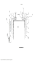
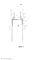
[0013] As Figuras 1 a 13 são vistas em corte horizontais similares através de um corrugador pulsante que mostram uma sequência de etapas usadas na fabricação do cano de parede dupla corrugado em que tanto o corrugador quanto o método de fabricação permitem a formação de uma conexão macho integral de cavilha como parte do cano de parede dupla corrugado moldado.[0013] Figures 1 to 13 are similar horizontal sectional views through a pulsating corrugator that show a sequence of steps used in the manufacture of the corrugated double-wall pipe in which both the corrugator and the manufacturing method allow the formation of a connection integral dowel core as part of molded corrugated double wall pipe.
[0014] A Figura 1, nos desenhos, é uma vista transversal horizontal através do túnel de molde em movimento 2 que mostra adicionalmente uma porção da cabeça de molde 1 para extrudar o filme plástico 17 para formação da parede corrugada externa e extrudar o filme plástico 15 para formação da parede lisa interna do cano de parede dupla corrugado. Os filmes plásticos extrudados, em combinação com os blocos de molde em movimento e o plugue de resfriamento 22, cooperam para formar o cano de parede dupla corrugado 200.[0014] Figure 1 in the drawings is a horizontal cross-sectional view through the moving
[0015] Na Figura 1, o túnel de molde 2 compreende blocos de molde primários e pelo menos um bloco de molde secundário. Os blocos de molde primários incluem o bloco de molde a montante 3, o bloco de molde intermediário 5 e o bloco de molde a jusante 7. Um bloco de molde secundário 11 é mostrado para formar seletivamente uma conexão de cavilha. Embora blocos de molde secundários adicionais possam cooperar, apenas um bloco de molde secundário que forma a conexão de cavilha em linha é mostrado.[0015] In Figure 1, the
[0016] A Figura 1 também mostra a formação parcial da corrugação 21 que está imediatamente a montante do plugue de resfriamento 22.[0016] Figure 1 also shows the partial formation of the
[0017] O ar de suporte 20 é fornecido no vão entre os dois filmes plásticos 15 e 17 para auxiliar na sustentação do filme plástico 17 e a deformação para fora do mesmo para trazê-lo em contato com a cavidade de corrugação do bloco de molde a montante 3. Uma vez que o filme 17 se aproxima da parede externa de bloco de molde 3, o vácuo variável segmentado 300 fornece uma assistência de vácuo variável para puxar o filme plástico 17 contra o formato externo do bloco de molde e, em particular, contra as cavidades que formam as corrugações. Um equilíbrio da pressão de ar 20 é exigido para incentivar de modo eficaz o filme a se mover para fora na corrugação 21, mas não tão grande a ponto de soprar o filme ou distorcer o filme 17 a montante da corrugação 25. Na Figura 1, pode-se ver que a superfície de projeção 25 está em proximidade da saída de extrusão para o filme plástico 17. Com este arranjo, há menos tendência de que o filme 17 seja distorcido ou soprado a montante, mas a pressão de ar 20 não pode ser muito grande.[0017]
[0018] Há arranjos diferentes para essencialmente controlar a força de vácuo exercida através de cada cavidade de corrugação de quaisquer dos blocos de mole. A função LIGA/DESLIGA e/ou capacidade de ajuste é definida pelo controlador 350 que também controla a sequência do bloco de molde.[0018] There are different arrangements for essentially controlling the vacuum force exerted through each corrugation cavity of any of the mole blocks. The ON/OFF function and/or adjustability is defined by the
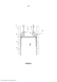
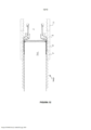
[0019] Como pode-se verificar, o vácuo associado à corrugação 21 (aplicado através do bloco de molde) apenas terá eficácia à medida que o vão entre o filme 17 e a parede externa da corrugação se estreita. Se o vão for muito grande, então a pressão de ar pode vazar facilmente no filme 17 e efetivamente destruir a força de vácuo no mesmo, particularmente quando os blocos de molde são liberados, conforme mostrado na Figura 2. Para compensar isso, a pressão de ar 20 incentiva o filme a se mover para fora e pelo menos sustentar a corrugação.[0019] As can be seen, the vacuum associated with the corrugation 21 (applied through the mold block) will only be effective as the gap between the
[0020] Quando os blocos de molde principais 3, 5 e 7 formarem o cano corrugado, a pressão de ar 20 é ajustada para um nível menor quando o bloco de molde a montante 3 se separar para fora, conforme mostrado na Figura 2. Nessa posição, a corrugação 21 acabou de ser formada e o filme plástico 17 permanece um tanto quanto macio e deformável. Ademais, a pressão de ar 20 atua agora sobre toda a corrugação 21 que não é sustentada, bem como a porção do filme que leva à corrugação 21.[0020] When the main mold blocks 3, 5 and 7 form the corrugated pipe, the
[0021] Na posição mostrada na Figura 2, a pressão de ar é preferivelmente diminuída a um nível para continuar a sustentar a corrugação 21, mas não tão grande a ponto de causar a deformação a montante do filme 17 ou de causar a deformação para fora da corrugação 21. Alguma deformação marginal da corrugação 21 será corrigida quando o bloco de molde 3 reengatar essa corrugação, conforme mostrado na Figura 3. A fonte de vácuo associada ao bloco de molde 3 é interrompida temporariamente.[0021] In the position shown in Figure 2, the air pressure is preferably decreased to a level to continue to support the
[0022] A Figura 2 mostra o bloco de molde a montante 3 parcialmente deslocado a montante, enquanto a Figura 3 mostra o bloco de molde a montante 3 em uma posição reengatando a corrugação 21 com a célula de corrugação última ou mais a jusante do bloco de molde. A cavilha secundária que forma o bloco de molde 11 se moveu com o bloco de molde a montante 3. Na Figura 3, a pressão de ar 20 é mantida no nível de sustentação e a força de vácuo é reaplicada para auxiliar o movimento do filme plástico para formar a corrugação. Nessa posição, a pressão de ar é definida para incentivar filmes de plástico para engatar os blocos de molde na maneira mostrada e para evitar incrustação a montante do filme plástico 17.[0022] Figure 2 shows the
[0023] Quando uma borda de arrasto de uma projeção para dentro de um bloco de molde, tal como a borda 29 na Figura 1, coopera com a cabeça de molde para formar uma vedação a montante, a pressão de ar pode ser aumentada temporariamente ou pulsada para auxiliar o movimento para fora do filme. Cada cavidade de corrugação dos blocos de molde tem tal borda de arrasto que coopera com a cabeça de molde.[0023] When a trailing edge of a projection into a mold block, such as
[0024] Na Figura 3, o bloco de molde intermediário 5 agora se separou do cano corrugado 200 e se moveu parcialmente a montante. O bloco de molde de força de vácuo 5 é desligado. A força de vácuo é aplicada à corrugação única 21 através da cavidade de corrugação 27.[0024] In Figure 3, the
[0025] Na Figura 4, tanto o bloco de molde intermediário 5 quanto o bloco de molde a jusante 7, liberaram e se moveram a montante cada um para reengatar o cano corrugado.[0025] In Figure 4, both the
[0026] Na Figura 4, o vácuo associado a cada cavidade de corrugação dos blocos de molde 5 e 7 é totalmente LIGADO para auxiliar no resfriamento adicional das corrugações formadas. À medida que as corrugações são resfriadas, o "encolhimento" ocorre e o ar pode vazar nos vãos entre o cano formado e os blocos de molde. Esse ar vazado fornece resfriamento adicional. No bloco de molde 3, as três corrugações totalmente formadas têm o vácuo LIGADO. A corrugação mais a montante tem o vácuo DESLIGADO até que a borda de arrasto 29 está essencialmente oposta à saída de cabeça de molde associada ao filme 17, sendo que em tal momento o vácuo é LIGADO.[0026] In Figure 4, the vacuum associated with each corrugation cavity of the
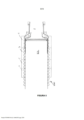
[0027] Na Figura 5, o bloco de molde secundário 11, foi ativada pelo controlador 300 e se moveu ao longo do plugue de resfriamento 22 e segue o bloco de molde a montante 3. Os blocos de molde intermediários e a jusante também se moverá mais a jusante antes de desengatar o cano corrugado ou começar seu movimento a montante de retorno. Os blocos de molde primários 3, 5 e 7 podem ter o vácuo LIGADO.[0027] In Figure 5, the secondary mold block 11 has been activated by the
[0028] O bloco de molde secundário 11 forma corrugações de diâmetro reduzido e, nessa modalidade preferida, todas essas corrugações foram fornecidas com um recesso central que recebe um anel “0”. A primeira corrugação de cavilha totalmente formada 3 na Figura 5 tem o vácuo LIGADO com a pressão de ar superior até que o bloco de molde seja liberado.[0028] The secondary mold block 11 forms corrugations of reduced diameter and, in this preferred embodiment, all these corrugations were provided with a central recess that receives a “0” ring. The first fully formed
[0029] Na Figura 5, os filmes plásticos 15 e 17 estão em engate com o bloco de molde secundário 11 e o bloco de molde secundário está a ponto de se separar da cavilha formada e se mover para fora em relação ao plugue de resfriamento 22. Esse aspecto é mostrado na Figura 6 em que tanto o bloco de molde secundário 11 quanto o bloco de molde a montante 3 liberaram o cano corrugado 100 e se movem a montante. Com esses blocos de molde separados do cano corrugado e cavilha, a pressão de ar 20 é reduzida para evitar a deformação da corrugação de cavilha mais a montante 31 que é majoritariamente autossustentada. A pressão de ar 20 é suficiente para auxiliar na manutenção da corrugação 31, até o momento em que o bloco de molde a montante 3 possa reengatar e sustentar as porções de corrugação da cavilha.[0029] In Figure 5, the
[0030] A Figura 7 mostra movimento adicional tanto do bloco de molde a montante 3 quanto do bloco de molde secundário 11.[0030] Figure 7 shows additional movement of both the
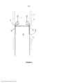
[0031] A Figura 8 mostra que o bloco de molde a montante 3 agora se moveu para dentro e reengata e sustenta a corrugação a montante 31 da porção de cavilha 33. As cavidades de corrugação do bloco de molde a montante 3 são de diâmetro maior que o diâmetro das corrugações de cavilha. Contudo, essas cavidades são suficientes para sustentar e resfriar as corrugações de cavilha. Dessa forma, o bloco de molde a montante 3 e as cavidades de corrugação do mesmo são projetados para sustentar a última corrugação de cavilha formada 31 e o bloco de molde intermediário 5 sustentará as demais corrugações formadas da cavilha. A pressão de ar 20 na Figura 8 está no nível de sustentação reduzido para evitar a deformação a montante sobre a cabeça de molde.[0031] Figure 8 shows that the
[0032] A força de vácuo pode ser reduzida quando quaisquer dos blocos de molde primários 3, 5 e 7 sustentam corrugações de cavilha.[0032] The vacuum force can be reduced when any of the primary mold blocks 3, 5 and 7 support dowel corrugations.
[0033] Conforme mostrado na Figura 9, o bloco de molde intermediário 5 liberou o cano corrugado 200 e se move para frente para cooperar com o bloco de molde a montante 3 para sustentar uma porção a jusante da cavilha formada.[0033] As shown in Figure 9, the
[0034] Na Figura 10, o bloco de molde intermediário 5 sustenta agora as corrugações adicionais da cavilha. Novamente, o tamanho de célula real das cavidades de corrugação do bloco de molde intermediário 5 são superdimensionados em relação às corrugações de cavilha formadas, mas essas cavidades fornecem sustentação e resfriamento adicional da corrugação de cavilha. O vácuo aplicado às células de corrugação individuais do bloco de molde intermediário 5, bem como pelo menos a última cavidade de corrugação do bloco de molde a montante 3, podem ser reduzidos ou podem ser menos eficazes (devido ao vazamento de ar) quando as corrugações de cavilha estão presentes. A força de vácuo é suficiente para manter o formato externo, mas não para puxar a face externa da corrugação de cavilha formada em engate pleno com as cavidades de corrugação. As corrugações da porção de cavilha são de diâmetro reduzido necessário para formar uma conexão apropriada com um conector fêmea que possa estar no mesmo diâmetro que o cano formado, se cada cano tiver uma cavilha respectiva. Alternativamente, o conector fêmea tem duas cavidades com uma dimensionada para vedar com o cano corrugado de tamanho completo e uma segunda cavidade para engatar uma cavilha. Portanto, o vácuo aplicado durante esse tempo de processo é reduzido.[0034] In Figure 10, the
[0035] Na Figura 11, o bloco de molde a jusante 7 agora se separou do cano de corrugação e se move em uma direção a montante.[0035] In Figure 11, the downstream mold block 7 has now separated from the corrugation pipe and moves in an upstream direction.
[0036] Na Figura 12, o bloco de molde a jusante 7 se reengatou com as corrugações do cano.[0036] In Figure 12, the downstream mold block 7 reengaged with the corrugations of the pipe.
[0037] A Figura 13 mostra uma posição adicional do cano corrugado em que a pulsação dos blocos de molde ocorreu e o bloco de molde a jusante 7 engata algumas corrugações da cavilha. Com o bloco de molde nessa posição, a força de vácuo é majoritariamente usada para criar um fluxo de ar para resfriamento adicional e o formato externo das corrugações de cavilha é definido. Pode-se ver na Figura 13 que o bloco de molde a montante 3 está a ponto de desengatar o cano corrugado e o bloco de molde 3 será pulsado a montante para formar corrugações adicionais. O bloco de molde secundário 11 não engatará o filme plástico 17 e pode ser denominado como em uma posição estacionária ou estacionária em movimento.[0037] Figure 13 shows an additional position of the corrugated pipe in which pulsation of the mold blocks has occurred and the downstream mold block 7 engages some corrugations of the dowel. With the mold block in this position, the vacuum force is mostly used to create an air flow for additional cooling and the external shape of the dowel corrugations is defined. It can be seen from Figure 13 that the
[0038] Um controlador é usado para determinar quando o bloco de molde secundário 11 será usado para formar uma conexão de cavilha.[0038] A controller is used to determine when the secondary mold block 11 will be used to form a dowel connection.
[0039] Isso pode ser definido de acordo com um comprimento de cano programado, tal como uma cavilha é formada em pontos pré-determinados ou o controlador pode ser definido para formar uma cavilha em posições diferentes.[0039] This can be set according to a programmed barrel length, such as a dowel is formed at predetermined points or the controller can be set to form a dowel at different positions.
[0040] As Figuras e a descrição acima baseiam-se no bloco de molde secundário 11 e são usadas apenas uma vez para formação da conexão de cavilha. Contudo, pode-se verificar que o bloco de molde poderia ser separado do cano e trazido de volta em contato com o cano para formar uma cavilha mais longa, caso desejado. Blocos de molde secundários múltiplos adicionais podem ser usados.[0040] The above Figures and description are based on the secondary mold block 11 and are used only once for forming the dowel connection. However, it will be appreciated that the mold block could be detached from the barrel and brought back into contact with the barrel to form a longer dowel, if desired. Additional multiple secondary mold blocks can be used.
[0041] Os três blocos de molde principais 3, 5 e 7 são uma modalidade preferencial; contudo, o sistema pode operar de modo satisfatório com apenas dois blocos de molde principais ou um número maior de blocos de molde. Também pode- se verificar que o bloco de molde secundário 11 não precisa ser um bloco de molde único, mas pode ser uma pluralidade de blocos de molde. Adicionar blocos de molde adicionais pode ser útil no deslocamento dos blocos de molde de volta para as posições a montante. Os blocos de molde primários foram descritos como separados do bloco de molde secundário, mas o bloco de molde secundário poderia incluir várias corrugações de tamanho completo. O presente arranjo permite que blocos de molde tanto primários quanto secundários sejam sustentados e se movam de forma comum.[0041] The three main mold blocks 3, 5 and 7 are a preferred embodiment; however, the system can operate satisfactorily with only two main mold blocks or a larger number of mold blocks. It can also be seen that the secondary mold block 11 need not be a single mold block, but can be a plurality of mold blocks. Adding additional mold blocks can be helpful in moving the mold blocks back to their upstream positions. The primary mold blocks were described as separate from the secondary mold block, but the secondary mold block could include multiple full size corrugations. The present arrangement allows both primary and secondary mold blocks to be supported and moved in a common manner.
[0042] Com o arranjo acima, é possível formar conexões de cavilha em linha como parte integral do cano corrugado através do uso do corrugador pulsante e do método descrito neste documento.[0042] With the above arrangement, it is possible to form in-line dowel connections as an integral part of the corrugated pipe through the use of the pulsating corrugator and the method described in this document.
[0043] Embora várias modalidades preferenciais da presente invenção tenham sido descritas no presente documento em detalhes, será observado por aqueles versados na técnica que variações podem ser feitas às mesmas sem se afastar das reivindicações anexas.[0043] While several preferred embodiments of the present invention have been described herein in detail, it will be appreciated by those skilled in the art that variations can be made thereto without departing from the appended claims.
Claims (5)
Applications Claiming Priority (3)
| Application Number | Priority Date | Filing Date | Title |
|---|---|---|---|
| CA2,946,104 | 2016-10-21 | ||
| CA2946104A CA2946104C (en) | 2016-10-21 | 2016-10-21 | Pulsating pipe mold with spigot connector |
| PCT/CA2017/051254 WO2018072032A1 (en) | 2016-10-21 | 2017-10-20 | Pulsating pipe mold with spigot connector |
Publications (2)
| Publication Number | Publication Date |
|---|---|
| BR112019008087A2 BR112019008087A2 (en) | 2019-07-23 |
| BR112019008087B1 true BR112019008087B1 (en) | 2023-02-07 |
Family
ID=61968928
Family Applications (1)
| Application Number | Title | Priority Date | Filing Date |
|---|---|---|---|
| BR112019008087-2A BR112019008087B1 (en) | 2016-10-21 | 2017-10-20 | PULSE CORRUGATOR WITH DOWN CONNECTION |
Country Status (9)
| Country | Link |
|---|---|
| US (1) | US10759108B2 (en) |
| EP (1) | EP3529043B1 (en) |
| CN (1) | CN110062689B (en) |
| AU (1) | AU2017347020B2 (en) |
| BR (1) | BR112019008087B1 (en) |
| CA (1) | CA2946104C (en) |
| MX (1) | MX2019004548A (en) |
| RU (1) | RU2753186C2 (en) |
| WO (1) | WO2018072032A1 (en) |
Families Citing this family (1)
| Publication number | Priority date | Publication date | Assignee | Title |
|---|---|---|---|---|
| CN108859054B (en) * | 2018-08-07 | 2023-12-05 | 江苏烨欣塑业有限公司 | HDPE farmland irrigation pipe preparation method, HDPE farmland irrigation pipe and manufacturing device |
Family Cites Families (13)
| Publication number | Priority date | Publication date | Assignee | Title |
|---|---|---|---|---|
| US3981663A (en) * | 1973-09-10 | 1976-09-21 | Lupke Gerd Paul Heinrich | Apparatus for making high speed corrugated plastic tubing |
| CA1083765A (en) * | 1976-12-01 | 1980-08-19 | Gerd P. H. Lupke | Apparatus for producing thermoplastic tubing |
| SU1238826A1 (en) * | 1984-12-25 | 1986-06-23 | Предприятие П/Я Р-6378 | Arrangement for producing corrugated tubes from billets-tubes |
| US4789322A (en) * | 1987-11-23 | 1988-12-06 | Harry Chan | Corrugator with intermeshing overlapping moldblock halves |
| CA2072663C (en) * | 1992-06-29 | 1999-11-16 | Manfred A. A. Lupke | Method and apparatus for forming a double walled thermoplastic tube with integral bells |
| CA2231624C (en) * | 1998-03-09 | 2001-02-06 | Manfred A. A. Lupke | Pipe molding apparatus with air float of plastic onto tapered cooling plug |
| CA2307798C (en) | 2000-05-08 | 2005-12-06 | Manfred A. A. Lupke | Pipe mold with compensation for pipe shrinkage |
| DE60143992D1 (en) * | 2000-09-11 | 2011-03-17 | Manfred Arno Alfred Lupke | CASTING MACHINE WITH A FLOATING FORM TUNNEL WITH THE ABILITY TO MAKE VARIOUS PRODUCT FORMS |
| WO2002070238A1 (en) * | 2001-03-02 | 2002-09-12 | Lupke Manfred Arno Alfred | Method and device for producing a double-walled thermoplastic pipe with integral pipe bell |
| CN1234521C (en) * | 2003-08-26 | 2006-01-04 | 甘国工 | Method for forming integrated double-wall bell socket of plastic corrugated pipe forming machine and its equipment |
| US8579624B2 (en) * | 2008-02-11 | 2013-11-12 | Advanced Drainage Systems, Inc. | Systems and methods for making multi-wall corrugated pipe |
| CA2872849A1 (en) * | 2014-11-28 | 2016-05-28 | Manfred A. A. Lupke | Method for forming inline triple wall coupling connector |
| JP6493242B2 (en) * | 2016-02-15 | 2019-04-03 | オムロン株式会社 | Molding machine, control device, and molding device |
-
2016
- 2016-10-21 CA CA2946104A patent/CA2946104C/en active Active
-
2017
- 2017-10-20 WO PCT/CA2017/051254 patent/WO2018072032A1/en unknown
- 2017-10-20 RU RU2019114412A patent/RU2753186C2/en active
- 2017-10-20 CN CN201780076708.7A patent/CN110062689B/en active Active
- 2017-10-20 US US16/388,111 patent/US10759108B2/en active Active
- 2017-10-20 BR BR112019008087-2A patent/BR112019008087B1/en active IP Right Grant
- 2017-10-20 MX MX2019004548A patent/MX2019004548A/en unknown
- 2017-10-20 AU AU2017347020A patent/AU2017347020B2/en active Active
- 2017-10-20 EP EP17862958.0A patent/EP3529043B1/en active Active
Also Published As
| Publication number | Publication date |
|---|---|
| CN110062689A (en) | 2019-07-26 |
| AU2017347020B2 (en) | 2021-10-21 |
| RU2019114412A (en) | 2020-11-23 |
| US20190299516A1 (en) | 2019-10-03 |
| CA2946104A1 (en) | 2018-04-21 |
| RU2753186C2 (en) | 2021-08-12 |
| AU2017347020A1 (en) | 2019-05-30 |
| CA2946104C (en) | 2021-10-26 |
| CN110062689B (en) | 2021-07-23 |
| EP3529043A4 (en) | 2020-06-10 |
| RU2019114412A3 (en) | 2021-02-25 |
| WO2018072032A1 (en) | 2018-04-26 |
| BR112019008087A2 (en) | 2019-07-23 |
| MX2019004548A (en) | 2019-09-26 |
| US10759108B2 (en) | 2020-09-01 |
| EP3529043B1 (en) | 2021-09-29 |
| EP3529043A1 (en) | 2019-08-28 |
Similar Documents
| Publication | Publication Date | Title |
|---|---|---|
| US3751541A (en) | Process of forming plastic tubing which is partially corrugated | |
| EP1874523B1 (en) | Method and apparatus for film extrusion | |
| BR112019008087B1 (en) | PULSE CORRUGATOR WITH DOWN CONNECTION | |
| BRPI0514508B1 (en) | film die head for blown tubular film production | |
| WO2012032195A2 (en) | Device and method for producing the mouths of biaxially oriented plastic tubes with integrated sealing gaskets | |
| BR112017003300B1 (en) | PIPE CORRUGATOR WITH DISENGAGEMENT MOLD BLOCKS AND DISCONNECTING METHOD | |
| CN103656825A (en) | Multiple lumen hose | |
| ES2548443T3 (en) | Aligning cooling plug for extruder | |
| WO2008087235A1 (en) | System for producing integral openings for biaxially oriented plastic pipes | |
| JP2009029104A (en) | Feed block, molding device for stacked resin film or sheet, and method for producing the same | |
| CN107511983A (en) | A kind of forming extrusion of plastic pipe mould | |
| CN206749013U (en) | Blow moulding machine multilayer extrusion folding mould device | |
| PT100002B (en) | Profile of thermoplastic resin alveolar structure Profile of extrusion for the capture of the profile and its process of manufacture | |
| JP6415177B2 (en) | Method for producing synthetic resin molding | |
| CN1221375C (en) | Pipe mold with compensation for pipe shrinkage | |
| JP2016527113A (en) | Method for manufacturing bags by inflation film extrusion | |
| JP2001201160A (en) | Duct having ribs and method for manufacturing the same | |
| CN220661675U (en) | Core assembly capable of being adjusted rapidly | |
| JP7349061B2 (en) | Molding method | |
| JP2008272989A (en) | Feed block, apparatus for molding laminated resin film or sheet, and method for producing laminated resin film or sheet | |
| JPH0420594Y2 (en) | ||
| JP2023005405A (en) | Sheet molded mouthpiece | |
| JPH0545914Y2 (en) | ||
| PT2008139004W (en) | Method for manufacturing a three-layer corrugated pipe, head therefor and the resulting pipe | |
| BR102017024816A2 (en) | FLEXIBLE DUTY FOR AIR CONDITIONING AND RESPECTIVE MANUFACTURING PROCESS |
Legal Events
| Date | Code | Title | Description |
|---|---|---|---|
| B06W | Patent application suspended after preliminary examination (for patents with searches from other patent authorities) chapter 6.23 patent gazette] | ||
| B350 | Update of information on the portal [chapter 15.35 patent gazette] | ||
| B06A | Patent application procedure suspended [chapter 6.1 patent gazette] | ||
| B09A | Decision: intention to grant [chapter 9.1 patent gazette] | ||
| B16A | Patent or certificate of addition of invention granted [chapter 16.1 patent gazette] |
Free format text: PRAZO DE VALIDADE: 20 (VINTE) ANOS CONTADOS A PARTIR DE 20/10/2017, OBSERVADAS AS CONDICOES LEGAIS |