BR112018002719B1 - THERMODYNAMIC ENGINE - Google Patents
THERMODYNAMIC ENGINE Download PDFInfo
- Publication number
- BR112018002719B1 BR112018002719B1 BR112018002719-7A BR112018002719A BR112018002719B1 BR 112018002719 B1 BR112018002719 B1 BR 112018002719B1 BR 112018002719 A BR112018002719 A BR 112018002719A BR 112018002719 B1 BR112018002719 B1 BR 112018002719B1
- Authority
- BR
- Brazil
- Prior art keywords
- expander
- fluid
- thermodynamic engine
- engine
- separator
- Prior art date
Links
Images

Classifications
-
- F—MECHANICAL ENGINEERING; LIGHTING; HEATING; WEAPONS; BLASTING
- F01—MACHINES OR ENGINES IN GENERAL; ENGINE PLANTS IN GENERAL; STEAM ENGINES
- F01K—STEAM ENGINE PLANTS; STEAM ACCUMULATORS; ENGINE PLANTS NOT OTHERWISE PROVIDED FOR; ENGINES USING SPECIAL WORKING FLUIDS OR CYCLES
- F01K25/00—Plants or engines characterised by use of special working fluids, not otherwise provided for; Plants operating in closed cycles and not otherwise provided for
- F01K25/06—Plants or engines characterised by use of special working fluids, not otherwise provided for; Plants operating in closed cycles and not otherwise provided for using mixtures of different fluids
-
- F—MECHANICAL ENGINEERING; LIGHTING; HEATING; WEAPONS; BLASTING
- F01—MACHINES OR ENGINES IN GENERAL; ENGINE PLANTS IN GENERAL; STEAM ENGINES
- F01B—MACHINES OR ENGINES, IN GENERAL OR OF POSITIVE-DISPLACEMENT TYPE, e.g. STEAM ENGINES
- F01B29/00—Machines or engines with pertinent characteristics other than those provided for in preceding main groups
- F01B29/08—Reciprocating-piston machines or engines not otherwise provided for
- F01B29/10—Engines
-
- F—MECHANICAL ENGINEERING; LIGHTING; HEATING; WEAPONS; BLASTING
- F01—MACHINES OR ENGINES IN GENERAL; ENGINE PLANTS IN GENERAL; STEAM ENGINES
- F01K—STEAM ENGINE PLANTS; STEAM ACCUMULATORS; ENGINE PLANTS NOT OTHERWISE PROVIDED FOR; ENGINES USING SPECIAL WORKING FLUIDS OR CYCLES
- F01K21/00—Steam engine plants not otherwise provided for
- F01K21/04—Steam engine plants not otherwise provided for using mixtures of steam and gas; Plants generating or heating steam by bringing water or steam into direct contact with hot gas
-
- F—MECHANICAL ENGINEERING; LIGHTING; HEATING; WEAPONS; BLASTING
- F01—MACHINES OR ENGINES IN GENERAL; ENGINE PLANTS IN GENERAL; STEAM ENGINES
- F01K—STEAM ENGINE PLANTS; STEAM ACCUMULATORS; ENGINE PLANTS NOT OTHERWISE PROVIDED FOR; ENGINES USING SPECIAL WORKING FLUIDS OR CYCLES
- F01K7/00—Steam engine plants characterised by the use of specific types of engine; Plants or engines characterised by their use of special steam systems, cycles or processes; Control means specially adapted for such systems, cycles or processes; Use of withdrawn or exhaust steam for feed-water heating
- F01K7/16—Steam engine plants characterised by the use of specific types of engine; Plants or engines characterised by their use of special steam systems, cycles or processes; Control means specially adapted for such systems, cycles or processes; Use of withdrawn or exhaust steam for feed-water heating the engines being only of turbine type
-
- F—MECHANICAL ENGINEERING; LIGHTING; HEATING; WEAPONS; BLASTING
- F03—MACHINES OR ENGINES FOR LIQUIDS; WIND, SPRING, OR WEIGHT MOTORS; PRODUCING MECHANICAL POWER OR A REACTIVE PROPULSIVE THRUST, NOT OTHERWISE PROVIDED FOR
- F03G—SPRING, WEIGHT, INERTIA OR LIKE MOTORS; MECHANICAL-POWER PRODUCING DEVICES OR MECHANISMS, NOT OTHERWISE PROVIDED FOR OR USING ENERGY SOURCES NOT OTHERWISE PROVIDED FOR
- F03G6/00—Devices for producing mechanical power from solar energy
- F03G6/003—Devices for producing mechanical power from solar energy having a Rankine cycle
-
- F—MECHANICAL ENGINEERING; LIGHTING; HEATING; WEAPONS; BLASTING
- F22—STEAM GENERATION
- F22B—METHODS OF STEAM GENERATION; STEAM BOILERS
- F22B1/00—Methods of steam generation characterised by form of heating method
- F22B1/02—Methods of steam generation characterised by form of heating method by exploitation of the heat content of hot heat carriers
- F22B1/08—Methods of steam generation characterised by form of heating method by exploitation of the heat content of hot heat carriers the heat carrier being steam
- F22B1/14—Methods of steam generation characterised by form of heating method by exploitation of the heat content of hot heat carriers the heat carrier being steam coming in direct contact with water in bulk or in sprays
-
- F—MECHANICAL ENGINEERING; LIGHTING; HEATING; WEAPONS; BLASTING
- F22—STEAM GENERATION
- F22B—METHODS OF STEAM GENERATION; STEAM BOILERS
- F22B1/00—Methods of steam generation characterised by form of heating method
- F22B1/02—Methods of steam generation characterised by form of heating method by exploitation of the heat content of hot heat carriers
- F22B1/18—Methods of steam generation characterised by form of heating method by exploitation of the heat content of hot heat carriers the heat carrier being a hot gas, e.g. waste gas such as exhaust gas of internal-combustion engines
- F22B1/1853—Methods of steam generation characterised by form of heating method by exploitation of the heat content of hot heat carriers the heat carrier being a hot gas, e.g. waste gas such as exhaust gas of internal-combustion engines coming in direct contact with water in bulk or in sprays
-
- Y—GENERAL TAGGING OF NEW TECHNOLOGICAL DEVELOPMENTS; GENERAL TAGGING OF CROSS-SECTIONAL TECHNOLOGIES SPANNING OVER SEVERAL SECTIONS OF THE IPC; TECHNICAL SUBJECTS COVERED BY FORMER USPC CROSS-REFERENCE ART COLLECTIONS [XRACs] AND DIGESTS
- Y02—TECHNOLOGIES OR APPLICATIONS FOR MITIGATION OR ADAPTATION AGAINST CLIMATE CHANGE
- Y02E—REDUCTION OF GREENHOUSE GAS [GHG] EMISSIONS, RELATED TO ENERGY GENERATION, TRANSMISSION OR DISTRIBUTION
- Y02E10/00—Energy generation through renewable energy sources
- Y02E10/40—Solar thermal energy, e.g. solar towers
- Y02E10/46—Conversion of thermal power into mechanical power, e.g. Rankine, Stirling or solar thermal engines
Abstract
MOTOR TERMODINÂMICO. Um expansor do tipo de pistão (2) e cilindro (3) tem invertida a sua orientação normal, com o virabrequim (4) na posição mais alta e a cabeça do cilindro (5) na posição mais baixa. A cabeça de cilindro tem um par de injetores de líquido (6, 7) orientados para os líquidos respectivos pentano e glicerina a serem injetados em forma de neblina em contato entre si no fundo do cilindro. O pentano é vaporizado por transferência do calor latente para ele a partir da glicerina. São propostas válvulas injetoras respectivas (9, 10) provenientes de trilhos de alta pressão (11, 12) alimentadas por bombas (14, 15). Uma válvula de descarga 18 leva a um separador de ciclone (19) em que se faz a corrente de descarga rodopiar, resultando em névoa e gotículas de glicerina voando para fora para a parede (20) do separador e correndo para o seu fundo (21), de onde ele é drenado periodicamente sob o controle de uma válvula flutuante (22). O vapor de pentano é extraído do centro (23) do topo do separador. Deve ser observado que os trajetos de fluido do motor são fechados. Faz-se passar o vapor de pentano para um condensador (26). Do fundo deste, também por meio de uma válvula flutuante (27), é drenado o pentano líquido. Os líquidos respectivos (...).THERMODYNAMIC ENGINE. A piston (2) and cylinder (3) type expander has its normal orientation reversed, with the crankshaft (4) in the highest position and the cylinder head (5) in the lowest position. The cylinder head has a pair of liquid injectors (6, 7) oriented towards the respective liquids pentane and glycerin to be injected in the form of mist in contact with each other at the bottom of the cylinder. Pentane is vaporized by transferring latent heat to it from glycerin. Respective injection valves (9, 10) coming from high pressure rails (11, 12) fed by pumps (14, 15) are proposed. A discharge valve 18 leads to a cyclone separator (19) where the discharge stream is swirled, resulting in mist and glycerin droplets flying out onto the wall (20) of the separator and running down to its bottom (21). ), from which it is drained periodically under the control of a floating valve (22). The pentane vapor is drawn from the top center (23) of the separator. It should be noted that the engine fluid paths are closed. The pentane vapor is passed into a condenser (26). From the bottom of this, also by means of a floating valve (27), the liquid pentane is drained. The respective liquids (...).
Description
[001] A presente invenção se refere a um motor termodinâmico.[001] The present invention relates to a thermodynamic engine.
[002] Os motores termodinâmicos operam por expansão de um gás ou vapor, a que se refere abaixo como “fluido de trabalho”, a partir de uma pressão e temperatura elevadas para uma pressão e temperatura mais baixas, extraindo um trabalho útil no processo. Normalmente isto é efetuado em um motor de pistão e cilindro ou em uma turbina.[002] Thermodynamic engines operate by expanding a gas or steam, referred to below as the "working fluid", from a high pressure and temperature to a lower pressure and temperature, extracting useful work in the process. Usually this is done in a piston and cylinder engine or in a turbine.
[003] A elevação da pressão e da temperatura pode ser efetuada internamente como em um motor de combustão interna ou externamente como em uma turbina a vapor.[003] The pressure and temperature rise can be carried out internally as in an internal combustion engine or externally as in a steam turbine.
[004] Normalmente um único fluído de trabalho é usado, embora no caso de combustão interna, o fluido será provavelmente uma mistura de gases, especialmente nitrogênio do ar usado na combustão e nos produtos de combustão, especialmente dióxido de carbono e vapor de água.[004] Normally a single working fluid is used, although in the case of internal combustion, the fluid will likely be a mixture of gases, especially nitrogen from the air used in combustion, and the products of combustion, especially carbon dioxide and water vapour.
[005] É conhecida a prática de se fazer um líquido passar através de um motor, em forma de água, transformando-se em vapor úmido.[005] It is known the practice of making a liquid pass through an engine, in the form of water, transforming it into wet steam.
[006] A presente invenção se refere ao aquecimento do fluido de trabalho com um fluido diferente.[006] The present invention relates to heating the working fluid with a different fluid.
[007] O objetivo da presente invenção consiste em propor um motor termodinâmico melhorado.[007] The objective of the present invention is to propose an improved thermodynamic engine.
[008] De acordo com a invenção é proposto um motor termodinâmico que compreende: • um expansor termodinâmico para expandir o fluido de trabalho combinado com um segundo fluido; • um separador conectado a uma descarga do expansor para separar o segundo fluido do fluido de trabalho; • meios para fazer passar o segundo fluido para • um aquecedor para tal fim e, portanto, para • uma região de vaporização; • um condensador para condensar o fluido de trabalho da forma gasosa para uma forma de líquido volátil; e • meios para fazer o fluido de trabalho condensado na forma líquida passar para a região de vaporização para entrar em contato com o segundo fluido reaquecido para fazer o fluido de trabalho se volatilizar para a sua expansão produtora de trabalho no expansor.[008] According to the invention, a thermodynamic engine is proposed, comprising: • a thermodynamic expander for expanding the working fluid combined with a second fluid; • a separator connected to an expander discharge to separate the second fluid from the working fluid; • means for passing the second fluid to • a heater for this purpose and therefore to • a vaporization region; • a condenser to condense the working fluid from a gaseous form to a volatile liquid form; and • means for causing the condensed working fluid in liquid form to pass into the vaporization region to contact the reheated second fluid to cause the working fluid to volatilize for its work-producing expansion in the expander.
[009] O expansor pode ser tanto um dispositivo de deslocamento positivo tal como um expansor reciprocante, ou um dispositivo de deslocamento variável tal como uma turbina.[009] The expander can be either a positive displacement device such as a reciprocating expander, or a variable displacement device such as a turbine.
[0010] A região de vaporização pode se encontrar no interior do expansor, tal como o volume de ponto morto superior de um dispositivo reciprocante de pistão e cilindro, análogo à câmara de combustão de um motor de combustão interna, ou a uma região de entrada de uma turbina.[0010] The vaporization region can be found inside the expander, such as the top dead center volume of a piston and cylinder reciprocating device, analogous to the combustion chamber of an internal combustion engine, or an inlet region of a turbine.
[0011] Alternativamente, a região de vaporização pode se encontrar no exterior do expansor, de um modo análogo ao de uma caldeira de um motor/turbina a vapor, com a distinção de que se faz o segundo fluido reaquecido passar para dentro da caldeira juntamente com o fluido de trabalho condensado para entrar em contato íntimo para uma transferência de calor e uma vaporização do fluido de trabalho.[0011] Alternatively, the vaporization region can be found outside the expander, in a similar way to a boiler of a steam engine/turbine, with the distinction that the second reheated fluid is passed into the boiler together with the condensed working fluid to come into intimate contact for heat transfer and vaporization of the working fluid.
[0012] Normalmente, o segundo fluido será um líquido. O separador pode se encontrar ou do lado do expansor do condensador, quando então ele será um separador de líquido/vapor, ou do outro lado do condensador, sendo então um separador de líquido/líquido.[0012] Normally, the second fluid will be a liquid. The separator can be located either on the expander side of the condenser, in which case it will be a liquid/vapour separator, or on the other side of the condenser, in which case it will be a liquid/liquid separator.
[0013] Nas modalidades preferidas, o pentano é usado como o meio de alteração de fase e o glicerol (propano-1,2,3-triol) com uma adição opcional de propano- 1,2-diol é usado como um fluido transportador de calor.[0013] In preferred embodiments, pentane is used as the phase change medium and glycerol (propane-1,2,3-triol) with an optional addition of propane-1,2-diol is used as a carrier fluid of heat.
[0014] O segundo fluido pode ser aquecido de uma variedade de modos, tal como por calor residual e por energia solar.[0014] The second fluid can be heated in a variety of ways, such as by waste heat and by solar energy.
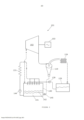
[0015] Para ajudar a compreender a invenção, duas modalidades específicas suas serão agora descritas a título de exemplo e fazendo referência aos desenhos apensos em que: a Figura 1 é um diagrama de blocos de um primeiro motor termodinâmico de acordo com a invenção, e a Figura 2 é um diagrama de blocos de um segundo motor termodinâmico de acordo com a presente invenção.[0015] To help understand the invention, two specific embodiments thereof will now be described by way of example and with reference to the accompanying drawings in which: Figure 1 is a block diagram of a first thermodynamic engine according to the invention, and Figure 2 is a block diagram of a second thermodynamic engine in accordance with the present invention.
[0016] Com referência à Figura 1, um motor termodinâmico 1 ali mostrado tem um expansor do tipo de pistão 2 e cilindro 3, tendo invertida a orientação normal do motor de combustão interna, com o virabrequim 4 na posição mais alta e a “cabeça” do cilindro 5 na posição mais baixa. A cabeça de cilindro tem um par de injetores de líquido 6, 7 orientados para que os seus respectivos líquidos pentano e glicerina sejam injetados em forma de névoa para entrarem em contato entre si no fundo do cilindro em uma região de vaporização 8 entre a posição do ponto morto “superior” do pistão e a cabeça de cilindro - sendo a posição de ponto morto “superior” a posição da aproximação máxima do pistão com a cabeça do cilindro e recebe a denominação de ponto morto “superior” por analogia com o termo em motores convenientemente orientados. O pentano é vaporizado para transferir o calor latente para ele da glicerina. São propostas válvulas injetores 9, 10 provenientes dos trilhos de alta pressão 11, 12 alimentados por bombas 14, 15.[0016] With reference to Figure 1, a thermodynamic engine 1 shown there has an expander of the type of
[0017] Também montado na cabeça do cilindro se encontra uma válvula de descarga 16 aberta por um excêntrico 17 acionado à velocidade do virabrequim por um acionamento por corrente - não mostrado deste modo. Uma tubulação de descarga 18 leva a um separador de ciclone 19. Neste, faz-se a corrente de descarga proveniente do motor rodopiar, fazendo-se com que a névoa e gotículas de glicerina voem da parede 20 do separador e corram para o seu fundo 21, de onde ela é drenada periodicamente sob o controle de uma válvula flutuante 22. O vapor de pentano é extraído do centro 23 do topo do separador. Deve ser observado que os trajetos de fluido do motor são fechados, ao contrário de serem abertos à atmosfera e o interior do separador é também fechado. Ele deve se encontrar a uma pressão e temperatura elevadas acima das condições ambientes.[0017] Also mounted on the cylinder head is a
[0018] Através da tubulação 25, o vapor de pentano passa para um condensador 26. Do fundo deste, também por meio de uma válvula flutuante 27 é drenado o pentano líquido. Os líquidos respectivos são canalizados para serem coletados em tanques 28, 29. Estes têm tampas vedadas. A tubulação para a glicerina é inclinada, de preferência, para baixo a partir do exaustor e na direção do separador, e em seguida para o tanque de glicerina para que a glicerina escorra por gravidade. Este é o motivo também para que o expansor seja disposto com a cabeça do cilindro voltada para baixo.[0018] Through
[0019] Do tanque de glicerina este líquido é bombeado por uma bomba de pressão baixa 30 para um aquecedor 31. Este pode ser de muitos tipos, tipicamente um trocador de calor a calor residual ou um coletor solar.[0019] From the glycerin tank this liquid is pumped by a
[0020] Em uso, o motor tem a probabilidade de acionar um gerador de eletricidade para gerar proporcionalmente ao calor disponível. Um sistema de controle 32 é previsto para regular o fluxo de glicerina de modo tal que ele sai do aquecedor a uma temperatura consideravelmente elevada, adequadamente 150°C. Os fluxos de glicerina quente provenientes do seu tanque e do pentano líquido do seu tanque são bombeados por bombas injetoras 14, 15, pressurizando os líquidos até pressões de trilhos de injetores.[0020] In use, the engine is likely to drive a generator to generate electricity in proportion to the available heat. A
[0021] O ciclo de operação para um cilindro prossegue do seguinte modo, iniciando com PMS: as quantidades dos dois meios determinados dinamicamente pelo sistema de controle são injetadas numa relação de tempo adequada de um para o outro e em relação à posição angular do motor. Quando tiver sido injetada uma quantidade suficiente dos dois meios (novamente calculada dinamicamente pelo sistema de controle), a injeção cessa. A partir deste ponto e até que o pistão atinja o fim do seu curso, o meio de troca de fase vaporizado se expande, acionando o pistão e fornecendo energia.[0021] The operating cycle for a cylinder proceeds as follows, starting with TDC: the quantities of the two media determined dynamically by the control system are injected in a suitable time relationship from one to the other and in relation to the angular position of the engine . When a sufficient amount of both media has been injected (again dynamically calculated by the control system), the injection ceases. From this point until the piston reaches the end of its stroke, the vaporized phase-change medium expands, driving the piston and providing energy.
[0022] No fim do curso, a válvula de descarga abre (e permanece aberta durante o curso de volta), descarregando os meios misturados na parte de recuperação de fluido do motor.[0022] At the end of the stroke, the discharge valve opens (and remains open during the return stroke), discharging the mixed media into the fluid recovery part of the engine.
[0023] Com referência agora à Figura 2, o motor termodinâmico 101 mostrado ali tem uma turbina 102 que aciona um gerador elétrico 103. A corrente de descarga da turbina passa para um separador 119 com o vapor de pentano passando para um condensador 124 e dali para um tanque de pentano líquido 129. Daqui ele é bombeado por uma bomba 139 contra a pressão elevada para uma caldeira 140.[0023] Referring now to Figure 2, the
[0024] A caldeira contém glicerina quente 141 com uma camada de topo 142 de pentano em ebulição. O pentano líquido é pulverizado sobre a superfície do pentano em ebulição e se vaporiza, transformando-se em vapor de pentano 143 na parte superior da caldeira. A glicerina é extraída do fundo do reservatório e é bombeada por uma bomba 144 para o aquecedor 131, de onde ela corre de volta ao reservatório e é pulverizada no vapor de pentano para maximizar a transferência de calor.[0024] The boiler contains
[0025] O vapor de pentano corre da caldeira a uma taxa controlada pela velocidade da turbina, ela mesma controlada pela carga do gerador. Este fluxo inclui névoa de glicerina. É esta glicerina que é separada pelo ciclone. A corrente de glicerina separada é devolvida à caldeira por uma outra bomba 145.[0025] The pentane steam flows from the boiler at a rate controlled by the turbine speed, itself controlled by the generator load. This flux includes glycerin mist. It is this glycerin that is separated by the cyclone. The separated glycerin stream is returned to the boiler by another
[0026] Deve ser observado que as modalidades descritas acima da invenção são variantes inéditas do Ciclo Orgânico de Rankine que torna desnecessária a exigência de qualquer trocador de calor do lado da entrada. Tal trocador de cal é substituído pela injeção direta da glicerina quente no pentano que efetua a alteração de fase do Ciclo Orgânico de Rankine.[0026] It should be noted that the above-described embodiments of the invention are unprecedented variants of the Organic Rankine Cycle which makes unnecessary the requirement of any heat exchanger on the inlet side. Such a lime exchanger is replaced by the direct injection of hot glycerin into the pentane which effects the phase change of the Organic Rankine Cycle.
[0027] A dispersão da glicerina transportadora de calor em gotículas extremamente pequenas em contato íntimo com o pentano de alteração de fase sobre uma área superficial maior do que poderia ser obtida com um trocador de calor convencional, funciona como um mecanismo eficiente e rápido de troca de calor. Isto evita a diferença de temperatura considerável e uma perda consequente de eficiência sofrida com um trocador de calor convencional.[0027] The dispersion of the heat-carrying glycerin in extremely small droplets in intimate contact with the phase-change pentane over a larger surface area than could be achieved with a conventional heat exchanger, serves as an efficient and rapid exchange mechanism of heat. This avoids the considerable temperature difference and a consequent loss in efficiency suffered with a conventional heat exchanger.
[0028] Como os ciclos do expansor são completamente fechados, não é produzida nenhuma corrente de descarga.[0028] As the expander cycles are completely closed, no discharge current is produced.
[0029] A presente invenção não se destina a ser restrita às modalidades descritas acima. O expansor reciprocante de pistão e cilindro, por exemplo, poderia consistir em um dispositivo de cilindros múltiplos.[0029] The present invention is not intended to be restricted to the embodiments described above. The reciprocating piston and cylinder expander, for example, could consist of a multiple cylinder device.
Claims (13)
Applications Claiming Priority (1)
| Application Number | Priority Date | Filing Date | Title |
|---|---|---|---|
| PCT/GB2015/052344 WO2017025700A1 (en) | 2015-08-13 | 2015-08-13 | Thermodynamic engine |
Publications (2)
| Publication Number | Publication Date |
|---|---|
| BR112018002719A2 BR112018002719A2 (en) | 2018-10-02 |
| BR112018002719B1 true BR112018002719B1 (en) | 2023-04-04 |
Family
ID=54186224
Family Applications (1)
| Application Number | Title | Priority Date | Filing Date |
|---|---|---|---|
| BR112018002719-7A BR112018002719B1 (en) | 2015-08-13 | 2015-08-13 | THERMODYNAMIC ENGINE |
Country Status (10)
| Country | Link |
|---|---|
| US (1) | US10787936B2 (en) |
| EP (1) | EP3334907B1 (en) |
| JP (1) | JP6690822B2 (en) |
| KR (1) | KR102353428B1 (en) |
| CN (1) | CN107923265B (en) |
| BR (1) | BR112018002719B1 (en) |
| CA (1) | CA2995424C (en) |
| MX (1) | MX2018001785A (en) |
| RU (1) | RU2711527C2 (en) |
| WO (1) | WO2017025700A1 (en) |
Families Citing this family (4)
| Publication number | Priority date | Publication date | Assignee | Title |
|---|---|---|---|---|
| JP6363313B1 (en) * | 2018-03-01 | 2018-07-25 | 隆逸 小林 | Working medium characteristic difference power generation system and working medium characteristic difference power generation method using the power generation system |
| GB2581770B (en) | 2019-01-14 | 2023-01-18 | Gas Expansion Motors Ltd | Engine |
| TR202016806A1 (en) * | 2020-10-21 | 2022-05-23 | Repg Enerji Sistemleri Sanayi Ve Ticaret Anonim Sirketi | a thermodynamic engine |
| TR202016802A2 (en) * | 2020-10-21 | 2022-05-23 | Repg Enerji Sistemleri Sanayi Ve Ticaret Anonim Sirketi | A MOTION PRODUCTION MECHANISM |
Family Cites Families (22)
| Publication number | Priority date | Publication date | Assignee | Title |
|---|---|---|---|---|
| JP3670319B2 (en) * | 1994-09-30 | 2005-07-13 | 株式会社日阪製作所 | Binary power generation system |
| JPH10274010A (en) * | 1997-03-31 | 1998-10-13 | Hisaka Works Ltd | Binary power generating system |
| RU2166103C2 (en) * | 1999-07-07 | 2001-04-27 | Романовский Владимир Федорович | Method and device for converting heat energy into mechanical work |
| UA64812C2 (en) * | 2001-03-12 | 2004-03-15 | Mykola Oleksandrovych Dykyi | Method for operation of steam-gas electric power plant on combined fuel (solid with gaseous or liquid) and steam-gas unit for its implementation |
| JP2002303105A (en) * | 2001-04-09 | 2002-10-18 | Mayekawa Mfg Co Ltd | Two-phase separation rankine cycle |
| BRPI0407136B1 (en) * | 2003-02-03 | 2014-04-01 | Kalex Inc | PROCESS TO IMPLEMENT A THERMODYNAMIC CYCLE |
| DE102004037417B3 (en) * | 2004-07-30 | 2006-01-19 | Siemens Ag | Method and device for transferring heat from a heat source to a thermodynamic cycle with a working medium comprising at least two substances with non-isothermal evaporation and condensation |
| EP1764487A1 (en) * | 2005-09-19 | 2007-03-21 | Solvay Fluor GmbH | Working fluid for a OCR-process |
| CN101454542A (en) * | 2006-04-04 | 2009-06-10 | 法国电力公司 | Piston steam engine having internal flash vapourisation of a working medium |
| EA014465B1 (en) * | 2006-08-25 | 2010-12-30 | Коммонвелт Сайентифик Энд Индастриал Рисерч Организейшн | A heat engine system |
| US9309785B2 (en) * | 2007-06-28 | 2016-04-12 | Averill Partners Llc | Air start steam engine |
| US7694514B2 (en) * | 2007-08-08 | 2010-04-13 | Cool Energy, Inc. | Direct contact thermal exchange heat engine or heat pump |
| EP2188500A2 (en) * | 2007-08-31 | 2010-05-26 | Siemens Aktiengesellschaft | Method and device for converting thermal energy into mechanical energy |
| GB2457266B (en) * | 2008-02-07 | 2012-12-26 | Univ City | Generating power from medium temperature heat sources |
| US20100034684A1 (en) * | 2008-08-07 | 2010-02-11 | General Electric Company | Method for lubricating screw expanders and system for controlling lubrication |
| DE102010022408B4 (en) * | 2010-06-01 | 2016-11-24 | Man Truck & Bus Ag | Method and apparatus for operating a steam cycle with lubricated expander |
| US8667797B2 (en) * | 2010-07-09 | 2014-03-11 | Purdue Research Foundation | Organic rankine cycle with flooded expansion and internal regeneration |
| CN201991580U (en) * | 2011-03-15 | 2011-09-28 | 中国电力工程顾问集团西南电力设计院 | Flue gas waste heat power generating system comprising ammonia steam turbine |
| JP2013083240A (en) * | 2011-09-26 | 2013-05-09 | Toyota Industries Corp | Waste heat recovery device |
| US20150000260A1 (en) * | 2013-06-26 | 2015-01-01 | Walter F. Burrows | Environmentally friendly power generation process |
| CN203655368U (en) * | 2013-11-19 | 2014-06-18 | 孟宁 | Cano-Rankine double-circulation hybrid efficient power generation equipment |
| US9957428B2 (en) * | 2013-12-20 | 2018-05-01 | 3M Innovative Properties Company | Fluorinated olefins as working fluids and methods of using same |
-
2015
- 2015-08-13 KR KR1020187007141A patent/KR102353428B1/en active IP Right Grant
- 2015-08-13 RU RU2018105270A patent/RU2711527C2/en active
- 2015-08-13 MX MX2018001785A patent/MX2018001785A/en unknown
- 2015-08-13 CN CN201580082486.0A patent/CN107923265B/en active Active
- 2015-08-13 JP JP2018507631A patent/JP6690822B2/en active Active
- 2015-08-13 BR BR112018002719-7A patent/BR112018002719B1/en active IP Right Grant
- 2015-08-13 US US15/752,398 patent/US10787936B2/en active Active
- 2015-08-13 WO PCT/GB2015/052344 patent/WO2017025700A1/en active Application Filing
- 2015-08-13 CA CA2995424A patent/CA2995424C/en active Active
- 2015-08-13 EP EP15767569.5A patent/EP3334907B1/en active Active
Also Published As
| Publication number | Publication date |
|---|---|
| JP2018527506A (en) | 2018-09-20 |
| MX2018001785A (en) | 2018-09-06 |
| CN107923265B (en) | 2021-01-15 |
| WO2017025700A1 (en) | 2017-02-16 |
| RU2018105270A3 (en) | 2019-08-14 |
| KR20180033300A (en) | 2018-04-02 |
| EP3334907B1 (en) | 2024-04-10 |
| CN107923265A (en) | 2018-04-17 |
| RU2018105270A (en) | 2019-08-14 |
| US20190003345A1 (en) | 2019-01-03 |
| WO2017025700A8 (en) | 2018-02-22 |
| CA2995424C (en) | 2022-10-18 |
| CA2995424A1 (en) | 2017-02-16 |
| US10787936B2 (en) | 2020-09-29 |
| EP3334907A1 (en) | 2018-06-20 |
| JP6690822B2 (en) | 2020-04-28 |
| RU2711527C2 (en) | 2020-01-17 |
| BR112018002719A2 (en) | 2018-10-02 |
| KR102353428B1 (en) | 2022-01-21 |
Similar Documents
| Publication | Publication Date | Title |
|---|---|---|
| KR101417143B1 (en) | Piston steam engine having internal flash vapourisation of a working medium | |
| US4747271A (en) | Hydraulic external heat source engine | |
| BR112018002719B1 (en) | THERMODYNAMIC ENGINE | |
| NO810419L (en) | ROTARY HEAT POWER MACHINERY. | |
| JP2015503048A (en) | Thermal energy storage system | |
| BRPI1003490B1 (en) | rankine cycle system and method | |
| CN104445481B (en) | A kind of waste heat electricity-water cogeneration system | |
| CN103925024B (en) | A kind of water-electricity cogeneration system and working procedure reclaiming desalination of sea water concentrated seawater waste heat | |
| BR112015022225B1 (en) | CLOSED-CYCLE PLANT, IN PARTICULAR FOR A RANKINE CYCLE, FOR CONVERTING THERMAL ENERGY INTO ELECTRICAL ENERGY, AND PROCESS FOR CONVERTING THERMAL ENERGY INTO ELECTRIC ENERGY | |
| GB2528522A (en) | Thermodynamic engine | |
| US3670495A (en) | Closed cycle vapor engine | |
| US3932995A (en) | System for producing work using a small temperature differential | |
| CN208765304U (en) | A kind of compound circulation system for low-grade heat source power generation | |
| CN205349439U (en) | Waste heat recovery system of low temperature flue gas and low temperature hot -fluid | |
| CN107339822A (en) | Steam condensate afterheat utilizing system and residual-heat utilization method | |
| TWM527042U (en) | Geothermal moist steam power generation system | |
| BR112019017292A2 (en) | device to convert thermal energy | |
| RU2810845C1 (en) | Two-phase gravity motor | |
| WO2015070302A1 (en) | Combined-cycle combustion engine method and combined-cycle combustion engine | |
| CN103075214A (en) | Extracted steam type steam Rankine combined cycle power generation device | |
| TW201534817A (en) | Geothermal moist steam power generation system | |
| CN202675243U (en) | Steam generator with evaporating and cooling device | |
| CN102235223A (en) | High-pressure high-efficiency cooling and waste heat energy absorption utilization cooling system of internal combustion engine | |
| BR102012013088A2 (en) | COMBINED CYCLE ENGINE | |
| JPS5936083B2 (en) | Power generation method |
Legal Events
| Date | Code | Title | Description |
|---|---|---|---|
| B06F | Objections, documents and/or translations needed after an examination request according [chapter 6.6 patent gazette] | ||
| B06U | Preliminary requirement: requests with searches performed by other patent offices: procedure suspended [chapter 6.21 patent gazette] | ||
| B06A | Patent application procedure suspended [chapter 6.1 patent gazette] | ||
| B09A | Decision: intention to grant [chapter 9.1 patent gazette] | ||
| B16A | Patent or certificate of addition of invention granted [chapter 16.1 patent gazette] |
Free format text: PRAZO DE VALIDADE: 20 (VINTE) ANOS CONTADOS A PARTIR DE 13/08/2015, OBSERVADAS AS CONDICOES LEGAIS |