BR112017028325B1 - GLASS BENDING DEVICE AND GLASS BENDING METHOD USING A FAN - Google Patents
GLASS BENDING DEVICE AND GLASS BENDING METHOD USING A FAN Download PDFInfo
- Publication number
- BR112017028325B1 BR112017028325B1 BR112017028325-5A BR112017028325A BR112017028325B1 BR 112017028325 B1 BR112017028325 B1 BR 112017028325B1 BR 112017028325 A BR112017028325 A BR 112017028325A BR 112017028325 B1 BR112017028325 B1 BR 112017028325B1
- Authority
- BR
- Brazil
- Prior art keywords
- bending
- tool
- glass
- chamber
- mold
- Prior art date
Links
Images
Classifications
-
- C—CHEMISTRY; METALLURGY
- C03—GLASS; MINERAL OR SLAG WOOL
- C03B—MANUFACTURE, SHAPING, OR SUPPLEMENTARY PROCESSES
- C03B23/00—Re-forming shaped glass
- C03B23/02—Re-forming glass sheets
- C03B23/023—Re-forming glass sheets by bending
- C03B23/035—Re-forming glass sheets by bending using a gas cushion or by changing gas pressure, e.g. by applying vacuum or blowing for supporting the glass while bending
- C03B23/0352—Re-forming glass sheets by bending using a gas cushion or by changing gas pressure, e.g. by applying vacuum or blowing for supporting the glass while bending by suction or blowing out for providing the deformation force to bend the glass sheet
- C03B23/0357—Re-forming glass sheets by bending using a gas cushion or by changing gas pressure, e.g. by applying vacuum or blowing for supporting the glass while bending by suction or blowing out for providing the deformation force to bend the glass sheet by suction without blowing, e.g. with vacuum or by venturi effect
-
- C—CHEMISTRY; METALLURGY
- C03—GLASS; MINERAL OR SLAG WOOL
- C03B—MANUFACTURE, SHAPING, OR SUPPLEMENTARY PROCESSES
- C03B23/00—Re-forming shaped glass
- C03B23/02—Re-forming glass sheets
- C03B23/023—Re-forming glass sheets by bending
- C03B23/025—Re-forming glass sheets by bending by gravity
- C03B23/0252—Re-forming glass sheets by bending by gravity by gravity only, e.g. sagging
-
- C—CHEMISTRY; METALLURGY
- C03—GLASS; MINERAL OR SLAG WOOL
- C03B—MANUFACTURE, SHAPING, OR SUPPLEMENTARY PROCESSES
- C03B23/00—Re-forming shaped glass
- C03B23/02—Re-forming glass sheets
- C03B23/023—Re-forming glass sheets by bending
- C03B23/03—Re-forming glass sheets by bending by press-bending between shaping moulds
- C03B23/0302—Re-forming glass sheets by bending by press-bending between shaping moulds between opposing full-face shaping moulds
-
- C—CHEMISTRY; METALLURGY
- C03—GLASS; MINERAL OR SLAG WOOL
- C03B—MANUFACTURE, SHAPING, OR SUPPLEMENTARY PROCESSES
- C03B35/00—Transporting of glass products during their manufacture, e.g. hot glass lenses, prisms
- C03B35/14—Transporting hot glass sheets or ribbons, e.g. by heat-resistant conveyor belts or bands
- C03B35/145—Transporting hot glass sheets or ribbons, e.g. by heat-resistant conveyor belts or bands by top-side transfer or supporting devices, e.g. lifting or conveying using suction
- C03B35/147—Transporting hot glass sheets or ribbons, e.g. by heat-resistant conveyor belts or bands by top-side transfer or supporting devices, e.g. lifting or conveying using suction of the non-contact type
-
- Y—GENERAL TAGGING OF NEW TECHNOLOGICAL DEVELOPMENTS; GENERAL TAGGING OF CROSS-SECTIONAL TECHNOLOGIES SPANNING OVER SEVERAL SECTIONS OF THE IPC; TECHNICAL SUBJECTS COVERED BY FORMER USPC CROSS-REFERENCE ART COLLECTIONS [XRACs] AND DIGESTS
- Y02—TECHNOLOGIES OR APPLICATIONS FOR MITIGATION OR ADAPTATION AGAINST CLIMATE CHANGE
- Y02P—CLIMATE CHANGE MITIGATION TECHNOLOGIES IN THE PRODUCTION OR PROCESSING OF GOODS
- Y02P40/00—Technologies relating to the processing of minerals
- Y02P40/50—Glass production, e.g. reusing waste heat during processing or shaping
- Y02P40/57—Improving the yield, e-g- reduction of reject rates
Abstract
DISPOSITIVO DE FLEXÃO DE VIDRO E MÉTODO DE FLEXÃO DE VIDRO UTILIZANDO UM VENTILADOR. A presente invenção refere-se a um dispositivo de flexão de vidro, que compreende uma câmara de flexão (8); uma ferramenta (1) para reter pelo menos um painel de vidro (I, II) por meio de um efeito de sucção, compreendendo uma superfície de contato convexa semelhante a quadro direcionada para baixo (2) e uma cobertura (3) com uma placa periférica de guia de ar (4) que circunda a superfície de contato (2) pelo menos em regiões, em que a ferramenta (1) é adequada para varrer a borda do painel de vidro (I, II) pelo menos em seções com um fluxo de ar (L) e assim pressionando o painel de vidro (I, II) contra a superfície de contato (2); e um ventilador (5), que é conectado à câmara de flexão (8) através de uma linha de alimentação (6) e uma linha de retorno (7) e é adequado para extrair o ar da câmara de flexão (8) através da ferramenta (1) e da linha de alimentação (6) para produzir o fluxo de ar (L) e para retornar o ar de volta para a câmara de flexão (8) através da linha de retorno (7), em que a linha de retorno (7) está conectada à câmara de flexão (8) acima da ferramenta (1).GLASS BENDING DEVICE AND GLASS BENDING METHOD USING A FAN. The present invention relates to a glass bending device, which comprises a bending chamber (8); a tool (1) for retaining at least one glass panel (I, II) by means of a suction effect, comprising a downwardly directed convex frame-like contact surface (2) and a cover (3) with a plate air guide peripheral (4) that surrounds the contact surface (2) at least in regions, where the tool (1) is suitable for sweeping the edge of the glass panel (I, II) at least in sections with a air flow (L) and thus pressing the glass panel (I, II) against the contact surface (2); and a fan (5), which is connected to the bending chamber (8) via a supply line (6) and a return line (7) and is suitable for extracting air from the bending chamber (8) through the tool (1) and the supply line (6) to produce the air flow (L) and to return the air back to the bending chamber (8) through the return line (7), where the return (7) is connected to the bending chamber (8) above the tool (1).
Description
[0001] A invenção refere-se a um dispositivo de flexão de vidro, um método que pode ser realizado com o mesmo, e ao uso de um ventilador em tal dispositivo.[0001] The invention relates to a glass bending device, a method that can be performed therewith, and the use of a fan in such a device.
[0002] No setor de veículos automóveis, as vidraças compostas de flexão são comuns, em particular como para-brisas. Sabe-se que é vantajoso flexionar os painéis individuais das vidraças compostas simultaneamente. Os painéis de vidro flexionados em pares são combinados um ao outro em termos de sua curvatura e, consequentemente, são especialmente adequados para laminar um com o outro para formar as vidraças compostas. É conhecido, por exemplo, um método de flexão emparelhada de painéis de vidro, a partir de DE 101 05 200 A1.[0002] In the automotive sector, bending composite glazing is common, in particular as windshields. It is known to be advantageous to flex the individual panels of composite glazing simultaneously. Pair-flexed glass panes are matched to each other in terms of their curvature and are therefore especially suitable for laminating with each other to form composite glazing. A method of paired bending of glass panels is known, for example, from DE 101 05 200 A1.
[0003] O documento EP 1 836 136 B1 descreve outro método de flexão, bem como uma ferramenta genérica, referida aqui como "molde superior" (forme supérieure). A ferramenta convexa é usada como o molde superior em um processo de flexão e é apropriada para reter os painéis de vidro a serem flexionados contra o efeito da gravidade. A ferramenta de retenção compreende uma superfície de contato convexa semelhante a quadro e uma cobertura possuindo uma placa periférica de guia de ar. Por meio de um efeito de sucção ao longo das bordas do painel, o painel de vidro a ser flexionado é pressionado contra a ação da gravidade sobre a superfície de contato e, portanto, retido de forma confiável na ferramenta. Mesmo dois painéis de vidro que se encontram um em cima do outro podem ser retidos simultaneamente na ferramenta. A ferramenta pode ser usada para transportar os painéis de vidro entre várias posições do dispositivo de flexão, por exemplo, para retirar os painéis de vidro de um molde de flexão e transferi-los para outro. A ferramenta também pode ser usada para uma etapa de flexão por prensa, na qual os painéis de vidro são moldados entre a ferramenta e um contramolde complementar sob o efeito de pressão e / ou sucção. A placa de guia de ar também é referida no jargão técnico como uma saia; a retenção do painel de vidro usando a placa de guia de ar, como uma técnica de saia.[0003] EP 1 836 136 B1 describes another bending method as well as a generic tool, referred to herein as "upper mould" (forme supérieure). The convex tool is used as the top mold in a bending process and is suitable for holding the glass panels to be bent against the effect of gravity. The holding tool comprises a convex frame-like mating surface and a cover having an air guide peripheral plate. By means of a suction effect along the edges of the panel, the glass panel to be flexed is pressed against the action of gravity on the contact surface and therefore reliably retained in the tool. Even two panes of glass that lie on top of each other can be held simultaneously in the tool. The tool can be used to transport the glass panels between various positions of the bending device, for example to take the glass panels out of one bending mold and transfer them to another. The tool can also be used for a press bending step, in which glass panels are molded between the tool and a complementary countermold under the effect of pressure and/or suction. The air guide plate is also referred to in technical jargon as a skirt; the retention of the glass panel using the air guide plate, as a skirt technique.
[0004] O efeito de sucção necessário para reter os painéis de vidro contra o molde superior é tipicamente produzido usando os chamados bicos de Venturi, que são operados com ar comprimido. Para evitar o arrefecimento do forno de flexão, o ar comprimido deve ser preaquecido. A produção de ar comprimido preaquecido em quantidades adequadas requer alto consumo de energia. O equipamento necessário para isso é complexo e com alto custo.[0004] The suction effect required to hold the glass panels against the upper mold is typically produced using so-called Venturi nozzles, which are operated with compressed air. To prevent the bending furnace from cooling down, the compressed air must be preheated. Producing preheated compressed air in adequate amounts requires high energy consumption. The equipment needed for this is complex and expensive.
[0005] Existe, consequentemente, uma necessidade de um dispositivo de flexão melhorado e um método de flexão melhorado, em que o efeito de sucção necessário para se reter contra um molde superior pode ser produzido de forma mais simples, mais econômica e com um menor gasto de energia.[0005] There is consequently a need for an improved bending device and an improved bending method, whereby the suction effect required to hold against an upper mold can be produced more simply, more economically and with less energy expenditure.
[0006] O documento US 4,764,196 descreve um dispositivo de flexão com tecnologia de saia, em que o fluxo de ar necessário para a retenção é produzido usando um ventilador. O painel de vidro é sugado por meio da tecnologia de saia contra um molde superior total (um molde com uma superfície de contato de superfície total, em contraste com uma superfície de contato semelhante a quadro). O ventilador está disposto abaixo da câmara de flexão. O ar exaurido é roteado em um circuito e guiado de volta para baixo no painel para evitar a deformação indesejável do painel pelo efeito da gravidade. O circuito de ar é equipado com um dispositivo de aquecimento ativo para trazer o ar à temperatura desejada.[0006] US 4,764,196 describes a flexing device with skirt technology, in which the airflow required for retention is produced using a fan. The glass panel is sucked through skirt technology against a full top mold (a mold with a full surface contact surface, in contrast to a frame-like contact surface). The fan is arranged below the bending chamber. Exhausted air is routed in a circuit and guided back down the panel to prevent unwanted deformation of the panel by the effect of gravity. The air circuit is equipped with an active heating device to bring the air to the desired temperature.
[0007] O documento DE 3615 225 A1 descreve um dispositivo de flexão com um ventilador de fluxo cruzado, que produz um fluxo de ar guiado em um circuito com o qual o painel é pressionado contra um molde superior. O circuito de ar é equipado com um dispositivo de aquecimento ativo para controlar a temperatura do ar.[0007] DE 3615 225 A1 describes a bending device with a cross-flow fan, which produces a flow of air guided in a circuit with which the panel is pressed against an upper mold. The air circuit is equipped with an active heating device to control the air temperature.
[0008] Outra técnica anterior pode ser encontrada nas publicações US 2013340479 A1, FR 2097019 A1 e DE 69423700 T2.[0008] Another prior art can be found in publications US 2013340479 A1, FR 2097019 A1 and DE 69423700 T2.
[0009] O objetivo da presente invenção é prover um dispositivo de flexão melhorado e um método de flexão melhorado utilizando tecnologia de saia para reter os painéis de vidro.[0009] The object of the present invention is to provide an improved bending device and an improved bending method using skirt technology to retain the glass panels.
[0010] O objetivo da invenção é realizado de acordo com a invenção por um dispositivo de flexão de vidro de acordo com a reivindicação 1. As modalidades preferidas são evidentes a partir das sub-reivindicações.[0010] The object of the invention is realized according to the invention by a glass bending device according to claim 1. Preferred embodiments are evident from the sub-claims.
[0011] O dispositivo de acordo com a invenção inclui uma câmara de flexão. No contexto da invenção, uma "câmara de flexão" significa um segmento de espaço de um forno de flexão que pode ser trazido por meio de um dispositivo de aquecimento para uma temperatura predeterminada para flexionar os painéis de vidro. A câmara de flexão tipicamente tem uma entrada e uma saída, através das quais os painéis de vidro a serem flexionados podem ser transportados para dentro da câmara de flexão e para fora da câmara de flexão. O transporte é feito tipicamente sobre rolos ou sobre um carrinho.[0011] The device according to the invention includes a bending chamber. In the context of the invention, a "bending chamber" means a space segment of a bending oven which can be brought by means of a heating device to a predetermined temperature to bend the glass panels. The flex chamber typically has an inlet and an outlet, through which the glass panels to be flexed can be transported into the flex chamber and out of the flex chamber. Transport is typically carried out on rollers or on a trolley.
[0012] O dispositivo de acordo com a invenção também inclui uma ferramenta para reter pelo menos um painel de vidro por meio de um efeito de sucção (ferramenta de retenção). A ferramenta permite que, durante um processo de flexão, a retenção do painel de vidro seja flexionada contra o efeito da gravidade, de modo que um efeito de sucção gerado por uma pressão negativa seja exercido sobre o painel de vidro de modo que o painel de vidro seja pressionado contra a ferramenta como um resultado do efeito de sucção. A ferramenta também pode ser referida como um molde de sucção.[0012] The device according to the invention also includes a tool for retaining at least one pane of glass by means of a suction effect (retention tool). The tool allows, during a bending process, the glass panel retaining to be flexed against the effect of gravity, so that a suction effect generated by a negative pressure is exerted on the glass panel so that the glass is pressed against the tool as a result of the suction effect. The tool may also be referred to as a suction mold.
[0013] A ferramenta inclui uma superfície de contato, que é trazida em contato com o painel de vidro a ser retido. A superfície de contato é semelhante a quadro. A ferramenta, portanto, não é uma assim chamada "ferramenta de superfície total", com a qual o painel de vidro é trazido para contato com uma superfície de moldagem sobre toda a sua superfície. Em vez disso, ela pertence ao grupo de ferramentas com o qual uma região periférica do painel de vidro nas bordas laterais ou na proximidade das bordas laterais está em contato direto com a ferramenta, enquanto a maioria do painel não tem contato direto com a ferramenta. Tal ferramenta também pode ser referida como um anel (anel de retenção, anel de flexão) ou quadro (molde de quadro). No contexto da invenção, o termo "superfície de contato semelhante a quadro "serve meramente para distinguir as ferramentas de acordo com a invenção a partir de um molde de superfície total (molde completo). A superfície de contato não precisa formar um quadro completo, mas também pode ser interrompida. A superfície de contato é implementada na forma de um quadro completo ou interrompido. A largura da superfície de contato é de preferência de 0,1 cm a 10 cm, particularmente preferencialmente de 0,2 cm a 1 cm, por exemplo, 0,3 cm. A ferramenta está ainda equipada com um chamado esqueleto, o que significa uma estrutura plana que suporta a superfície de contato. O esqueleto é formado com a superfície de contato. A superfície de contato está disposta sobre o esqueleto.[0013] The tool includes a contact surface, which is brought into contact with the glass panel to be retained. The contact surface is similar to a frame. The tool, therefore, is not a so-called "full surface tool", with which the glass panel is brought into contact with a molding surface over its entire surface. Rather, it belongs to the group of tools with which a peripheral region of the glass panel at the side edges or in the vicinity of the side edges is in direct contact with the tool, while the majority of the panel does not have direct contact with the tool. Such a tool may also be referred to as a ring (retaining ring, bending ring) or frame (frame mold). In the context of the invention, the term "frame-like contact surface" merely serves to distinguish the tools according to the invention from a full surface mold (full mold). The contact surface does not need to form a complete frame, but it can also be interrupted. The contact surface is implemented in the form of a complete or interrupted frame. The width of the contact surface is preferably from 0.1 cm to 10 cm, particularly preferably from 0.2 cm to 1 cm, for example 0.3 cm. The tool is further equipped with a so-called skeleton, which means a flat structure that supports the contact surface. The skeleton is formed with the contact surface. The contact surface is arranged over the skeleton.
[0014] A superfície de contato é convexa. O termo "molde convexo" significa um molde em que os cantos e bordas do painel de vidro, no contato pretendido com a ferramenta, são curvos mais pertos na direção da ferramenta do que no centro do painel. A ferramenta de acordo com a invenção é, consequentemente, uma assim chamada ferramenta convexa.[0014] The contact surface is convex. The term "convex mold" means a mold in which the corners and edges of the glass panel, in intended contact with the tool, are curved closer towards the tool than at the center of the panel. The tool according to the invention is therefore a so-called convex tool.
[0015] A superfície de contato é direcionada para baixo. Isso significa que a superfície de contato está voltada para o chão e que o esqueleto que a suporta está disposto acima da superfície de contato (em outras palavras, no lado da superfície de contato afastada do chão). Assim, a ferramenta pode reter o painel de vidro contra o efeito da gravidade.[0015] The contact surface is directed downwards. This means that the contact surface faces the ground and the skeleton supporting it is arranged above the contact surface (in other words, on the side of the contact surface away from the floor). Thus, the tool can hold the glass panel against the effect of gravity.
[0016] A ferramenta inclui ainda uma cobertura. A cobertura está disposta ao lado da superfície de contato que é afastada do painel de vidro durante a operação de retenção ou flexão. A cobertura permite a produção do efeito de sucção essencial para a operação de retenção. O efeito de sucção é, em particular, produzido pela exaustão do ar entre a cobertura e o esqueleto de flexão. A exaustão do ar é feita através de um tubo de sucção.[0016] The tool also includes a cover. The cover is disposed on the side of the contact surface which is pulled away from the glass panel during the holding or bending operation. The cover allows the production of the suction effect essential for the retention operation. The suction effect is, in particular, produced by the exhaustion of air between the cover and the bending skeleton. Air is exhausted through a suction tube.
[0017] A cobertura é implementada com uma placa periférica de guia de ar que circunda a superfície de contato pelo menos em regiões. Essa placa de guia de ar é frequentemente referida como uma saia. A placa de guia de ar é de preferência disposta na extremidade da cobertura. A placa de guia de ar circunda ou enquadra a superfície de contato completamente ou em seções. Durante o procedimento de retenção, a placa de guia de ar de preferência tem uma distância das bordas laterais do painel de vidro de 3 mm a 50 mm, particularmente preferencialmente de 5 mm a 30 mm, por exemplo, 20 mm. Por meio da placa de guia de ar, o fluxo de ar produzido pelo efeito de sucção é guiado ao longo da borda lateral do painel de vidro, de modo que a borda seja varrida pelo fluxo de ar. Assim, o painel de vidro é pressionado ou sugado contra a superfície de contato.[0017] The cover is implemented with a peripheral air guide plate that surrounds the contact surface at least in regions. This air guide plate is often referred to as a skirt. The air guide plate is preferably arranged at the end of the cover. The air guide plate surrounds or frames the contact surface completely or in sections. During the retention procedure, the air guide plate preferably has a distance from the side edges of the glass panel of from 3 mm to 50 mm, particularly preferably from 5 mm to 30 mm, for example 20 mm. Through the air guide plate, the air flow produced by the suction effect is guided along the side edge of the glass panel so that the edge is swept by the air flow. Thus, the glass panel is pressed or sucked against the contact surface.
[0018] A ferramenta pode assim ser usada, em particular, como um molde superior em um processo de flexão. O termo "um molde superior" significa um molde que entra em contato com a superfície superior do vidro que se afasta do chão. O termo "um molde de flexão inferior" significa um molde que entra em contato com a superfície inferior do painel de vidro voltado para o chão. O painel de vidro pode ser colocado sobre um molde inferior.[0018] The tool can thus be used, in particular, as a top mold in a bending process. The term "a top mold" means a mold that comes into contact with the top surface of the glass that moves away from the floor. The term "a bottom bending mold" means a mold that contacts the bottom surface of the floor facing glass panel. The glass panel can be placed on a lower mould.
[0019] Mesmo múltiplo, por exemplo, dois painéis de vidro que se encontram um em cima do outro podem ser retidos simultaneamente pela ferramenta de acordo com a invenção. A ferramenta é, consequentemente, particularmente adequada para métodos de flexão emparelhada, em que dois painéis individuais que estão para ser subsequentemente laminados para formar um vidro composto são flexionados congruentemente juntos simultaneamente.[0019] Even multiple, for example, two panes of glass lying one on top of the other can be held simultaneously by the tool according to the invention. The tool is therefore particularly suitable for pair bending methods, wherein two individual panels which are to be subsequently laminated to form a composite glass are flexed congruently together simultaneously.
[0020] O dispositivo de acordo com a invenção também inclui um ventilador que é conectado à câmara de flexão através de uma linha de alimentação e uma linha de retorno. O ventilador é adequado e configurado de forma apropriada de tal modo que o ar é exaurido da câmara de flexão através da ferramenta de retenção de acordo com a invenção e da linha de alimentação e guiado de volta para dentro da câmara de flexão através da linha de retorno. A linha de alimentação, o ventilador e a linha de retorno formam um circuito no qual o fluxo de ar necessário para a retenção do painel de vidro é produzido. A linha de alimentação é, por um lado, conectada à ferramenta de retenção, em particular ao tubo de sucção da ferramenta de retenção e, por outro lado, ao ventilador. A linha de retorno é conectada, por um lado, ao ventilador e, por outro lado, à câmara de flexão.[0020] The device according to the invention also includes a fan which is connected to the bending chamber via a supply line and a return line. The fan is suited and properly configured such that air is exhausted from the flex chamber through the holding tool according to the invention and the feed line and guided back into the flex chamber via the flex line. return. The supply line, the fan and the return line form a circuit in which the airflow necessary for the retention of the glass panel is produced. The supply line is, on the one hand, connected to the holding tool, in particular to the suction tube of the holding tool, and, on the other hand, to the fan. The return line is connected, on the one hand, to the fan and, on the other hand, to the bending chamber.
[0021] A principal vantagem da invenção reside no uso do ventilador para produzir o fluxo de ar. Isso torna os bicos de Venturi anteriormente usuais e a produção de ar comprimido aquecido supérfluo. A flexão de vidro pode, portanto, ser projetada de forma significativamente mais econômica em energia. Além disso, a estrutura técnica do dispositivo de flexão é simplificada. Além disso, nenhum volume de ar adicional é guiado para a câmara de flexão, como é inevitável com o uso de bicos Venturi. Assim, os fluxos de ar indesejáveis, que podem perturbar o processo de flexão, podem ser evitados. Além disso, o excesso de pressão é produzido dentro da câmara de flexão pelo volume de ar adicional, resultando na fuga de ar quente, o que está associado a perdas de energia adicionais. O ventilador de acordo com a invenção evita esse problema.[0021] The main advantage of the invention lies in the use of the fan to produce the air flow. This makes the formerly usual Venturi nozzles and the production of heated compressed air superfluous. Glass bending can therefore be designed significantly more energy-efficiently. In addition, the technical structure of the bending device is simplified. Furthermore, no additional air volume is guided into the bending chamber, as is inevitable with the use of Venturi nozzles. Thus, unwanted air flows, which can disturb the bending process, can be avoided. In addition, excess pressure is produced within the bending chamber by the additional air volume, resulting in hot air escaping, which is associated with additional energy losses. The fan according to the invention avoids this problem.
[0022] Em uma modalidade preferida, a linha de retorno está conectada à câmara de flexão acima da ferramenta. Isso significa que o ponto em que o ar é guiado de volta para a câmara está mais distante do chão do que da ferramenta de retenção. Particularmente preferencialmente, a linha de retorno está disposta no topo da câmara de flexão, o que significa a superfície de delimitação para cima (o "telhado"). Este arranjo permite, por um lado, um design compacto e garante, por outro lado, que o processo de flexão não seja perturbado pelo fluxo de ar produzido pela linha de retorno.[0022] In a preferred embodiment, the return line is connected to the bending chamber above the tool. This means that the point where the air is guided back into the chamber is farther from the floor than from the holding tool. Particularly preferably, the return line is arranged at the top of the bending chamber, meaning the boundary surface upwards (the "roof"). This arrangement allows, on the one hand, a compact design and ensures, on the other hand, that the bending process is not disturbed by the air flow produced by the return line.
[0023] Em uma modalidade particularmente preferida, a linha de alimentação também está ligada à câmara de flexão acima da ferramenta, mais particularmente de preferência no topo da câmara de flexão.[0023] In a particularly preferred embodiment, the feed line is also connected to the bending chamber above the tool, more particularly preferably at the top of the bending chamber.
[0024] Em uma modalidade preferida, a linha de retorno está ligada à câmara de flexão de modo que o painel de vidro não seja soprado, em outras palavras, não seja impactado pelo ar que flui para de volta. O circuito serve de acordo com a invenção apenas para produzir o efeito de sucção. O ar que flui de volta deve afetar o processo de flexão o mínimo possível. Em particular, o sopro direto sobre o painel teria efeitos na flexão e, consequentemente, deveria ser evitado. Uma vez que o ar no circuito pode ser arrefecido fora da câmara de flexão, o sopro direto também resultaria em um resfriamento indesejável do painel.[0024] In a preferred embodiment, the return line is connected to the bending chamber so that the glass panel is not blown, in other words, not impacted by the air flowing back. The circuit serves according to the invention only to produce the suction effect. The air flowing back should affect the bending process as little as possible. In particular, direct blowing on the panel would have effects on bending and therefore should be avoided. Since the air in the circuit can be cooled outside the bending chamber, direct blowing would also result in undesirable cooling of the panel.
[0025] O ventilador é de preferência um ventilador radial. A velocidade de rotação do ventilador radial em operação é de preferência pelo menos 500 rpm. São assim obtidos resultados particularmente bons. Uma pluralidade de ventiladores também pode ser usada.[0025] The fan is preferably a radial fan. The rotational speed of the radial fan in operation is preferably at least 500 rpm. Particularly good results are thus obtained. A plurality of fans can also be used.
[0026] Em uma modalidade preferida, o ventilador não está disposto abaixo da câmara de flexão. Assim, é possível evitar fragmentos de vidro que caem dentro do ventilador em caso de quebra de vidro, o que tornaria necessário trabalho de limpeza e manutenção. O ventilador pode ser disposto ao lado ou acima da câmara de flexão. O arranjo acima da câmara de flexão permite um design particularmente compacto.[0026] In a preferred embodiment, the fan is not arranged below the bending chamber. Thus, it is possible to avoid glass fragments falling into the fan in case of glass breakage, which would require cleaning and maintenance work. The fan can be arranged beside or above the bending chamber. The arrangement above the bending chamber allows for a particularly compact design.
[0027] A linha de alimentação é de preferência provida de uma aba ajustável por meio da qual a linha de alimentação pode ser selada completamente ou parcialmente. Assim, é possível regular a força do fluxo de ar, e o fluxo de ar pode ser desligado sem que o próprio ventilador tenha que ser operado.[0027] The feed line is preferably provided with an adjustable flap by means of which the feed line can be sealed completely or partially. Thus, it is possible to regulate the force of the airflow, and the airflow can be turned off without the fan itself having to be operated.
[0028] Em uma modalidade vantajosa, o circuito que é formado pela linha de alimentação, pelo ventilador e pela linha de retorno não está equipado com um aquecedor, permitindo uma estrutura técnica simples do dispositivo. O dispositivo de acordo com a invenção não faz necessário um aquecimento ativo do ar no circuito fora da câmara de flexão. A compressão do ar aspirado causado pelo ventilador resulta em aquecimento. Demonstrou-se que este efeito compensa o arrefecimento do ar fora da câmara de flexão.[0028] In an advantageous embodiment, the circuit that is formed by the supply line, the fan and the return line is not equipped with a heater, allowing a simple technical structure of the device. The device according to the invention does not require active heating of the air in the circuit outside the bending chamber. Compression of the sucked air caused by the fan results in heating. This effect has been shown to compensate for air cooling outside the bending chamber.
[0029] Em uma modalidade vantajosa, o dispositivo inclui ainda um molde de flexão inferior de superfície total. O termo "um molde de superfície total" ou "molde total" significa um molde de flexão sólido com uma superfície de contato que entra em contato com toda a superfície ou a maior parte da superfície do painel a ser flexionado. Ele deve ser distinguido, em particular, de um molde de quadro. O molde de flexão inferior pode ser movido sob a ferramenta para reter o painel e o painel pode ser submetido a uma etapa de flexão por prensa entre a ferramenta de retenção e o molde de flexão inferior. O molde de flexão inferior pode ser provido com aberturas através das quais um efeito de sucção pode ser exercido no painel de forma a deformar ainda mais o painel.[0029] In an advantageous embodiment, the device further includes a full surface lower bending mold. The term "a full surface mold" or "full mold" means a solid flex mold with a contact surface that contacts the entire surface or most of the surface of the panel to be flexed. It must be distinguished, in particular, from a frame mold. The lower bending mold can be moved under the tool to retain the panel and the panel can be subjected to a press bending step between the retaining tool and the lower bending mold. The lower bending mold can be provided with openings through which a suction effect can be exerted on the panel in order to further deform the panel.
[0030] Em uma modalidade vantajosa, o dispositivo, além disso, inclui um molde de flexão por gravidade que é montado em um carrinho e é móvel entre a câmara de flexão e o ambiente externo. O molde de flexão por gravidade móvel é particularmente adequado para transportar o painel de vidro a ser flexionado para dentro da câmara de flexão. O molde de flexão por gravidade tem uma superfície de contato côncava, de preferência uma superfície de contato semelhante a quadro. Após o aquecimento do painel para a temperatura de amolecimento na câmara de flexão ou em um forno a montante, o painel repousa sob o efeito da gravidade contra a superfície de contato, pelo qual a pré-flexão é conseguida. O molde de flexão por gravidade é, em particular, móvel, sob a ferramenta de retenção de acordo com a invenção, de modo que o painel ou os painéis possam ser retirados do molde de flexão por gravidade pela ferramenta de retenção. Normalmente, a ferramenta de retenção é baixada verticalmente para isso; no entanto, em princípio, também é possível elevar o molde de flexão por gravidade ou uma combinação dos dois movimentos verticais.[0030] In an advantageous embodiment, the device further includes a gravity bending mold which is mounted on a trolley and is movable between the bending chamber and the external environment. The mobile gravity bending mold is particularly suitable for transporting the glass panel to be bended into the bending chamber. The gravity bending mold has a concave mating surface, preferably a frame-like mating surface. After heating the panel to the softening temperature in the bending chamber or in an upstream furnace, the panel rests under the effect of gravity against the contact surface, whereby pre-bending is achieved. The gravity bending mold is in particular movable under the retaining tool according to the invention, so that the panel or panels can be removed from the gravity bending mold by the retaining tool. Typically, the retention tool is lowered vertically for this; however, in principle, it is also possible to lift the bending mold by gravity or a combination of the two vertical movements.
[0031] O objetivo da invenção é ainda realizado por um método para flexionar pelo menos um painel de vidro que seja realizado em uma câmara de flexão e inclui pelo menos uma etapa de retenção, na qual é utilizada uma ferramenta como um molde superior que inclui uma superfície de contato convexa semelhante a quadro direcionada para baixo, e uma cobertura com uma placa periférica de guia de ar que circunda a superfície de contato pelo menos em regiões, de modo a reter o painel de vidro contra a ferramenta contra o efeito de gravidade por meio de um fluxo de ar que varre a borda, em que o fluxo de ar é produzido por um ventilador que extrai o ar da câmara de flexão através da ferramenta e de uma linha de alimentação para produzir o fluxo de ar e guiá-lo de volta para dentro da câmara de flexão através de uma linha de retorno.[0031] The object of the invention is further realized by a method for bending at least one glass panel that is carried out in a bending chamber and includes at least one holding step, in which a tool is used such as an upper mold that includes a convex frame-like contact surface directed downwards, and a cover with a peripheral air guide plate that surrounds the contact surface at least in regions so as to retain the glass panel against the tool against the effect of gravity by means of an airflow that sweeps the edge, where the airflow is produced by a fan that draws air from the bending chamber through the tool and a feed line to produce the airflow and guide it back into the bending chamber through a return line.
[0032] Em uma modalidade vantajosa, o método é utilizado simultaneamente em pelo menos dois, de preferência dois painéis de vidro situados um em cima do outro. Os painéis de vidro são retidos simultaneamente em pares (em outras palavras, como um par de painéis) pela ferramenta e flexionados no processo de flexão. A curvatura dos dois painéis é então particularmente congruente e combinada uma com a outra, de modo que os painéis são particularmente adequados para serem laminados uns aos outros para formar um vidro composto de alta qualidade óptica. Por meio do efeito de sucção produzido pelo ventilador, dois, ou mesmo mais, painéis podem ser retidos de forma confiável contra a ferramenta.[0032] In an advantageous embodiment, the method is used simultaneously on at least two, preferably two, glass panes situated one on top of the other. The glass panes are simultaneously held in pairs (in other words, as a pair of panes) by the tool and flexed in the bending process. The curvature of the two panels is then particularly congruent and combined with each other, so that the panels are particularly suitable for being laminated together to form a composite glass of high optical quality. Through the suction effect produced by the fan, two, or even more, panels can be reliably held against the tool.
[0033] Em uma modalidade vantajosa, o método inclui uma etapa de flexão por prensa, em que o painel de vidro é flexionado entre a ferramenta de retenção de acordo com a invenção e um molde de flexão inferior de superfície total. O molde de flexão inferior é movido em particular sob a ferramenta de retenção enquanto o painel de vidro é fixado na ferramenta de retenção. Em seguida, a ferramenta de retenção e o molde de flexão inferior são aproximados uns dos outros e o painel de vidro é pressionado entre eles. O alcance aproximado pode ser feito por movimento vertical da ferramenta de retenção e / ou do molde de flexão inferior.[0033] In an advantageous embodiment, the method includes a press bending step, wherein the glass panel is bent between the holding tool according to the invention and a full surface lower bending mold. The lower bending mold is particularly moved under the holding tool while the glass panel is fixed on the holding tool. Then the holding tool and the lower bending mold are brought together and the glass panel is pressed between them. The approximate reach can be done by vertical movement of the holding tool and/or the lower bending mold.
[0034] Em uma modalidade vantajosa, o painel de vidro ou painéis de vidro a serem flexionados são transportados para dentro da câmara de flexão em um molde de flexão por gravidade que está montado de forma móvel em um carrinho. O painel é aquecido à temperatura de amolecimento no molde de flexão por gravidade e pré- flexionado através de flexão por gravidade. O aquecimento do painel para a temperatura de amolecimento pode ser feito na câmara de flexão ou em uma câmara separada a montante. Em seguida, o painel é retirado pela ferramenta de retenção de acordo com o invento e transferido no seu curso adicional para outro molde.[0034] In an advantageous embodiment, the glass panel or glass panels to be flexed are transported into the bending chamber in a gravity bending mold which is movably mounted on a trolley. The panel is heated to the softening temperature in the gravity bending mold and preflexed by gravity bending. Heating the panel to the softening temperature can be done in the bending chamber or in a separate chamber upstream. Thereafter, the panel is removed by the retaining tool according to the invention and transferred in its further course to another mould.
[0035] O método é, em uma modalidade particularmente preferida, o método que é descrito em detalhe no documento EP 1 836 136 B1, em que o fluxo de ar necessário para reter os painéis de vidro no molde superior ("forme supérieure 11") de acordo com a invenção é produzido pelo ventilador. O método é de preferência realizado usando o dispositivo que é descrito em detalhes em EP 1 836 136 B1, em que o dispositivo é suplementado de acordo com a invenção pelo ventilador.[0035] The method is, in a particularly preferred embodiment, the method which is described in detail in EP 1 836 136 B1, in which the air flow necessary to retain the glass panels in the upper mold ("forme supérieure 11" ) according to the invention is produced by the fan. The method is preferably carried out using the device which is described in detail in EP 1 836 136 B1, wherein the device is supplemented according to the invention by the ventilator.
[0036] De preferência, o painel de vidro é primeiro aquecido à temperatura de flexão e pré-flexionado em um molde de flexão por gravidade. Normalmente, o painel de vidro, plano no seu estado inicial, é posicionado sobre o molde de flexão por gravidade. O molde de flexão por gravidade é tipicamente implementado de forma móvel, por exemplo, montado em um carrinho e atravessa um forno para aquecimento, em que o painel de vidro é aquecido para a temperatura de flexão. O termo "temperatura de flexão" significa uma temperatura na qual o vidro é adequadamente amolecido para ser capaz de ser deformado. As temperaturas de flexão típicas são de 500 °C a 700 °C, de preferência de 550 °C a 650 °C. O molde de flexão por gravidade é de preferência um molde côncavo, complementar à ferramenta de acordo com a invenção. Por meio do aquecimento à temperatura de flexão, o painel de vidro é amolecido e aninhado contra o molde de flexão por gravidade sob a ação da gravidade. O painel de vidro é, portanto, pré-flexionado através de flexão por gravidade antes de ser ainda flexionado através das etapas de processo adicionais.[0036] Preferably, the glass panel is first heated to the bending temperature and pre-flexed in a gravity bending mold. Normally, the glass panel, flat in its initial state, is positioned on the bending mold by gravity. The gravity bending mold is typically implemented in a mobile manner, for example mounted on a trolley and passed through a heating oven, where the glass panel is heated to the bending temperature. The term "bending temperature" means a temperature at which the glass is adequately softened to be able to be deformed. Typical bending temperatures are from 500°C to 700°C, preferably from 550°C to 650°C. The gravity bending mold is preferably a concave mold, complementary to the tool according to the invention. By heating to the bending temperature, the glass panel is softened and nestled against the gravity bending mold under the action of gravity. The glass panel is therefore pre-flexed through gravity bending before being further flexed through additional process steps.
[0037] Após a pré-flexão, o painel de vidro é retirado do molde de flexão por gravidade pela ferramenta de retenção de acordo com a invenção. A ferramenta de retenção é colocada perto do painel de vidro a partir de cima, o que pode ser conseguido por movimento vertical da ferramenta de retenção e / ou do molde de flexão por gravidade. A ferramenta de retenção atua assim como o molde superior. Com uma distância suficientemente pequena entre eles, o painel de vidro é sugado contra a ferramenta de retenção e retido assim por um efeito de sucção. O painel de vidro é posto em contato com a superfície de contato, de modo que a borda do painel de vidro seja varrida pelo fluxo de ar, pelo menos em seções. O painel de vidro é assim retirado do molde de flexão por gravidade pela ferramenta de acordo com a invenção.[0037] After pre-bending, the glass panel is removed from the gravity bending mold by the holding tool according to the invention. The holding tool is placed close to the glass panel from above, which can be achieved by vertical movement of the holding tool and/or gravity bending mold. The retaining tool acts just like the top mold. With a sufficiently small distance between them, the glass panel is sucked against the retaining tool and thus retained by a suction effect. The glass panel is brought into contact with the contact surface so that the edge of the glass panel is swept by the airflow, at least in sections. The glass panel is thus removed from the gravity bending mold by the tool according to the invention.
[0038] Opcionalmente, a flexão adicional pode ser associada à sugação do painel de vidro contra a ferramenta. Isto pode, por exemplo, ser conseguido por uma moldagem adequada da superfície de contato, de tal modo que o painel de vidro se aninhe contra a superfície de contato como um resultado do efeito de sucção e é, portanto, flexionada. A ferramenta atua simultaneamente como uma ferramenta de retenção e uma ferramenta de flexão.[0038] Optionally, the additional bending can be associated with sucking the glass panel against the tool. This can, for example, be achieved by properly molding the contact surface such that the glass panel nestles against the contact surface as a result of the suction effect and is therefore flexed. The tool simultaneously acts as a holding tool and a bending tool.
[0039] De preferência, o painel de vidro é submetido, após a pré-flexão e retirada pela ferramenta de retenção, a uma etapa de flexão por prensa entre a ferramenta de retenção e um molde de flexão inferior. A deformação do painel de vidro é realizada pelo efeito de pressão e / ou de sucção das duas ferramentas de flexão complementares. O molde de flexão inferior é de preferência côncavo, sólido (como um molde de superfície total) e é, particularmente preferencialmente, provido com aberturas. De preferência, um efeito de sucção que é adequado para uma deformação adicional do painel de vidro é exercido sobre o painel de vidro através das aberturas do molde de flexão inferior. Durante a flexão por prensa, o painel de vidro é fixado entre os moldes, de modo que o efeito de sucção do molde superior pode ser desligado. Neste caso, o painel de vidro permanece no molde de flexão inferior após a separação dos moldes.[0039] Preferably, the glass panel is subjected, after pre-bending and removed by the holding tool, to a press bending step between the holding tool and a lower bending mold. The deformation of the glass panel is carried out by the pressure and/or suction effect of the two complementary bending tools. The lower bending mold is preferably concave, solid (like a full surface mold) and is particularly preferably provided with apertures. Preferably, a suction effect which is suitable for further deformation of the glass panel is exerted on the glass panel through the openings of the lower bending mold. During press bending, the glass panel is fixed between the molds, so that the suction effect of the upper mold can be turned off. In this case, the glass panel remains in the lower bending mold after the molds are separated.
[0040] O painel de vidro é, de preferência após a flexão por prensa, transferido pela ferramenta de retenção de acordo com a invenção para um molde de bandeja inferior, no qual ele é transportado para fora da câmara de flexão e arrefecido. Este molde inferior é particularmente preferencialmente um molde de flexão por gravidade. Ele pode ser o mesmo molde de flexão por gravidade no qual o painel foi transportado para a câmara de flexão, ou mesmo um diferente que está disposto com o primeiro preferencialmente em um comboio.[0040] The glass panel is, preferably after press bending, transferred by the holding tool according to the invention to a lower tray mould, in which it is transported out of the bending chamber and cooled. This lower mold is particularly preferably a gravity bending mold. It can be the same gravity bending mold in which the panel was transported to the bending chamber, or even a different one that is arranged with the former preferably in a train.
[0041] É possível usar duas ferramentas de retenção diferentes de acordo com a invenção para a retirada do painel de vidro do molde de flexão por gravidade (molde de pré-flexão) e para a transferência do painel de vidro do molde de flexão inferior (molde de flexão por prensa) no molde de bandeja para o arrefecimento. As duas ferramentas de retenção de acordo com a invenção podem, por exemplo, ter uma superfície de contato de design diferente, que leva em consideração as diferentes formas de painel nas várias fases do processo. As duas ferramentas podem, no entanto, ser projetadas de forma idêntica, com o uso de duas ferramentas com vantagens do ponto de vista da tecnologia de processo, por exemplo, em relação ao tempo de ciclo, conforme descrito no documento EP 1 836 136 B1.[0041] It is possible to use two different holding tools according to the invention for taking the glass panel out of the gravity bending mold (pre-bending mold) and for transferring the glass panel from the lower bending mold ( press bending mold) in the tray mold for cooling. The two retaining tools according to the invention can, for example, have a different design contact surface, which takes into account the different panel shapes at the various stages of the process. The two tools can, however, be designed identically, using two tools with advantages from a process technology point of view, e.g. with regard to cycle time, as described in EP 1 836 136 B1 .
[0042] O painel de vidro ou painéis de vidro, de preferência, contêm vidro sodo- cálcicos, mas também podem conter outros tipos de vidro, tais como vidro borossilicato ou vidro de quartzo. A espessura dos painéis de vidro é tipicamente de 0,5 mm a 10 mm, de preferência 1 mm a 5 mm.[0042] The glass panel or panels preferably contain soda-lime glass, but may also contain other types of glass, such as borosilicate glass or quartz glass. The thickness of the glass panels is typically 0.5mm to 10mm, preferably 1mm to 5mm.
[0043] Quando duas ou mais vidraças são flexionadas simultaneamente, um meio de separação é de preferência disposto entre os painéis de modo que os painéis não se aderem permanentemente uns aos outros.[0043] When two or more panes are flexed simultaneously, a separating means is preferably arranged between the panels so that the panels do not permanently adhere to each other.
[0044] A invenção também inclui o uso de um ventilador em um dispositivo de flexão de vidro para produzir um fluxo de ar para reter pelo menos um painel de vidro contra uma ferramenta por meio de um efeito de sucção, em que o fluxo de ar é produzido de modo que o ar seja exaurido de uma câmara de flexão através da ferramenta e de uma linha de alimentação e roteado de volta para a câmara de flexão através de uma linha de retorno. A ferramenta inclui, em particular, uma superfície de contato convexa, semelhante a quadro direcionada para baixo e uma cobertura com uma placa periférica de guia de ar que circunda a superfície de contato, pelo menos em regiões.[0044] The invention also includes the use of a fan in a glass bending device to produce an air flow to hold at least one pane of glass against a tool by means of a suction effect, wherein the air flow it is produced so that air is exhausted from a bending chamber through the tool and a feed line and routed back to the bending chamber through a return line. The tool includes, in particular, a downwardly directed convex, frame-like contact surface and a cover with a peripheral air guide plate that surrounds the contact surface, at least in regions.
[0045] No que se segue, a invenção é explicada em detalhes com referência a desenhos e modalidades exemplares. Os desenhos são representações esquemáticas e não em escala. Os desenhos não limitam de maneira alguma a invenção.[0045] In the following, the invention is explained in detail with reference to exemplary drawings and embodiments. The drawings are schematic representations and not to scale. The drawings in no way limit the invention.
[0046] Eles descrevem:[0046] They describe:
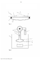
[0047] A figura 1 é uma seção transversal através de uma ferramenta para reter pelo menos um painel de vidro por meio de um efeito de sucção,[0047] Figure 1 is a cross section through a tool to retain at least one pane of glass by means of a suction effect,
[0048] A figura 2 uma seção transversal através de uma modalidade do dispositivo de flexão de vidro de acordo com a invenção com a ferramenta,[0048] Figure 2 is a cross section through an embodiment of the glass bending device according to the invention with the tool,
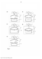
[0049] A figura 3 uma representação em etapas de uma modalidade do método de acordo com a invenção, e[0049] Figure 3 is a representation in stages of an embodiment of the method according to the invention, and
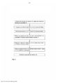
[0050] A figura 4 um fluxograma de uma modalidade do método de acordo com a invenção.[0050] Figure 4 is a flowchart of an embodiment of the method according to the invention.
[0051] A figura 1 representa uma ferramenta 1 conhecida per se para reter pelo menos um painel de vidro por meio de um efeito de sucção (ferramenta de retenção). A ferramenta 1 é um molde superior que é apropriado para reter dois painéis de vidro I, II que se encontram um sobre o outro contra uma superfície de contato convexa semelhante a quadro 2 por meio de um efeito de sucção contra o efeito de gravidade. A superfície de contato 2 está disposta sobre um assim chamado esqueleto 13. Para produzir o efeito de sucção, a ferramenta 1 tem um tubo de sucção 12, através do qual o ar é exaurido. A ferramenta possui ainda uma cobertura 3, cuja extremidade está equipada com uma placa periférica de guia de ar 4. A placa de guia de ar 4 circunda perifericamente a superfície de contato 2. Por meio do esqueleto de flexão 13 e da cobertura 3 com a placa de guia de ar 4, o fluxo de ar produzido pelo tubo de sucção 12 é roteado de modo a varrer as bordas dos painéis de vidro. Assim, o par de painéis de vidro I, II é retido de forma confiável contra a superfície de contato 2.[0051] Figure 1 represents a tool 1 known per se to retain at least one glass panel by means of a suction effect (retention tool). Tool 1 is an upper mold which is suitable for retaining two glass panels I, II lying one on top of the other against a convex contact surface similar to frame 2 by means of a suction effect against the effect of gravity. The contact surface 2 is arranged on a so-called
[0052] Os painéis I, II são pré-flexionados, por exemplo, através de flexão por gravidade em um molde de flexão inferior. A ferramenta descrita pode ser usada, por exemplo, para retirar o par de painéis de vidro I, II para fora do molde inferior e transferi-lo para outro molde. Por exemplo, o par de painéis de vidro I, II pode ser submetido a um processo de flexão por prensa, em que ele é moldado entre a ferramenta representada e um contramolde sob a influência do efeito de pressão e / ou de sucção.[0052] Panels I, II are pre-flexed, for example, by gravity bending in a lower bending mold. The tool described can be used, for example, to take the pair of glass panels I, II out of the lower mold and transfer it to another mold. For example, the pair of glass panels I, II can be subjected to a press bending process, in which it is molded between the depicted tool and a countermold under the influence of the effect of pressure and/or suction.
[0053] A ferramenta apresentada e o método de flexão em que pode ser usado são conhecidos a partir dos documentos EP 1 836 136 B1, WO 2012/080071 A1 e WO 2012/080072 A1.[0053] The tool shown and the bending method in which it can be used are known from EP 1 836 136 B1 , WO 2012/080071 A1 and WO 2012/080072 A1 .
[0054] A figura 2 representa um dispositivo de flexão de vidro de acordo com a invenção que inclui a ferramenta 1 da figura 1 conhecida per se em uma câmara de flexão 8. A câmara de flexão 8 pode ser aquecida por meio de um dispositivo de aquecimento (não mostrado) a uma temperatura acima da temperatura de amolecimento dos painéis a serem flexionados. O dispositivo inclui um molde de flexão por gravidade 9 montado de forma móvel sobre um carrinho, no qual o par de painéis de vidro I, II foi transportado na situação representada e pré-flexionado através de flexão por gravidade. Nos descrito, o par de painéis de vidro I, II foi retirado pela ferramenta 1 e fixado de forma confiável contra ele pelo efeito de sucção.[0054] Figure 2 represents a glass bending device according to the invention that includes the tool 1 of Figure 1 known per se in a
[0055] O efeito de sucção requerido é causado por uma corrente de ar L, que é produzida de acordo com a invenção por um ventilador 5, que está disposto acima da câmara de flexão 8. O ventilador 5 exauri o ar da câmara de flexão 8 através da ferramenta 1 e da linha de alimentação 6 conectada a ele. A linha de alimentação 6 é conectada ao tubo de sucção acima descrito da ferramenta 1. O fluxo de ar L é guiado de volta para a câmara de flexão 8 através de uma linha de retorno 7 e, de fato, no topo da câmara de flexão 8. A linha de alimentação 6 é provida com uma aba 14 por meio da qual a resistência do fluxo de ar L pode ser regulada e o fluxo de ar L pode ser interrompido, sem alterar a velocidade de uma revolução do ventilador 5.[0055] The required suction effect is caused by an air stream L, which is produced according to the invention by a
[0056] O circuito de acordo com a invenção que consiste na linha de alimentação 6, no ventilador 5 e na linha de retorno 7 para produzir o fluxo de ar L permite uma economia de energia significativa. É possível dispensar os bicos de Venturi dispendiosos operados com ar comprimido preaquecido. Por meio da recirculação do ar, pouca energia é desviada para fora do sistema. A compressão do ar por meio do ventilador 5 resulta em um aquecimento que compensa substancialmente o arrefecimento do ar fora da câmara de flexão 8, de modo que o circuito não precisa ser equipado com um dispositivo de aquecimento separado. Ao introduzir o ar no topo da câmara de flexão 8, pelo qual os painéis de vidro I, II não são impactados pelo fluxo de ar L que flui de volta, a influência no processo de flexão é insignificante - a flexão de vidro não é interferida. Estas são as principais vantagens da invenção.[0056] The circuit according to the invention consisting of the
[0057] A figura 3 representa esquematicamente as etapas de uma modalidade do método de acordo com a invenção. Em primeiro lugar, dois painéis de vidro I, II que se encontram um em cima do outro, que são planos no estado inicial, são posicionados em um molde de flexão por gravidade 9 e transportados para ele na câmara de flexão. Os painéis de vidro I, II são aquecidos até a temperatura de flexão, por exemplo, 600 °C, de modo que se aninhem sob o efeito da gravidade contra o molde de flexão por gravidade 9. O aquecimento é feito, por exemplo, em um forno de túnel, que é parte da câmara de flexão 8 ou está situado a montante da mesma. Dentro da câmara de flexão 8, os painéis de vidro pré-flexionados I, II são posicionados no molde de flexão por gravidade 9 abaixo da ferramenta 1 para reter os painéis de vidro I, II (Parte a). A ferramenta 1 é abaixada e a aba 14 é então aberta, pelo que o efeito de sucção atua nos painéis de vidro I, II, que são então levantados com a ferramenta 1 pelo molde de flexão por gravidade 9 (Parte b). Em seguida, um molde de flexão inferior de superfície total 10 é posicionado sob a ferramenta 1. O molde de flexão de sucção 10 pode, por exemplo, ser montado sobre um braço e ser retraído entre a ferramenta 1 e o molde de flexão por gravidade 9. Os painéis de vidro I, II são flexionados na sua forma final entre a ferramenta 1 e o molde de flexão por sucção 10 através de flexão por prensa (Parte c). Durante a flexão por prensa, o efeito de sucção da ferramenta superior 1 é desligado. Após a flexão por prensa, os painéis de vidro I, II são retirados novamente pela ferramenta 1. O molde de flexão por sucção 10 é então deslocado de novo e os painéis de vidro I, II são colocados pela ferramenta 1 sobre um molde de flexão por gravidade 9 (Parte d, e). Os painéis de vidro I, II são transportados para fora do forno de flexão 8 sobre este molde de flexão por gravidade 9 e arrefecidos.[0057] Figure 3 schematically represents the steps of an embodiment of the method according to the invention. First, two glass panels I, II lying on top of each other, which are flat in the initial state, are positioned in a
[0058] As etapas do processo apresentadas esquematicamente aqui refletem o método descrito em maior detalhe no documento EP 1 836 136 B1, em que o dispositivo de flexão de vidro usado para produzir o fluxo de ar L foi suplementado pelo circuito constituído pela linha de alimentação 6, o ventilador 5 e a linha de retorno 7.[0058] The process steps schematically presented here reflect the method described in greater detail in EP 1 836 136 B1, in which the glass bending device used to produce the air flow L was supplemented by the circuit constituted by the
[0059] A figura 4 representa a modalidade exemplar da figura 3 com referência a um fluxograma.[0059] Figure 4 represents the exemplary embodiment of figure 3 with reference to a flowchart.
[0060] Lista de caracteres de referência: (1) ferramenta para reter pelo menos um painel de vidro (2) superfície de contato semelhante a quadro (3) cobertura (4) placa de guia de ar (5) ventilador (6) linha de alimentação (7) linha de retorno (8) câmara de flexão (9) molde de flexão por gravidade (10) molde de flexão inferior (12) tubo de sucção de 1 (13) esqueleto de 1 (14) aba de 6 (L) fluxo de ar (I) Painel de vidro (II) Painel de vidro[0060] List of reference characters: (1) tool to retain at least one pane of glass (2) frame-like contact surface (3) cover (4) air guide plate (5) fan (6) line feed line (7) return line (8) bending chamber (9) gravity bending mold (10) lower bending mold (12) 1 suction tube (13) 1 frame (14) 6 flange ( L) air flow (I) Glass panel (II) Glass panel
Claims (15)
Applications Claiming Priority (3)
| Application Number | Priority Date | Filing Date | Title |
|---|---|---|---|
| EP15181395.3 | 2015-08-18 | ||
| EP15181395 | 2015-08-18 | ||
| PCT/EP2016/069317 WO2017029252A1 (en) | 2015-08-18 | 2016-08-15 | Glass-bending device and glass-bending method using a fan |
Publications (2)
| Publication Number | Publication Date |
|---|---|
| BR112017028325A2 BR112017028325A2 (en) | 2018-09-11 |
| BR112017028325B1 true BR112017028325B1 (en) | 2022-07-05 |
Family
ID=53938161
Family Applications (1)
| Application Number | Title | Priority Date | Filing Date |
|---|---|---|---|
| BR112017028325-5A BR112017028325B1 (en) | 2015-08-18 | 2016-08-15 | GLASS BENDING DEVICE AND GLASS BENDING METHOD USING A FAN |
Country Status (15)
| Country | Link |
|---|---|
| US (1) | US11261120B2 (en) |
| EP (1) | EP3337769B1 (en) |
| JP (1) | JP6498354B2 (en) |
| KR (1) | KR102054730B1 (en) |
| CN (1) | CN106612615B (en) |
| BR (1) | BR112017028325B1 (en) |
| CA (1) | CA2992391C (en) |
| ES (1) | ES2720002T3 (en) |
| MX (1) | MX2018001948A (en) |
| PE (1) | PE20180761A1 (en) |
| PL (1) | PL3337769T3 (en) |
| PT (1) | PT3337769T (en) |
| RU (1) | RU2677509C1 (en) |
| TR (1) | TR201907402T4 (en) |
| WO (1) | WO2017029252A1 (en) |
Families Citing this family (10)
| Publication number | Priority date | Publication date | Assignee | Title |
|---|---|---|---|---|
| PT3212584T (en) | 2014-10-28 | 2019-03-01 | Saint Gobain | Bending tool for glass panes |
| FR3029454B1 (en) * | 2014-12-04 | 2020-09-25 | Saint Gobain | ARMORED WINDOWS MANUFACTURED FROM LARGE SERIES LEAF WINDOWS CONSTITUENTS |
| JP6498354B2 (en) | 2015-08-18 | 2019-04-10 | サン−ゴバン グラス フランスSaint−Gobain Glass France | Glass bending apparatus and glass bending method using blower |
| EA034002B1 (en) | 2015-09-08 | 2019-12-18 | Сэн-Гобэн Гласс Франс | Overpressure-assisted gravity bending method and device suitable therefor |
| CN107614445B (en) | 2015-11-25 | 2020-11-17 | 法国圣戈班玻璃厂 | Overpressure-assisted gravity bending method and device suitable therefor |
| CA2994359C (en) | 2016-01-28 | 2020-01-07 | Gunther Schall | Positive pressure-supported glass bending method and device suitable therefor |
| WO2018122767A1 (en) * | 2016-12-30 | 2018-07-05 | Agp America S.A. | Method and apparatus for bending thin glass |
| CN109206001A (en) * | 2018-09-03 | 2019-01-15 | 郑州福耀玻璃有限公司 | Automobile parts glass rapid prototyping system |
| EP3786576A1 (en) * | 2019-08-26 | 2021-03-03 | Saint-Gobain Glass France | Method and device for measuring the geometry of a curved float glass panel by means of fluorescence radiation after laser excitation |
| US11263120B2 (en) * | 2020-02-12 | 2022-03-01 | Capital One Services, Llc | Feature-based deployment pipelines |
Family Cites Families (141)
| Publication number | Priority date | Publication date | Assignee | Title |
|---|---|---|---|---|
| LU34743A1 (en) | 1956-03-27 | |||
| US3114571A (en) | 1957-10-31 | 1963-12-17 | Libbey Owens Ford Glass Co | Vehicle windshields |
| US3473909A (en) | 1966-12-21 | 1969-10-21 | Corning Glass Works | Method of reshaping glass plates with fluid pressure |
| JPS5130085B1 (en) | 1967-06-19 | 1976-08-30 | ||
| JPS4621038Y1 (en) | 1967-08-21 | 1971-07-20 | ||
| FR2085464B1 (en) | 1970-04-23 | 1974-08-09 | Saint Gobain Pont A Mousson | |
| FR2097019A1 (en) * | 1970-07-28 | 1972-03-03 | Saint Gobain Pont A Mousson | Float glass - lifted over the exit sill by upward aspiration |
| JPS5550897B2 (en) | 1973-02-22 | 1980-12-20 | ||
| US4115090A (en) | 1977-07-28 | 1978-09-19 | Ppg Industries, Inc. | Shaping glass sheets by gravity sagging on solid molds |
| US4233050A (en) | 1979-03-09 | 1980-11-11 | Ppg Industries, Inc. | Shaping glass sheets by gravity sag bending followed by blow forming |
| US4229199A (en) | 1979-05-21 | 1980-10-21 | Ppg Industries, Inc. | Shaping glass sheets by drop forming with differential vacuum release |
| JPS5890604A (en) | 1981-11-25 | 1983-05-30 | Toyota Central Res & Dev Lab Inc | Infrared-ray shielding laminate |
| JPS58209549A (en) | 1982-06-01 | 1983-12-06 | 株式会社豊田中央研究所 | Heat-wave shielding laminate |
| US4511386A (en) * | 1983-05-24 | 1985-04-16 | Ppg Industries, Inc. | Deformable vacuum holder used to shape glass sheets |
| FR2567508B1 (en) * | 1984-07-13 | 1986-11-14 | Saint Gobain Vitrage | METHOD AND DEVICE FOR THE BOMBING OF GLASS PLATES IN A HORIZONTAL POSITION |
| JPS61121002A (en) | 1984-11-17 | 1986-06-09 | Nissan Motor Co Ltd | Light shielding plate |
| JPS61127628A (en) | 1984-11-26 | 1986-06-14 | Nippon Sheet Glass Co Ltd | Forming die for glass |
| US4666492A (en) | 1985-12-11 | 1987-05-19 | Ppg Industries, Inc. | Method and apparatus for shaping glass sheets |
| IE59803B1 (en) * | 1986-03-14 | 1994-04-06 | Glasstech Inc | Glass sheet press bending system |
| FR2596751B1 (en) * | 1986-04-08 | 1988-06-03 | Saint Gobain Vitrage | GLASS FORMING DEVICE |
| DE3615225A1 (en) | 1986-05-06 | 1987-11-12 | Ver Glaswerke Gmbh | METHOD FOR BENDING A PAIR OF GLASS DISC FOR THE PRODUCTION OF A COMPOSITE GLASS DISC |
| FR2601667B1 (en) * | 1986-07-16 | 1988-09-16 | Saint Gobain Vitrage | POSITIONING THE GLASS PLATES FOR THEIR BOMBING |
| FR2601668A1 (en) * | 1986-07-16 | 1988-01-22 | Saint Gobain Vitrage | IMPROVEMENT IN THE BOMBAGE OF GLASS PLATES |
| JPS6327443U (en) | 1986-08-08 | 1988-02-23 | ||
| DE3632556C1 (en) | 1986-09-25 | 1988-02-04 | Ver Glaswerke Gmbh | Method and device for bending a glass sheet |
| GB8624825D0 (en) | 1986-10-16 | 1986-11-19 | Glaverbel | Vehicle windows |
| DE3640892A1 (en) * | 1986-11-29 | 1988-06-09 | Ver Glaswerke Gmbh | METHOD AND DEVICE FOR BENDING A GLASS DISC |
| DE3715151A1 (en) * | 1987-05-07 | 1988-11-17 | Ver Glaswerke Gmbh | METHOD AND DEVICES FOR BENDING GLASS PANES |
| DE3930414C2 (en) | 1989-09-12 | 2002-01-10 | Saint Gobain Sekurit D Gmbh | Method and device for producing a glass pane provided for direct gluing to the fastening flange of a window opening |
| US4877437A (en) | 1988-04-29 | 1989-10-31 | Glasstech International L.P. | Vacuum platen for sharp bends |
| FI81331C (en) * | 1988-11-24 | 1990-10-10 | Tamglass Oy | VAERMEOEVERFOERINGSFOERFARANDE I EN BOEJNINGSUGN FOER GLASSKIVOR OCH EN BOEJNINGSUGN. |
| US4952227A (en) | 1989-05-22 | 1990-08-28 | Libbey-Owens-Ford Co. | Apparatus for processing glass |
| RU2036861C1 (en) | 1989-05-22 | 1995-06-09 | Либбей-Оуэнс-Форд Компани | Device for treatment of glass sheets |
| US5061568A (en) | 1989-12-20 | 1991-10-29 | Monsanto Company | Solar screening assembly |
| FI84805C (en) * | 1990-03-30 | 1992-01-27 | Tamglass Oy | Method and molding device for bending difficult shapes on a glass sheet |
| FI84806C (en) * | 1990-03-30 | 1992-01-27 | Tamglass Oy | Bending or supporting form for glass sheets |
| KR0185750B1 (en) * | 1990-05-22 | 1999-05-01 | 케너드 에이치.웨트모어 | Vacuum impulse forming of heated glass sheets |
| FR2662686B1 (en) | 1990-06-01 | 1992-08-21 | Saint Gobain Vitrage Int | METHOD AND DEVICE FOR BOMBING GLASS SHEETS. |
| FI86054C (en) * | 1990-07-05 | 1992-07-10 | Tamglass Oy | Method and apparatus for bending glass sheet |
| DE4034600C1 (en) * | 1990-10-31 | 1992-02-20 | Vegla Vereinigte Glaswerke Gmbh, 5100 Aachen, De | |
| DE4104086C1 (en) | 1991-02-11 | 1992-02-20 | Vegla Vereinigte Glaswerke Gmbh, 5100 Aachen, De | |
| US5318830A (en) | 1991-05-29 | 1994-06-07 | Central Glass Company, Limited | Glass pane with reflectance reducing coating |
| FR2677015B1 (en) | 1991-05-30 | 1993-08-13 | Saint Gobain Vitrage Int | COATING FOR ANNULAR BOMBING / TEMPERING MOLDS. |
| FR2678261B1 (en) * | 1991-06-27 | 1994-10-21 | Saint Gobain Vitrage Int | METHOD AND DEVICE FOR BOMBING A GLASS SHEET. |
| JP3185934B2 (en) * | 1991-09-04 | 2001-07-11 | 日本板硝子株式会社 | Sheet glass bending method |
| JP3139788B2 (en) | 1991-09-04 | 2001-03-05 | 日本板硝子株式会社 | Sheet glass bending apparatus and bending method |
| TW219953B (en) | 1991-09-30 | 1994-02-01 | Ppg Industries Inc | |
| FI91061C (en) * | 1992-05-27 | 1994-05-10 | Tamglass Eng Oy | Compression bending method and apparatus for bending glass sheets |
| FR2692252B1 (en) | 1992-06-10 | 1994-12-02 | Saint Gobain Vitrage Int | Method for treating glazing and glazing ready to be mounted by gluing in a bay. |
| US5443673A (en) | 1992-06-12 | 1995-08-22 | Donnelly Corporation | Vehicular panel assembly and method for making same |
| FR2693452B1 (en) * | 1992-07-09 | 1994-09-02 | Saint Gobain Vitrage Int | Method and device for supporting and transferring glass sheets in a forming cell. |
| DE4232554C1 (en) | 1992-09-29 | 1994-01-05 | Ver Glaswerke Gmbh | Method for producing a glass pane provided with a molded frame made of a thermoplastic polymer and device for carrying out the method |
| JPH06256030A (en) | 1993-03-02 | 1994-09-13 | Nippon Sheet Glass Co Ltd | Bending of sheet glass |
| FR2707283B1 (en) | 1993-07-09 | 1995-09-22 | Saint Gobain Vitrage Int | Method and device for forming glass plates and application of this method to obtaining glazings of complex shapes. |
| DE4334213A1 (en) * | 1993-10-07 | 1995-04-13 | Ver Glaswerke Gmbh | Method and device for bending glass panes |
| DE4337559C1 (en) * | 1993-11-04 | 1995-03-23 | Ver Glaswerke Gmbh | Process for bending glass sheets in pairs |
| GB9407610D0 (en) | 1994-04-15 | 1994-06-08 | Pilkington Glass Ltd | Bending and tempering glass sheets |
| FR2725194B1 (en) | 1994-10-04 | 1996-10-31 | Saint Gobain Vitrage | METHOD AND DEVICE FOR THE BOMBING OF GLASS SHEETS |
| US5669952A (en) | 1994-10-14 | 1997-09-23 | Ppg Industries, Inc. | Pressure forming of glass sheets |
| GB2300906B (en) * | 1995-05-18 | 1998-11-04 | Stein Atkinson Strody Ltd | Oven for glass article |
| JP4012993B2 (en) * | 1996-01-30 | 2007-11-28 | 旭硝子株式会社 | Sheet glass bending apparatus and method |
| DE19604397C1 (en) | 1996-02-07 | 1997-07-31 | Sekurit Saint Gobain Deutsch | Device for extruding a frame-like profile strand onto a glass pane |
| US5938810A (en) | 1996-10-23 | 1999-08-17 | Donnelly Corporation | Apparatus for tempering and bending glass |
| US5833729A (en) | 1996-12-16 | 1998-11-10 | Ppg Industries, Inc. | Method and apparatus for bending glass sheets |
| DE19719543C1 (en) | 1997-05-09 | 1998-11-19 | Ver Glaswerke Gmbh | Low-E layer system for glass panes |
| US6076373A (en) | 1997-06-16 | 2000-06-20 | Ppg Industries Ohio, Inc. | Apparatus and method for bending glass sheets |
| PL189225B1 (en) | 1997-07-24 | 2005-07-29 | Saint Gobain Vitrage | Vehicle windscreen constituting simultaneously a reflector |
| DE19848373C2 (en) * | 1998-10-21 | 2000-12-07 | Sekurit Saint Gobain Deutsch | Method and device for bending glass sheets with a flat bending shape |
| DE19852358C1 (en) | 1998-11-13 | 2000-05-25 | Ver Glaswerke Gmbh | Low-E coating system with high thermal resistance |
| US6572990B1 (en) | 1998-11-30 | 2003-06-03 | Asahi Glass Company, Limited | Transportation equipment window antireflection film, glass with antireflection film, laminated glass and production method therefor |
| US6365284B1 (en) | 1999-06-04 | 2002-04-02 | Crown Operations International, Ltd. | Flexible solar-control laminates |
| US6309755B1 (en) | 1999-06-22 | 2001-10-30 | Exatec, Llc. | Process and panel for providing fixed glazing for an automotive vehicle |
| BE1012766A3 (en) | 1999-06-30 | 2001-03-06 | Glaverbel | In particular for motor glass roof. |
| MY126647A (en) | 1999-07-23 | 2006-10-31 | Nippon Sheet Glass Co Ltd | Curved glass sheet for vehicle window |
| FR2799005B1 (en) | 1999-09-23 | 2003-01-17 | Saint Gobain Vitrage | GLAZING PROVIDED WITH A STACK OF THIN FILMS ACTING ON THE SOLAR RADIATION |
| FR2818272B1 (en) | 2000-12-15 | 2003-08-29 | Saint Gobain | GLAZING PROVIDED WITH A STACK OF THIN FILMS FOR SUN PROTECTION AND / OR THERMAL INSULATION |
| DE10105200A1 (en) | 2001-02-06 | 2002-08-14 | Saint Gobain | Method and device for bending glass sheets in pairs |
| US6602371B2 (en) | 2001-02-27 | 2003-08-05 | Guardian Industries Corp. | Method of making a curved vehicle windshield |
| US6543255B2 (en) | 2001-06-19 | 2003-04-08 | Glasstech, Inc. | Press bending station and method for job switching |
| JP3572300B2 (en) | 2001-08-03 | 2004-09-29 | 三菱重工業株式会社 | Aircraft window made of synthetic resin with hard film |
| FR2829723B1 (en) | 2001-09-14 | 2004-02-20 | Saint Gobain | FUNCTIONALIZED SAFETY GLASS |
| EP1484290B1 (en) | 2002-03-13 | 2010-09-08 | Asahi Glass Company Ltd. | Method of bend molding glass plate and apparatus |
| US7231787B2 (en) | 2002-03-20 | 2007-06-19 | Guardian Industries Corp. | Apparatus and method for bending and/or tempering glass |
| US20030182969A1 (en) | 2002-03-28 | 2003-10-02 | Dunifon Thomas A. | Glass handling and locating system |
| FI20021131A (en) | 2002-06-12 | 2003-12-13 | Tamglass Ltd Oy | Device for bending and hardening of glass sheets |
| FR2852951B1 (en) | 2003-03-26 | 2007-02-16 | Saint Gobain | METHOD FOR BOMBING GLASS SHEETS BY PRESSING AND SUCTION |
| DE10314266B3 (en) | 2003-03-29 | 2004-06-09 | Saint-Gobain Sekurit Deutschland Gmbh & Co. Kg | Process for bending glass panes comprises placing the panes on a concave bending frame mold and pre-bending under gravitational force, transferring to a delivery mold, and further processing |
| FR2855168B1 (en) | 2003-05-19 | 2007-03-30 | Saint Gobain | GRAVITY GLAZING OVER MULTIPLE MEDIA |
| US7943246B2 (en) | 2003-07-11 | 2011-05-17 | Pilkington Group Limited | Solar control glazing |
| CN2641043Y (en) | 2003-07-29 | 2004-09-15 | 洛阳北方玻璃技术股份有限公司 | Glass lifting negative pressure mould loader in bend toughened glasls prodn. equipment |
| US20050238923A1 (en) | 2004-04-27 | 2005-10-27 | Thiel James P | Hybrid coating stack |
| GB0423085D0 (en) | 2004-10-18 | 2004-11-17 | Pilkington Automotive Ltd | Solar control glazing |
| FR2880343B1 (en) | 2004-12-31 | 2007-06-22 | Saint Gobain | PROCESS FOR BOMBING GLASS SHEETS BY SUCTION |
| DE102005001513B3 (en) | 2005-01-13 | 2006-06-01 | Saint-Gobain Sekurit Deutschland Gmbh & Co. Kg | Process and assembly to manufacture curved automotive windscreens passing through oven on two-part trolley mould train |
| BE1016542A3 (en) | 2005-03-10 | 2007-01-09 | Glaverbel | Method and device for bending glass sheets. |
| JP5147034B2 (en) | 2005-03-17 | 2013-02-20 | 独立行政法人産業技術総合研究所 | Automatic thermal color-harmonic shading glass and manufacturing method |
| DE102005039707B4 (en) | 2005-08-23 | 2009-12-03 | Saint-Gobain Glass Deutschland Gmbh | Highly resilient low-E coating system for transparent substrates, especially for glass panes |
| ITRM20060181A1 (en) | 2006-03-31 | 2007-10-01 | Pilkington Italia Spa | GLAZED GLASS SHEET |
| US20090117371A1 (en) | 2006-04-07 | 2009-05-07 | Interpane Entwicklungs-Und Beratungsgesellschaft Mbh & Co. Kg | Weather-resistant layer system |
| KR101334945B1 (en) | 2006-11-02 | 2013-11-29 | 삼성디스플레이 주식회사 | Alignment Layer and Liquid Crystal Display Apparatus Having the Same |
| WO2008080072A2 (en) | 2006-12-22 | 2008-07-03 | Petroradiant Inc. | Radiation processing of heavy oils |
| US7655313B2 (en) | 2007-03-15 | 2010-02-02 | Guardian Industries Corp. | Low-E coated articles and methods of making same |
| US7975509B2 (en) | 2007-06-27 | 2011-07-12 | Pilkington North America, Inc. | Glass bending process |
| EP2233444B1 (en) | 2007-12-04 | 2013-02-20 | Asahi Glass Company, Limited | Glass pane bending and forming method, and glass pane bending and forming appratus |
| DE102007059323A1 (en) | 2007-12-07 | 2009-06-10 | Saint-Gobain Sekurit Deutschland Gmbh & Co. Kg | Curved windscreen for motor vehicle, has outer and inner glass surfaces with wedge angle that is changed from lower edge upto upper edge of field of vision to compensate double images in each point on vertical center line of field of vision |
| WO2009071135A1 (en) | 2007-12-07 | 2009-06-11 | Saint-Gobain Glass France | Curved vehicle windshield made from laminated glass |
| EP2233443B1 (en) | 2007-12-28 | 2013-07-03 | Asahi Glass Company, Limited | Glass-pane shaping-heating apparatus, and glass-pane bending-shaping method |
| FR2927897B1 (en) | 2008-02-27 | 2011-04-01 | Saint Gobain | ANTISOLAR GLAZING HAVING IMPROVED LUMINOUS TRANSMISSION COEFFICIENT. |
| DE112009001131A5 (en) | 2008-05-12 | 2011-09-22 | Arizona Board Of Regents, On Behalf Of The University Of Arizona | Method for producing large parabolic dish reflectors for a solar concentrator device |
| FR2931147B1 (en) | 2008-05-19 | 2010-11-19 | Saint Gobain | GLAZING PROVIDED WITH A STACK OF THIN LAYERS |
| DE102008030825A1 (en) | 2008-06-30 | 2009-12-31 | Schott Ag | Device for reflecting heat radiation, a method for its production and its use |
| WO2010074548A1 (en) | 2008-12-22 | 2010-07-01 | Vidrio Plano De Mexico, Sa De Cv | Method and system for bending sheets of glass with complex curves |
| EP2236534A1 (en) | 2009-03-31 | 2010-10-06 | Sika Technology AG | Composition curable in two stages comprising a surface deactivated polyisocyanate |
| FR2945985B1 (en) | 2009-05-27 | 2011-05-20 | Saint Gobain | GLAZING WITH LOW LEVEL OF DOUBLE IMAGE. |
| CN101875536B (en) | 2009-12-31 | 2013-06-12 | 中航三鑫股份有限公司 | Coated glass and manufacture method thereof |
| CA2786872A1 (en) | 2010-01-16 | 2011-07-21 | Cardinal Cg Company | High quality emission control coatings, emission control glazings, and production methods |
| PL3141534T3 (en) | 2010-02-26 | 2019-10-31 | Guardian Glass Llc | Articles including anticondensation and/or low-e coatings and/or methods of making the same |
| FR2960232B1 (en) | 2010-05-19 | 2015-01-02 | Saint Gobain | ALVEOLAR BOMBING SHAPE |
| FR2963343B1 (en) | 2010-07-28 | 2012-07-27 | Saint Gobain | GLAZING WITH COATING AGAINST CONDENSATION |
| RU2444478C1 (en) | 2010-08-31 | 2012-03-10 | Федеральное государственное унитарное предприятие "Обнинское научно-производственное предприятие "Технология" | Method of bending sheet glass |
| EP2463247A1 (en) | 2010-12-13 | 2012-06-13 | Saint-Gobain Glass France | Method and device for bending discs |
| MX344209B (en) | 2010-12-13 | 2016-12-08 | Saint Gobain | Bent windowpane. |
| EP2463248A1 (en) | 2010-12-13 | 2012-06-13 | Saint-Gobain Glass France | Method and device for bending sheets |
| WO2012118612A1 (en) | 2011-02-28 | 2012-09-07 | Corning Incorporated | Method of forming a 3d glass article from a 2d glass sheet |
| FR2973023B1 (en) | 2011-03-25 | 2019-08-02 | Saint-Gobain Glass France | MULTIPLE INSULATION GLAZING COMPRISING TWO LOW EMISSIVE STACKS |
| ES2854986T3 (en) | 2012-03-05 | 2021-09-23 | Saint Gobain | Car window with thermal radiation reflective coating |
| EP2639032B1 (en) | 2012-03-13 | 2014-09-24 | Saint-Gobain Glass France | Method for bonding coated laminated compound glazing |
| US8962084B2 (en) | 2012-05-31 | 2015-02-24 | Corning Incorporated | Methods of applying a layer of material to a non-planar glass sheet |
| JP6012887B2 (en) | 2013-02-20 | 2016-10-25 | サン−ゴバン グラス フランス | Sheet glass with thermal radiation reflective coating |
| JP6181210B2 (en) | 2013-02-20 | 2017-08-16 | サン−ゴバン グラス フランス | Sheet glass with thermal radiation reflective coating |
| KR101343631B1 (en) | 2013-02-26 | 2013-12-18 | 코리아 오토글라스 주식회사 | Apparatus and method for forming glass sheets |
| EP2984048B1 (en) | 2013-04-09 | 2018-09-05 | NV Bekaert SA | Heat resistant woven tape |
| RU2550611C1 (en) * | 2014-03-05 | 2015-05-10 | Закрытое акционерное общество "МАКРОМЕР" | Plate glass bending unit |
| MX2017005445A (en) | 2014-10-28 | 2017-06-29 | Saint Gobain | Tool for a glass-bending process. |
| PT3212584T (en) | 2014-10-28 | 2019-03-01 | Saint Gobain | Bending tool for glass panes |
| CN106457778B (en) | 2015-05-15 | 2018-03-30 | 法国圣戈班玻璃厂 | With heat radiation reflectance coating and the glass plate of fixation mounted thereto or potted component |
| GB2538559B (en) | 2015-05-22 | 2020-02-12 | William Blythe Ltd | Provision of inorganic powders with reduced hazard |
| JP6498354B2 (en) | 2015-08-18 | 2019-04-10 | サン−ゴバン グラス フランスSaint−Gobain Glass France | Glass bending apparatus and glass bending method using blower |
| EA034002B1 (en) | 2015-09-08 | 2019-12-18 | Сэн-Гобэн Гласс Франс | Overpressure-assisted gravity bending method and device suitable therefor |
| CN107614445B (en) | 2015-11-25 | 2020-11-17 | 法国圣戈班玻璃厂 | Overpressure-assisted gravity bending method and device suitable therefor |
| CA2994359C (en) * | 2016-01-28 | 2020-01-07 | Gunther Schall | Positive pressure-supported glass bending method and device suitable therefor |
-
2016
- 2016-08-15 JP JP2018508694A patent/JP6498354B2/en active Active
- 2016-08-15 BR BR112017028325-5A patent/BR112017028325B1/en active IP Right Grant
- 2016-08-15 CN CN201680001771.XA patent/CN106612615B/en active Active
- 2016-08-15 KR KR1020187004170A patent/KR102054730B1/en active IP Right Grant
- 2016-08-15 RU RU2018109372A patent/RU2677509C1/en active
- 2016-08-15 EP EP16757190.0A patent/EP3337769B1/en active Active
- 2016-08-15 PE PE2018000254A patent/PE20180761A1/en unknown
- 2016-08-15 ES ES16757190T patent/ES2720002T3/en active Active
- 2016-08-15 CA CA2992391A patent/CA2992391C/en not_active Expired - Fee Related
- 2016-08-15 TR TR2019/07402T patent/TR201907402T4/en unknown
- 2016-08-15 PT PT16757190T patent/PT3337769T/en unknown
- 2016-08-15 US US15/741,264 patent/US11261120B2/en active Active
- 2016-08-15 PL PL16757190T patent/PL3337769T3/en unknown
- 2016-08-15 MX MX2018001948A patent/MX2018001948A/en unknown
- 2016-08-15 WO PCT/EP2016/069317 patent/WO2017029252A1/en active Application Filing
Also Published As
| Publication number | Publication date |
|---|---|
| CN106612615B (en) | 2021-04-02 |
| PE20180761A1 (en) | 2018-05-03 |
| TR201907402T4 (en) | 2019-06-21 |
| PL3337769T3 (en) | 2019-09-30 |
| CA2992391C (en) | 2019-12-31 |
| EP3337769A1 (en) | 2018-06-27 |
| ES2720002T3 (en) | 2019-07-17 |
| EP3337769B1 (en) | 2019-04-03 |
| US20180194664A1 (en) | 2018-07-12 |
| WO2017029252A1 (en) | 2017-02-23 |
| US11261120B2 (en) | 2022-03-01 |
| MX2018001948A (en) | 2018-06-19 |
| RU2677509C1 (en) | 2019-01-17 |
| JP6498354B2 (en) | 2019-04-10 |
| KR20180028506A (en) | 2018-03-16 |
| JP2018528149A (en) | 2018-09-27 |
| KR102054730B1 (en) | 2019-12-11 |
| CA2992391A1 (en) | 2017-02-23 |
| CN106612615A (en) | 2017-05-03 |
| BR112017028325A2 (en) | 2018-09-11 |
| PT3337769T (en) | 2019-06-07 |
Similar Documents
| Publication | Publication Date | Title |
|---|---|---|
| BR112017028325B1 (en) | GLASS BENDING DEVICE AND GLASS BENDING METHOD USING A FAN | |
| BR112017001769B1 (en) | Glass panel retention tool, glass panel bending method and tool use | |
| CN203923006U (en) | A kind of toughened glass production line | |
| BR112013013249B1 (en) | method for folding a panel and oven for folding panels using such a method | |
| US4501603A (en) | Method and apparatus for shaping glass sheets to complicated shapes | |
| JP6085894B2 (en) | Preform heating device | |
| BR112017027456B1 (en) | GRAVITY BENDING METHOD AIDED BY OVERPRESSURE, APPROPRIATE DEVICE FOR THE SAME AND USE OF A SUPERIOR FORMING TOOL | |
| BR112017026188B1 (en) | GRAVITY CURVATURE METHOD AID BY OVERPRESSURE AND SUITABLE DEVICE FOR THE SAME | |
| BR112018008794B1 (en) | PROCESSING SYSTEM FOR PROCESSING HOT GLASS SHEET | |
| JPH0662309B2 (en) | Method and device for manufacturing curved glass | |
| JP6912096B2 (en) | Mold shuttle positioning system for glass sheet molding system | |
| CN105293880B (en) | A kind of toughened glass production line | |
| FI89038C (en) | FOER FARING FOR BOARDING AND FURNISHING | |
| JPWO2020162467A1 (en) | Glass plate molding equipment | |
| JP5454205B2 (en) | Glass plate bending apparatus and method | |
| CN105198197B (en) | A kind of toughened glass production line | |
| JP2021533071A (en) | Methods and equipment for bending sheets | |
| KR20200029001A (en) | Method and apparatus for bending plate glass | |
| JP2020528866A (en) | Methods and equipment for bending panes | |
| JPWO2020162468A1 (en) | How to mold a glass plate | |
| CN217227043U (en) | Sphygmomanometer armlet drying device | |
| CN216101021U (en) | Preheating or auxiliary heating system for printing PET film | |
| CN105217938A (en) | The using method of the stove external air cooling system device of mobile phone 3D bend glass cover plate thermoforming stove | |
| TW202325113A (en) | Heating device and oven wherein the heating device includes a base unit and a heating unit |
Legal Events
| Date | Code | Title | Description |
|---|---|---|---|
| B06U | Preliminary requirement: requests with searches performed by other patent offices: procedure suspended [chapter 6.21 patent gazette] | ||
| B09A | Decision: intention to grant [chapter 9.1 patent gazette] | ||
| B16A | Patent or certificate of addition of invention granted [chapter 16.1 patent gazette] |
Free format text: PRAZO DE VALIDADE: 20 (VINTE) ANOS CONTADOS A PARTIR DE 15/08/2016, OBSERVADAS AS CONDICOES LEGAIS |