BR112016017516B1 - CONNECTED ELECTRICAL CONTROL CABINET SYSTEM - Google Patents
CONNECTED ELECTRICAL CONTROL CABINET SYSTEM Download PDFInfo
- Publication number
- BR112016017516B1 BR112016017516B1 BR112016017516-6A BR112016017516A BR112016017516B1 BR 112016017516 B1 BR112016017516 B1 BR 112016017516B1 BR 112016017516 A BR112016017516 A BR 112016017516A BR 112016017516 B1 BR112016017516 B1 BR 112016017516B1
- Authority
- BR
- Brazil
- Prior art keywords
- profile
- frame
- electrical control
- control cabinet
- seal
- Prior art date
Links
Images


Classifications
-
- H—ELECTRICITY
- H02—GENERATION; CONVERSION OR DISTRIBUTION OF ELECTRIC POWER
- H02B—BOARDS, SUBSTATIONS OR SWITCHING ARRANGEMENTS FOR THE SUPPLY OR DISTRIBUTION OF ELECTRIC POWER
- H02B1/00—Frameworks, boards, panels, desks, casings; Details of substations or switching arrangements
- H02B1/26—Casings; Parts thereof or accessories therefor
- H02B1/30—Cabinet-type casings; Parts thereof or accessories therefor
-
- H—ELECTRICITY
- H02—GENERATION; CONVERSION OR DISTRIBUTION OF ELECTRIC POWER
- H02B—BOARDS, SUBSTATIONS OR SWITCHING ARRANGEMENTS FOR THE SUPPLY OR DISTRIBUTION OF ELECTRIC POWER
- H02B1/00—Frameworks, boards, panels, desks, casings; Details of substations or switching arrangements
- H02B1/01—Frameworks
-
- H—ELECTRICITY
- H02—GENERATION; CONVERSION OR DISTRIBUTION OF ELECTRIC POWER
- H02B—BOARDS, SUBSTATIONS OR SWITCHING ARRANGEMENTS FOR THE SUPPLY OR DISTRIBUTION OF ELECTRIC POWER
- H02B1/00—Frameworks, boards, panels, desks, casings; Details of substations or switching arrangements
- H02B1/26—Casings; Parts thereof or accessories therefor
- H02B1/28—Casings; Parts thereof or accessories therefor dustproof, splashproof, drip-proof, waterproof or flameproof
-
- H—ELECTRICITY
- H02—GENERATION; CONVERSION OR DISTRIBUTION OF ELECTRIC POWER
- H02B—BOARDS, SUBSTATIONS OR SWITCHING ARRANGEMENTS FOR THE SUPPLY OR DISTRIBUTION OF ELECTRIC POWER
- H02B1/00—Frameworks, boards, panels, desks, casings; Details of substations or switching arrangements
- H02B1/26—Casings; Parts thereof or accessories therefor
- H02B1/30—Cabinet-type casings; Parts thereof or accessories therefor
- H02B1/303—Bases or feet
-
- H—ELECTRICITY
- H02—GENERATION; CONVERSION OR DISTRIBUTION OF ELECTRIC POWER
- H02B—BOARDS, SUBSTATIONS OR SWITCHING ARRANGEMENTS FOR THE SUPPLY OR DISTRIBUTION OF ELECTRIC POWER
- H02B1/00—Frameworks, boards, panels, desks, casings; Details of substations or switching arrangements
- H02B1/26—Casings; Parts thereof or accessories therefor
- H02B1/30—Cabinet-type casings; Parts thereof or accessories therefor
- H02B1/308—Mounting of cabinets together
-
- H—ELECTRICITY
- H05—ELECTRIC TECHNIQUES NOT OTHERWISE PROVIDED FOR
- H05K—PRINTED CIRCUITS; CASINGS OR CONSTRUCTIONAL DETAILS OF ELECTRIC APPARATUS; MANUFACTURE OF ASSEMBLAGES OF ELECTRICAL COMPONENTS
- H05K7/00—Constructional details common to different types of electric apparatus
- H05K7/14—Mounting supporting structure in casing or on frame or rack
Landscapes
- Engineering & Computer Science (AREA)
- Power Engineering (AREA)
- Microelectronics & Electronic Packaging (AREA)
- Patch Boards (AREA)
- Casings For Electric Apparatus (AREA)
- Switch Cases, Indication, And Locking (AREA)
- Assembled Shelves (AREA)
- Gasket Seals (AREA)
Abstract
sistema de armário de comando elétrico conectado. a presente invenção refere-se a um sistema de armário de comando elétrico, que está formado por unidades de armário de comando elétrico conectadas, sendo que cada unidade de armário de comando elétrico compreende uma estrutura de quadro, que está formada por perfis de quadro, sendo que pelo menos os perfis de quadro verticais apresentam as seguintes características: o perfil de quadro (100, 100'; 200, 200'; 300, 300') está especularmente simétrico, com relação a uma diagonal de secção transversal (d); o perfil de quadro apresenta lados de perfil (111, 112; 211, 212; 311, 312), que formam os lados externos da estrutura de quadro; dos lados de perfil (111,112; 211, 212; 311, 312) saem prolongamentos de perfil (114, 115; 214, 215; 314, 315), que se estendem, em cada caso, afastados dos lados de perfil (111, 112; 211, 212; 311, 312); na conexão de duas estruturas de quadro, estão opostos de modo especularmente simétrico, em cada caso, prolongamentos de perfil (114?, 115; 214?, 215; 314?, 315), correspondentes de dois perfis de quadro, sendo que entre os lados frontais dos prolongamentos de perfil permanece um espaço intermediário, que está fechado por uma vedação (130; 230; 330; 510, 530, 550), caracterizado pelo fato de que a vedação (130; 230; 330) é uma vedação de inserção, assentada sobre pelo menos um dos prolongamentos de perfil (114?, 115; 214?, 215; 314?, 315), opostos um ao outro.connected electrical control cabinet system. The present invention relates to an electrical control cabinet system, which is formed by connected electrical control cabinet units, each electrical control cabinet unit comprising a switchgear structure, which is formed by switchgear profiles, at least the vertical frame profiles have the following characteristics: the frame profile (100, 100'; 200, 200'; 300, 300') is specularly symmetrical with respect to a diagonal of cross section (d); the frame profile has profile sides (111, 112; 211, 212; 311, 312), which form the outer sides of the frame structure; from the profile sides (111, 112; 211, 212; 311, 312) there are profile extensions (114, 115; 214, 215; 314, 315), which in each case extend away from the profile sides (111, 112). ; 211, 212; 311, 312); in the connection of two frame structures, there are specularly symmetrical opposites, in each case, profile extensions (114?, 115; 214?, 215; 314?, 315), corresponding to two frame profiles, being that between the front sides of the profile extensions, an intermediate space remains, which is closed by a seal (130; 230; 330; 510, 530, 550), characterized in that the seal (130; 230; 330) is an insertion seal. , seated on at least one of the profile extensions (114', 115; 214', 215; 314', 315), opposite one another.
Description
[0001] A invenção refere-se a um sistema de armário de comando elétrico, que está formado por unidades de armário de comando elétrico conectadas, sendo que cada unidade de armário de comando elétrico compreende uma estrutura de quadro, que está formada por perfis de quadro, sendo que pelo menos os perfis de quadro verticais apresentam as seguintes características o perfil de quadro é especularmente simétrico; o perfil de quadro apresenta lados de perfil, que formam os lados externos da estrutura de quadro; e dos lados de perfil saem prolongamentos, que, em cada caso, estendem-se afastados dos lados de perfil. Na conexão de duas estruturas de quadro, prolongamentos de perfil correspondentes de dois perfis de quadro estão, em cada caso, opostos simetricamente um ao outro, sendo que entre os lados frontais dos prolongamentos de perfil permanece um espaço intermediário, que está fechado por uma vedação.[0001] The invention relates to an electrical control cabinet system, which is formed by connected electrical control cabinet units, each electrical control cabinet unit comprising a frame structure, which is formed by frame, at least vertical frame profiles having the following characteristics: the frame profile is specularly symmetrical; the frame profile features profile sides, which form the outer sides of the frame structure; and from the profile sides there are extensions which, in each case, extend away from the profile sides. When connecting two frame structures, corresponding profile extensions of two frame profiles are in each case symmetrically opposed to each other, whereby an intermediate space remains between the front sides of the profile extensions, which is closed by a seal. .
[0002] Para armários de comando elétrico a conectividade é um critério importante, uma vez que, desse modo, as possibilidades de uso são ampliadas. Uma unidade de armário de comando elétrico conectável pode ser combinada com outras unidades de armário desse tipo e ser reunido para um sistema de armário de comando elétrico maior, de acordo com o desejo do cliente. Particularmente, esse sistema de armário de comando elétrico modular pode ser adaptado à necessidade de espaço necessário ou disponível. A conectividade também tem a vantagem de que cabos e linhas podem ser instalados internamente para além da unidade de armário de comando elétrico individual. Como em armários conectados as paredes laterais são suprimidas na conexão, por razões de estabilidade é necessária uma estrutura de quadros. A conexão ocorre, portanto, através da estrutura de quadro, sendo que se apresenta o problema da vedação em relação à região externa ou ao entorno. No ponto de conexão são introduzidas, portanto, vedações, para impedir tanto quanto possível a penetração de, por exemplo, poeira ou umidade.[0002] Connectivity is an important criterion for electrical control cabinets, since in this way the possibilities of use are expanded. A pluggable electrical control cabinet unit can be combined with other such cabinet units and merged into a larger electrical control cabinet system as per the customer's wishes. In particular, this modular electrical control cabinet system can be adapted to the need for space required or available. Connectivity also has the advantage that cables and lines can be installed internally in addition to the individual electrical control cabinet unit. As in connected cabinets the side walls are suppressed in the connection, for reasons of stability a frame structure is required. The connection occurs, therefore, through the frame structure, and the problem of sealing in relation to the external region or surroundings is presented. Seals are therefore introduced at the connection point to prevent penetration of, for example, dust or moisture as far as possible.
[0003] Um perfil de quadro de uma estrutura de quadro, que está configurado para uma unidade de armário de comando elétrico conectável, é conhecido do documento EP 1 601 074 b1. No ponto de conexão de dois perfis de quadro opostos um ao outro está inserida uma vedação de tira, que deve completar uma disposição de vedação, que é gerada por dois núcleos externos do perfil, que estão encostados de modo rente um no outro, bem como por uma disposição de conexão, de uma parte de acoplamento, que é comprimida por pinos. A disposição conhecida é complexa e requer diversos passos de montagem.[0003] A switchgear profile of a switchgear structure, which is configured for a pluggable electrical control cabinet unit, is known from EP 1 601 074 b1. A strip seal is inserted at the point of connection of two opposite frame profiles, which must complete a sealing arrangement, which is generated by two external cores of the profile, which are flush against each other, as well as by a connecting arrangement, of a coupling part, which is pin-compressed. The known arrangement is complex and requires several assembly steps.
[0004] É portanto, tarefa da invenção indicar um sistema de armário de comando elétrico, no qual a conexão deve ser realizada, se possível sem ferramentas.[0004] It is therefore the task of the invention to indicate an electrical control cabinet system, in which the connection must be carried out, if possible without tools.
[0005] Essa tarefa é solucionada por um sistema de armário de comando elétrico de acordo com a reivindicação 1. Configurações vantajosas são objeto das reivindicações secundárias.[0005] This task is solved by an electrical control cabinet system according to claim 1. Advantageous configurations are the subject of secondary claims.
[0006] De acordo com a invenção está previsto que a vedação é uma vedação de inserção, assentada sobre pelo menos um dos prolongamentos de perfil opostos dos perfis de quadro. Outras medidas para vedação, em princípio, não precisam ser tomadas, mas podem contribuir para a estabilidade da disposição.[0006] According to the invention, it is provided that the seal is an insert seal, seated on at least one of the opposite profile extensions of the frame profiles. Other sealing measures, in principle, do not need to be taken, but can contribute to the stability of the arrangement.
[0007] De acordo com uma modalidade preferida da invenção está previsto que a vedação de inserção apresenta pelo menos duas seções opostas uma à outra, entre os quais permanece uma fenda, cuja largura é menor ou igual à espessura do prolongamento de perfil do perfil de quadro selecionado. Assim, o prolongamento de perfil é fechado pelo menos com ajuste por fricção, mas também pode ser que, quando a largura da fenda é menor do que a espessura do prolongamento de perfil, fica assegurado por seleção de material apropriada que a vedação de inserção se encoste sob uma determinação tensão própria do material no prolongamento de perfil.[0007] According to a preferred embodiment of the invention, it is provided that the insert seal has at least two sections opposite each other, between which there remains a gap whose width is less than or equal to the thickness of the profile extension of the profile. selected frame. Thus, the profile extension is closed at least with friction fit, but it may also be that when the width of the slot is less than the thickness of the profile extension, it is ensured by appropriate material selection that the insert seal will fit. abutment under a specific stress of the material on the profile extension.
[0008] É preferido, ainda, que a peça de união que conecta as seções opostas da vedação de inserção apresente uma superfície de encosto, que é mais larga do que a espessura do prolongamento de perfil do perfil de quadro a ser ali conectado. Por essa medida podem ser compensadas tolerâncias, que podem ocorrer na conexão das filas de armários de comando elétrico. Novamente pela seleção de material pode ser assegurado que o prolongamento de perfil do perfil de quadro a ser conectado pode penetrar na peça de união de conexão, de modo que existe um cuidado para que haja um fecho hermético para poeira ou umidade, também na estrutura de quadro a ser conectada. Essa configuração de uma vedação de inserção também possibilita produzir um sistema de armário de comando elétrico de diferentes estruturas de quadro. Particularmente, a estrutura de quadro a ser conectada não precisa apresentar um prolongamento de perfil configurado de modo especial.[0008] It is further preferred that the joint piece connecting the opposing sections of the insert seal has an abutment surface which is wider than the thickness of the profile extension of the frame profile to be connected thereto. This measure can compensate for tolerances that may occur when connecting rows of electrical control cabinets. Again by the material selection it can be ensured that the profile extension of the frame profile to be connected can penetrate the connecting joint piece, so care is taken to ensure that there is an airtight seal for dust or moisture, also in the frame structure. frame to be connected. This configuration of an insert seal also makes it possible to produce an electrical control cabinet system from different switchgear structures. In particular, the frame structure to be connected does not need to have a specially configured profile extension.
[0009] Pode ainda estar previsto que as seções opostas da vedação de inserção têm um comprimento diferente. Isso facilita aplicar a vedação e inserção sobre o prolongamento de perfil do perfil de quadro selecionado.[0009] It may also be provided that the opposing sections of the insert seal have a different length. This makes it easy to apply the seal and insert over the profile extension of the selected frame profile.
[0010] Também pode estar previsto que as seções opostas uma à outra da vedação de inserção tenham uma largura diferente. Também isso facilita a aplicação da vedação de inserção, uma vez que o material em uma das seções opostas é mais elástico.[0010] It can also be provided that the sections opposite each other of the insert seal have a different width. This also facilitates the application of the insert seal, as the material in one of the opposing sections is more elastic.
[0011] De acordo com uma modalidade preferida da invenção, a vedação de inserção é em forma de H em secção transversal.[0011] According to a preferred embodiment of the invention, the insert seal is H-shaped in cross-section.
[0012] O comprimento das seções da vedação em forma de H pode ser adaptado às circunstâncias e, em geral, deve ser levado em consideração que a inserção sem ferramentas é dificultada se, devido ao comprimento das seções, é preciso superar uma força de fricção elevada. Em conexão com determinados perfis, porém, pode ser vantajoso quando o comprimento das seções da vedação em forma de H corresponde na direção da secção transversal do perfil de quadro, substancialmente, ao comprimento dos prolongamentos de perfil.[0012] The length of the sections of the H-shaped seal can be adapted to the circumstances and, in general, it must be taken into account that insertion without tools is difficult if, due to the length of the sections, a friction force must be overcome. high. In connection with certain profiles, however, it may be advantageous when the length of the H-shaped seal sections corresponds in the direction of the cross-section of the frame profile substantially to the length of the profile extensions.
[0013] Novamente, para facilitar a conexão de uma estrutura de quadro a ser conectada ou a inserção da vedação de inserção sobre o prolongamento de perfil da mesma, pode estar previsto que as seções da vedação e inserção opostas uma à outra formam entre si uma fenda, que partindo da peça de união que conecta as mesmas está alargada para fora.[0013] Again, to facilitate the connection of a frame structure to be connected or the insertion of the insert seal over the profile extension thereof, it can be provided that the sections of the seal and insert opposite to each other form a slit, which, starting from the connecting piece that connects them, is flared outwards.
[0014] Perfis de quadro apropriados têm, por exemplo, prolongamentos de perfil, que se estendem perpendicularmente da respectivo lado de perfil. Outras modalidades estão caracterizadas pelo fato de que os prolongamentos de perfil estendem-se sob um ângulo de aproximadamente 135° à respectiva tira de perfil.[0014] Suitable frame profiles have, for example, profile extensions, which extend perpendicularly from the respective profile side. Other embodiments are characterized by the fact that the profile extensions extend at an angle of approximately 135° to the respective profile strip.
[0015] De preferência, é usado um perfil de câmara oca com pelo menos uma câmara oca, que se distingue por uma boa estabilidade, particularmente, rigidez à torção.[0015] Preferably, a hollow chamber profile is used with at least one hollow chamber, which is distinguished by good stability, particularly torsional rigidity.
[0016] De acordo com uma configuração especial existem duas câmaras ocas, que estão conectados por uma peça de união. Nesse caso, pode estar previsto que entre as duas câmaras ocas, adjacente à peça de união, está formada uma ranhura em forma de cauda de andorinha, simétrica à diagonal de secção transversal. Como alternativa, entre as duas câmaras ocas, pode estar formada uma terceira câmara oca, adjacente à peça de união.[0016] According to a special configuration there are two hollow chambers, which are connected by a joining piece. In that case, it can be provided that between the two hollow chambers, adjacent to the connecting piece, a dovetail-shaped groove is formed, symmetrical to the diagonal of the cross section. Alternatively, between the two hollow chambers, a third hollow chamber may be formed, adjacent to the joining piece.
[0017] Perfis ocos de uma câmara são, por exemplo, retangulares ou quadrados em secção transversal. Em uma variante, pode estar previsto que os lados de perfil compreendem dois segmentos de lado de perfil, passando um para dentro do outro, que estão angulados de tal modo que o primeiro segmento de lado de perfil do primeiro lado de perfil estende-se perpendicularmente ao primeiro segmento de lado de perfil do segundo lado de perfil e o segundo segmento de lado de perfil do primeiro lado de perfil estende-se paralelamente ao segundo segmento de lado de perfil do segundo lado de perfil.[0017] Hollow profiles of a chamber are, for example, rectangular or square in cross section. In a variant, provision can be made for the profile sides to comprise two profile side segments, passing one into the other, which are angled in such a way that the first profile side segment of the first profile side extends perpendicularly. to the first profile side segment of the second profile side and the second profile side segment of the first profile side extends parallel to the second profile side segment of the second profile side.
[0018] A invenção, para conexão de estruturas de quadro do mesmo tipo pode ser usada do mesmo modo como para estruturas de quadro, que usam geometrias de perfil diferentes nos perfis de quadro verticais. Também são concebíveis geometrias de perfil diferentes dentro de uma estrutura de quadro.[0018] The invention, for connecting frame structures of the same type, can be used in the same way as for frame structures, which use different profile geometries in the vertical frame profiles. Different profile geometries are also conceivable within a frame structure.
[0019] Entende-se que o perfil de câmara oca está dotado de perfurações pra componentes de montagem, para a guarnição interna da estrutura de quadro ou da unidade de armário de comando elétrico. Os mesmos não são objeto da presente invenção e, portanto, não são descritos em detalhe.[0019] It is understood that the hollow chamber profile is provided with perforations for assembly components, for the internal trim of the switchgear structure or of the electrical control cabinet unit. They are not the object of the present invention and, therefore, are not described in detail.
[0020] A invenção é explicada mais detalhadamente, a seguir, por meio do desenho anexo. As secções transversais de perfil ou as secções transversais de vedação representadas, nesse caso, não estão representados necessariamente em escala. Mostram: Figura 1a uma vista em corte transversal de um primeiro perfil de quadro para uma estrutura de quadro de uma unidade de armário de comando elétrico conectável; Figura 1b uma representação em corte transversal de perfis de quadro de acordo com a Figura 1a conectados, com vedação disposta entre os perfis de quadro; Figura 2a uma vista em corte transversal de um segundo perfil de quadro para uma estrutura de quadro de uma unidade de armário de comando elétrico conectável; Figura 2b uma representação em corte transversal de perfis de quadro de acordo com a Figura 2a conectados, com vedação disposta entre os perfis de quadro; Figura 3a uma vista em corte transversal de um terceiro perfil de quadro para uma estrutura de quadro de uma unidade de armário de comando elétrico conectável; Figura 3b uma representação em corte transversal de perfis de quadro de acordo com a Figura 3a conectados, com vedação disposta entre os perfis de quadro; Figura 4a uma representação em corte transversal de uma variante de uma vedação e inserção em forma de H; Figura 4b uma vista em corte transversal de uma vedação com superfície de encosto ampliada; e Figura 4c uma vista em corte transversal, que representa uma variante da Figura 4b.[0020] The invention is explained in more detail below by means of the attached drawing. The profile cross-sections or the sealing cross-sections shown, in that case, are not necessarily shown to scale. They show: Figure 1a is a cross-sectional view of a first frame profile for a frame structure of a pluggable electrical control cabinet unit; Figure 1b is a cross-sectional representation of frame profiles according to Figure 1a connected, with seal arranged between the frame profiles; Figure 2a is a cross-sectional view of a second frame profile for a frame structure of a pluggable electrical control cabinet unit; Figure 2b is a cross-sectional representation of frame profiles according to Figure 2a connected, with seal arranged between the frame profiles; Figure 3a is a cross-sectional view of a third frame profile for a frame structure of a pluggable electrical control cabinet unit; Figure 3b is a cross-sectional representation of frame profiles according to Figure 3a connected, with seal arranged between the frame profiles; Figure 4a is a cross-sectional representation of a variant of an H-shaped seal and insert; Figure 4b is a cross-sectional view of an enlarged abutment surface seal; and Figure 4c is a cross-sectional view representing a variant of Figure 4b.
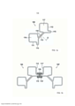
[0021] A Figura 1a mostra uma representação em corte transversal de uma primeira modalidade de um perfil de quadro, que pode chegar à aplicação como perfil de quadro vertical de uma estrutura de quadro para uma unidade de armário de comando elétrico conectável. Nesse caso, o perfil de quadro, que está formado como perfil de câmara oca, apresenta duas câmaras ocas 116,117 opostas uma à outra, que estão conectadas uma à outra por uma peça de união 113. As câmaras ocas 116, 117são substancialmente quadradas e formam entre si, adjacente à peça de união 13, uma ranhura em cauda de andorinha 118, simétrica à diagonal e secção transversal D. Uma das paredes 111 ou 112 de uma câmara oca 116 ou 117 forma, nesse caso, em cada caso, um lado externo da estrutura de quadro. De cada um desses lados de perfil 111, 112 saem prolongamentos de perfil 114, 115, que se estendem, em cada caso, afastados dos lados de perfil 111, 112, mais precisamente sob um ângulo reto aos mesmos. Os prolongamentos de perfil 114, 113 estendem-se sob um ângulo de aproximadamente 135° à peça de união 113.[0021] Figure 1a shows a cross-sectional representation of a first embodiment of a panel profile, which can be applied as a vertical panel profile of a panel structure for a pluggable electrical control cabinet unit. In this case, the frame profile, which is formed as a hollow chamber profile, has two
[0022] A Figura 1b mostra a situação de conexão de dois perfis de quadro 100, 100’ da Figura 1a. O perfil de quadro 100’ está girado por 90° em relação ao perfil de quadro 100, de modo que eles estão opostos em uma disposição especularmente simétrica, sendo que ao prolongamento de perfil 115 do perfil de quadro 100 está oposto o prolongamento de perfil 114’ do perfil de quadro 118. Sobre os prolongamentos de perfil 115, 114’ está colocada uma vedação de inserção 130, que está em forma de H em secção transversal. Nesse caso, o comprimento das seções da vedação 130 em forma de H corresponde, na direção de secção transversal dos perfis de quadro 100, 100’, substancialmente, ao comprimento dos prolongamentos de perfil 115, 114’.[0022] Figure 1b shows the connection situation of two
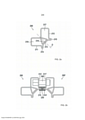
[0023] A Figura 2a mostra uma vista em corte transversal de um perfil de quadro 200, que pode ser entendido como variante do perfil de acordo com a Figura 1a. Novamente, trata-se de um perfil de câmara oca, com duas câmaras ocas 216, 217, que estão conectadas entre si através de uma peça de união 213. As câmaras ocas 216, 217 são substancialmente retangulares e chocam-se, em relação à peça de união 213, com suas bordas uma na outra, de modo que é formada uma terceira câmara oca 218. Duas das paredes 211 ou 212 das câmaras ocas 216, 217 formam, por sua vez, os lados externos da estrutura de quadro, sendo que eles se estendem afastados desses prolongamentos de perfil 214, 215, sob um ângulo reto, para os lados de perfil 211, 212, e, sob um ângulo de 135°, para a peça de união 213, sendo que, resulta, no total, uma configuração especularmente simétrica à diagonal de secção transversal D.[0023] Figure 2a shows a cross-sectional view of a
[0024] A Figura 2b mostra a situação de conexão correspondente, na qual o prolongamento de perfil 215 do perfil de quadro 200 está oposto ao prolongamento e perfil 214’, sob formação de um espaço intermediário, sendo que esse espaço intermediário, por sua vez, é transposto ou fechado por uma vedação e inserção 230 com secção transversal em forma de H. Também aqui, o comprimento das seções d vedação 230 em forma de H corresponde, na direção de secção transversal dos perfis de quadro 200, 200’, substancialmente ao comprimento dos prolongamentos de perfil 215, 214’. A estabilidade da disposição é aumentada pela disposição de conexão 240, sendo que na Figura 2b só uma está representada esquematicamente. Disposições de conexão são conhecidas e são formadas, por exemplo, por uma disposição de pino-porca.[0024] Figure 2b shows the corresponding connection situation, in which the
[0025] A Figura 3 a mostra uma vista em corte transversal de uma terceira modalidade de um perfil de quadro de acordo com os princípios da presente invenção. O perfil de quadro 300 também é um perfil oco, no entanto, com apenas uma câmara oca 316. Os lados d perfil 311, 312, que formam os lados externos da estrutura de quadro, compreendem dois segmentos de lado de perfil 311a, 311b ou 312a, 312b, que passam um para dentro do outro, e que estão angulados de tal modo que o primeiro segmento de lado de perfil 311 a do primeiro lado de perfil 311 estende-se perpendicularmente ao primeiro segmento de lado de perfil 312 a do segundo lado de perfil 312 e o segundo segmento de lado de perfil 311b do primeiro lado de perfil 311 estende-se paralelamente ao segundo segmento de perfil 312b do segundo lado de perfil 312. Nos lados de perfil 311, 312 estão novamente formados prolongamentos d eperfi8l 314, 315, que se estendem afastados dos lados de perfil 311, 312 e estão conectados um ao outro através de um segmento de conexão 313. Sob essa peça de união 311, eles estendem-se sob um ângulo de aproximadamente 135°, assim como aos respectivos segundos segmentos de perfil 311b ou 312b dos lados de perfil 311, 312. O perfil de quadro 300 está novamente simétrico à diagonal de secção transversal D. A secção transversal da câmara oca 316 corresponde, portanto aos dois quadrados, parcialmente colocados um sobre o outro, sendo que o comprimento da peça de união 313 definem o comprimento de lado do quadrado menor, que em relação ao quadrado com um comprimento de lado maior, está situado girado em 45°.[0025] Figure 3 a shows a cross-sectional view of a third embodiment of a frame profile in accordance with the principles of the present invention. The
[0026] A Figura 3b mostra a situação de anexação correspondente de dois perfis de quadro 300, 300’, sendo que os prolongamentos de perfil 315 e 314’ estão opostos um ao outro, sob formação de um espaço intermediário, que está transposto ou fechado por uma vedação de inserção. A vedação de inserção 330 está novamente em forma de H em secção transversal, sendo que as seções opostas do perfil em H, que fecham os prolongamentos de perfil 315 e 314’ estão, no entanto, configurados de modo diferente. Assim, particularmente o lado da vedação 330 voltado para o interior do armário está formado de modo mais forte do que o lado voltado para o exterior, além disso, está dotado de cantos arredondados. Em direção ao exterior está prevista entre os perfis de quadro 300, 300’ uma disposição de conexão 340, aqui na forma de um perfil ou de uma tira de perfil com secção transversal em forma de C.[0026] Figure 3b shows the situation of corresponding attachment of two
[0027] A Figura 4 a mostra uma vista em corte transversal de uma vedação de inserção 510, na qual a secção transversal está substancialmente em forma de H. Duas seções 512, 514 opostas uma à outra formam entre si uma fenda 516 com uma secção transversal aproximadamente retangular, que está dimensionado para uma recepção de ajuste quase preciso de um prolongamento de perfil de um perfil de quadro. As seções 512, 514 estão conectadas uma à outra por uma peça de união 518, que também representa a limitação de profundidade para a fenda 516. Ao primeiro par de seções 512, 514 está oposto um segundo par de seções 520, 522, que também e são conectados um ao outo pela peça de união518 e formam uma fenda 524 entre os mesmos. Diferentemente de uma fenda 516, a secção transversal da fenda 524 não é retangular, mas alarga-se, partindo da peça de união 518, em direção ao exterior, de modo que é formada uma ranhura de recepção, que se estreita para o perfil de quadro a ser conectado ou para o prolongamento de perfil do mesmo. Como a dimensão da fenda 524 na peça de união 518 ou na proximidade da mesma sempre ainda está adaptada à espessura do prolongamento de perfil da estrutura de quadro a se conectada, também aqui está assegurado um ajuste hermético para poeira e umidade.[0027] Figure 4 a shows a cross-sectional view of an
[0028] A Figura 4b mostra uma outra modalidade de uma vedação de inserção 530, na qual entre duas seções 532 e 534 opostas uma à outra está formada uma fenda 536, cuja largura pode ser menor do que a espessura do prolongamento de perfil, sobre o qual a vedação de inserção 530 deve ser inserida. Por seleção de material apropriada é obtido que as seções 532, 534 fechem hermeticamente o prolongamento de perfil, sob aproveitamento da tensão própria do material. A peça de união, que conecta as seções 532, 534 estende-se de um rebordo 540, sob formação de uma superfície de encosto 531, para um rebordo 542. A superfície de encosto tem uma largura, que é maior do que a largura da vedação e inserção 530 na região das seções 532, 534 opostas uma à outra. Por essa media, pro um lado, é assegurado que tolerâncias na colocação lado a lado de perfis de quadro a ser conectados podem ser compensadas, por outro lado, uma configuração desse tipo de uma vedação e inserção 530 abre a possibilidade de ser conectado um perfil de outro tipo. Por exemplo, entre as seções 532, 534 pode ser inserido o prolongamento de perfil de um perfil de acordo com a Figura 3a, enquanto na superfície de encosto 538 pode ser conectado, por exemplo, o prolongamento de perfil de um perfil de quadro de acordo com a Figura 1a. A possiblidade de conexão não está limitada às configurações de perfis de quadro representados nesse pedido.[0028] Figure 4b shows another embodiment of an
[0029] A Figura 4c mostra uma vista em corte transversal de uma outra vedação de inserção 550, que representa uma variante da vedação de inserção 530 de acordo com a Figura 4b. Nesse caos, nas seções 552, 554 opostas uma à outra, uma, a saber 554, está encurtada, mas, não obstante, apresenta um comprimento que assegura a formação de uma fenda 556 entre as seções 552, 554. Novamente está prevista a superfície de encosto 558 ampliada, que se estende entre os rebordos 560, 562 da peça de união, que conecta as seções 552, 554. Em relação à modalidade de acordo com a Figura 4b, resulta o aperfeiçoamento adicional que a inserção da vedação de inserção 550 sobre um prolongamento de perfil de um perfil de quadro é facilitada pela configuração diferente das seções 552, 554, uma vez que não é preciso realizar uma inserção, mas a aplicação é obtida por um movimento de tombamento da vedação de inserção 550.[0029] Figure 4c shows a cross-sectional view of another
[0030] Com a invenção está à disposição, no total, um sistema de armário de comando elétrico, no qual a instalação da vedação entre duas unidades de armário de comando elétrico conectáveis pode ser realizada sem ferramentas.[0030] In total, an electrical control cabinet system is available with the invention, in which the installation of the seal between two connectable electrical control cabinet units can be carried out without tools.
[0031] As características da invenção descrias na descrição acima, nos desenhos, bem como nas reivindicações podem ser essenciais pra a concretização da invenção, tanto individualmente como também em qualquer combinação.[0031] The features of the invention described in the above description, in the drawings, as well as in the claims can be essential for the embodiment of the invention, either individually or in any combination.
Claims (9)
Applications Claiming Priority (3)
| Application Number | Priority Date | Filing Date | Title |
|---|---|---|---|
| DE102014101401.4A DE102014101401A1 (en) | 2014-02-05 | 2014-02-05 | Baying cabinet system |
| DE102014101401.4 | 2014-02-05 | ||
| PCT/DE2015/100036 WO2015117599A1 (en) | 2014-02-05 | 2015-01-28 | Lined-up electrical enclosure system |
Publications (2)
| Publication Number | Publication Date |
|---|---|
| BR112016017516A2 BR112016017516A2 (en) | 2017-08-08 |
| BR112016017516B1 true BR112016017516B1 (en) | 2022-02-01 |
Family
ID=52574001
Family Applications (1)
| Application Number | Title | Priority Date | Filing Date |
|---|---|---|---|
| BR112016017516-6A BR112016017516B1 (en) | 2014-02-05 | 2015-01-28 | CONNECTED ELECTRICAL CONTROL CABINET SYSTEM |
Country Status (16)
| Country | Link |
|---|---|
| US (1) | US9991684B2 (en) |
| EP (1) | EP3103172B1 (en) |
| JP (1) | JP6306194B2 (en) |
| KR (1) | KR102217479B1 (en) |
| CN (1) | CN106063060B (en) |
| BR (1) | BR112016017516B1 (en) |
| CA (1) | CA2937572C (en) |
| DE (1) | DE102014101401A1 (en) |
| ES (1) | ES2742449T3 (en) |
| HU (1) | HUE045529T2 (en) |
| MX (1) | MX2016009258A (en) |
| PL (1) | PL3103172T3 (en) |
| RU (1) | RU2665472C1 (en) |
| TR (1) | TR201909580T4 (en) |
| UA (1) | UA119255C2 (en) |
| WO (1) | WO2015117599A1 (en) |
Families Citing this family (15)
| Publication number | Priority date | Publication date | Assignee | Title |
|---|---|---|---|---|
| DE102014101402A1 (en) | 2014-02-05 | 2015-08-20 | Rittal Gmbh & Co. Kg | Frame profile for a frame of a control cabinet |
| DE102015121193B4 (en) * | 2015-12-04 | 2017-07-13 | Rittal Gmbh & Co. Kg | Framework for a control cabinet arrangement |
| DE102015121192B4 (en) * | 2015-12-04 | 2019-09-19 | Rittal Gmbh & Co. Kg | Frame for a control cabinet |
| ES2891538T3 (en) | 2016-06-27 | 2022-01-28 | Rittal Gmbh & Co Kg | A flat part bracket for attaching a flat part to the frame of an electrical cabinet and the corresponding electrical cabinet |
| DE102016117378B3 (en) | 2016-09-15 | 2017-05-18 | Rittal Gmbh & Co. Kg | Hinge arrangement for a control cabinet |
| DE102016123230B3 (en) | 2016-12-01 | 2017-11-16 | Rittal Gmbh & Co. Kg | Hinge arrangement for a control cabinet housing and a corresponding control cabinet housing |
| DE102016124078B3 (en) * | 2016-12-12 | 2018-05-09 | Rittal Gmbh & Co. Kg | Connecting arrangement for the connection of two control cabinet frame racks |
| DE102016015791B4 (en) * | 2016-12-12 | 2019-01-03 | Rittal Gmbh & Co. Kg | Connecting arrangement for the connection of two control cabinet frame racks |
| DE102017108335B4 (en) | 2017-04-19 | 2019-01-03 | Rittal Gmbh & Co. Kg | Mounting arrangement and a corresponding cabinet housing |
| DE102017114385B4 (en) | 2017-06-28 | 2021-06-24 | Rittal Gmbh & Co. Kg | Control cabinet frame with locked base frame |
| DE102017127576A1 (en) | 2017-11-22 | 2019-05-23 | Rittal Gmbh & Co. Kg | Closing device for a control cabinet and a corresponding control cabinet |
| DE202018100613U1 (en) | 2018-02-05 | 2018-02-14 | Rittal Gmbh & Co. Kg | Arrangement with two interconnected via a bay connector control cabinet frame racks |
| DE102018109601B4 (en) | 2018-04-20 | 2024-05-23 | Rittal Gmbh & Co. Kg | Control cabinet arrangement with protective conductor function |
| JP7077147B2 (en) * | 2018-05-31 | 2022-05-30 | 株式会社東芝 | Electronics |
| CN114614176A (en) * | 2022-03-25 | 2022-06-10 | 中创新航科技股份有限公司 | Energy storage rack |
Family Cites Families (36)
| Publication number | Priority date | Publication date | Assignee | Title |
|---|---|---|---|---|
| DE2207068A1 (en) * | 1971-02-17 | 1972-08-31 | Moldow, Preben Georg, Birkeroed (Danemark) | Connection device for tubular channel elements |
| US5106173A (en) * | 1988-06-10 | 1992-04-21 | Herman Miller, Inc. | Work space management system and cabinet therefor |
| FR2648005B1 (en) * | 1989-06-05 | 1993-11-26 | Merlin Gerin | WATERPROOF CABINET OF ELECTRICAL EQUIPMENT |
| DE4336204C2 (en) * | 1993-10-23 | 1996-11-07 | Loh Kg Rittal Werk | Frame for a control cabinet |
| DE4336187C2 (en) * | 1993-10-23 | 1996-12-12 | Loh Kg Rittal Werk | Frame leg for a frame of a control cabinet |
| DE4439614C1 (en) * | 1994-11-05 | 1995-12-14 | Loh Kg Rittal Werk | Frame structure for electrical switching cabinet |
| DE29521934U1 (en) * | 1995-10-04 | 1998-09-24 | Loh Kg Rittal Werk | Frame leg for a control cabinet |
| DE19536950C1 (en) * | 1995-10-04 | 1996-11-21 | Loh Kg Rittal Werk | Shaped frame struts for construction of switch-cabinet housing |
| US6120206A (en) * | 1996-05-30 | 2000-09-19 | Rittal-Werk Loh Gmbh & Co. Kg | Switch cabinet with rack and wall elements |
| DE29623065U1 (en) * | 1996-11-19 | 1997-10-02 | Loh Kg Rittal Werk | Frame profile for a frame of a control cabinet |
| DE29623551U1 (en) * | 1996-11-19 | 1998-10-01 | Loh Kg Rittal Werk | switch cabinet |
| FR2756111B1 (en) | 1996-11-21 | 1998-12-24 | Schneider Electric Sa | ENCLOSURE ASSEMBLY FOR HOUSING ELECTRICAL APPARATUS |
| US5997117A (en) * | 1997-06-06 | 1999-12-07 | Chatsworth Products, Inc. | Rack frame cabinet |
| DE19750427C1 (en) * | 1997-11-14 | 1999-07-08 | Loh Kg Rittal Werk | Fastening device |
| DE19817919A1 (en) * | 1998-04-17 | 1999-10-21 | Loh Kg Rittal Werk | Frame leg for a frame of a control cabinet |
| DE19817916A1 (en) * | 1998-04-17 | 1999-10-21 | Loh Kg Rittal Werk | Frame leg for a frame of a control cabinet |
| DE19818603A1 (en) * | 1998-04-20 | 1999-10-21 | Loh Kg Rittal Werk | Frame leg for a frame of a control cabinet |
| DE19853611C1 (en) * | 1998-11-20 | 2000-04-06 | Skeppner Hans | Electrical equipment cabinet has attachment strip with a row of holes between sealing edges or surfaces, enabling covering elements to be attached without penetrating wall of frame profile |
| IT249686Y1 (en) * | 2000-01-05 | 2003-05-28 | Cost El S P A | PROFILE FOR FRAMES OF WINDOW CABINETS OR SIMILAR |
| US20010050516A1 (en) * | 2000-03-09 | 2001-12-13 | Nitto Electric Works, Ltd | Frame construction of a cabinet or cabinets for containing electronic and electric equipments |
| JP2002319778A (en) * | 2001-04-20 | 2002-10-31 | Nitto Electric Works Ltd | Frame of cabinet for accommodating electric/electronic apparatus |
| DE10207364B4 (en) * | 2001-03-01 | 2007-06-14 | Nitto Electric Works, Ltd. | Frame member for housings of electrical and electronic equipment and rack link connecting construction |
| JP2002280770A (en) * | 2001-03-19 | 2002-09-27 | Nitto Electric Works Ltd | Vertical frame of cabinet for housing electric/electronic apparatus |
| DE10113936C1 (en) * | 2001-03-21 | 2002-10-10 | Rittal Rcs Comm Systems Gmbh & Co Kg | Electrical cabinet with frame chassis and cladding elements has at least inside surfaces of angled edges of vertical cladding elements at 45 degrees to inside surfaces of cladding elements |
| DE10113924C1 (en) * | 2001-03-21 | 2002-07-18 | Rittal Rcs Comm Systems Gmbh & Co Kg | Mounting for fixing to switch cabinet frame has fixing plate with central fixing bore and complementary coupling projections and coupling recesses perpendicular to bore axis |
| US6945616B2 (en) * | 2001-04-02 | 2005-09-20 | Emerson Network Power, Energy Systems, North America, Inc. | Modular enclosure system for electronic equipment |
| ITMI20020473A1 (en) * | 2002-03-06 | 2003-09-08 | Abb Service Srl | UPRIGHT STRUCTURE FOR ELECTRICAL DISTRIBUTION CABINETS |
| BR0301083A (en) | 2003-04-03 | 2004-11-03 | Melquisedec Francisquini | Improvement in metallic profile for composition of structures for mounting electrical panels |
| FR2870995B1 (en) * | 2004-05-28 | 2006-09-01 | Hispano Mecano Electrica Sa Sa | ELECTRICAL CABINET WITH OSSATURE PROFILES |
| CN101418905A (en) * | 2007-10-26 | 2009-04-29 | 申随章 | Fifteen-folding profile material |
| RU2384285C2 (en) * | 2008-05-12 | 2010-03-20 | Андрей Витальевич Машкин | Frame structure of distribution cabinet |
| US8128183B2 (en) * | 2009-07-17 | 2012-03-06 | Sanmina Sci-Corporation | Rack system |
| CN201690116U (en) * | 2010-06-10 | 2010-12-29 | 无锡豪润金属制品有限公司 | Profile for upright post of cabinet body |
| DE102010033319A1 (en) * | 2010-08-04 | 2012-02-09 | Protektorwerk Florenz Maisch Gmbh & Co. Kg | Cabinet profile, in particular control cabinet profile and cabinet, in particular control cabinet |
| KR101438594B1 (en) * | 2012-12-28 | 2014-09-12 | 주식회사 케이디파워 | Assembly Switch board |
| RU133357U1 (en) * | 2013-04-23 | 2013-10-10 | Общество с ограниченной ответственностью Научно-производственное предприятие "ЭКРА" | FRAME DISTRIBUTION CABINET |
-
2014
- 2014-02-05 DE DE102014101401.4A patent/DE102014101401A1/en not_active Withdrawn
-
2015
- 2015-01-28 CA CA2937572A patent/CA2937572C/en active Active
- 2015-01-28 EP EP15705902.3A patent/EP3103172B1/en active Active
- 2015-01-28 BR BR112016017516-6A patent/BR112016017516B1/en active IP Right Grant
- 2015-01-28 WO PCT/DE2015/100036 patent/WO2015117599A1/en active Application Filing
- 2015-01-28 JP JP2016546507A patent/JP6306194B2/en active Active
- 2015-01-28 CN CN201580007456.3A patent/CN106063060B/en active Active
- 2015-01-28 PL PL15705902T patent/PL3103172T3/en unknown
- 2015-01-28 UA UAA201609153A patent/UA119255C2/en unknown
- 2015-01-28 HU HUE15705902A patent/HUE045529T2/en unknown
- 2015-01-28 RU RU2016135688A patent/RU2665472C1/en active
- 2015-01-28 ES ES15705902T patent/ES2742449T3/en active Active
- 2015-01-28 KR KR1020167021585A patent/KR102217479B1/en active IP Right Grant
- 2015-01-28 TR TR2019/09580T patent/TR201909580T4/en unknown
- 2015-01-28 MX MX2016009258A patent/MX2016009258A/en active IP Right Grant
- 2015-01-28 US US15/116,735 patent/US9991684B2/en active Active
Also Published As
| Publication number | Publication date |
|---|---|
| US9991684B2 (en) | 2018-06-05 |
| HUE045529T2 (en) | 2020-01-28 |
| US20160352083A1 (en) | 2016-12-01 |
| KR102217479B1 (en) | 2021-02-22 |
| MX2016009258A (en) | 2017-05-01 |
| WO2015117599A1 (en) | 2015-08-13 |
| EP3103172B1 (en) | 2019-05-22 |
| RU2665472C1 (en) | 2018-08-30 |
| TR201909580T4 (en) | 2019-07-22 |
| PL3103172T3 (en) | 2019-09-30 |
| ES2742449T3 (en) | 2020-02-14 |
| UA119255C2 (en) | 2019-05-27 |
| CN106063060B (en) | 2020-03-10 |
| JP6306194B2 (en) | 2018-04-04 |
| BR112016017516A2 (en) | 2017-08-08 |
| JP2017507633A (en) | 2017-03-16 |
| CA2937572A1 (en) | 2015-08-13 |
| CN106063060A (en) | 2016-10-26 |
| KR20160117474A (en) | 2016-10-10 |
| CA2937572C (en) | 2019-08-13 |
| EP3103172A1 (en) | 2016-12-14 |
| DE102014101401A1 (en) | 2015-08-06 |
Similar Documents
| Publication | Publication Date | Title |
|---|---|---|
| BR112016017516B1 (en) | CONNECTED ELECTRICAL CONTROL CABINET SYSTEM | |
| BR112016017303B1 (en) | FRAME PROFILE OF A FRAME STRUCTURE FOR AN ELECTRICAL OR DISTRIBUTION CABINET AND MOUNTING BOARD FOR USE WITH AT LEAST THE FRAME PROFILE | |
| US20200199869A1 (en) | Process for producing a recess in the base region of a wall construction, corresponding wall construction and system and construction element therefor | |
| ES2688979T3 (en) | Sectional gate | |
| BR112012030824B1 (en) | QUICK DOOR | |
| BR112015029563A8 (en) | AIR-AIR HEAT EXCHANGER | |
| ES2242083T3 (en) | WALL DEVICE FOR MOUNTING ACCESSORIES. | |
| EP4248048A1 (en) | Profile assembly and method for assembling this type of profile assembly | |
| BRPI0710910B8 (en) | clamping device | |
| BR112018069824A2 (en) | stator frame of an electric machine and an electric machine | |
| JP6513481B2 (en) | Telescopic guide rail | |
| ES2837527T3 (en) | Set with two switch cabinet frames connected to each other via a junction connector | |
| CN207553388U (en) | A kind of hyperboloid curtain wall with two level waterproof construction | |
| DK2846429T3 (en) | Electrical installation housing | |
| ES2553651T3 (en) | Gasket fixing arrangement | |
| ITMI20012549A1 (en) | CABLE HOUSING DEVICE | |
| BR112018074033A2 (en) | partition and assembly and construction method for such partition | |
| ES1077426U (en) | Clamp profile for dividing wall panels (Machine-translation by Google Translate, not legally binding) | |
| JP6335817B2 (en) | Panel body | |
| JP6097033B2 (en) | Stud for partition wall and construction method of partition wall | |
| ITAN20120044A1 (en) | MOUNTING KIT FOR A COUNTERFRAME FOR WINDOWS | |
| BR112017003033A2 (en) | edge profile element for a ceiling substructure, ceiling substructure, ceiling construction, method for fabricating a ceiling substructure, and employing an edge profile element | |
| BR102013004911B1 (en) | security switch cabinet | |
| IT201900013074A1 (en) | Profile for ducts of ventilation systems | |
| ITUD20090084A1 (en) | SUPPORT CHASSIS AND ITS ASSEMBLY PROCEDURE |
Legal Events
| Date | Code | Title | Description |
|---|---|---|---|
| B06U | Preliminary requirement: requests with searches performed by other patent offices: procedure suspended [chapter 6.21 patent gazette] | ||
| B09A | Decision: intention to grant [chapter 9.1 patent gazette] | ||
| B16A | Patent or certificate of addition of invention granted [chapter 16.1 patent gazette] |
Free format text: PRAZO DE VALIDADE: 20 (VINTE) ANOS CONTADOS A PARTIR DE 28/01/2015, OBSERVADAS AS CONDICOES LEGAIS. |