BR112016012873B1 - FUEL SYSTEM FOR PRESSURIZED FUEL DELIVERY FOR BOTH AN INTERNAL COMBUSTION ENGINE AND AN EXHAUST INSTALLATION, AND INTERNAL COMBUSTION ENGINE ARRANGEMENT - Google Patents
FUEL SYSTEM FOR PRESSURIZED FUEL DELIVERY FOR BOTH AN INTERNAL COMBUSTION ENGINE AND AN EXHAUST INSTALLATION, AND INTERNAL COMBUSTION ENGINE ARRANGEMENT Download PDFInfo
- Publication number
- BR112016012873B1 BR112016012873B1 BR112016012873-7A BR112016012873A BR112016012873B1 BR 112016012873 B1 BR112016012873 B1 BR 112016012873B1 BR 112016012873 A BR112016012873 A BR 112016012873A BR 112016012873 B1 BR112016012873 B1 BR 112016012873B1
- Authority
- BR
- Brazil
- Prior art keywords
- fuel
- exhaust
- supply circuit
- pressure
- fuel supply
- Prior art date
Links
Images
Classifications
-
- F—MECHANICAL ENGINEERING; LIGHTING; HEATING; WEAPONS; BLASTING
- F02—COMBUSTION ENGINES; HOT-GAS OR COMBUSTION-PRODUCT ENGINE PLANTS
- F02D—CONTROLLING COMBUSTION ENGINES
- F02D41/00—Electrical control of supply of combustible mixture or its constituents
- F02D41/30—Controlling fuel injection
- F02D41/3082—Control of electrical fuel pumps
-
- F—MECHANICAL ENGINEERING; LIGHTING; HEATING; WEAPONS; BLASTING
- F01—MACHINES OR ENGINES IN GENERAL; ENGINE PLANTS IN GENERAL; STEAM ENGINES
- F01N—GAS-FLOW SILENCERS OR EXHAUST APPARATUS FOR MACHINES OR ENGINES IN GENERAL; GAS-FLOW SILENCERS OR EXHAUST APPARATUS FOR INTERNAL COMBUSTION ENGINES
- F01N3/00—Exhaust or silencing apparatus having means for purifying, rendering innocuous, or otherwise treating exhaust
- F01N3/02—Exhaust or silencing apparatus having means for purifying, rendering innocuous, or otherwise treating exhaust for cooling, or for removing solid constituents of, exhaust
- F01N3/021—Exhaust or silencing apparatus having means for purifying, rendering innocuous, or otherwise treating exhaust for cooling, or for removing solid constituents of, exhaust by means of filters
- F01N3/023—Exhaust or silencing apparatus having means for purifying, rendering innocuous, or otherwise treating exhaust for cooling, or for removing solid constituents of, exhaust by means of filters using means for regenerating the filters, e.g. by burning trapped particles
- F01N3/025—Exhaust or silencing apparatus having means for purifying, rendering innocuous, or otherwise treating exhaust for cooling, or for removing solid constituents of, exhaust by means of filters using means for regenerating the filters, e.g. by burning trapped particles using fuel burner or by adding fuel to exhaust
- F01N3/0253—Exhaust or silencing apparatus having means for purifying, rendering innocuous, or otherwise treating exhaust for cooling, or for removing solid constituents of, exhaust by means of filters using means for regenerating the filters, e.g. by burning trapped particles using fuel burner or by adding fuel to exhaust adding fuel to exhaust gases
-
- F—MECHANICAL ENGINEERING; LIGHTING; HEATING; WEAPONS; BLASTING
- F01—MACHINES OR ENGINES IN GENERAL; ENGINE PLANTS IN GENERAL; STEAM ENGINES
- F01N—GAS-FLOW SILENCERS OR EXHAUST APPARATUS FOR MACHINES OR ENGINES IN GENERAL; GAS-FLOW SILENCERS OR EXHAUST APPARATUS FOR INTERNAL COMBUSTION ENGINES
- F01N3/00—Exhaust or silencing apparatus having means for purifying, rendering innocuous, or otherwise treating exhaust
- F01N3/08—Exhaust or silencing apparatus having means for purifying, rendering innocuous, or otherwise treating exhaust for rendering innocuous
- F01N3/10—Exhaust or silencing apparatus having means for purifying, rendering innocuous, or otherwise treating exhaust for rendering innocuous by thermal or catalytic conversion of noxious components of exhaust
- F01N3/24—Exhaust or silencing apparatus having means for purifying, rendering innocuous, or otherwise treating exhaust for rendering innocuous by thermal or catalytic conversion of noxious components of exhaust characterised by constructional aspects of converting apparatus
- F01N3/36—Arrangements for supply of additional fuel
-
- F—MECHANICAL ENGINEERING; LIGHTING; HEATING; WEAPONS; BLASTING
- F02—COMBUSTION ENGINES; HOT-GAS OR COMBUSTION-PRODUCT ENGINE PLANTS
- F02D—CONTROLLING COMBUSTION ENGINES
- F02D41/00—Electrical control of supply of combustible mixture or its constituents
- F02D41/30—Controlling fuel injection
- F02D41/38—Controlling fuel injection of the high pressure type
-
- F—MECHANICAL ENGINEERING; LIGHTING; HEATING; WEAPONS; BLASTING
- F02—COMBUSTION ENGINES; HOT-GAS OR COMBUSTION-PRODUCT ENGINE PLANTS
- F02M—SUPPLYING COMBUSTION ENGINES IN GENERAL WITH COMBUSTIBLE MIXTURES OR CONSTITUENTS THEREOF
- F02M55/00—Fuel-injection apparatus characterised by their fuel conduits or their venting means; Arrangements of conduits between fuel tank and pump F02M37/00
-
- F—MECHANICAL ENGINEERING; LIGHTING; HEATING; WEAPONS; BLASTING
- F01—MACHINES OR ENGINES IN GENERAL; ENGINE PLANTS IN GENERAL; STEAM ENGINES
- F01N—GAS-FLOW SILENCERS OR EXHAUST APPARATUS FOR MACHINES OR ENGINES IN GENERAL; GAS-FLOW SILENCERS OR EXHAUST APPARATUS FOR INTERNAL COMBUSTION ENGINES
- F01N2610/00—Adding substances to exhaust gases
- F01N2610/03—Adding substances to exhaust gases the substance being hydrocarbons, e.g. engine fuel
-
- F—MECHANICAL ENGINEERING; LIGHTING; HEATING; WEAPONS; BLASTING
- F01—MACHINES OR ENGINES IN GENERAL; ENGINE PLANTS IN GENERAL; STEAM ENGINES
- F01N—GAS-FLOW SILENCERS OR EXHAUST APPARATUS FOR MACHINES OR ENGINES IN GENERAL; GAS-FLOW SILENCERS OR EXHAUST APPARATUS FOR INTERNAL COMBUSTION ENGINES
- F01N2610/00—Adding substances to exhaust gases
- F01N2610/14—Arrangements for the supply of substances, e.g. conduits
- F01N2610/1433—Pumps
- F01N2610/144—Control thereof
-
- F—MECHANICAL ENGINEERING; LIGHTING; HEATING; WEAPONS; BLASTING
- F01—MACHINES OR ENGINES IN GENERAL; ENGINE PLANTS IN GENERAL; STEAM ENGINES
- F01N—GAS-FLOW SILENCERS OR EXHAUST APPARATUS FOR MACHINES OR ENGINES IN GENERAL; GAS-FLOW SILENCERS OR EXHAUST APPARATUS FOR INTERNAL COMBUSTION ENGINES
- F01N2610/00—Adding substances to exhaust gases
- F01N2610/14—Arrangements for the supply of substances, e.g. conduits
- F01N2610/1493—Purging the reducing agent out of the conduits or nozzle
-
- F—MECHANICAL ENGINEERING; LIGHTING; HEATING; WEAPONS; BLASTING
- F02—COMBUSTION ENGINES; HOT-GAS OR COMBUSTION-PRODUCT ENGINE PLANTS
- F02D—CONTROLLING COMBUSTION ENGINES
- F02D2200/00—Input parameters for engine control
- F02D2200/02—Input parameters for engine control the parameters being related to the engine
- F02D2200/06—Fuel or fuel supply system parameters
- F02D2200/0602—Fuel pressure
Abstract
um sistema de combustível para uma disposição de motor de combustão interna a presente invenção se refere a um sistema de combustível para entrega de combustível pressurizado tanto para um motor de combustão interna e quanto para uma instalação de exaustão, o sistema de combustível compreendendo duas ramificações separadas para entrega de combustível para o motor de combustão interna e para a ramificação de exaustão, e compreendendo uma bomba de combustível primária entregando combustível para ambas as ramificações do circuito de combustível. em concordância com a presente invenção, o sistema de combustível é caracterizado pelo fato de que a saída de bomba de combustível primária é controlável independentemente da velocidade de motor. a saída da bomba de combustível primária (30) pode ser controlada de maneira tal que a pressão no circuito de suprimento de combustível depende de se combustível é para ser entregue para a instalação de exaustão. o sistema de combustível pode compreender uma disposição de válvula de fechamento (desligamento) hidraulicamente controlada (52, 68, 82) que é forçada para permutar entre um estado fechado e um estado aberto dependendo da pressão no circuito de suprimento de combustível (40, 44).A fuel system for an internal combustion engine arrangement The present invention relates to a fuel system for delivering pressurized fuel to both an internal combustion engine and an exhaust facility, the fuel system comprising two separate branches for delivering fuel to the internal combustion engine and to the exhaust branch, and comprising a primary fuel pump delivering fuel to both branches of the fuel circuit. In accordance with the present invention, the fuel system is characterized in that the primary fuel pump output is controllable independently of engine speed. the output of the primary fuel pump (30) can be controlled in such a way that the pressure in the fuel supply circuit depends on whether fuel is to be delivered to the exhaust installation. the fuel system may comprise a hydraulically controlled shut-off valve arrangement (52, 68, 82) which is forced to switch between a closed state and an open state depending on pressure in the fuel supply circuit (40, 44). ).
Description
[001] A presente invenção se refere a um sistema de combustível para entrega de combustível pressurizado tanto para um motor de combustão interna e quanto para um sistema de pós-tratamento de exaustão.[001] The present invention relates to a fuel system for delivering pressurized fuel both for an internal combustion engine and for an exhaust aftertreatment system.
[002] A presente invenção pode ser aplicada em sistemas de combustível para serem utilizados com disposições de motor de combustão interna que podem ser instalados em veículos comerciais pesados, tais como caminhões, ônibus e equipamento de construção. Embora a presente invenção venha a ser descrita com respeito para um caminhão, a presente invenção não é restrita para esta aplicação particular, mas pode também ser utilizada em outros veículos ou máquinas, ou em disposições de combustão interna fixas tracionando bombas, geradores, ou outro maquinário.[002] The present invention can be applied in fuel systems to be used with internal combustion engine arrangements that can be installed in heavy commercial vehicles such as trucks, buses and construction equipment. Although the present invention will be described with respect to a truck, the present invention is not restricted to this particular application, but may also be used in other vehicles or machines, or in fixed internal combustion arrangements pulling pumps, generators, or the like. machinery.
[003] É agora comum para disposições de motor de combustão interna ser equipadas com sistemas de pós- tratamento de exaustão para reduzir a quantidade de substâncias nocivas presentes nos gases de exaustão produzidos pela combustão de combustível no motor de combustão interna. Tais sistemas de pós-tratamento de exaustão podem ser integrados em uma instalação de exaustão que coleta os gases de exaustão produzidos pela combustão de combustível no motor de combustão interna, e que rejeita os gases de exaustão, por exemplo, para a atmosfera. Um sistema de pós-tratamento de exaustão pode compreender, inter alia, um ou diversos de um dispositivo de catalisador de oxidação, tal como um dispositivo de catalisador de oxidação de diesel, de um filtro de particulado, tal como um filtro de particulado de diesel ou DPF (Diesel Particulate Filter), ou de um dispositivo de catalisador de redução, tal como um dispositivo de catalisador de redução de NOx [tipicamente um dispositivo de catalisador de redução catalítica seletiva conhecido como dispositivo de SCR (Selective Catalyst Reduction)].[003] It is now common for internal combustion engine arrangements to be equipped with exhaust aftertreatment systems to reduce the amount of harmful substances present in the exhaust gases produced by the combustion of fuel in the internal combustion engine. Such exhaust aftertreatment systems can be integrated into an exhaust installation that collects the exhaust gases produced by the combustion of fuel in the internal combustion engine, and which rejects the exhaust gases, for example, into the atmosphere. An exhaust aftertreatment system may comprise, inter alia, one or more of an oxidation catalyst device, such as a diesel oxidation catalyst device, a particulate filter, such as a diesel particulate filter or DPF (Diesel Particulate Filter), or from a catalyst reduction device such as a NOx reduction catalyst device [typically a selective catalytic reduction catalyst device known as a SCR (Selective Catalyst Reduction) device].
[004] Para a operação de tais dispositivos de pós-tratamento de exaustão, é em alguns casos necessário proporcionar a instalação de exaustão com combustível. Combustível pode, por exemplo, ser utilizado para produzir calor, por ser queimado ou oxidado, ou como um reagente em uma reação química em um conversor de catalisador. Tipicamente, combustível pode ser injetado na corrente de gás de exaustão à montante de um catalisador de oxidação onde o mesmo pode ser oxidado para produzir calor, por exemplo, para regeneração de um filtro de particulado ou para aquecimento dos gases para alcançar uma temperatura de gás adequada para que os mesmos venham a reagir em um catalisador. Combustível pode ser alimentado para um queimador na instalação de exaustão, também para proporcionar calor para os gases de exaustão e para a instalação. Combustível pode ser injetado à montante de um dispositivo de catalisador para reagir em referido dispositivo de catalisador com algumas das substâncias contidas nos gases de exaustão. Por exemplo, a instalação de exaustão pode compreender um bocal de combustível, que pode fazer parte de um injetor de combustível controlado, para injeção de combustível na instalação de exaustão, por exemplo, em uma tubulação de exaustão ou em uma câmara de misturação da instalação de exaustão.[004] For the operation of such exhaust after-treatment devices, it is in some cases necessary to provide the installation of exhaust with fuel. Fuel can, for example, be used to produce heat, by being burned or oxidized, or as a reactant in a chemical reaction in a catalyst converter. Typically, fuel can be injected into the exhaust gas stream upstream of an oxidation catalyst where it can be oxidized to produce heat, for example, for regeneration of a particulate filter or for heating the gases to reach a gas temperature suitable for them to react in a catalyst. Fuel can be fed to a burner in the exhaust installation, also to provide heat for the exhaust gases and for the installation. Fuel can be injected upstream of a catalyst device to react in said catalyst device with some of the substances contained in the exhaust gases. For example, the exhaust installation may comprise a fuel nozzle, which may be part of a controlled fuel injector, for injecting fuel into the exhaust installation, for example, in an exhaust pipe or in a mixing chamber of the installation. of exhaustion.
[005] Consequentemente, em tais instalações de exaustão, existe uma necessidade para entrega de combustível pressurizado para a instalação de exaustão. Neste sentido, muitas instalações conhecidas compreendem uma bomba de combustível dedicada.[005] Consequently, in such exhaust installations, there is a need for delivery of pressurized fuel to the exhaust installation. In this regard, many known installations comprise a dedicated fuel pump.
[006] O documento de pedido de patente norte americano número US 2008/0245028 descreve um sistema de combustível onde um sistema de suprimento de combustível de motor (20) possuindo uma bomba de combustível de baixa pressão (22) que bombeia combustível a partir de um tanque (21) para um conduíte (23). O conduíte (23) conecta para uma bomba de combustível de alta pressão (24), que supre uma grade comum de alta pressão (25). Injetores de combustível (26) admitem combustível a partir da grade comum (25) para os cilindros de um motor a diesel (não mostrado), que é operativo para produzir a exaustão transportada (realizada) pela linha de exaustão (30). Uma válvula de alívio de alta pressão (27) pode retornar combustível a partir da grade comum (27) para o tanque de combustível (21). A válvula de regulagem de fluxo (11) é configurada para seletivamente admitir combustível a partir do conduíte (23). Como é estabelecido no referido documento, drenagem de combustível para injeção de combustível de linha de exaustão a partir do conduíte (23) apresenta a vantagem de eliminação da necessidade de uma bomba de combustível adicional separada a partir do sistema de suprimento de combustível de motor (20), mas apresenta a desvantagem de que a pressão no conduíte (23) varia significativamente durante operação normal do motor, devido para o fato de que a bomba de combustível de baixa pressão de um sistema de suprimento de combustível de motor é tipicamente mecanicamente tracionada pelo motor em si mesmo e, conseqüentemente, entrega um fluxo de saída que é substancialmente proporcional para a velocidade de motor. O fato de que a pressão entregue para o sistema de exaustão pode variar bastante, pode apresentar um impacto sobre a precisão do controle da quantidade de combustível que é entregue para o sistema de exaustão.[006] US patent application document number US 2008/0245028 describes a fuel system where an engine fuel supply system (20) having a low pressure fuel pump (22) that pumps fuel from a tank (21) to a conduit (23). Conduit (23) connects to a high pressure fuel pump (24), which supplies a common high pressure grid (25). Fuel injectors (26) admit fuel from the common grid (25) to the cylinders of a diesel engine (not shown), which is operative to produce exhaust carried (carried out) by the exhaust line (30). A high pressure relief valve (27) can return fuel from the common grid (27) to the fuel tank (21). The flow regulation valve (11) is configured to selectively admit fuel from the conduit (23). As stated in that document, fuel drain for exhaust line fuel injection from conduit (23) has the advantage of eliminating the need for an additional fuel pump separate from the engine fuel supply system ( 20), but has the disadvantage that conduit pressure (23) varies significantly during normal engine operation, due to the fact that the low pressure fuel pump of an engine fuel supply system is typically mechanically driven. by the engine itself and, consequently, delivers an output flow that is substantially proportional to the engine speed. The fact that the pressure delivered to the exhaust system can vary greatly can have an impact on the accuracy of controlling the amount of fuel that is delivered to the exhaust system.
[007] Um objetivo da presente invenção é o de proporcionar um sistema de combustível simplificado que pode possibilitar um bom controle da quantidade de combustível injetado no sistema de exaustão sem requerimento de componentes dispendiosos ou complexos para o sistema de injeção de combustível de exaustão.[007] An objective of the present invention is to provide a simplified fuel system that can enable a good control of the amount of fuel injected into the exhaust system without requiring expensive or complex components for the exhaust fuel injection system.
[008] O objetivo da presente invenção é conseguido por um sistema de combustível em concordância com a reivindicação de patente independente 1 acompanhante.[008] The object of the present invention is achieved by a fuel system in accordance with the accompanying independent patent claim 1.
[009] Pela provisão de um sistema de combustível onde a saída de bomba de combustível primária é controlável independentemente da velocidade de motor, a vantagem é determinada em que, no contexto de uma bomba primária comum para ambas as ramificações do circuito de suprimento de combustível, é possível ajustar a saída de bomba primária dependendo das necessidades da instalação de exaustão, que nem sempre são correlacionas para a velocidade do motor.[009] By the provision of a fuel system where the primary fuel pump output is controllable independently of engine speed, the advantage is determined that, in the context of a common primary pump for both branches of the fuel supply circuit , it is possible to adjust the primary pump output depending on the needs of the exhaust installation, which do not always correlate to the motor speed.
[0010] O controle da saída de bomba pode ser compreendido como controle de uma ou de diversas características do fluxo de combustível que é entregue pela bomba de combustível primária. Por exemplo, controle da saída de bomba pode compreender controle da pressão e/ou da taxa de fluxo do fluxo de combustível entregue pela bomba de combustível primária em sua saída.[0010] The control of the pump output can be understood as control of one or several characteristics of the fuel flow that is delivered by the primary fuel pump. For example, pump output control may comprise control of the pressure and/or flow rate of the fuel flow delivered by the primary fuel pump at its output.
[0011] Vantagens adicionais e características vantajosas da presente invenção são apresentadas na descrição a seguir e nas reivindicações de patente dependentes acompanhantes.[0011] Additional advantages and advantageous features of the present invention are set forth in the following description and in the accompanying dependent patent claims.
[0012] A saída de bomba pode ser controlada de maneira tal que a pressão de combustível no circuito de suprimento de combustível depende de se combustível é para ser entregue para a instalação de exaustão. Em particular, o sistema de combustível pode compreender um controlador para controle da saída de bomba de combustível primária em concordância com isso. O controlador pode ser configurado para controlar a saída de bomba de maneira tal que a pressão de combustível no circuito de suprimento de combustível depende de se combustível é para ser entregue para a instalação de exaustão. Em uma concretização da presente invenção, a saída de bomba é controlada de maneira tal que a pressão de combustível no circuito de suprimento de combustível entregue pela bomba de combustível primária permanece abaixo de uma pressão de limiar quando nenhum combustível é para ser entregue para a instalação de exaustão e excede uma pressão de limiar quando combustível é para ser entregue para a instalação de exaustão. Isto pode otimizar o consumo de energia do sistema de combustível. Pode também possibilitar melhor controle da operação da injeção de combustível na instalação de exaustão.[0012] The pump output can be controlled in such a way that the fuel pressure in the fuel supply circuit depends on whether fuel is to be delivered to the exhaust installation. In particular, the fuel system may comprise a controller for controlling the primary fuel pump output accordingly. The controller can be configured to control the pump output in such a way that the fuel pressure in the fuel supply circuit depends on whether fuel is to be delivered to the exhaust facility. In one embodiment of the present invention, the pump output is controlled such that the fuel pressure in the fuel supply circuit delivered by the primary fuel pump remains below a threshold pressure when no fuel is to be delivered to the facility. exhaust and exceeds a threshold pressure when fuel is to be delivered to the exhaust facility. This can optimize the fuel system's energy consumption. It can also enable better control of the fuel injection operation in the exhaust installation.
[0013] O sistema de combustível pode compreender uma disposição de válvula hidraulicamente controlada que é hidraulicamente controlada pela pressão no circuito de suprimento de combustível. Por exemplo, o sistema de combustível pode compreender uma válvula de fechamento (de desligamento) hidraulicamente controlada que é forçada para permutar entre um estado fechado e um estado aberto dependendo da pressão no circuito de suprimento de combustível comparada com uma pressão de limiar. Tal disposição de válvula pode, por conseqüência, ser controlada por controle da saída de bomba de combustível primária. Tal disposição de válvula de fechamento pode ser uma disposição de válvula de liga/desliga (on/off) mais preferivelmente do que uma válvula proporcional.[0013] The fuel system may comprise a hydraulically controlled valve arrangement that is hydraulically controlled by pressure in the fuel supply circuit. For example, the fuel system may comprise a hydraulically controlled shut-off (stop) valve that is forced to switch between a closed state and an open state depending on pressure in the fuel supply circuit compared to a threshold pressure. Such valve arrangement can, therefore, be controlled by controlling the primary fuel pump output. Such a shut-off valve arrangement may be an on/off valve arrangement more preferably than a proportional valve.
[0014] Por exemplo, o sistema de combustível pode compreender, na ramificação de exaustão, uma válvula de fechamento de combustível de exaustão hidraulicamente controlada que é forçada para permutar entre um estado fechado e um estado aberto dependendo da pressão à montante da disposição de válvula de fechamento de combustível de exaustão comparada com uma pressão de limiar. Por exemplo, a válvula de fechamento de combustível de exaustão hidraulicamente controlada é forçada para abrir quando a pressão à montante da disposição de válvula de fechamento de combustível de exaustão excede uma pressão de limiar.[0014] For example, the fuel system may comprise, in the exhaust branch, a hydraulically controlled exhaust fuel shutoff valve which is forced to switch between a closed state and an open state depending on the pressure upstream of the valve arrangement exhaust fuel shutoff compared to a threshold pressure. For example, the hydraulically controlled exhaust fuel shutoff valve is forced to open when the pressure upstream of the exhaust fuel shutoff valve arrangement exceeds a threshold pressure.
[0015] O sistema de combustível pode compreender um sistema de purga compreendendo uma disposição de válvula de controle de purga que possui uma entrada conectável para uma fonte de fluido de purga pressurizada e uma saída que é conectada para a ramificação de exaustão do circuito de suprimento de combustível. Tal sistema de purga pode possibilitar purga de pelo menos parte da ramificação de exaustão do circuito de suprimento de combustível quando nenhum combustível é para ser entregue para a instalação de exaustão, para prevenção de entupimento.[0015] The fuel system may comprise a purge system comprising a purge control valve arrangement that has a connectable inlet for a pressurized purge fluid source and an outlet that is connected to the exhaust branch of the supply circuit of fuel. Such a purge system can make it possible to purge at least part of the exhaust branch of the fuel supply circuit when no fuel is to be delivered to the exhaust installation, to prevent clogging.
[0016] Em um tal sistema, a disposição de válvula de controle de purga pode compreender pelo menos uma válvula de controle de fluido de purga hidraulicamente controlada possuindo uma porta (orifício) de controle hidráulico que é conectada para o circuito de suprimento de combustível. Tal disposição de válvula de controle de purga pode, por conseqüência, ser controlada por controle da saída de bomba de combustível primária.[0016] In such a system, the purge control valve arrangement may comprise at least one hydraulically controlled purge fluid control valve having a hydraulic control port (port) that is connected to the fuel supply circuit. Such a purge control valve arrangement can, therefore, be controlled by controlling the primary fuel pump output.
[0017] Em um sistema de combustível possuindo um sistema de purga e possuindo uma disposição de válvula de fechamento de combustível de exaustão, a disposição de válvula de controle de purga pode compreender uma válvula de fechamento que é forçada para um estado de fechamento quando a pressão do circuito de suprimento de combustível à montante da disposição de válvula de fechamento de combustível de exaustão excede uma pressão de limiar. Isto possibilita controle da válvula de controle de purga qualquer que seja o (independente do) estado da disposição de válvula de fechamento de combustível de exaustão.[0017] In a fuel system having a purge system and having a fuel exhaust shutoff valve arrangement, the purge control valve arrangement may comprise a shutoff valve that is forced to a closed state when the fuel supply circuit pressure upstream of the exhaust fuel shutoff valve arrangement exceeds a threshold pressure. This enables control of the purge control valve whatever the (regardless of) state of the fuel exhaust shutoff valve arrangement.
[0018] Em uma concretização da presente invenção, o sistema de combustível compreende uma disposição de válvula de controle de purga, que é disposta fluidicamente entre uma fonte de fluido de purga pressurizada e a ramificação de exaustão do circuito de suprimento de combustível, e que é hidraulicamente controlada pela pressão de combustível no circuito de suprimento de combustível. A disposição de válvula de controle de purga pode ser configurada para ser aberta quando a pressão de combustível no circuito de suprimento de combustível é compreendida entre uma primeira pressão de limiar e uma segunda pressão de limiar, e para ser fechada quando a pressão de combustível no circuito de suprimento de combustível é mais baixa do que a primeira pressão de limiar e mais alta do que a segunda pressão de limiar. Isto possibilita pelo menos duas faixas de pressão de operação onde o sistema de purga é fechado. Por exemplo, a disposição de válvula de controle de purga compreende pelo menos duas válvulas de fechamento hidraulicamente controladas que são dispostas em série entre a fonte de fluido de purga pressurizada e a ramificação de exaustão do circuito de suprimento de combustível, que são ambas hidraulicamente controladas pela pressão de combustível no circuito de suprimento de combustível, onde uma das válvulas é uma válvula normalmente aberta e a outra das válvulas é uma válvula normalmente fechada, e onde cada válvula possui uma diferente pressão de limiar para permutação a partir de uma posição de repouso para uma posição forçada. Em tal sistema, a válvula de fechamento de combustível de exaustão pode ser uma disposição de válvula de fechamento de combustível hidraulicamente controlada que é forçada para abrir quando a pressão à montante da disposição de válvula de fechamento de combustível de exaustão excede uma pressão de limiar que é mais alta do que a primeira pressão de limiar e mais alta do que a segunda pressão de limiar. Isto possibilita para controle indireto de ambas as disposições de válvula controladas por pressão em pelo menos três diferentes configurações discretas: - a injeção de combustível tanto no sistema de exaustão e quanto no sistema de purga é fechada; - somente a injeção de combustível no sistema de exaustão é aberta; ou: - somente o sistema de purga é aberto.[0018] In one embodiment of the present invention, the fuel system comprises a purge control valve arrangement, which is fluidly disposed between a pressurized purge fluid source and the exhaust branch of the fuel supply circuit, and which it is hydraulically controlled by the fuel pressure in the fuel supply circuit. The purge control valve arrangement can be configured to be opened when the fuel pressure in the fuel supply circuit is comprised between a first threshold pressure and a second threshold pressure, and to be closed when the fuel pressure in the fuel supply circuit is lower than the first threshold pressure and higher than the second threshold pressure. This allows for at least two operating pressure ranges where the purge system is closed. For example, the purge control valve arrangement comprises at least two hydraulically controlled shut-off valves which are arranged in series between the pressurized purge fluid source and the exhaust branch of the fuel supply circuit, which are both hydraulically controlled by the fuel pressure in the fuel supply circuit, where one of the valves is a normally open valve and the other of the valves is a normally closed valve, and where each valve has a different threshold pressure for switching from a rest position to a forced position. In such a system, the fuel exhaust shutoff valve may be a hydraulically controlled fuel shutoff valve arrangement that is forced to open when the pressure upstream of the fuel exhaust shutoff valve arrangement exceeds a threshold pressure that it is higher than the first threshold pressure and higher than the second threshold pressure. This allows for indirect control of both pressure-controlled valve arrangements in at least three different discrete configurations: - fuel injection into both the exhaust system and the purge system is closed; - only the fuel injection in the exhaust system is opened; or: - only the purge system is opened.
[0019] As três configurações são seletivamente controladas somente por controle da saída da bomba de combustível primária. Uma porta de controle hidráulico da disposição de válvula de controle de fluido de purga pode ser conectada para a ramificação de exaustão à montante de uma válvula de fechamento de combustível de exaustão.[0019] The three settings are selectively controlled only by controlling the output of the primary fuel pump. A hydraulic control port of the purge fluid control valve arrangement may be connected to the exhaust branch upstream of an exhaust fuel shutoff valve.
[0020] Preferivelmente, o circuito de suprimento de combustível não compreende nenhuma bomba adicional no fluxo de combustível entre a bomba de combustível primária e um bocal para injeção de combustível para uma corrente de gases de exaustão.[0020] Preferably, the fuel supply circuit comprises no additional pump in the fuel flow between the primary fuel pump and a fuel injection nozzle for a stream of exhaust gases.
[0021] Opcionalmente, em determinadas concretizações da presente invenção, o sistema de combustível pode compreender uma unidade de controlador para controle da bomba de combustível primária de uma maneira tal que venha a bombear de volta combustível a partir do circuito de suprimento de combustível.[0021] Optionally, in certain embodiments of the present invention, the fuel system may comprise a controller unit for controlling the primary fuel pump in such a way as to pump fuel back from the fuel supply circuit.
[0022] O sistema de combustível pode compreender um motor elétrico para tração da bomba de combustível primária.[0022] The fuel system may comprise an electric motor for traction of the primary fuel pump.
[0023] A presente invenção também se refere a uma disposição de motor de combustão interna compreendendo: - um motor de combustão interna possuindo pelo menos um cilindro de motor no qual combustível é queimado para proporcionar energia mecânica para um pistão; - uma instalação de exaustão na qual fluem gases de exaustão coletados a partir do motor de combustão interna; * Caracterizada pelo fato de que: - a disposição de motor de combustão interna compreende um sistema de combustível em concordância com e possuindo quaisquer das características anteriormente mencionadas, e em que combustível é suprido para o pelo menos um cilindro de motor pela ramificação de motor do circuito de suprimento de combustível e em que combustível é suprido para a instalação de exaustão pela ramificação de exaustão do circuito de suprimento de combustível.[0023] The present invention also relates to an internal combustion engine arrangement comprising: - an internal combustion engine having at least one engine cylinder in which fuel is burned to provide mechanical energy for a piston; - an exhaust installation in which exhaust gases collected from the internal combustion engine flow; * Characterized by the fact that: - the internal combustion engine arrangement comprises a fuel system in accordance with and having any of the aforementioned characteristics, and in which fuel is supplied to the at least one engine cylinder by the engine branch of the fuel supply circuit and what fuel is supplied to the exhaust installation by the exhaust branch of the fuel supply circuit.
[0024] A presente invenção também se refere a um método para controle de uma bomba de combustível primária para entrega de combustível pressurizado tanto para um motor de combustão interna e quanto para uma instalação de exaustão através de um circuito de suprimento de combustível; caracterizado pelo fato de que compreende as etapas de: - controle da saída de bomba de combustível primária de maneira tal que a pressão de combustível entregue pela bomba de combustível primária no circuito de suprimento de combustível permanece abaixo de uma pressão de limiar quando nenhum combustível é para ser entregue para a instalação de exaustão; e: - controle da saída de bomba de combustível primária de maneira tal que a pressão de combustível entregue pela bomba de combustível primária no circuito de suprimento de combustível excede a pressão de limiar quando combustível é para ser entregue para a instalação de exaustão.[0024] The present invention also relates to a method for controlling a primary fuel pump for delivering pressurized fuel to both an internal combustion engine and an exhaust installation through a fuel supply circuit; characterized in that it comprises the steps of: - controlling the primary fuel pump output in such a way that the fuel pressure delivered by the primary fuel pump into the fuel supply circuit remains below a threshold pressure when no fuel is to be delivered to the exhaust facility; and: - control of the primary fuel pump output such that the fuel pressure delivered by the primary fuel pump in the fuel supply circuit exceeds the threshold pressure when fuel is to be delivered to the exhaust installation.
[0025] Vantagens adicionais e características vantajosas do método em concordância com a presente invenção são apresentadas na descrição a seguir e nas reivindicações de patente dependentes acompanhantes.[0025] Additional advantages and advantageous features of the method in accordance with the present invention are presented in the following description and in the accompanying dependent patent claims.
[0026] O método pode incluir a etapa de variação da pressão de combustível entregue pela bomba de combustível primária no circuito de suprimento de combustível dentro de uma alta faixa dependendo dos requerimentos de entrega de combustível na instalação de exaustão, em que referida alta faixa está acima da pressão de limiar. Isto pode possibilitar adaptação das condições de injeção de combustível na instalação de exaustão para as condições de operação específicas da instalação de exaustão, preferivelmente sem impactação das condições de injeção de combustível no motor de combustão interna.[0026] The method may include the step of varying the fuel pressure delivered by the primary fuel pump in the fuel supply circuit within a high range depending on the fuel delivery requirements in the exhaust installation, in which said high range is above the threshold pressure. This can make it possible to adapt the fuel injection conditions in the exhaust installation to the specific operating conditions of the exhaust installation, preferably without impacting the fuel injection conditions in the internal combustion engine.
[0027] O método pode incluir a etapa de variação da pressão de combustível entregue pela bomba de combustível primária no circuito de suprimento de combustível dentro de uma baixa faixa dependendo dos requerimentos de entrega de combustível no motor de combustão interna, em que referida baixa faixa está abaixo da pressão de limiar. Isto pode possibilitar adaptação das condições de entrega de combustível para o motor de combustão interna para as condições de operação específicas do motor de combustão interna, preferivelmente sem impactação das condições de injeção de combustível na instalação de exaustão.[0027] The method may include the step of varying the fuel pressure delivered by the primary fuel pump in the fuel supply circuit within a low range depending on the fuel delivery requirements in the internal combustion engine, wherein said low range is below threshold pressure. This can make it possible to adapt the fuel delivery conditions for the internal combustion engine to the specific operating conditions of the internal combustion engine, preferably without impacting the fuel injection conditions in the exhaust installation.
[0028] O método pode incluir a etapa de controle da velocidade de um motor elétrico tracionando a bomba de combustível primária.[0028] The method may include the step of controlling the speed of an electric motor pulling the primary fuel pump.
[0029] A presente invenção também se refere a uma unidade de controle para controle de uma bomba de combustível primária, a unidade de controle sendo configurada para desempenhar as etapas do método incluindo quaisquer das características de método anteriormente mencionadas.[0029] The present invention also relates to a control unit for controlling a primary fuel pump, the control unit being configured to perform the method steps including any of the aforementioned method features.
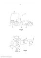
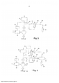
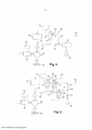
[0030] Em referência aos desenhos anexados, abaixo segue uma descrição em maiores detalhes de concretizações da invenção citadas como exemplos. Nos desenhos: A Figura 1 é uma vista esquemática geral de um veículo equipado com uma disposição de motor de combustão interna que pode ser equipada com um sistema de combustível em concordância com a presente invenção; A Figura 2 é um diagrama esquemático mostrando alguns componentes de uma primeira concretização de um sistema de combustível em concordância com a presente invenção; e: As Figuras 3 até 6 são diagramas esquemáticos mostrando alguns componentes de concretizações adicionais de um sistema de combustível em concordância com a presente invenção.[0030] Referring to the attached drawings, below follows a description in greater detail of embodiments of the invention cited as examples. In the drawings: Figure 1 is a schematic general view of a vehicle equipped with an internal combustion engine arrangement which may be equipped with a fuel system in accordance with the present invention; Figure 2 is a schematic diagram showing some components of a first embodiment of a fuel system in accordance with the present invention; e: Figures 3 through 6 are schematic diagrams showing some components of additional embodiments of a fuel system in accordance with the present invention.
[0031] Na Figura 1 é mostrado um veículo automotivo (10). O veículo automotivo (10) pode ser um caminhão, tal como um trator para reboque de um semitrailer, possuindo um chassi (12) e uma cabine (14) para acomodação de um motorista. Este veículo automotivo (10) compreende uma disposição de motor de combustão interna (16) que inclui um motor de combustão interna (18) e uma instalação de exaustão (20). O motor de combustão interna (18) traciona um conjunto de rodas de tração (22) do veículo automotivo (10), através de uma transmissão apropriada (24).[0031] In Figure 1 an automotive vehicle (10) is shown. The automotive vehicle (10) can be a truck, such as a tractor for towing a semi-trailer, having a chassis (12) and a cabin (14) for accommodating a driver. This automotive vehicle (10) comprises an internal combustion engine arrangement (16) which includes an internal combustion engine (18) and an exhaust installation (20). The internal combustion engine (18) drives a set of drive wheels (22) of the automotive vehicle (10) through a suitable transmission (24).
[0032] De uma maneira conhecida, o motor de combustão interna (18) pode possuir pelo menos um cilindro de motor (não mostrado) no qual combustível é queimado para provocar a movimentação de um pistão (não representado). A movimentação do pistão é transferida para a transmissão (24). O motor pode ser um motor de pistão alternado (recíproco) ou um motor rotativo. Pode ser um motor de ignição por centelha (de ignição por vela) ou um motor de ignição por compressão, tal como um motor Diesel.[0032] In a known manner, the internal combustion engine (18) may have at least one engine cylinder (not shown) in which fuel is burned to cause a piston to move (not shown). The movement of the piston is transferred to the transmission (24). The engine can be an alternating (reciprocal) piston engine or a rotary engine. It can be a spark-ignition (spark-ignition) engine or a compression-ignition engine such as a diesel engine.
[0033] A instalação de exaustão (20) coleta os gases de exaustão produzidos pela combustão de combustível no motor de combustão interna (18), e rejeita os gases de exaustão, por exemplo, para a atmosfera.[0033] The exhaust installation (20) collects the exhaust gases produced by the combustion of fuel in the internal combustion engine (18), and rejects the exhaust gases, for example, into the atmosphere.
[0034] A instalação de exaustão (20) pode incluir um manifold de exaustão e várias tubulações de exaustão. A instalação de exaustão (20) pode incluir um sistema de pós- tratamento de exaustão (26) para redução da quantidade de substâncias nocivas presentes nos gases de exaustão antes que estes venham a ser liberados para a atmosfera; o sistema de pós-tratamento de exaustão (26) pode compreender, inter alia, um ou diversos de um dispositivo de catalisador de oxidação, tal como um dispositivo de catalisador de oxidação de diesel, e/ou de um filtro de particulado, tal como um filtro de particulado de diesel ou DPF, e/ou de um dispositivo de catalisador de redução, tal como um dispositivo de catalisador de redução de NOx (tipicamente um dispositivo de catalisador de redução catalítica seletiva conhecido como dispositivo de SCR), e/ou um dispositivo de catalisador de limpeza para remover sub produtos das reações químicas ocorrendo em um dos dispositivos de catalíticos anteriormente mencionados. A instalação de exaustão pode compreender também um silencioso para redução do ruído transportado (provocado) pelos gases de exaustão.[0034] The exhaust installation (20) may include an exhaust manifold and multiple exhaust pipes. The exhaust installation (20) may include an exhaust after-treatment system (26) for reducing the amount of harmful substances present in the exhaust gases before they are released into the atmosphere; the exhaust aftertreatment system (26) may comprise, inter alia, one or more of an oxidation catalyst device, such as a diesel oxidation catalyst device, and/or a particulate filter, such as a diesel particulate or DPF filter, and/or a reduction catalyst device, such as a NOx reduction catalyst device (typically a selective catalytic reduction catalyst device known as an SCR device), and/or a catalyst cleaning device for removing by-products of chemical reactions taking place in one of the aforementioned catalyst devices. The exhaust installation can also comprise a silencer to reduce the noise carried (caused) by the exhaust gases.
[0035] Para a operação de tais dispositivos de pós-tratamento de exaustão, é em alguns casos necessário proporcionar a instalação de exaustão com combustível. Combustível pode, por exemplo, ser utilizado para produzir calor, por ser queimado ou oxidado, ou ser utilizado como um reagente em uma reação química em um catalisador. Tipicamente, combustível pode ser injetado na corrente de gás de exaustão à montante de um catalisador de oxidação onde o mesmo pode ser oxidado para produzir calor, por exemplo, para regeneração de um filtro de particulado ou para aquecimento dos gases para conseguir uma temperatura de gás adequada para que os mesmos venham a reagir em um catalisador adicional. Combustível pode ser alimentado para um queimador na instalação de exaustão, também para proporcionar calor para os gases de exaustão e para a instalação. Combustível pode ser injetado à montante de um dispositivo de catalisador para reagir em referido dispositivo de catalisador com algumas das substâncias contidas nos gases de exaustão. Por exemplo, a instalação de exaustão pode compreender um bocal de combustível, que pode fazer, ou não fazer, parte de uma unidade de injetor de combustível controlada, para injeção de combustível na instalação de exaustão, por exemplo, em uma tubulação de exaustão ou em uma câmara de misturação da instalação de exaustão.[0035] For the operation of such exhaust aftertreatment devices, it is in some cases necessary to provide the installation of exhaust with fuel. Fuel can, for example, be used to produce heat, by being burned or oxidized, or used as a reactant in a chemical reaction in a catalyst. Typically, fuel can be injected into the exhaust gas stream upstream of an oxidation catalyst where it can be oxidized to produce heat, for example, for regeneration of a particulate filter or for heating the gases to achieve a gas temperature suitable for them to react in an additional catalyst. Fuel can be fed to a burner in the exhaust installation, also to provide heat for the exhaust gases and for the installation. Fuel can be injected upstream of a catalyst device to react in said catalyst device with some of the substances contained in the exhaust gases. For example, the exhaust installation may comprise a fuel nozzle, which may or may not be part of a controlled fuel injector unit, for injecting fuel into the exhaust installation, for example, in an exhaust pipe or in a mixing chamber of the exhaust installation.
[0036] A disposição de motor de combustão interna adicionalmente compreende um sistema de combustível para entrega de combustível pressurizado tanto para o motor de combustão interna (18) e quanto para a instalação de exaustão (20).[0036] The internal combustion engine arrangement additionally comprises a fuel system for delivering pressurized fuel to both the internal combustion engine (18) and the exhaust installation (20).
[0037] Tal sistema de combustível é configurado de maneira tal que combustível é suprido para o pelo menos um cilindro de motor, por uma ramificação de motor do circuito de suprimento de combustível, e de maneira tal que combustível é também suprido para a instalação de exaustão, por uma ramificação de exaustão no circuito de suprimento de combustível. O sistema de combustível é preferivelmente configurado para suprir combustível simultaneamente tanto para o motor de combustão interna e quanto para a instalação de exaustão.[0037] Such a fuel system is configured in such a way that fuel is supplied to the at least one engine cylinder, by an engine branch of the fuel supply circuit, and in such a way that fuel is also supplied to the installation of exhaust, by an exhaust branch in the fuel supply circuit. The fuel system is preferably configured to supply fuel simultaneously to both the internal combustion engine and the exhaust installation.
[0038] O sistema de combustível (28) compreende uma bomba de combustível primária (30), a saída da qual é controlável independentemente da velocidade de motor, isto é, da velocidade do motor de combustão interna (16). Por exemplo, a saída da bomba pode ser alterada sem alteração da velocidade de motor, e/ou a saída da bomba pode ser alterada não proporcionalmente com a velocidade de motor.[0038] The fuel system (28) comprises a primary fuel pump (30), the output of which is controllable independently of the engine speed, that is, the speed of the internal combustion engine (16). For example, pump output can be changed without changing motor speed, and/or pump output can be changed non-proportionally with motor speed.
[0039] A bomba pode, por conseqüência, possuir pelo menos um parâmetro de controle, diferente a partir da velocidade de motor, que pode ser modificado para modificar a saída de bomba.[0039] The pump can, therefore, have at least one control parameter, different from the motor speed, which can be modified to modify the pump output.
[0040] Uma primeira concretização de um tal sistema de combustível irá agora ser descrita em relação para a Figura 2.[0040] A first embodiment of such a fuel system will now be described in relation to Figure 2.
[0041] No exemplo que é mostrado, a bomba de combustível primária (30) é tracionada por um motor elétrico (32). Uma tal bomba eletricamente tracionada (32) pode ser tracionada independentemente da operação do motor, e especialmente independentemente da velocidade de rotação de motor. Em outras palavras, a velocidade da bomba não é ligada para a velocidade do motor por uma relação fixada. Conseqüentemente, a saída da bomba de combustível pode ser ajustada por ajustamento da velocidade do motor elétrico mais preferivelmente do que sendo diretamente tributária da velocidade de motor.[0041] In the example shown, the primary fuel pump (30) is driven by an electric motor (32). Such an electrically driven pump (32) can be driven independently of engine operation, and especially independently of engine rotation speed. In other words, pump speed is not linked to motor speed by a fixed ratio. Consequently, the output of the fuel pump can be adjusted by adjusting the speed of the electric motor more preferably than being directly dependent on the speed of the engine.
[0042] Em uma variante, a bomba de combustível primária (30) poderia ser tracionada por duas fontes de movimentação mecânica, uma sendo a movimentação mecânica do motor de combustão interna e a outra sendo a movimentação mecânica do motor elétrico. Em um tal caso, as movimentações do motor de combustão interna e da máquina elétrica poderiam ser combinadas através de uma engrenagem planetária possuindo uma primeira entrada tracionada pelo motor de combustão interna, uma segunda entrada tracionada pelo motor elétrico e uma saída tracionando a bomba de combustível primária (30). Em um tal sistema, a velocidade da saída tracionando a bomba deveria ser uma combinação linear das velocidades do motor de combustão interna e do motor elétrico, de maneira tal que a velocidade da bomba não é ligada para a velocidade do motor por uma relação fixada, mas pode, ao contrário, ser ajustada graças ao motor elétrico. Em uma variante adicional, a bomba de combustível (30) poderia ser conectada separadamente para o motor de combustão interna e para o motor elétrico através de embreagens que deveriam ser abertas ou fechadas dependendo de qual do motor ou do motor elétrico for escolhido como a fonte de força de tração da bomba. Em uma tal variante, a saída de bomba não é totalmente independente a partir da velocidade de motor, devido para o fato de que uma variação da velocidade de motor irá afetar a saída de bomba se todos os outros parâmetros de controle da bomba forem iguais, mas é, não obstante, independente no sentido de que é possível modificar a saída de bomba utilizando outros parâmetros de controle, tal como a velocidade do motor elétrico, neste caso.[0042] In a variant, the primary fuel pump (30) could be pulled by two sources of mechanical drive, one being the mechanical drive of the internal combustion engine and the other being the mechanical drive of the electric motor. In such a case, the drives of the internal combustion engine and the electric machine could be combined through a planetary gear having a first input driven by the internal combustion engine, a second input driven by the electric motor and an output driving the fuel pump primary (30). In such a system, the output speed driving the pump should be a linear combination of the internal combustion engine and electric motor speeds, such that the pump speed is not linked to the engine speed by a fixed ratio, but, on the contrary, it can be adjusted thanks to the electric motor. In a further variant, the fuel pump (30) could be connected separately to the internal combustion engine and to the electric motor via clutches which should be open or closed depending on which engine or electric motor is chosen as the source. of pulling force of the pump. In such a variant, the pump output is not fully independent from the motor speed, due to the fact that a variation of the motor speed will affect the pump output if all other pump control parameters are equal, but it is nevertheless independent in the sense that it is possible to modify the pump output using other control parameters, such as the speed of the electric motor in this case.
[0043] O motor elétrico poderia ser substituído por qualquer outro tipo de motor independente a partir do motor de combustão interna (16), a velocidade do qual poderia ser alterada para controlar a saída de bomba.[0043] The electric motor could be replaced by any other type of engine independent from the internal combustion engine (16), the speed of which could be changed to control the pump output.
[0044] Em adição, ou alternativamente, a saída da bomba de combustível primária (30) pode ser feita controlável independentemente da velocidade de motor por provisão de uma bomba de capacidade variável, a capacidade da qual pode ser alterada para mudar a saída de bomba. Em um tal caso, controle independente da saída de bomba pode ser conseguido por controle da capacidade de bomba. A bomba pode, então, ser tracionada pelo motor de combustão interna (16), ou por um motor independente, tal como motor elétrico (32).[0044] In addition, or alternatively, the output of the primary fuel pump (30) can be made controllable independently of engine speed by provision of a variable capacity pump, the capacity of which can be changed to change the pump output. . In such a case, independent control of the pump output can be achieved by controlling the pump capacity. The pump can then be driven by the internal combustion engine (16), or by an independent engine such as an electric motor (32).
[0045] Em adição, ou alternativamente, a saída de bomba de combustível primária (30) pode ser feita controlável independentemente da velocidade de motor por provisão de uma bomba tracionada pelo motor de combustão interna através de uma transmissão controlável possuindo relações de velocidade múltiplas, tal como uma caixa de marchas ou uma transmissão continuamente variável, a relação de velocidade da qual pode ser alterada para mudar a saída de bomba. O parâmetro de controle possibilitando controle independente da saída de bomba é, então, a caixa de marchas ou a relação de velocidade de transmissão selecionadas.[0045] In addition, or alternatively, the primary fuel pump output (30) can be made controllable independently of engine speed by provision of a pump driven by the internal combustion engine through a controllable transmission having multiple speed ratios, such as a gearbox or a continuously variable transmission, the speed ratio of which can be changed to change the pump output. The control parameter enabling independent control of the pump output is then the selected gearbox or gear ratio.
[0046] Em uma concretização preferida da presente invenção, a saída de bomba de combustível primária é feita controlável por controle da taxa de fluxo de saída de bomba.[0046] In a preferred embodiment of the present invention, the primary fuel pump output is made controllable by controlling the pump output flow rate.
[0047] A bomba de combustível primária (30) possui uma entrada (34) através da qual a bomba de combustível primária (30) recebe combustível a partir de um tanque de combustível (36). Na concretização que é mostrada da presente invenção, a bomba de combustível primária (30) suga o combustível diretamente a partir do tanque de combustível (36) através de um filtro primário (35). Entretanto, uma bomba de alimentação poderia ser proporcionada entre o tanque de combustível (36) e a bomba de combustível primária (30) para entrega de combustível para a entrada da bomba de combustível primária (30).[0047] The primary fuel pump (30) has an inlet (34) through which the primary fuel pump (30) receives fuel from a fuel tank (36). In the shown embodiment of the present invention, the primary fuel pump (30) sucks fuel directly from the fuel tank (36) through a primary filter (35). However, a feed pump could be provided between the fuel tank (36) and the primary fuel pump (30) for delivering fuel to the inlet of the primary fuel pump (30).
[0048] A bomba de combustível primária (30) possui uma saída (38) através da qual a bomba de combustível primária (30) entrega combustível pressurizado para um circuito de suprimento de combustível (40).[0048] The primary fuel pump (30) has an outlet (38) through which the primary fuel pump (30) delivers pressurized fuel to a fuel supply circuit (40).
[0049] O circuito de suprimento de combustível (40) possui duas ramificações separadas: uma ramificação de motor (42) para entrega de combustível para o motor de combustão interna e uma ramificação de exaustão (44) para entrega de combustível para a instalação de exaustão.[0049] The fuel supply circuit (40) has two separate branches: an engine branch (42) for delivering fuel to the internal combustion engine and an exhaust branch (44) for delivering fuel to the fuel installation. exhaustion.
[0050] Como é mostrado na Figura 1, as duas ramificações (42, 44) podem ser conectadas para a saída de bomba (38) através de uma porção comum (46) do circuito de suprimento de combustível (40). Entretanto, cada ramificação (42, 44) poderia ser separadamente conectada para a saída da bomba primária (30). A porção comum (46) do circuito de suprimento de combustível (40) pode ser equipada com um filtro (48).[0050] As shown in Figure 1, the two branches (42, 44) can be connected to the pump outlet (38) through a common portion (46) of the fuel supply circuit (40). However, each branch (42, 44) could be separately connected to the output of the primary pump (30). The common portion (46) of the fuel supply circuit (40) may be equipped with a filter (48).
[0051] A ramificação de motor (42) do circuito de suprimento de combustível (40) entrega combustível para o/s cilindro/s de motor. A ramificação de motor (42) forma um caminho de fluxo de fluido para combustível a partir da bomba de combustível primária (30) para o/s cilindro/s de motor.[0051] The engine branch (42) of the fuel supply circuit (40) delivers fuel to the engine cylinder/s. The engine branch (42) forms a fluid-to-fuel flow path from the primary fuel pump (30) to the engine cylinder/s.
[0052] A ramificação de motor (42) do circuito de suprimento de combustível (40) pode compreender um estágio de alta pressão (45), com uma ou diversas bombas de alta pressão para pressurização de combustível para níveis de pressão excedendo 100 bars, ou até mesmo excedendo 1.000 bars. O estágio de alta pressão pode ser do tipo de grade comum ou do tipo de injetora-bomba unitária, ou de qualquer outro tipo. A bomba de combustível primária (30) deveria em um tal caso formar uma assim chamada bomba de combustível de baixa pressão para o sistema de combustível. Uma tal bomba de combustível de baixa pressão (30) poderia tipicamente entregar combustível sob uma pressão que é igual a ou abaixo de 20 bars, preferivelmente igual a ou abaixo de 10 bars.[0052] The engine branch (42) of the fuel supply circuit (40) may comprise a high pressure stage (45), with one or several high pressure pumps for pressurizing fuel to pressure levels exceeding 100 bars, or even exceeding 1,000 bars. The high-pressure stage can be of the common grid type or the unit-pump-injector type, or any other type. The primary fuel pump (30) should in such a case form a so-called low pressure fuel pump for the fuel system. Such a low pressure fuel pump (30) would typically deliver fuel at a pressure that is at or below 20 bars, preferably at or below 10 bars.
[0053] A ramificação de motor (42) pode tipicamente possuir pelo menos um injetor, preferivelmente diversos injetores, para injeção de combustível para um manifold de admissão (coletor de admissão) do motor de combustão interna, para injeção de combustível para uma câmara de pré-combustão do motor, ou para injeção do combustível diretamente no/s cilindro/s de motor. A ramificação de motor (42) do circuito de suprimento de combustível (40) pode compreender uma linha de retorno de combustível (não mostrada) para retorno de combustível em excesso para o tanque de combustível (36), e/ou uma linha de recirculação para recirculação do combustível em excesso, por exemplo, para a entrada ou para a saída da bomba de combustível primária (30).[0053] The engine branch (42) may typically have at least one injector, preferably several injectors, for injecting fuel to an inlet manifold (inlet manifold) of the internal combustion engine, for injecting fuel to a chamber. engine pre-combustion, or for injecting fuel directly into the engine cylinder/s. The engine branch (42) of the fuel supply circuit (40) may comprise a fuel return line (not shown) for returning excess fuel to the fuel tank (36), and/or a recirculation line. for recirculating excess fuel, eg to the inlet or outlet of the primary fuel pump (30).
[0054] A ramificação de exaustão (44) do circuito de suprimento de combustível transporta combustível que não é para ser injetado nos cilindros de motor. Em outras palavras, combustível transportado pela ramificação de exaustão (44) irá ser entregue para a instalação de exaustão (20) sem passar através dos cilindros de motor. A ramificação de exaustão (44) forma um caminho de fluxo de fluido para combustível a partir da bomba de combustível primária (30) para a instalação de exaustão (20).[0054] The exhaust branch (44) of the fuel supply circuit carries fuel that is not to be injected into the engine cylinders. In other words, fuel transported by the exhaust branch (44) will be delivered to the exhaust installation (20) without passing through the engine cylinders. The exhaust branch (44) forms a fluid-to-fuel flow path from the primary fuel pump (30) to the exhaust installation (20).
[0055] A ramificação de exaustão (44) e a ramificação de motor (42) são desunidas uma a partir da outra a partir de um ponto de separação (43) que está à montante dos cilindros de motor. Preferivelmente, no caso onde o sistema de combustível possui um estágio de alta pressão, a ramificação de exaustão (44) e a ramificação de motor (42) são desunidas uma a partir da outra a partir de um ponto de separação (43) que está à montante do estágio de alta pressão.[0055] The exhaust branch (44) and the engine branch (42) are separated from each other from a separation point (43) which is upstream of the engine cylinders. Preferably, in the case where the fuel system has a high pressure stage, the exhaust branch (44) and the engine branch (42) are disjoined from each other from a separation point (43) which is upstream of the high pressure stage.
[0056] O circuito de suprimento de combustível (40) pode ser configurado tal como uma variação da saída de bomba de combustível primária (30) resultando em uma correspondente variação da pressão de combustível no circuito de suprimento de combustível (40), especialmente na ramificação de exaustão (44) do circuito de suprimento de combustível (40). Por conseqüência, controle da taxa de fluxo de saída da bomba de combustível primária (30) irá resultar em controle da pressão na ramificação de exaustão (44) do circuito de suprimento de combustível (40).[0056] The fuel supply circuit (40) can be configured as a variation of the primary fuel pump output (30) resulting in a corresponding variation of the fuel pressure in the fuel supply circuit (40), especially in the exhaust branch (44) of the fuel supply circuit (40). Consequently, control of the outflow rate of the primary fuel pump (30) will result in pressure control in the exhaust branch (44) of the fuel supply circuit (40).
[0057] Como pode ser observado na Figura 2, o motor elétrico (32) tracionando a bomba de combustível primária (30) é preferivelmente eletronicamente controlada por um controlador (50). O controlador (50) pode ser uma unidade de controle eletrônico. Um controlador (50) pode tipicamente compreender um ou diversos de um microprocessador, uma memória (RAM e/ou ROM), conexões de entrada e de saída, transceptores para conexão para uma rede por cabo ou para uma rede sem fio, tal como um ônibus CAN, etc. Por conseqüência, o controlador (50) controla a saída da bomba de combustível primária (30).[0057] As can be seen in Figure 2, the electric motor (32) driving the primary fuel pump (30) is preferably electronically controlled by a controller (50). Controller (50) may be an electronic control unit. A controller (50) may typically comprise one or more of a microprocessor, a memory (RAM and/or ROM), input and output connections, transceivers for connection to a cable network or to a wireless network, such as a CAN bus, etc. Consequently, the controller (50) controls the output of the primary fuel pump (30).
[0058] O controlador pode ser um controlador autônomo, ou integrado em um controlador controlando outras funções da disposição de motor de combustão interna (16), especialmente um controlador controlando as principais funções de motor. O controlador (50) pode receber, diretamente ou indiretamente, informação levando em consideração um ou diversos parâmetros de operação da disposição de motor de combustão interna (16), incluindo parâmetros de operação do motor de combustão interna (18), da instalação de exaustão (20) e/ou do veículo ou do equipamento que é tracionado graças para a disposição de motor de combustão interna (16). O controlador pode, por exemplo, ser conectado para um ônibus de dados (databus), tal como um assim chamado ônibus CAN onde tal espécie de informação circula.[0058] The controller can be a standalone controller, or integrated into a controller controlling other functions of the internal combustion engine arrangement (16), especially a controller controlling the main engine functions. The controller (50) can receive, directly or indirectly, information taking into account one or several operating parameters of the internal combustion engine arrangement (16), including operating parameters of the internal combustion engine (18), of the exhaust installation (20) and/or of the vehicle or of the equipment that is towed thanks to the arrangement of an internal combustion engine (16). The controller can, for example, be connected to a data bus (databus) such as a so-called CAN bus where such information circulates.
[0059] A Figura 2 representa uma primeira concretização da ramificação de exaustão (44) de um sistema de combustível em concordância com a presente invenção.[0059] Figure 2 represents a first embodiment of the exhaust branch (44) of a fuel system in accordance with the present invention.
[0060] Neste exemplo, a ramificação de exaustão (44) do circuito de suprimento de combustível (40) compreende uma disposição de válvula de fechamento de combustível de exaustão (52), uma válvula de dosagem de combustível de exaustão (54) e um bocal de exaustão (56) que são dispostos em série, naquele ordenamento ao longo do fluxo de combustível na ramificação de exaustão (44). A ramificação de exaustão (44) compreende tubulações e conduítes adequada/os que podem ser necessários entre os diferentes componentes e para conexão de referidos componentes para a porção comum (46) do circuito de suprimento de combustível (40). Por exemplo, a ramificação de exaustão (44) possui um primeiro membro de tubulação que fluidicamente conecta o ponto de separação (43) para uma porta de entrada da disposição de válvula de fechamento de combustível de exaustão (52), um segundo membro de tubulação que fluidicamente conecta uma porta de saída da disposição de válvula de fechamento de combustível de exaustão (52) para uma porta de entrada da válvula de dosagem de combustível de exaustão (54), e pode compreender um terceiro membro de tubulação que fluidicamente conecta uma porta de saída da válvula de dosagem de combustível de exaustão (54) para o bocal de exaustão (56).[0060] In this example, the exhaust branch (44) of the fuel supply circuit (40) comprises an exhaust fuel shutoff valve arrangement (52), an exhaust fuel metering valve (54) and a exhaust nozzles (56) which are arranged in series in that ordering along the fuel flow in the exhaust branch (44). The exhaust branch (44) comprises suitable piping and conduit which may be required between the different components and for connecting said components to the common portion (46) of the fuel supply circuit (40). For example, the exhaust branch (44) has a first piping member that fluidly connects the separation point (43) to an inlet port of the exhaust fuel shutoff valve arrangement (52), a second piping member which fluidly connects an outlet port of the fuel exhaust shutoff valve arrangement (52) to an inlet port of the metering exhaust fuel valve (54), and may comprise a third piping member that fluidly connects a port. from the exhaust fuel metering valve (54) to the exhaust nozzle (56).
[0061] O bocal de exaustão (56) é proporcionado para injetar combustível na instalação de exaustão, por exemplo, diretamente em uma tubulação de exaustão ou em uma câmara de misturação onde flui um fluxo de gases de exaustão coletados a partir do/s cilindro/s de motor, ou em um aparelho pertencendo para a instalação de exaustão, tal como um dispositivo de catalisador, um queimador de combustível, etc. O bocal de exaustão (56) é preferivelmente um componente passivo, isto é, um componente que não é eletronicamente controlado. Em sua forma a mais simples, o bocal de exaustão (56) pode ser um corpo possuindo uma cavidade para a qual combustível é entregue a partir dos outros componentes da ramificação de exaustão (44), referida cavidade possuindo um ou diversos orifícios calibrados.[0061] The exhaust nozzle (56) is provided to inject fuel into the exhaust installation, for example, directly into an exhaust pipe or a mixing chamber where a flow of exhaust gases collected from the cylinder/s flows /s of engine, or in an appliance belonging to the exhaust installation, such as a catalyst device, a fuel burner, etc. The exhaust nozzle (56) is preferably a passive component, i.e. a component that is not electronically controlled. In its simplest form, the exhaust nozzle (56) may be a body having a cavity into which fuel is delivered from the other components of the exhaust branch (44), said cavity having one or several calibrated holes.
[0062] A válvula de dosagem de combustível de exaustão (54) controla a quantidade de combustível entregue através do bocal de exaustão (56). Nesta concretização da presente invenção, é uma válvula eletromagneticamente controlada, por exemplo, uma válvula solenóide, que pode controlar a temporização de injeção de combustível através do bocal de exaustão (56). Pode ser uma simples válvula de liga/desliga (on/off), ou uma válvula proporcionalmente controlada para controlar o fluxo e/ou a pressão de combustível entregue pela ramificação de exaustão (44) através do bocal de exaustão (56). A válvula de dosagem de combustível de exaustão (54) pode ser controlada por modulação de largura de pulso. Preferivelmente, se conhecem tempos de abertura e de fechamento para precisamente controlar a quantidade de combustível entregue através do bocal de exaustão (56). Esta quantidade de combustível pode ser controlada pelo controlador (50) ou por um outro controlador, incluindo um controlador dedicado.[0062] The exhaust fuel metering valve (54) controls the amount of fuel delivered through the exhaust nozzle (56). In this embodiment of the present invention, it is an electromagnetically controlled valve, for example a solenoid valve, which can control the fuel injection timing through the exhaust nozzle (56). It can be a simple on/off valve, or a proportionally controlled valve to control the flow and/or pressure of fuel delivered by the exhaust branch (44) through the exhaust nozzle (56). The exhaust fuel metering valve (54) can be controlled by pulse width modulation. Preferably, opening and closing times are known to precisely control the amount of fuel delivered through the exhaust nozzle (56). This amount of fuel can be controlled by the controller (50) or by another controller including a dedicated controller.
[0063] A válvula de dosagem de combustível de exaustão (54) e o bocal de exaustão (56) podem ser unidos em um corpo unitário formando uma unidade de injetor controlada integrada. Alternativamente, a válvula de dosagem de combustível de exaustão (54) e o bocal de exaustão (56) podem ser entidades físicas separadas fluidicamente conectadas por um conduíte de combustível.[0063] The exhaust fuel metering valve (54) and the exhaust nozzle (56) can be joined in a unitary body forming an integrated controlled injector unit. Alternatively, the exhaust fuel metering valve (54) and the exhaust nozzle (56) may be separate physical entities fluidly connected by a fuel conduit.
[0064] A disposição de válvula de fechamento de combustível de exaustão (52) controla o fluxo de combustível na ramificação de exaustão (44) do circuito de suprimento de combustível (40). Esta disposição de válvula de fechamento de combustível de exaustão (52) pode vantajosamente ser uma disposição de válvula de fechamento hidraulicamente controlada que é forçada para permutar entre um estado aberto e um estado fechado dependendo da pressão de combustível no circuito de suprimento de combustível (40) comparada com uma pressão de limiar.[0064] The fuel exhaust shutoff valve arrangement (52) controls the flow of fuel in the exhaust branch (44) of the fuel supply circuit (40). This exhaust fuel shutoff valve arrangement (52) may advantageously be a hydraulically controlled shutoff valve arrangement which is forced to switch between an open state and a closed state depending on the fuel pressure in the fuel supply circuit (40 ) compared to a threshold pressure.
[0065] Na concretização da Figura 2, uma função desta disposição de válvula pode ser aquela de uma válvula de segurança que irá ser utilizada para prevenir qualquer injeção de combustível indesejada no sistema de exaustão até mesmo se a válvula de dosagem de combustível de exaustão (54) permanece bloqueada em uma posição aberta.[0065] In the embodiment of Figure 2, a function of this valve arrangement may be that of a safety valve that will be used to prevent any unwanted fuel injection into the exhaust system even if the exhaust fuel metering valve ( 54) remains locked in an open position.
[0066] A disposição de válvula de fechamento de combustível (52) pode ser configurada de uma maneira tal que a mesma é forçada para abrir quando a pressão à montante da válvula de fechamento de combustível excede uma pressão de limiar.[0066] The fuel shutoff valve arrangement (52) may be configured in such a way that it is forced to open when the pressure upstream of the fuel shutoff valve exceeds a threshold pressure.
[0067] Por exemplo, a disposição de válvula de fechamento de combustível de exaustão (52) pode possuir uma porta de controle hidráulico (58) que é fluidicamente conectada para o circuito de suprimento de combustível (40). Em um tal caso, a pressão de controle que irá determinar o estado da disposição de válvula de fechamento é diretamente relacionado, preferivelmente proporcional, e o mais preferivelmente igual, para a pressão de combustível entregue pela bomba de combustível primária (30). Vantajosamente, o estado aberto ou fechado da válvula de fechamento pode ser modificado por controle da saída da bomba de combustível primária (30).[0067] For example, the fuel exhaust shutoff valve arrangement (52) may have a hydraulic control port (58) that is fluidly connected to the fuel supply circuit (40). In such a case, the control pressure that will determine the state of the shut-off valve arrangement is directly related, preferably proportional, and most preferably equal, to the fuel pressure delivered by the primary fuel pump (30). Advantageously, the open or closed state of the closing valve can be modified by controlling the output of the primary fuel pump (30).
[0068] Mais precisamente, a porta de controle hidráulico (58) da válvula de fechamento de combustível de exaustão (52) pode ser conectada para a ramificação de exaustão (44) do circuito de suprimento de combustível (40), isto é, à jusante do ponto de separação (43) onde a ramificação de exaustão (44) do circuito de suprimento de combustível (40) se desune a partir da ramificação de motor (42). Entretanto, na concretização que é mostrada, a porta de controle hidráulico (58) da válvula de fechamento de combustível de exaustão (52) é conectada para a ramificação de exaustão (44) à montante da válvula de fechamento de combustível de exaustão (52).[0068] More precisely, the hydraulic control port (58) of the exhaust fuel shutoff valve (52) can be connected to the exhaust branch (44) of the fuel supply circuit (40), i.e., to the downstream of the separation point (43) where the exhaust branch (44) of the fuel supply circuit (40) disconnects from the engine branch (42). However, in the embodiment shown, the hydraulic control port (58) of the exhaust fuel shutoff valve (52) is connected to the exhaust branch (44) upstream of the exhaust fuel shutoff valve (52) .
[0069] A porta de controle hidráulico (58) pode ser de fato conectada para a porta de entrada da válvula de fechamento de combustível de exaustão (52) por um conduíte integralmente formado no corpo de válvula, por conseqüência, não requerendo nenhuma tubulação externa adicional.[0069] The hydraulic control port (58) can actually be connected to the inlet port of the exhaust fuel shutoff valve (52) by a conduit integrally formed in the valve body, therefore requiring no external piping additional.
[0070] A disposição de válvula de fechamento de combustível de exaustão (52) é preferivelmente uma disposição de válvula passiva, isto é, um componente que não é eletronicamente controlado. Na concretização que é mostrada, a disposição de válvula de fechamento de combustível de exaustão (52) compreende uma única válvula de fechamento hidraulicamente controlada. Pode ser, como é mostrado, uma válvula de 2 (duas) posições possuindo uma entrada e uma saída, onde uma posição corresponde para o estado aberto da válvula, com a entrada sendo fluidicamente conectada para a saída, e a outra posição corresponde para o estado fechado da válvula, com a entrada sendo fluidicamente desconectada a partir da saída. A válvula de fechamento de combustível de exaustão (52) pode ser uma válvula com um núcleo de válvula de deslizamento linearmente deslizando entre uma posição aberta e uma posição fechada. Entretanto, um outro tipo de válvula ou uma combinação de válvulas podem ser utilizado/as para formar a disposição de válvula.[0070] The fuel exhaust shutoff valve arrangement (52) is preferably a passive valve arrangement, i.e. a component that is not electronically controlled. In the embodiment shown, the fuel exhaust shutoff valve arrangement (52) comprises a single hydraulically controlled shutoff valve. It can be, as shown, a 2 (two) position valve having an inlet and an outlet, where one position corresponds to the open state of the valve, with the inlet being fluidly connected to the outlet, and the other position corresponds to the closed state of the valve, with the inlet being fluidly disconnected from the outlet. The exhaust fuel shutoff valve (52) may be a valve with a linearly slide valve core sliding between an open position and a closed position. However, another type of valve or a combination of valves can be used to form the valve arrangement.
[0071] Na concretização que é mostrada, a válvula de fechamento de combustível de exaustão hidraulicamente controlada (52) é elasticamente inclinada em direção de uma posição fechada, por exemplo, por uma mola atuando sobre uma lateral do núcleo de válvula, contra a ação da pressão em sua porta de controle hidráulico (58) que pode exercer sua força contra a outra lateral do núcleo de válvula. A válvula é configurada de maneira tal que se a pressão em sua porta de controle hidráulico (58) é inferior para uma pressão de limiar, a mola mantém a válvula em uma primeira posição, aqui a posição de fechamento onde nenhum combustível pode passar através da válvula, e, se a pressão em sua porta de controle hidráulico (58) é superior para uma pressão de limiar, então, a ação de pressão força a válvula para uma segunda posição, aqui a posição aberta onde combustível pode fluir através da válvula de fechamento de combustível de exaustão hidraulicamente controlada (52). Como é observada a partir de cima, a válvula de fechamento de combustível de exaustão hidraulicamente controlada (52) na Figura 2 é uma válvula normalmente fechada de maneira tal que na ausência de pressão em sua porta de controle hidráulico (58), a válvula de fechamento de combustível de exaustão hidraulicamente controlada (52) fecha a entrega de combustível.[0071] In the embodiment shown, the hydraulically controlled exhaust fuel shutoff valve (52) is elastically inclined toward a closed position, for example, by a spring acting on one side of the valve core, against action of pressure in its hydraulic control port (58) which can exert its force against the other side of the valve core. The valve is configured in such a way that if the pressure at its hydraulic control port (58) is less than a threshold pressure, the spring holds the valve in a first position, here the closing position where no fuel can pass through the valve, and if the pressure at its hydraulic control port (58) is higher for a threshold pressure, then the pressure action forces the valve to a second position, here the open position where fuel can flow through the valve. hydraulically controlled exhaust fuel shutoff (52). As seen from above, the hydraulically controlled exhaust fuel shutoff valve (52) in Figure 2 is a normally closed valve such that in the absence of pressure at its hydraulic control port (58), the hydraulically controlled exhaust fuel shutoff (52) shuts off fuel delivery.
[0072] Um método para controle da bomba de combustível primária pode incluir as seguintes etapas: - controle da saída de bomba de combustível primária (30) de maneira tal que a pressão de combustível entregue pela bomba de combustível primária (30) no circuito de suprimento de combustível (40) permanece abaixo de uma primeira pressão de limiar quando nenhum combustível é para ser entregue para a instalação de exaustão (20); e: - controle da saída de bomba de combustível primária (30) de maneira tal que a pressão de combustível entregue pela bomba de combustível primária (30) no circuito de suprimento de combustível (40) excede uma segunda pressão de limiar quando combustível é para ser entregue para a instalação de exaustão (20).[0072] A method for controlling the primary fuel pump may include the following steps: - controlling the primary fuel pump output (30) in such a way that the fuel pressure is delivered by the primary fuel pump (30) in the fuel circuit. fuel supply (40) remains below a first threshold pressure when no fuel is to be delivered to the exhaust facility (20); and: - controlling the primary fuel pump output (30) such that the fuel pressure delivered by the primary fuel pump (30) in the fuel supply circuit (40) exceeds a second threshold pressure when fuel is stopped. be delivered to the exhaust installation (20).
[0073] A primeira pressão de limiar e a segunda pressão de limiar podem ser iguais. A primeira pressão de limiar e a segunda pressão de limiar são, então, preferivelmente iguais para a pressão de limiar na qual a disposição de válvula de fechamento de combustível hidraulicamente controlada permuta a partir de entre seu estado aberto e seu estado fechado. Alternativamente, a segunda pressão de limiar pode ser mais alta do que a primeira pressão de limiar. Em um tal caso, a pressão de limiar na qual a disposição de válvula de fechamento de combustível hidraulicamente controlada permuta a partir de entre seu estado aberto e seu estado fechado é preferivelmente compreendida entre a primeira pressão de limiar e a segunda pressão de limiar.[0073] The first threshold pressure and the second threshold pressure can be the same. The first threshold pressure and the second threshold pressure are then preferably equal to the threshold pressure at which the hydraulically controlled fuel shut-off valve arrangement switches from between its open state and its closed state. Alternatively, the second threshold pressure can be higher than the first threshold pressure. In such a case, the threshold pressure at which the hydraulically controlled fuel shut-off valve arrangement switches from between its open state and its closed state is preferably comprised between the first threshold pressure and the second threshold pressure.
[0074] um método para controle de uma bomba de combustível primária pode incluir a etapa de variação da pressão de combustível entregue pela bomba de combustível primária (30) no circuito de suprimento de combustível (40) dentro de uma baixa faixa dependendo dos requerimentos de entrega de combustível no motor de combustão interna, em que referida baixa faixa está abaixo da pressão de limiar na qual a disposição de válvula de fechamento de combustível hidraulicamente controlada permuta a partir de entre seu estado aberto e seu estado fechado.[0074] A method for controlling a primary fuel pump may include the step of varying the fuel pressure delivered by the primary fuel pump (30) in the fuel supply circuit (40) within a low range depending on fuel requirements. fuel delivery in the internal combustion engine, wherein said low range is below the threshold pressure at which the hydraulically controlled fuel shut-off valve arrangement switches from between its open state and its closed state.
[0075] Tais métodos de controle possibilitam controle indireto da disposição de válvula de fechamento de combustível hidraulicamente controlada. Tais métodos podem ser implementados pelo controlador (50).[0075] Such control methods enable indirect control of the hydraulically controlled fuel shutoff valve arrangement. Such methods can be implemented by the controller (50).
[0076] Por exemplo, a válvula de fechamento de combustível de exaustão (52) pode ser configurada para permutar a partir do estado fechado para o estado aberto em uma pressão de limiar de 7 bars. Em um tal caso, quando nenhum combustível é para ser entregue para a instalação de exaustão, o motor elétrico (32) tracionando a bomba de combustível primária (30) pode ser controlado pelo controlador (50) de maneira tal que a bomba gera no circuito de suprimento de combustível (40) um nível de baixa pressão que pode estar, por exemplo, em uma baixa faixa de 3 bars até 6 bars, isto é, abaixo da pressão de limiar. Este nível de baixa pressão pode ser fixado, ou pode variar dentro da baixa faixa, por exemplo, dependendo dos parâmetros de operação de motor. Quando o combustível é para ser entregue para a instalação de exaustão, o motor elétrico (32) tracionando a bomba de combustível primária (30) pode ser controlado pelo controlador (50) de maneira tal que a bomba de combustível primária (30) gera no circuito de suprimento de combustível (40) uma pressão mais alta que pode ser, por exemplo, superior a 7 bars, ou superior a 8 bars dependendo de qualquer incerteza sobre o valor exato da pressão de limiar. Isto pode ser conseguido por aumento da velocidade na qual a bomba de combustível primária é tracionada. Isto provoca que a válvula de fechamento de combustível de exaustão (52) venha a permutar a partir do estado fechado para o estado aberto, possibilitando que combustível venha a alcançar a válvula de dosagem de combustível de exaustão (54). Controle da quantidade de combustível efetivamente entregue para a instalação de exaustão pode, então, ser desempenhado por controle apropriado da válvula de dosagem de combustível de exaustão (54). O nível de pressão mais alta entregue pela bomba de combustível primária (30) pode ser um valor pré- determinado fixado, por exemplo, de 8 bars, ou pode variar dentro de uma faixa mais alta, por exemplo entre 8 bars e 10 bars. Quando combustível não é mais de nenhuma forma necessitado na instalação de exaustão, o controlador (50) controla o motor elétrico (32) de maneira tal a reduzir a saída da bomba de combustível primária (30) de volta para um valor de baixa pressão, inferior para a pressão de limiar de 7 bars.[0076] For example, the exhaust fuel shutoff valve (52) can be configured to switch from the closed state to the open state at a threshold pressure of 7 bars. In such a case, when no fuel is to be delivered to the exhaust installation, the electric motor (32) pulling the primary fuel pump (30) can be controlled by the controller (50) in such a way that the pump generates in the circuit. of fuel supply (40) a low pressure level which can be, for example, in a low range of 3 bar to 6 bar, ie below the threshold pressure. This low pressure level can be fixed, or it can vary within the low range, for example, depending on engine operating parameters. When fuel is to be delivered to the exhaust installation, the electric motor (32) driving the primary fuel pump (30) can be controlled by the controller (50) in such a way that the primary fuel pump (30) generates on the fuel supply circuit (40) a higher pressure which can be, for example, greater than 7 bars, or greater than 8 bars depending on any uncertainty about the exact value of the threshold pressure. This can be achieved by increasing the speed at which the primary fuel pump is pulled. This causes the exhaust fuel shutoff valve (52) to switch from the closed state to the open state, enabling fuel to reach the exhaust fuel metering valve (54). Control of the amount of fuel actually delivered to the exhaust facility can then be accomplished by properly controlling the exhaust fuel metering valve (54). The highest pressure level delivered by the primary fuel pump (30) can be a fixed predetermined value, for example 8 bars, or it can vary within a higher range, for example between 8 bars and 10 bars. When fuel is no longer needed at all in the exhaust installation, the controller (50) controls the electric motor (32) in such a way as to reduce the output of the primary fuel pump (30) back to a low pressure value, lower for threshold pressure of 7 bar.
[0077] Pode ser observado que quando a bomba é operada para entregar pressão acima da pressão de limiar, a mesma pressão é entregue para a ramificação de motor (42) do circuito de suprimento de combustível (40), embora tal pressão mais alta não seja necessitada na ramificação de motor (42). Isto pode acontecer independentemente das necessidades operacionais do motor. Na maior parte dos casos, especialmente no caso em que existe um estágio de alta pressão na ramificação de motor (42), a pressão mais alta entregue pela bomba de combustível primária (30) não irá mudar o funcionamento do motor. Entretanto, em algumas configurações, poderia ser útil ou até mesmo necessário instalar um limitador de pressão na ramificação de motor (44).[0077] It can be seen that when the pump is operated to deliver pressure above the threshold pressure, the same pressure is delivered to the engine branch (42) of the fuel supply circuit (40), although such higher pressure does not is needed in the engine branch (42). This can happen regardless of the engine's operating needs. In most cases, especially in the case where there is a high pressure stage in the engine branch (42) the higher pressure delivered by the primary fuel pump (30) will not change engine operation. However, in some configurations it might be useful or even necessary to install a pressure limiter on the engine branch (44).
[0078] Graças ao que foi anteriormente mencionado, a disposição de válvula de fechamento de combustível de exaustão (52) pode ser controlada unicamente pelo controle da saída da bomba de combustível primária (30), sem em si mesma sendo uma disposição de válvula eletronicamente controlada, isto é, sem compreender uma válvula solenóide.[0078] Thanks to the foregoing, the exhaust fuel shutoff valve arrangement (52) can be controlled solely by controlling the output of the primary fuel pump (30), without itself being an electronically valve arrangement controlled, that is, without comprising a solenoid valve.
[0079] Uma segunda concretização de um sistema de combustível em concordância com a presente invenção é mostrada na Figura 3 onde a única diferença se baseia em que não existe mais de nenhuma forma uma válvula de dosagem de combustível de exaustão na ramificação de exaustão (44) do circuito de suprimento de combustível (40). Ao invés disso, uma restrição de fluxo (60) é proporcionada na ramificação de exaustão (44), preferivelmente à jusante da disposição de válvula de fechamento de combustível de exaustão (52). A restrição de fluxo (60) pode ser um orifício calibrado. Esta restrição de fluxo pode estar à montante do bocal de exaustão (56), ou dentro do bocal de exaustão (56), ou esta restrição de fluxo poderia ser integrada na disposição de válvula de fechamento de combustível de exaustão (52). A restrição de fluxo pode ser feita de fato pelo/s orifício/s de saída do bocal de exaustão (56). Todos os outros componentes podem ser idênticos para aqueles verificados na concretização da Figura 2 de maneira tal que sua descrição não irá ser repetida.[0079] A second embodiment of a fuel system in accordance with the present invention is shown in Figure 3 where the only difference is that there is no longer an exhaust fuel metering valve in the exhaust branch at all (44 ) of the fuel supply circuit (40). Instead, a flow restriction (60) is provided in the exhaust branch (44), preferably downstream of the exhaust fuel shutoff valve arrangement (52). The flow restriction (60) may be a calibrated orifice. This flow restriction could be upstream of the exhaust nozzle (56), or within the exhaust nozzle (56), or this flow restriction could be integrated into the fuel exhaust shutoff valve arrangement (52). The flow restriction can be done in fact through the outlet port(s) of the exhaust nozzle (56). All other components may be identical to those found in the Figure 2 embodiment in such a way that their description will not be repeated.
[0080] Nesta concretização da presente invenção, tão prontamente quanto a disposição de válvula de fechamento de combustível de exaustão (52) permuta para seu estado aberto sobre controle apropriado da saída de bomba de combustível primária (30), combustível é entregue para a instalação de exaustão através do bocal de exaustão (56). Em um tal caso, a taxa de fluxo de combustível entregue para a instalação de exaustão pode ser controlada por controle apropriado da saída de bomba de combustível primária (30), tal como por controle da velocidade do motor elétrico (32) tracionando a bomba de combustível primária (30). Por exemplo, para uma primeira velocidade da bomba pode corresponder para uma pressão de combustível de 8 bars na ramificação de exaustão (44), o que envolve uma primeira taxa de fluxo através da restrição de fluxo (60), enquanto para uma segunda velocidade da bomba pode corresponder para uma pressão de 10 bars na ramificação de exaustão (44), o que pode envolver uma segunda taxa de fluxo através da restrição de fluxo (60). Fundamentada sobre a taxa de fluxo, por conseqüência, obtida, a quantidade de combustível global entregue pode ser controlada por controle do tempo de abertura da válvula de fechamento de combustível de exaustão (52), isto sendo conseguido por controle da quantidade de tempo em que a pressão na ramificação de exaustão (44) é mantida acima da pressão de limiar por controle apropriado da saída de bomba de combustível primária (30).[0080] In this embodiment of the present invention, as readily as the exhaust fuel shutoff valve arrangement (52) switches to its open state under proper control of the primary fuel pump outlet (30), fuel is delivered to the facility exhaust through the exhaust nozzle (56). In such a case, the fuel flow rate delivered to the exhaust facility may be controlled by appropriate control of the primary fuel pump output (30), such as by controlling the speed of the electric motor (32) driving the fuel pump. primary fuel (30). For example, for a first pump speed this can correspond to a fuel pressure of 8 bars in the exhaust branch (44), which involves a first flow rate through the flow restriction (60), while for a second pump speed. pump can correspond to a pressure of 10 bar in the exhaust branch (44), which can involve a second flow rate through the flow restriction (60). Based on the flow rate, therefore, obtained, the quantity of global fuel delivered can be controlled by controlling the opening time of the exhaust fuel closing valve (52), this being achieved by controlling the amount of time in which the pressure in the exhaust branch (44) is maintained above the threshold pressure by appropriate control of the primary fuel pump outlet (30).
[0081] Em outras palavras, um método para controle da bomba de combustível primária (30) pode incluir a etapa de variação da pressão de combustível entregue pela bomba de combustível primária (30) no circuito de suprimento de combustível (40) dentro de uma alta faixa dependendo dos requerimentos de entrega de combustível da instalação de exaustão, em que referida alta faixa está acima da pressão de limiar na qual a disposição de válvula de fechamento de combustível de exaustão hidraulicamente controlada (52) permuta a partir de entre seu estado aberto e seu estado fechado.[0081] In other words, a method for controlling the primary fuel pump (30) may include the step of varying the fuel pressure delivered by the primary fuel pump (30) in the fuel supply circuit (40) within a high range depending on the fuel delivery requirements of the exhaust facility, wherein said high range is above the threshold pressure at which the hydraulically controlled exhaust fuel shut-off valve arrangement (52) switches from its open state and its closed state.
[0082] Na concretização que é mostrada na Figura 2 onde controle preciso da taxa de fluxo entregue para a instalação de exaustão é conseguido com a válvula de dosagem de combustível de exaustão (54), pode não ser necessário possuir um controle muito preciso da pressão efetiva no circuito de suprimento de combustível (40). Conseqüentemente, controle da saída de bomba de combustível primária (30) não tem necessidade de ser muito preciso, e por conseqüência, pode não haver a necessidade para um sensor de pressão na ramificação de exaustão (44) do circuito de suprimento de combustível (40). Tudo que pode ser necessitado pode ser uma saída pré-definida, por exemplo, a velocidade alvo, da bomba de combustível primária (30) que, sobre calibragem de sistema, mostra que a pressão requerida, acima da pressão de limiar de permutação de válvula, é obtida na desejada faixa de condições de operação.[0082] In the embodiment shown in Figure 2 where precise control of the flow rate delivered to the exhaust installation is achieved with the exhaust fuel metering valve (54), it may not be necessary to have very accurate pressure control effective in the fuel supply circuit (40). Consequently, control of the primary fuel pump output (30) does not need to be very accurate, and consequently, there may not be a need for a pressure sensor in the exhaust branch (44) of the fuel supply circuit (40 ). All that may be needed can be a pre-set output, for example the target speed, of the primary fuel pump (30) which, upon system calibration, shows that the required pressure, above the valve permutation threshold pressure , is obtained in the desired range of operating conditions.
[0083] Na concretização que é mostrada na Figura 3, para melhor precisão, pode ser de utilidade ou de necessidade possuir um sensor de pressão (64) no circuito de suprimento de combustível (40), por exemplo, na ramificação de exaustão (44). A informação de pressão entregue por aquele sensor de pressão (64) pode ser realimentada para o controlador (50). A saída de bomba de combustível primária (30), neste caso controlada através da velocidade na qual a bomba de combustível primária (30) é tracionada pelo motor elétrico (32), pode ser realimentada controlada pelo controlador (50) para alcançar tão precisamente quanto possível um determinado nível de pressão que corresponde para uma desejada taxa de fluxo através da ramificação de exaustão (44) quando a disposição de válvula de fechamento de combustível de exaustão (52) está em seu estado aberto. Um tal sensor de pressão (64) pode ser instalado na ramificação de exaustão (44) á montante da válvula de fechamento de combustível de exaustão (52). Entretanto, outras localizações podem ser proporcionadas para o sensor de pressão (64), incluindo à jusante da disposição de válvula de fechamento de combustível de exaustão (52) ou na ramificação de motor (42). Tal disposição de sensor de pressão pode também ser utilizada em um sistema tal como aquele que é mostrado na Figura 2.[0083] In the embodiment shown in Figure 3, for better accuracy, it may be useful or necessary to have a pressure sensor (64) in the fuel supply circuit (40), for example, in the exhaust branch (44 ). The pressure information delivered by that pressure sensor (64) can be fed back to the controller (50). The primary fuel pump output (30), in this case controlled by the speed at which the primary fuel pump (30) is driven by the electric motor (32), can be feedback controlled by the controller (50) to achieve as precisely as A certain pressure level corresponding to a desired flow rate through the exhaust branch (44) is possible when the exhaust fuel shutoff valve arrangement (52) is in its open state. Such a pressure sensor (64) may be installed in the exhaust branch (44) upstream of the exhaust fuel shutoff valve (52). However, other locations may be provided for the pressure sensor (64), including downstream of the exhaust fuel shutoff valve arrangement (52) or on the engine branch (42). Such a pressure sensor arrangement can also be used in a system such as the one shown in Figure 2.
[0084] [0088] Uma terceira concretização de um sistema de combustível em concordância com a presente invenção agora irá ser descrita em relação para a Figura 4. Esta terceira concretização da presente invenção é fundamentada sobre a primeira concretização da presente invenção descrita em relação para a Figura 2, de maneira tal que tudo aquilo que foi descrito em relação para a concretização da Figura 2 se aplica para esta terceira concretização da presente invenção e não irá ser repetido.[0084] [0088] A third embodiment of a fuel system in accordance with the present invention will now be described in relation to Figure 4. This third embodiment of the present invention is based on the first embodiment of the present invention described in relation to Figure 2, in such a way that all that has been described in relation to the embodiment of Figure 2 applies to this third embodiment of the present invention and will not be repeated.
[0085] A concretização de um sistema de combustível da presente invenção em concordância com a Figura 4 adicionalmente compreende um sistema de purga (66), por exemplo, para purga de pelo menos parte da ramificação de exaustão (44) do circuito de suprimento de combustível (40) quando nenhum combustível é para ser entregue para a instalação de exaustão. Sem dúvida, a ramificação de exaustão (44) é operativa somente intermitentemente, somente sob determinadas condições de operação de motor. Pelo restante do tempo, nenhum combustível flui na ramificação de exaustão (44). Durante aqueles períodos de tempo, o combustível contido na ramificação de exaustão (44) pode ser submetido para degradação. Por exemplo, o bocal de exaustão (56) pode ser fechado para a linha de exaustão na qual gases de exaustão quentes fluem e podem, conseqüentemente, serem submetidos para temperaturas bastante altas. O combustível aprisionado no bocal de exaustão (56) pode ser submetido para cozimento, o que traz (introduz) depósitos de substâncias de carbono no interior do bocal de exaustão (56), o que pode provocar que o bocal de exaustão (56) venha a se tornar entupido ou parcialmente entupido.[0085] The embodiment of a fuel system of the present invention in accordance with Figure 4 further comprises a purge system (66), for example, for purging at least part of the exhaust branch (44) of the fuel supply circuit. fuel (40) when no fuel is to be delivered to the exhaust facility. Of course, exhaust branch (44) is operative only intermittently, only under certain engine operating conditions. For the remainder of the time, no fuel flows into the exhaust branch (44). During those time periods, the fuel contained in the exhaust branch (44) may be subjected to degradation. For example, the exhaust nozzle (56) can be closed to the exhaust line in which hot exhaust gases flow and can consequently be subjected to very high temperatures. The fuel trapped in the exhaust nozzle (56) can be subjected to cooking, which brings (introduces) deposits of carbon substances inside the exhaust nozzle (56), which can cause the exhaust nozzle (56) to come to become clogged or partially clogged.
[0086] O sistema de purga (66) compreende uma disposição de válvula de controle de purga (68) que possui uma entrada (70) conectável para uma fonte de fluido de purga pressurizada (72) e uma saída (74) que é conectada para a ramificação de exaustão (44) do circuito de suprimento de combustível (40), preferivelmente à montante do bocal de exaustão (56) para injeção de combustível para uma corrente de gás de exaustão. A fonte de fluido de purga pressurizada (72) pode ser uma fonte de gás pressurizado, por exemplo, uma fonte de ar sob pressão. Embarcado em alguns veículos, tais como caminhões comerciais pesados, existe freqüentemente pelo menos um reservatório de ar pressurizado que é proporcionado, por exemplo, para a operação de sistemas de freio pneumaticamente operados, e que poderiam ser utilizados como a fonte de fluido de purga pressurizada.[0086] The purge system (66) comprises a purge control valve arrangement (68) that has an inlet (70) connectable to a source of pressurized purge fluid (72) and an outlet (74) that is connected to the exhaust branch (44) of the fuel supply circuit (40), preferably upstream of the exhaust nozzle (56) for injecting fuel into an exhaust gas stream. The source of pressurized purge fluid (72) can be a source of pressurized gas, e.g., a source of pressurized air. Embedded in some vehicles, such as heavy commercial trucks, there is often at least one pressurized air reservoir which is provided, for example, for operating pneumatically operated brake systems, and which could be used as the source of pressurized purge fluid .
[0087] No sistema que é mostrado na Figura 4, a saída (74) da disposição de válvula de controle de purga (68) é conectada por uma tubulação de purga (76) para a válvula de dosagem de combustível de exaustão (54), com vistas a se ter capacidade de purga de combustível a partir de pelo menos parte da válvula de dosagem de combustível de exaustão (54) e a partir do bocal de exaustão (56). Mais precisamente, em uma concretização preferida da presente invenção, a tubulação de purga (76) pode ser conectada para uma lateral à montante da válvula de dosagem de combustível de exaustão (54), de maneira tal que quando a válvula de dosagem de combustível de exaustão (54) está em um estado fechado, nenhum fluido de purga pode fluir em direção do bocal de exaustão (56).[0087] In the system that is shown in Figure 4, the outlet (74) of the purge control valve arrangement (68) is connected by a purge piping (76) to the exhaust fuel metering valve (54) , in order to have the ability to purge fuel from at least part of the exhaust fuel metering valve (54) and from the exhaust nozzle (56). More precisely, in a preferred embodiment of the present invention, the bleed piping (76) may be connected to an upstream side of the exhaust fuel metering valve (54), such that when the exhaust fuel metering valve exhaust (54) is in a closed state, no purge fluid can flow towards the exhaust nozzle (56).
[0088] Uma válvula de verificação (80) pode ser instalada na ramificação de exaustão (44) do circuito de suprimento de combustível (40), à montante de sua conexão para o sistema de purga (66), para prevenir qualquer fluxo de retorno de ar de purga na direção à montante na ramificação de exaustão (44). No exemplo da Figura 4, a válvula de verificação (80) pode ser localizada na entrada de combustível da válvula de dosagem de combustível de exaustão (54).[0088] A check valve (80) can be installed in the exhaust branch (44) of the fuel supply circuit (40), upstream of its connection to the purge system (66), to prevent any backflow of purge air in the upstream direction in the exhaust branch (44). In the example of Figure 4, the check valve (80) can be located on the fuel inlet of the exhaust fuel metering valve (54).
[0089] Preferivelmente, a disposição de válvula de controle de purga (68) pode ser uma disposição de válvula de fechamento hidraulicamente controlada que é forçada para permutar entre um estado fechado e um estado aberto dependendo da pressão do circuito de suprimento de combustível (40), por exemplo, na ramificação de exaustão (44) do mesmo, comparada com uma pressão de limiar.[0089] Preferably, the purge control valve arrangement (68) may be a hydraulically controlled shut-off valve arrangement that is forced to switch between a closed state and an open state depending on the pressure of the fuel supply circuit (40 ), for example, in the exhaust branch (44) of it, compared to a threshold pressure.
[0090] Preferivelmente, a disposição de válvula de fechamento de controle de purga hidraulicamente controlada (68) possui uma porta de controle hidráulico (78) que é conectada para o circuito de suprimento de combustível (40). Em um tal caso, a pressão de controle que irá determinar o estado da válvula de fechamento de controle de purga hidraulicamente controlada (68) é diretamente relacionada, por exemplo, proporcional ou igual, para a pressão de combustível entregue pela bomba de combustível primária (30). Vantajosamente, o estado aberto ou o estado fechado da disposição de válvula de fechamento de controle de purga hidraulicamente controlada (68) pode, por conseqüência, ser modificado por controle da saída da bomba de combustível primária (30). Como é descrito no exemplo da Figura 4, a porta de controle hidráulico (78) da disposição de válvula de fechamento de controle de purga hidraulicamente controlada (68) pode ser conectada para a ramificação de exaustão (44) do circuito de suprimento de combustível (40).[0090] Preferably, the hydraulically controlled purge control closing valve arrangement (68) has a hydraulic control port (78) that is connected to the fuel supply circuit (40). In such a case, the control pressure that will determine the state of the hydraulically controlled purge control closing valve (68) is directly related, for example, proportional or equal, to the fuel pressure delivered by the primary fuel pump ( 30). Advantageously, the open state or the closed state of the hydraulically controlled purge control valve arrangement (68) can therefore be modified by controlling the output of the primary fuel pump (30). As described in the example in Figure 4, the hydraulic control port (78) of the hydraulically controlled purge control valve arrangement (68) can be connected to the exhaust branch (44) of the fuel supply circuit ( 40).
[0091] A disposição de válvula de fechamento de controle de purga hidraulicamente controlada (68) pode ser configurada de maneira tal que a mesma é forçada para um estado fechado quando a pressão no circuito de suprimento de combustível (40) excede uma pressão de limiar.[0091] The hydraulically controlled purge control closing valve arrangement (68) can be configured such that it is forced to a closed state when the pressure in the fuel supply circuit (40) exceeds a threshold pressure .
[0092] Na concretização que é mostrada na Figura 4, a porta de controle hidráulico (78) da disposição de válvula de fechamento de controle de purga hidraulicamente controlada (68) é conectada para a ramificação de exaustão (44) à montante da válvula de fechamento de combustível de exaustão (52), entretanto, a mesma poderia alternativamente ser conectada à jusante da válvula de fechamento de combustível de exaustão (52). A porta de controle hidráulico (78) pode ser de fato conectada para o circuito de suprimento de combustível (40) através de uma tubulação dedicada.[0092] In the embodiment that is shown in Figure 4, the hydraulic control port (78) of the hydraulically controlled purge control closing valve arrangement (68) is connected to the exhaust branch (44) upstream of the valve. exhaust fuel shutoff (52) however it could alternatively be connected downstream of the exhaust fuel shutoff valve (52). The hydraulic control port (78) can actually be connected to the fuel supply circuit (40) via a dedicated pipeline.
[0093] A disposição de válvula de controle de purga hidraulicamente controlada (68) é preferivelmente uma disposição de válvula passiva, isto é, um componente que não é eletronicamente controlado. Na concretização que é mostrada na Figura 4, a disposição de válvula de controle de purga (68) compreende uma válvula de fechamento hidraulicamente controlada única. Pode ser, como é mostrada, uma válvula de 2 (duas) posições possuindo uma entrada e uma saída, onde uma posição corresponde para o estado aberto da válvula, com a entrada sendo fluidicamente conectada para a saída, e a outra posição corresponde para o estado fechado da válvula, com a entrada sendo fluidicamente desconectada a partir da saída. A válvula de fechamento de combustível de exaustão (52) pode ser uma válvula com um núcleo de válvula de deslizamento linearmente deslizando entre uma posição aberta e uma posição fechada. Entretanto, como irá ser descrito abaixo, um outro tipo de válvula ou uma combinação de válvulas pode ser utilizado/a para formar a disposição de válvula de controle de purga (68).[0093] The hydraulically controlled purge control valve arrangement (68) is preferably a passive valve arrangement, i.e. a component that is not electronically controlled. In the embodiment that is shown in Figure 4, the purge control valve arrangement (68) comprises a single hydraulically controlled shut-off valve. It can be, as shown, a 2 (two) position valve having an inlet and an outlet, where one position corresponds to the open state of the valve, with the inlet being fluidly connected to the outlet, and the other position corresponds to the closed state of the valve, with the inlet being fluidly disconnected from the outlet. The exhaust fuel shutoff valve (52) may be a valve with a linearly slide valve core sliding between an open position and a closed position. However, as will be described below, another type of valve or combination of valves can be used to form the purge control valve arrangement (68).
[0094] Na concretização que é mostrada na Figura 4, a válvula de fechamento de controle de purga hidraulicamente controlada (68) é elasticamente inclinada em direção de uma posição aberta, por exemplo, por uma mola atuando sobre uma lateral do núcleo de válvula, contra a ação da pressão em sua porta de controle hidráulico (78) que pode exercer sua força contra a outra lateral do núcleo de válvula. A válvula é configurada de maneira tal que se a pressão em sua porta de controle hidráulico (78) é inferior para uma pressão de limiar, a mola mantém a válvula em uma primeira posição, aqui a posição aberta onde nenhum fluido de purga pode passar através da válvula de controle de purga hidraulicamente controlada (68), e, se a pressão em sua porta de controle hidráulico (78) é superior para uma pressão de limiar, então, a ação de pressão força a válvula para uma segunda posição, aqui a posição fechada onde nenhum fluido de purga pode fluir através da válvula de fechamento de combustível de exaustão (52). Como observada a partir de cima, a válvula de fechamento de controle de purga hidraulicamente controlada (68) na Figura 4 é uma válvula normalmente aberta de maneira tal que na ausência de pressão em sua porta de controle hidráulico (78), a válvula de controle de purga hidraulicamente controlada (68) possibilita que fluido de purga venha a fluir através de referida válvula de controle de purga hidraulicamente controlada (68).[0094] In the embodiment shown in Figure 4, the hydraulically controlled purge control closing valve (68) is elastically inclined toward an open position, for example, by a spring acting on one side of the valve core, against the action of pressure on its hydraulic control port (78) which can exert its force against the other side of the valve core. The valve is configured in such a way that if the pressure at its hydraulic control port (78) is less than a threshold pressure, the spring holds the valve in a first position, here the open position where no purge fluid can pass through. of the hydraulically controlled purge control valve (68), and if the pressure at its hydraulic control port (78) is higher for a threshold pressure, then the pressure action forces the valve to a second position, here the closed position where no purge fluid can flow through the exhaust fuel shutoff valve (52). As seen from above, the hydraulically controlled purge control shutoff valve (68) in Figure 4 is a normally open valve such that in the absence of pressure at its hydraulic control port (78), the control valve The hydraulically controlled bleed valve (68) enables the bleed fluid to flow through said hydraulically controlled bleed control valve (68).
[0095] No exemplo que é mostrado na Figura 4, o sistema de combustível compreende tanto uma disposição de válvula de fechamento de combustível de exaustão hidraulicamente controlada (52) e quanto uma disposição de válvula de controle de purga hidraulicamente controlada (68), ambas as válvulas (52, 68) sendo controladas pela mesma pressão no circuito de suprimento de combustível (40). Em tal caso, as pressões de limiar de ambas as disposições de válvula (52, 68), isto é, a pressão de controle na qual cada disposição de válvula (52, 68) permuta a partir de um estado para o outro estado, pode ser escolhida para ser idêntica. Entretanto, isto não é compulsório, e as pressões de limiar poderiam ser diferentes. Isto pode possibilitar, por exemplo, permutação de uma disposição de válvula depois da outra, ou até mesmo possuindo um estado intermediário do sistema onde uma disposição de válvula é permutada e não a outra disposição de válvula. Por exemplo, no exemplo que é mostrado na Figura 4, a pressão de limiar da válvula de controle de purga hidraulicamente controlada (68) pode ser escolhida para ser mais baixa do que a pressão de limiar da válvula de fechamento de combustível de exaustão (52).[0095] In the example shown in Figure 4, the fuel system comprises both a hydraulically controlled exhaust fuel shutoff valve arrangement (52) and a hydraulically controlled purge control valve arrangement (68), both the valves (52, 68) being controlled by the same pressure in the fuel supply circuit (40). In such a case, the threshold pressures of both valve arrangements (52, 68), i.e. the control pressure at which each valve arrangement (52, 68) switches from one state to the other state, can be chosen to be identical. However, this is not compulsory, and threshold pressures could be different. This can make it possible, for example, to interchange one valve arrangement after another, or even having an intermediate state of the system where one valve arrangement is exchanged and not the other valve arrangement. For example, in the example shown in Figure 4, the threshold pressure of the hydraulically controlled purge control valve (68) can be chosen to be lower than the threshold pressure of the fuel exhaust shutoff valve (52 ).
[0096] Os mesmos métodos de controle como anteriormente mencionados podem ser utilizados para controle da bomba de combustível primária (30) no caso da concretização que é mostrada na Figura 4. Em um tal caso, os métodos de controle possibilitam controle indireto de ambas as disposições de válvula de fechamento controladas hidraulicamente (52, 68).[0096] The same control methods as mentioned above can be used to control the primary fuel pump (30) in the case of the embodiment shown in Figure 4. In such a case, the control methods enable indirect control of both hydraulically controlled shut-off valve arrangements (52, 68).
[0097] Por exemplo, ambas as válvulas (52) e (68) podem ser configuradas para permutar em uma pressão de limiar de 7 bars. Em um tal caso, quando nenhum combustível é para ser entregue para a instalação de exaustão, o motor elétrico (32) tracionando a bomba de combustível primária (30) pode ser controlado pelo controlador (50) de maneira tal que a bomba de combustível primária (30) gera no circuito de suprimento de combustível (40) um nível de baixa pressão que pode estar, por exemplo, em uma baixa faixa de 3 bars até 6 bars, isto é, abaixo da pressão de limiar. Por conseqüência, a válvula de fechamento de combustível (52) está em seu estado fechado e a válvula de controle de purga (68) está em seu estado aberto. Entretanto, devido para o fato de que a válvula de dosagem de combustível de exaustão (54) está fechada, nenhum fluido de purga flui em direção do bocal de exaustão (56). Quando combustível é para ser entregue para a instalação de exaustão, o motor elétrico (32) tracionando a bomba de combustível primária (30) pode ser controlado por um controlador (50) de maneira tal que a bomba de combustível primária (30) gera no circuito de suprimento de combustível (40) uma pressão mais alta que pode ser, por exemplo, superior a 7 bars, ou superior a 8 bars dependendo de qualquer incerteza sobre o valor exato da pressão de limiar. Isto pode ser conseguido por aumento da velocidade na qual a bomba de combustível primária (30) é tracionada, independentemente da velocidade de motor. Isto provoca que a válvula de fechamento de combustível de exaustão (52) venha a permutar a partir de estado fechado para estado aberto, possibilitando que combustível venha a alcançar a válvula de dosagem de combustível de exaustão (54). Ao mesmo tempo, a válvula de controle de purga (68) é forçada para sua posição fechada de maneira tal que nenhum fluido de purga pode fluir em direção da válvula de dosagem de combustível de exaustão (54).[0097] For example, both valves (52) and (68) can be configured to switch at a threshold pressure of 7 bars. In such a case, when no fuel is to be delivered to the exhaust installation, the electric motor (32) driving the primary fuel pump (30) can be controlled by the controller (50) in such a way that the primary fuel pump (30) generates in the fuel supply circuit (40) a low pressure level which can be, for example, in a low range of 3 bar to 6 bar, i.e. below the threshold pressure. Consequently, the fuel shut-off valve (52) is in its closed state and the purge control valve (68) is in its open state. However, due to the fact that the exhaust fuel metering valve (54) is closed, no purge fluid flows towards the exhaust nozzle (56). When fuel is to be delivered to the exhaust installation, the electric motor (32) driving the primary fuel pump (30) can be controlled by a controller (50) in such a way that the primary fuel pump (30) generates on the fuel supply circuit (40) a higher pressure which can be, for example, greater than 7 bars, or greater than 8 bars depending on any uncertainty about the exact value of the threshold pressure. This can be achieved by increasing the speed at which the primary fuel pump (30) is driven, regardless of engine speed. This causes the exhaust fuel shutoff valve (52) to switch from a closed state to an open state, enabling fuel to reach the exhaust fuel metering valve (54). At the same time, the purge control valve (68) is forced to its closed position such that no purge fluid can flow towards the exhaust fuel metering valve (54).
[0098] Controle da quantidade de combustível efetivamente entregue para a instalação de exaustão pode, então, ser desempenhado por controle apropriado da válvula de dosagem de combustível de exaustão (54). Quando combustível não é mais de nenhuma forma necessitado na instalação de exaustão, o controlador (50) controla o motor elétrico (32) de maneira tal a reduzir a saída da bomba de combustível primária (30) de volta para o valor de baixa pressão, inferior para a pressão de limiar de 7 bars. Tanto a válvula de fechamento de combustível de exaustão (52) e quanto a válvula de controle de purga (68) permutam de volta para sua posição original. Entretanto, se agora a válvula de dosagem de combustível de exaustão (54) for aberta, irá ser possibilitado (se irá deixar) que fluido de purga venha a fluir através da válvula de dosagem de combustível de exaustão (54) e através do bocal de exaustão (56), em conseqüência disso, purgando esta parte da ramificação de exaustão (44) do circuito de suprimento de combustível (40). Quando a purga é completada, a válvula de dosagem de combustível de exaustão (54) pode ser fechada, trazendo de volta o sistema de combustível para seu estado original, mas sem ou com somente uma mínima quantidade de combustível aprisionado (retido) na parte da ramificação de exaustão (44) que é a mais exposta para altas temperaturas.[0098] Control of the amount of fuel actually delivered to the exhaust facility can then be performed by appropriate control of the exhaust fuel metering valve (54). When fuel is no longer needed in any way in the exhaust installation, the controller (50) controls the electric motor (32) in such a way as to reduce the output of the primary fuel pump (30) back to the low pressure value, lower for threshold pressure of 7 bar. Both the exhaust fuel shutoff valve (52) and the purge control valve (68) switch back to their original position. However, if the exhaust fuel metering valve (54) is now opened, it will be possible (will be allowed) for purge fluid to flow through the exhaust fuel metering valve (54) and through the exhaust nozzle. exhaust (56) as a result purging this part of the exhaust branch (44) of the fuel supply circuit (40). When the purge is complete, the exhaust fuel metering valve (54) can be closed, bringing the fuel system back to its original state, but without or with only a minimal amount of fuel trapped (retained) in the fuel portion. exhaust branch (44) which is most exposed to high temperatures.
[0099] O sistema de combustível em concordância com a Figura 4 é em conseqüência disso proporcionado com um sistema de purga que não requer qualquer válvula de controle eletromagneticamente dedicada.[0099] The fuel system in accordance with Figure 4 is therefore provided with a purge system that does not require any electromagnetically dedicated control valve.
[00100] A concretização da presente invenção que é mostrada na Figura 5 é exatamente similar para aquela que é mostrada na Figura 4, exceto em que não é proporcionada com qualquer disposição de válvula de fechamento de combustível de exaustão na ramificação de exaustão (44) do circuito de suprimento de combustível (40), independentemente de que a válvula de dosagem controlada eletromagneticamente (54) mostrando que a disposição de válvula de controle de fluido de purga hidraulicamente controlada (68) pode ser implementada na ausência de uma válvula de fechamento de combustível. Em uma variante não representada adicional da presente invenção, a disposição de válvula de controle de fluido de purga hidraulicamente controlada (68) pode ser implementada juntamente com uma válvula de fechamento de combustível não hidraulicamente controlada, por exemplo, com uma válvula de fechamento de combustível eletromagneticamente controlada.[00100] The embodiment of the present invention that is shown in Figure 5 is exactly similar to that shown in Figure 4, except that it is not provided with any fuel exhaust shutoff valve arrangement in the exhaust branch (44) of the fuel supply circuit (40), irrespective of the electromagnetically controlled metering valve (54) showing that the hydraulically controlled purge fluid control valve arrangement (68) can be implemented in the absence of a shut-off valve. fuel. In a further unrepresented variant of the present invention, the hydraulically controlled purge fluid control valve arrangement (68) may be implemented in conjunction with a non-hydraulically controlled fuel shutoff valve, e.g. with a fuel shutoff valve electromagnetically controlled.
[00101] A concretização da presente invenção que é mostrada na Figura 6 mostra um sistema de combustível onde, como naquele que é mostrado na Figura 3, a ramificação de exaustão (44) do circuito de suprimento de combustível (40) não compreende qualquer válvula eletromagneticamente controlada. A concretização da presente invenção que é mostrada na Figura 6 possui a característica adicional de que o sistema de combustível compreende um sistema de purga (66) que é também desprovido de qualquer válvula eletromagneticamente controlada.[00101] The embodiment of the present invention that is shown in Figure 6 shows a fuel system where, as in the one shown in Figure 3, the exhaust branch (44) of the fuel supply circuit (40) does not comprise any valve electromagnetically controlled. The embodiment of the present invention which is shown in Figure 6 has the additional feature that the fuel system comprises a purge system (66) which is also devoid of any electromagnetically controlled valve.
[00102] O sistema de purga (66) da concretização da presente invenção que é mostrada na Figura 8 é similar para aquele que é mostrado na Figura 4 e na Figura 5, mas compreende uma diferente disposição de válvula de controle de purga (82) que possui uma entrada (70) conectável para a fonte de fluido de purga pressurizada (72) e uma saída (74) que é conectada para a ramificação de exaustão (44) do circuito de suprimento de combustível (40), preferivelmente à montante do bocal de exaustão (56) para injeção de combustível para uma corrente de gás de exaustão. Conseqüentemente, a disposição de válvula de controle de purga (82) é disposta fluidicamente entre a fonte de fluido de purga pressurizada (72) e a ramificação de exaustão (44) do circuito de suprimento de combustível (40). Uma válvula de verificação (88) pode ser proporcionada entre a saída (74) da disposição de válvula de controle de purga (82) e a conexão para a ramificação de exaustão (44), para prevenção de fluxo de retorno de combustível na direção à montante do sistema de purga (66).[00102] The purge system (66) of the embodiment of the present invention that is shown in Figure 8 is similar to that shown in Figure 4 and Figure 5, but comprises a different purge control valve arrangement (82) which has an inlet (70) connectable to the pressurized purge fluid source (72) and an outlet (74) that is connected to the exhaust branch (44) of the fuel supply circuit (40), preferably upstream of the exhaust nozzle (56) for injecting fuel into an exhaust gas stream. Consequently, the purge control valve arrangement (82) is fluidly disposed between the pressurized purge fluid source (72) and the exhaust branch (44) of the fuel supply circuit (40). A check valve (88) may be provided between the outlet (74) of the purge control valve arrangement (82) and the connection to the exhaust branch (44) for preventing fuel return flow towards the upstream of the purge system (66).
[00103] Uma válvula de verificação (80) pode ser instalada na ramificação de exaustão (44) do circuito de suprimento de combustível (40), à montante de sua conexão para o sistema de purga (66), para prevenir qualquer fluxo de retorno de ar de purga na direção à montante na ramificação de exaustão (44).[00103] A check valve (80) can be installed in the exhaust branch (44) of the fuel supply circuit (40), upstream of its connection to the purge system (66), to prevent any backflow of purge air in the upstream direction in the exhaust branch (44).
[00104] A disposição de válvula de controle de purga (82) é hidraulicamente controlada pela pressão de combustível no circuito de suprimento de combustível (40). Na concretização presente invenção que é mostrada na Figura 8, é uma disposição de válvula de fechamento puramente hidraulicamente controlada que é forçada para permutar entre um estado aberto e um estado fechado dependendo da pressão na ramificação de exaustão (44) do circuito de suprimento de combustível (40). Em outras palavras, a disposição de válvula de controle de purga (82) é uma disposição de válvula passiva, isto é, um componente que não é eletronicamente controlado.[00104] The purge control valve arrangement (82) is hydraulically controlled by fuel pressure in the fuel supply circuit (40). In the present invention embodiment which is shown in Figure 8, is a purely hydraulically controlled shut-off valve arrangement which is forced to switch between an open state and a closed state depending on the pressure in the exhaust branch (44) of the fuel supply circuit (40). In other words, the purge control valve arrangement (82) is a passive valve arrangement, that is, a component that is not electronically controlled.
[00105] A disposição de válvula de controle de purga (82) é aberta quando a pressão de combustível no circuito de suprimento de combustível (40) é compreendida entre uma primeira pressão de limiar e uma segunda pressão de limiar, e a disposição de válvula de controle de purga (82) é fechada quando a pressão de combustível no circuito de suprimento de combustível (40) é mais baixa do que a primeira pressão de limiar e mais alta do que a segunda pressão de limiar.[00105] The purge control valve arrangement (82) is opened when the fuel pressure in the fuel supply circuit (40) is comprised between a first threshold pressure and a second threshold pressure, and the valve arrangement The purge control port (82) is closed when the fuel pressure in the fuel supply circuit (40) is lower than the first threshold pressure and higher than the second threshold pressure.
[00106] Na concretização da presente invenção que é mostrada na Figura 6, a disposição de válvula de controle de purga (82) compreende duas válvulas de fechamento hidraulicamente controladas (84, 86). Cada uma de referidas duas válvulas de fechamento hidraulicamente controladas (84, 86) pode ser, como é mostrado, uma válvula de 2 (duas) posições possuindo uma entrada e uma saída, onde uma posição corresponde para o estado aberto da válvula, com a entrada sendo fluidicamente conectada para a saída, e a outra posição corresponde para o estado fechado da válvula, com a entrada sendo fluidicamente desconectada a partir da saída. Cada uma de referidas duas válvulas de fechamento hidraulicamente controladas (84, 86) pode ser uma válvula com um núcleo de válvula de deslizamento linearmente deslizando entre uma posição aberta e uma posição fechada.[00106] In the embodiment of the present invention that is shown in Figure 6, the purge control valve arrangement (82) comprises two hydraulically controlled shut-off valves (84, 86). Each of said two hydraulically controlled closing valves (84, 86) may be, as shown, a 2 (two) position valve having an inlet and an outlet, where one position corresponds to the open state of the valve, with the inlet being fluidly connected to the outlet, and the other position corresponds to the closed state of the valve, with the inlet being fluidly disconnected from the outlet. Each of said two hydraulically controlled shut-off valves (84, 86) may be a valve with a linearly slide valve core sliding between an open position and a closed position.
[00107] As duas válvulas de fechamento hidraulicamente controladas (84, 86) são dispostas em série no circuito de fluido de purga entre a fonte de fluido de purga pressurizada (72) e a ramificação de exaustão (44) do circuito de suprimento de combustível (40).[00107] The two hydraulically controlled shut-off valves (84, 86) are arranged in series in the purge fluid circuit between the pressurized purge fluid source (72) and the exhaust branch (44) of the fuel supply circuit (40).
[00108] As duas válvulas de fechamento hidraulicamente controladas (84, 86) são ambas hidraulicamente controladas pela pressão de combustível no circuito de suprimento de combustível (40), preferivelmente pela pressão de combustível na ramificação de exaustão (44). Uma das válvulas é uma válvula normalmente aberta (86) e a outra válvula é uma válvula normalmente fechada (84), e cada uma das duas válvulas possui uma diferente pressão de limiar para permutação a partir de uma posição de repouso para uma posição forçada.[00108] The two hydraulically controlled shut-off valves (84, 86) are both hydraulically controlled by fuel pressure in the fuel supply circuit (40), preferably by fuel pressure in the exhaust branch (44). One of the valves is a normally open valve (86) and the other valve is a normally closed valve (84), and each of the two valves has a different threshold pressure for switching from a rest position to a forced position.
[00109] Como pode ser observada na Figura 6, a disposição de válvula de controle de purga (82) compreende: - uma válvula normalmente fechada (84) que é forçada para sua posição aberta quando a pressão no circuito de suprimento de combustível (40) excede a primeira pressão de limiar, e que é elasticamente inclinada em direção de uma posição fechada, contra a ação da pressão em sua porta de controle hidráulico (78); e: - uma válvula normalmente aberta (86) que é forçada para uma posição fechada quando a pressão no circuito de suprimento de combustível (40) excede a segunda pressão de limiar, e que é elasticamente inclinada em direção de uma posição aberta, contra a ação da pressão em sua porta de controle hidráulico (78).[00109] As can be seen in Figure 6, the purge control valve arrangement (82) comprises: - a normally closed valve (84) that is forced to its open position when the pressure in the fuel supply circuit (40) ) exceeds the first threshold pressure, and which is elastically inclined towards a closed position, against the action of pressure on its hydraulic control port (78); and: - a normally open valve (86) which is forced to a closed position when the pressure in the fuel supply circuit (40) exceeds the second threshold pressure, and which is elastically inclined towards an open position, against the pressure action on its hydraulic control port (78).
[00110] No exemplo que é mostrado na Figura 6, a válvula normalmente aberta (84) é localizada à montante da válvula normalmente fechada (86) no circuito de suprimento de combustível (40). Entretanto, a localização reversa poderia ser possível.[00110] In the example that is shown in Figure 6, the normally open valve (84) is located upstream of the normally closed valve (86) in the fuel supply circuit (40). However, reverse localization might be possible.
[00111] A disposição de válvula de fechamento de controle de purga hidraulicamente controlada (82) possui uma porta de controle hidráulico (78) que é conectada para o circuito de suprimento de combustível (40). Em um tal caso, a pressão de controle que irá determinar o estado da disposição de válvula de fechamento de controle de purga hidraulicamente controlada (82) que é diretamente relacionado, por exemplo, proporcional ou igual para a pressão de combustível entregue pela bomba de combustível primária (30). Vantajosamente, o estado aberto ou o estado fechado da disposição de válvula de fechamento de controle de purga hidraulicamente controlada (82) pode, por conseqüência, ser modificado por controle da saída da bomba de combustível primária (30). Como no exemplo que é mostrado na Figura 6, a porta de controle hidráulico (78) ou a disposição de válvula de fechamento de controle de purga hidraulicamente controlada (82) pode ser conectada para a ramificação de exaustão (44) do circuito de suprimento de combustível (40). Na concretização da presente invenção que é mostrada na Figura 6, a porta de controle hidráulico (78) é comum para ambas as válvulas (84, 86) da disposição de válvula, mas cada válvula poderia possuir uma porta de controle conectada independentemente para o circuito de suprimento de combustível (40).[00111] The hydraulically controlled purge control shutoff valve arrangement (82) has a hydraulic control port (78) that is connected to the fuel supply circuit (40). In such a case, the control pressure that will determine the state of the hydraulically controlled purge control closing valve arrangement (82) that is directly related, for example, proportional or equal to the fuel pressure delivered by the fuel pump primary (30). Advantageously, the open state or the closed state of the hydraulically controlled purge control closing valve arrangement (82) can therefore be modified by controlling the output of the primary fuel pump (30). As in the example shown in Figure 6, the hydraulic control port (78) or the hydraulically controlled purge control shutoff valve arrangement (82) can be connected to the exhaust branch (44) of the supply circuit. fuel (40). In the embodiment of the present invention that is shown in Figure 6, the hydraulic control port (78) is common to both valves (84, 86) of the valve arrangement, but each valve could have a control port independently connected to the circuit. of fuel supply (40).
[00112] Na concretização que é mostrada, a porta de controle hidráulico (78) da disposição de válvula de controle de purga (82) é conectada para a ramificação de exaustão (44) à montante da válvula de fechamento de combustível de exaustão (52). Entretanto, uma porta de controle hidráulico (78) da válvula de controle de purga (82) possuindo a pressão de limiar mais alta pode alternativamente ser conectada à jusante da válvula de fechamento de combustível de exaustão (52). A porta de controle hidráulico (78) pode ser de fato conectada para o circuito de suprimento de combustível (40) através de uma tubulação dedicada.[00112] In the embodiment that is shown, the hydraulic control port (78) of the purge control valve arrangement (82) is connected to the exhaust branch (44) upstream of the exhaust fuel shutoff valve (52 ). However, a hydraulic control port (78) of the bleed control valve (82) having the highest threshold pressure may alternatively be connected downstream of the exhaust fuel shutoff valve (52). The hydraulic control port (78) can actually be connected to the fuel supply circuit (40) via a dedicated pipeline.
[00113] Preferivelmente, a/s porta/s de controle hidráulico (78) da disposição de válvula de fechamento de combustível de exaustão (52) e da disposição de válvula de controle de purga de combustível (82) é/são conectada/s para o circuito de suprimento de combustível (40) próxima/s uma/s para a/s outra/s, de maneira tal que a/s mesma/s é/são exposta/s para substancialmente o mesmo nível de pressão.[00113] Preferably, the hydraulic control port(s) (78) of the fuel exhaust shutoff valve arrangement (52) and the fuel purge control valve arrangement (82) is/are connected. to the fuel supply circuit (40) next to each other, in such a way that the same is/are exposed to substantially the same pressure level.
[00114] Em um tal caso, a disposição de válvula de fechamento de combustível de exaustão (52) pode ser configurada para permutar entre sua posição aberta e sua posição fechada em um terceiro nível de pressão de limiar que é mais alto do que ambos o primeiro nível de pressão e o segundo nível de pressão. Por exemplo, o primeiro nível de pressão e o segundo nível de pressão entre os quais a disposição de válvula de controle de purga (82) é aberta podem ser escolhidos em 6 bars e 8 bars, respectivamente. O terceiro nível de pressão de limiar no qual a disposição de válvula de fechamento de combustível de exaustão (52) permuta entre seu estado aberto e seu estado fechado pode ser ajustada em 9 bars.[00114] In such a case, the fuel exhaust shutoff valve arrangement (52) may be configured to switch between its open position and its closed position at a third threshold pressure level that is higher than both the first pressure level and the second pressure level. For example, the first pressure level and the second pressure level between which the purge control valve arrangement (82) is open can be chosen at 6 bar and 8 bar, respectively. The third threshold pressure level at which the exhaust fuel shut-off valve arrangement (52) switches between its open state and its closed state can be set to 9 bars.
[00115] A operação do sistema da presente invenção que é mostrada na Figura 6 pode ser como se segue. Quando a pressão controlada pela bomba de combustível primária (30) no sistema de suprimento de combustíveis é de menos do que o primeiro nível de pressão de limiar, tanto a disposição de válvula de fechamento de combustível (52) e quanto a disposição de válvula de fechamento de controle de purga (82) são fechadas. Nenhum combustível é suprido para a instalação de exaustão e o sistema de purga está inativo devido para o fato de que a válvula normalmente fechada (86) permanece em seu estado fechado. Quando combustível é para ser entregue para a instalação de exaustão, o motor elétrico (32) tracionando a bomba de combustível primária (30) pode ser controlado pelo controlador (50) de maneira tal que a bomba gera no circuito de suprimento de combustível (40) um alto nível de pressão que é superior para o terceiro nível de pressão, por exemplo, superior a 9 bars. Isto provoca que a válvula de fechamento de combustível (52) venha a permutar a partir do estado fechado para o estado aberto, possibilitando que combustível venha a alcançar a válvula de dosagem de combustível de exaustão (54). Ao mesmo tempo, a disposição de válvula de controle de purga (82) é forçada para seu estado fechado, devido para o fato de que a válvula normalmente aberta (86) está sendo permutada para seu estado fechado, de maneira tal que nenhum fluido de purga pode fluir em direção da ramificação de exaustão (44). Controle da quantidade de combustível efetivamente entregue para a instalação de exaustão pode, então, ser desempenhado por controle apropriado da saída de bomba de combustível primária (30), como discutido em relação para a concretização da presente invenção que é mostrada na Figura 3. Quando combustível não é mais de nenhuma forma necessitado na instalação de exaustão, o controlador (50) controla o motor elétrico (32) de maneira tal a reduzir a saída da bomba de combustível primária (30) de volta para um valor de pressão intermediária, compreendido entre a primeira pressão de limiar e a segunda pressão de limiar. Com as Figuras exemplificativas anteriormente mencionadas, este valor de pressão intermediária pode ser de 7 bars. A válvula de fechamento de combustível de exaustão (52) permuta de volta para seu estado fechado. Entretanto, a disposição de válvula de fechamento de controle de purga (82) é agora mantida em seu estado aberto, possibilitando (deixando) que fluido de purga venha a fluir em direção do bocal de exaustão (56), em conseqüência disso, purgando esta parte da ramificação de exaustão (44) do circuito de suprimento de combustível (40). Quando a purga é completada, o motor elétrico (32) tracionando a bomba de combustível primária (30) pode ser controlado pelo controlador (50) de maneira tal que a bomba de combustível primária (30) gera no circuito de suprimento de combustível (40) um baixo nível de pressão que pode estar, por exemplo, em uma baixa faixa de 3 bars até 6 bars, isto é, abaixo do primeiro nível de pressão de limiar, do segundo nível de pressão de limiar e do terceiro nível de pressão de limiar, de maneira tal que tanto a disposição de válvula de fechamento de combustível (52) e quanto a disposição de válvula de fechamento de controle de purga (82) são fechadas.[00115] The operation of the system of the present invention which is shown in Figure 6 can be as follows. When the pressure controlled by the primary fuel pump (30) in the fuel supply system is less than the first threshold pressure level, both the fuel shutoff valve arrangement (52) and the fuel valve arrangement purge control closure (82) are closed. No fuel is supplied to the exhaust installation and the purge system is inactive due to the fact that the normally closed valve (86) remains in its closed state. When fuel is to be delivered to the exhaust installation, the electric motor (32) driving the primary fuel pump (30) can be controlled by the controller (50) in such a way that the pump generates in the fuel supply circuit (40 ) a high pressure level which is higher for the third pressure level, eg higher than 9 bar. This causes the fuel shutoff valve (52) to switch from the closed state to the open state, enabling fuel to reach the exhaust fuel metering valve (54). At the same time, the purge control valve arrangement (82) is forced into its closed state, due to the fact that the normally open valve (86) is being switched to its closed state, such that no fluid from purge can flow towards the exhaust branch (44). Control of the amount of fuel actually delivered to the exhaust facility can then be performed by appropriate control of the primary fuel pump output (30), as discussed in relation to the embodiment of the present invention which is shown in Figure 3. When fuel is no longer needed in any way in the exhaust installation, the controller (50) controls the electric motor (32) in such a way as to reduce the output of the primary fuel pump (30) back to an intermediate pressure value, understood between the first threshold pressure and the second threshold pressure. With the above-mentioned exemplary Figures, this intermediate pressure value can be 7 bars. The exhaust fuel shutoff valve (52) switches back to its closed state. However, the purge control closing valve arrangement (82) is now maintained in its open state, enabling (letting) purge fluid to flow towards the exhaust nozzle (56), thereby purging this part of the exhaust branch (44) of the fuel supply circuit (40). When the purge is complete, the electric motor (32) driving the primary fuel pump (30) can be controlled by the controller (50) in such a way that the primary fuel pump (30) generates in the fuel supply circuit (40 ) a low pressure level which can be, for example, in a low range of 3 bar to 6 bar, ie below the first threshold pressure level, the second threshold pressure level and the third threshold pressure level threshold, such that both the fuel shut-off valve arrangement (52) and the purge control shut-off valve arrangement (82) are closed.
[00116] Variantes adicionais de um sistema de combustível em concordância com a presente invenção são contempladas e que apresentam uma bomba de combustível primária entregando combustível para ambas as ramificações do circuito de suprimento de combustível em que a saída de bomba de combustível primária é controlável independentemente da velocidade de motor. Estas variantes deveriam ser caracterizadas pelo fato de que nenhuma da disposição de válvula de fechamento de combustível de exaustão e da válvula de dosagem de combustível de exaustão deveria ser controlada dependendo da pressão no circuito de suprimento de combustível (por exemplo, uma ou ambas destas referidas disposições sendo eletromagneticamente controlada ou controlada por uma outra pressão). Tais variantes poderiam exibir somente uma, ou ambas, da disposição de válvula de fechamento de combustível de exaustão e da válvula de dosagem de combustível de exaustão. Tais variantes pode ser desprovidas de um sistema de purga, ou podem compreender um tal sistema de purga. No último caso, o sistema de purga pode possuir uma disposição de válvula de controle de purga compreendendo pelo menos uma válvula de fechamento de fluido de purga hidraulicamente controlada possuindo uma porta de controle hidráulico que é conectada para o circuito de suprimento de combustível.[00116] Additional variants of a fuel system in accordance with the present invention are contemplated which feature a primary fuel pump delivering fuel to both branches of the fuel supply circuit wherein the primary fuel pump output is independently controllable of engine speed. These variants should be characterized by the fact that none of the exhaust fuel shutoff valve and exhaust fuel metering valve arrangement should be controlled depending on the pressure in the fuel supply circuit (for example, one or both of these mentioned provisions being electromagnetically controlled or controlled by another pressure). Such variants could exhibit only one or both of the exhaust fuel shutoff valve arrangement and the exhaust fuel metering valve arrangement. Such variants may be devoid of a purge system, or may comprise such a purge system. In the latter case, the purge system may have a purge control valve arrangement comprising at least one hydraulically controlled purge fluid shutoff valve having a hydraulic control port that is connected to the fuel supply circuit.
[00117] Pode ser observado que, pelo menos em algumas concretizações da presente invenção, a bomba de combustível primária (30) pode ser controlada de uma maneira tal que venha a bombear de volta combustível a partir do circuito de suprimento de combustível (40). Isto pode ser especialmente adequado para as variantes estabelecidas anteriormente não possuindo nenhuma da disposição de válvula de fechamento de combustível de exaustão (52) e da válvula de dosagem de combustível de exaustão (54) controladas dependendo da pressão no circuito de suprimento de combustível (40).[00117] It can be seen that, at least in some embodiments of the present invention, the primary fuel pump (30) can be controlled in such a way that it will pump fuel back from the fuel supply circuit (40) . This may be especially suitable for the above established variants having none of the exhaust fuel shutoff valve (52) and exhaust fuel metering valve (54) arrangement controlled depending on the pressure in the fuel supply circuit (40 ).
[00118] Pode ser observado nas concretizações em concordância com a presente invenção anteriormente mencionadas que o sistema de combustível não compreende qualquer bomba adicional no circuito de suprimento de combustível (40) entre a bomba de combustível primária (30) e o bocal de exaustão (56). Em particular, o sistema de combustível não possui nenhuma bomba na ramificação de exaustão (44) do circuito de suprimento de combustível (40), à jusante do ponto de separação (43).[00118] It can be seen in the aforementioned embodiments in accordance with the present invention that the fuel system does not comprise any additional pump in the fuel supply circuit (40) between the primary fuel pump (30) and the exhaust nozzle ( 56). In particular, the fuel system has no pump in the exhaust branch (44) of the fuel supply circuit (40), downstream from the separation point (43).
[00119] É para ser compreendido que a presente invenção não é limitada para as concretizações descritas precedentemente e ilustradas nos desenhos; mais preferivelmente, a pessoa especializada no estado da técnica irá reconhecer que muitas mudanças e modificações podem estar dentro do escopo das reivindicações anexadas.[00119] It is to be understood that the present invention is not limited to the embodiments described above and illustrated in the drawings; more preferably, the person skilled in the art will recognize that many changes and modifications may fall within the scope of the appended claims.
Claims (24)
Applications Claiming Priority (1)
| Application Number | Priority Date | Filing Date | Title |
|---|---|---|---|
| PCT/IB2013/003110 WO2015082954A1 (en) | 2013-12-06 | 2013-12-06 | A fuel system for an internal combustion engine arrangement |
Publications (2)
| Publication Number | Publication Date |
|---|---|
| BR112016012873A2 BR112016012873A2 (en) | 2017-08-08 |
| BR112016012873B1 true BR112016012873B1 (en) | 2021-09-14 |
Family
ID=50346043
Family Applications (1)
| Application Number | Title | Priority Date | Filing Date |
|---|---|---|---|
| BR112016012873-7A BR112016012873B1 (en) | 2013-12-06 | 2013-12-06 | FUEL SYSTEM FOR PRESSURIZED FUEL DELIVERY FOR BOTH AN INTERNAL COMBUSTION ENGINE AND AN EXHAUST INSTALLATION, AND INTERNAL COMBUSTION ENGINE ARRANGEMENT |
Country Status (5)
| Country | Link |
|---|---|
| US (1) | US10107224B2 (en) |
| EP (1) | EP3077636B1 (en) |
| CN (1) | CN105793534B (en) |
| BR (1) | BR112016012873B1 (en) |
| WO (1) | WO2015082954A1 (en) |
Families Citing this family (8)
| Publication number | Priority date | Publication date | Assignee | Title |
|---|---|---|---|---|
| DE102015215685A1 (en) * | 2015-08-18 | 2017-02-23 | Robert Bosch Gmbh | Fuel supply |
| CN108119274B (en) * | 2016-11-29 | 2023-08-01 | 罗伯特·博世有限公司 | Fuel supply pump in fuel injection system |
| JP6551388B2 (en) * | 2016-12-26 | 2019-07-31 | トヨタ自動車株式会社 | Fuel tank system |
| US10196952B2 (en) * | 2017-03-03 | 2019-02-05 | GM Global Technology Operations LLC | Vehicle exhaust system having variable exhaust treatment injector system |
| CN106948906A (en) * | 2017-04-19 | 2017-07-14 | 中国第汽车股份有限公司 | A kind of hydrocarbon spraying system from supercharging |
| US10544721B2 (en) * | 2017-12-11 | 2020-01-28 | Cummins Emission Solutions Inc. | Reductant delivery systems and methods |
| JP7091647B2 (en) * | 2017-12-20 | 2022-06-28 | いすゞ自動車株式会社 | Exhaust purification device for internal combustion engine |
| CN114227667B (en) * | 2021-12-17 | 2024-03-01 | 杭州电子科技大学 | Self-excitation fluid signal generator based on jet logic control and working method thereof |
Family Cites Families (9)
| Publication number | Priority date | Publication date | Assignee | Title |
|---|---|---|---|---|
| US6076507A (en) * | 1997-08-28 | 2000-06-20 | Cummins Engine Company, Inc. | Pump system for preventing hot start knock in a diesel engine |
| DE10360891A1 (en) * | 2003-12-19 | 2005-07-21 | Robert Bosch Gmbh | Method for operating a metering valve and device for carrying out the method |
| DE102006012855A1 (en) * | 2006-03-21 | 2007-09-27 | Robert Bosch Gmbh | Process and dosing system for pollutant reduction in automotive exhaust gases |
| US8171721B2 (en) | 2007-01-22 | 2012-05-08 | International Engine Intellectual Property Company, Llc | Closed loop control of exhaust system fluid dosing |
| CN101903624B (en) * | 2007-12-21 | 2012-12-12 | 雷诺卡车公司 | Apparatus and method for injection of a fluid for an exhaust gases treatment device |
| DE102008038448B4 (en) * | 2008-08-20 | 2012-05-31 | Continental Automotive Gmbh | Apparatus and method for introducing fuel into an exhaust system |
| US8291926B2 (en) * | 2009-02-20 | 2012-10-23 | Caterpillar Inc. | Reductant dosing system having anti-aeration device |
| DE102009017892A1 (en) * | 2009-04-17 | 2010-10-21 | Daimler Ag | Fuel supply system for internal-combustion engine of motor vehicle, has switching valve connecting fuel tank with suction side of fuel pump and pressure side of auxiliary fuel pump with additional fuel consumer in switching position |
| DE102009047488A1 (en) * | 2009-12-04 | 2011-06-09 | Robert Bosch Gmbh | Fuel injection device for internal combustion engine, has low pressure area and high pressure area, where supply pump is provided in low pressure area, where fuel is supplied from fuel tank to high pressure pump through supply pump |
-
2013
- 2013-12-06 US US15/037,080 patent/US10107224B2/en active Active
- 2013-12-06 CN CN201380081447.XA patent/CN105793534B/en active Active
- 2013-12-06 WO PCT/IB2013/003110 patent/WO2015082954A1/en active Application Filing
- 2013-12-06 EP EP13840151.8A patent/EP3077636B1/en active Active
- 2013-12-06 BR BR112016012873-7A patent/BR112016012873B1/en active IP Right Grant
Also Published As
| Publication number | Publication date |
|---|---|
| CN105793534A (en) | 2016-07-20 |
| EP3077636A1 (en) | 2016-10-12 |
| CN105793534B (en) | 2019-01-29 |
| WO2015082954A1 (en) | 2015-06-11 |
| BR112016012873A2 (en) | 2017-08-08 |
| US10107224B2 (en) | 2018-10-23 |
| EP3077636B1 (en) | 2018-08-15 |
| US20160298568A1 (en) | 2016-10-13 |
Similar Documents
| Publication | Publication Date | Title |
|---|---|---|
| BR112016012873B1 (en) | FUEL SYSTEM FOR PRESSURIZED FUEL DELIVERY FOR BOTH AN INTERNAL COMBUSTION ENGINE AND AN EXHAUST INSTALLATION, AND INTERNAL COMBUSTION ENGINE ARRANGEMENT | |
| US8931259B2 (en) | Reductant delivery apparatus with purging means | |
| EP2126304B1 (en) | Closed loop control of exhaust system fluid dosing | |
| DE102010016654B4 (en) | Exhaust gas cleaning system of an internal combustion engine | |
| KR20150120525A (en) | Urea common rail | |
| US20110252765A1 (en) | Exhaust throttle valve system and method for diesel particulate filter regeneration | |
| KR20100087734A (en) | Fuel injection system for an internal combustion engine, comprising a hydrocarbon injector | |
| US20080302089A1 (en) | Dispensing System with Remotely Mounted Metering Device | |
| DE102019135831A1 (en) | CATALYST PREHEAT CONTROL DEVICE AND PROCEDURE | |
| JP2010037979A (en) | Exhaust emission control device | |
| US10036314B2 (en) | Fuel system flush circuitry and method for operating the same | |
| US10180096B2 (en) | Fluid delivery system with line pressure control valve | |
| DE102017207833B3 (en) | Water injection system for an internal combustion engine | |
| WO2013115645A1 (en) | Arrangement and method for bi-fuel combustion engines | |
| DE102014226749A1 (en) | Method and apparatus for testing a heating system in an SCR exhaust aftertreatment system | |
| WO2010072443A1 (en) | Device for feeding metered fuel | |
| US20130067889A1 (en) | Pressure regulation via pump control for exhaust system | |
| US11098627B2 (en) | Compressed air purging arrangement for an exhaust gas aftertreatment system | |
| CN215719166U (en) | Fuel supply system and fuel supply assembly thereof | |
| CN107923281B (en) | Fuel supply device for engine injection and exhaust gas aftertreatment | |
| CN107917027B (en) | Fuel supply system and engine system | |
| CN111886409B (en) | Mixing device, internal combustion engine and motor vehicle | |
| KR101112440B1 (en) | Automobile LPG fuel System of Control method | |
| KR20170117747A (en) | Fuel supply device for diesel vehicle | |
| JP6164601B2 (en) | FUEL INJECTION CONNECTION DEVICE CAPABLE OF MULTI-FUEL FUEL, FUEL INJECTION SYSTEM USING THE CONNECTION DEVICE, AND CONNECTION METHOD USING THE CONNECTION DEVICE |
Legal Events
| Date | Code | Title | Description |
|---|---|---|---|
| B06U | Preliminary requirement: requests with searches performed by other patent offices: procedure suspended [chapter 6.21 patent gazette] | ||
| B09A | Decision: intention to grant [chapter 9.1 patent gazette] | ||
| B16A | Patent or certificate of addition of invention granted [chapter 16.1 patent gazette] |
Free format text: PRAZO DE VALIDADE: 20 (VINTE) ANOS CONTADOS A PARTIR DE 06/12/2013, OBSERVADAS AS CONDICOES LEGAIS. |