BR112016011085B1 - INJECTION SYSTEM - Google Patents
INJECTION SYSTEM Download PDFInfo
- Publication number
- BR112016011085B1 BR112016011085B1 BR112016011085-4A BR112016011085A BR112016011085B1 BR 112016011085 B1 BR112016011085 B1 BR 112016011085B1 BR 112016011085 A BR112016011085 A BR 112016011085A BR 112016011085 B1 BR112016011085 B1 BR 112016011085B1
- Authority
- BR
- Brazil
- Prior art keywords
- needle
- syringe
- energy storage
- plunger
- stopper
- Prior art date
Links
Images


Classifications
-
- A—HUMAN NECESSITIES
- A61—MEDICAL OR VETERINARY SCIENCE; HYGIENE
- A61M—DEVICES FOR INTRODUCING MEDIA INTO, OR ONTO, THE BODY; DEVICES FOR TRANSDUCING BODY MEDIA OR FOR TAKING MEDIA FROM THE BODY; DEVICES FOR PRODUCING OR ENDING SLEEP OR STUPOR
- A61M5/00—Devices for bringing media into the body in a subcutaneous, intra-vascular or intramuscular way; Accessories therefor, e.g. filling or cleaning devices, arm-rests
- A61M5/178—Syringes
- A61M5/31—Details
- A61M5/32—Needles; Details of needles pertaining to their connection with syringe or hub; Accessories for bringing the needle into, or holding the needle on, the body; Devices for protection of needles
- A61M5/3205—Apparatus for removing or disposing of used needles or syringes, e.g. containers; Means for protection against accidental injuries from used needles
- A61M5/321—Means for protection against accidental injuries by used needles
- A61M5/322—Retractable needles, i.e. disconnected from and withdrawn into the syringe barrel by the piston
- A61M5/3221—Constructional features thereof, e.g. to improve manipulation or functioning
-
- A—HUMAN NECESSITIES
- A61—MEDICAL OR VETERINARY SCIENCE; HYGIENE
- A61M—DEVICES FOR INTRODUCING MEDIA INTO, OR ONTO, THE BODY; DEVICES FOR TRANSDUCING BODY MEDIA OR FOR TAKING MEDIA FROM THE BODY; DEVICES FOR PRODUCING OR ENDING SLEEP OR STUPOR
- A61M5/00—Devices for bringing media into the body in a subcutaneous, intra-vascular or intramuscular way; Accessories therefor, e.g. filling or cleaning devices, arm-rests
- A61M5/178—Syringes
- A61M5/24—Ampoule syringes, i.e. syringes with needle for use in combination with replaceable ampoules or carpules, e.g. automatic
- A61M5/2455—Ampoule syringes, i.e. syringes with needle for use in combination with replaceable ampoules or carpules, e.g. automatic with sealing means to be broken or opened
- A61M5/2466—Ampoule syringes, i.e. syringes with needle for use in combination with replaceable ampoules or carpules, e.g. automatic with sealing means to be broken or opened by piercing without internal pressure increase
-
- A—HUMAN NECESSITIES
- A61—MEDICAL OR VETERINARY SCIENCE; HYGIENE
- A61M—DEVICES FOR INTRODUCING MEDIA INTO, OR ONTO, THE BODY; DEVICES FOR TRANSDUCING BODY MEDIA OR FOR TAKING MEDIA FROM THE BODY; DEVICES FOR PRODUCING OR ENDING SLEEP OR STUPOR
- A61M5/00—Devices for bringing media into the body in a subcutaneous, intra-vascular or intramuscular way; Accessories therefor, e.g. filling or cleaning devices, arm-rests
- A61M5/178—Syringes
- A61M5/31—Details
- A61M5/32—Needles; Details of needles pertaining to their connection with syringe or hub; Accessories for bringing the needle into, or holding the needle on, the body; Devices for protection of needles
- A61M5/3205—Apparatus for removing or disposing of used needles or syringes, e.g. containers; Means for protection against accidental injuries from used needles
- A61M5/321—Means for protection against accidental injuries by used needles
- A61M5/322—Retractable needles, i.e. disconnected from and withdrawn into the syringe barrel by the piston
- A61M5/3234—Fully automatic needle retraction, i.e. in which triggering of the needle does not require a deliberate action by the user
-
- A—HUMAN NECESSITIES
- A61—MEDICAL OR VETERINARY SCIENCE; HYGIENE
- A61M—DEVICES FOR INTRODUCING MEDIA INTO, OR ONTO, THE BODY; DEVICES FOR TRANSDUCING BODY MEDIA OR FOR TAKING MEDIA FROM THE BODY; DEVICES FOR PRODUCING OR ENDING SLEEP OR STUPOR
- A61M5/00—Devices for bringing media into the body in a subcutaneous, intra-vascular or intramuscular way; Accessories therefor, e.g. filling or cleaning devices, arm-rests
- A61M5/178—Syringes
- A61M5/24—Ampoule syringes, i.e. syringes with needle for use in combination with replaceable ampoules or carpules, e.g. automatic
- A61M5/2455—Ampoule syringes, i.e. syringes with needle for use in combination with replaceable ampoules or carpules, e.g. automatic with sealing means to be broken or opened
- A61M5/2466—Ampoule syringes, i.e. syringes with needle for use in combination with replaceable ampoules or carpules, e.g. automatic with sealing means to be broken or opened by piercing without internal pressure increase
- A61M2005/2474—Ampoule syringes, i.e. syringes with needle for use in combination with replaceable ampoules or carpules, e.g. automatic with sealing means to be broken or opened by piercing without internal pressure increase with movable piercing means, e.g. ampoule remains fixed or steady
-
- A—HUMAN NECESSITIES
- A61—MEDICAL OR VETERINARY SCIENCE; HYGIENE
- A61M—DEVICES FOR INTRODUCING MEDIA INTO, OR ONTO, THE BODY; DEVICES FOR TRANSDUCING BODY MEDIA OR FOR TAKING MEDIA FROM THE BODY; DEVICES FOR PRODUCING OR ENDING SLEEP OR STUPOR
- A61M5/00—Devices for bringing media into the body in a subcutaneous, intra-vascular or intramuscular way; Accessories therefor, e.g. filling or cleaning devices, arm-rests
- A61M5/178—Syringes
- A61M5/31—Details
- A61M5/32—Needles; Details of needles pertaining to their connection with syringe or hub; Accessories for bringing the needle into, or holding the needle on, the body; Devices for protection of needles
- A61M5/3205—Apparatus for removing or disposing of used needles or syringes, e.g. containers; Means for protection against accidental injuries from used needles
- A61M5/321—Means for protection against accidental injuries by used needles
- A61M5/322—Retractable needles, i.e. disconnected from and withdrawn into the syringe barrel by the piston
- A61M5/3221—Constructional features thereof, e.g. to improve manipulation or functioning
- A61M2005/3231—Proximal end of needle captured or embedded inside piston head, e.g. by friction or hooks
-
- A—HUMAN NECESSITIES
- A61—MEDICAL OR VETERINARY SCIENCE; HYGIENE
- A61M—DEVICES FOR INTRODUCING MEDIA INTO, OR ONTO, THE BODY; DEVICES FOR TRANSDUCING BODY MEDIA OR FOR TAKING MEDIA FROM THE BODY; DEVICES FOR PRODUCING OR ENDING SLEEP OR STUPOR
- A61M5/00—Devices for bringing media into the body in a subcutaneous, intra-vascular or intramuscular way; Accessories therefor, e.g. filling or cleaning devices, arm-rests
- A61M5/178—Syringes
- A61M5/31—Details
- A61M5/32—Needles; Details of needles pertaining to their connection with syringe or hub; Accessories for bringing the needle into, or holding the needle on, the body; Devices for protection of needles
- A61M5/3205—Apparatus for removing or disposing of used needles or syringes, e.g. containers; Means for protection against accidental injuries from used needles
- A61M5/321—Means for protection against accidental injuries by used needles
- A61M5/322—Retractable needles, i.e. disconnected from and withdrawn into the syringe barrel by the piston
- A61M5/3234—Fully automatic needle retraction, i.e. in which triggering of the needle does not require a deliberate action by the user
- A61M2005/3241—Needle retraction energy is accumulated inside of a hollow plunger rod
-
- A—HUMAN NECESSITIES
- A61—MEDICAL OR VETERINARY SCIENCE; HYGIENE
- A61M—DEVICES FOR INTRODUCING MEDIA INTO, OR ONTO, THE BODY; DEVICES FOR TRANSDUCING BODY MEDIA OR FOR TAKING MEDIA FROM THE BODY; DEVICES FOR PRODUCING OR ENDING SLEEP OR STUPOR
- A61M5/00—Devices for bringing media into the body in a subcutaneous, intra-vascular or intramuscular way; Accessories therefor, e.g. filling or cleaning devices, arm-rests
- A61M5/178—Syringes
- A61M5/31—Details
- A61M5/315—Pistons; Piston-rods; Guiding, blocking or restricting the movement of the rod or piston; Appliances on the rod for facilitating dosing ; Dosing mechanisms
- A61M5/31511—Piston or piston-rod constructions, e.g. connection of piston with piston-rod
- A61M5/31513—Piston constructions to improve sealing or sliding
Abstract
SISTEMA E MÉTODO PARA DISTRIBUIÇÃO DE FÁRMACOS COM UMA SERINGA SEGURA. Uma modalidade é direcionada a um sistema para injeção, compreendendo um corpo de seringa que define uma câmara para medicamento interior; um membro parador configurado para ser inserido na câmara para medicamento interior para conter o medicamento dentro da câmara de medicamento; um membro êmbolo configurado para ser manualmente manipulado para inserir o membro parador em relação ao corpo da seringa; uma agulha que possui extremidades proximal e distal, a extremidade proximal que compreende uma geometria de ancoragem configurada para ser, pelo menos, parcialmente penetrada no membro parador de forma que mediante retração do membro parador, a agulha é puxada proximalmente ao longo com o parador para ser, pelo menos, parcialmente contida na câmara de medicamento interior; e um membro de armazenamento de energia operacionalmente acoplado entre o membro parador e o corpo da seringa, o membro de armazenamento de energia configurado para facilitar a retração do membro parador em relação ao corpo da seringa.SYSTEM AND METHOD FOR DISTRIBUTION OF DRUG WITH A SAFE SYRINGE. One embodiment is directed to a system for injection, comprising a syringe barrel defining an interior medicament chamber; a stop member configured to be inserted into the inner medicament chamber to contain the medicament within the medicament chamber; a plunger member configured to be manually manipulated to insert the stop member relative to the syringe body; a needle having proximal and distal ends, the proximal end comprising an anchoring geometry configured to be at least partially penetrated into the stopper member such that upon retraction of the stopper member, the needle is pulled proximally along with the stopper to be at least partially contained in the inner medicament chamber; and an energy storage member operatively coupled between the stop member and the syringe body, the energy storage member configured to facilitate retraction of the stop member relative to the syringe body.
Description
[0001] O presente pedido reivindica o benefício de acordo com 35 U.S.C. §119 ao Pedido de Patente Provisório Norte-Americano número de série 61/904.901, depositado em 15 de novembro de 2013. O pedido anterior é, por meio desse documento, incorporado por referência no presente pedido em sua totalidade.[0001] This application claims benefit under 35 U.S.C. §119 to US Provisional Patent
[0002] A presente invenção se refere, em geral, aos sistemas, dispositivos e processos de injeção para facilitar vários níveis de controle sobre a infusão de fluidos e, mais particularmente, aos sistemas e métodos relacionados com seringas de segurança em um ambiente no qual deseja-se que a ponta afiada da agulha seja recolhida após a injeção ser concluída.[0002] The present invention relates, in general, to systems, devices and injection processes to facilitate various levels of control over the infusion of fluids and, more particularly, to systems and methods related to safety syringes in an environment in which it is desired that the sharp tip of the needle be retracted after the injection is completed.
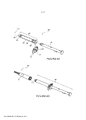
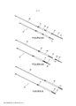
[0003] Milhões de seringas, como aquelas representadas na Figura 1 (2), são consumidas nos ambientes de cuidados de saúde todos os dias. Uma seringa típica (2) compreende um corpo tubular (4), um êmbolo (6) e uma agulha de injeção (8). Seringas típicas são fornecidas vazias e podem ser preenchidas a partir de um frasco de medicamento no momento do uso. A figura 2 ilustra o processo de preenchimento de uma seringa (2) com uma agulha (8) a partir de um frasco de medicamento líquido injetável (10). O medicamento pode ser líquido ou um pó misturado com um líquido no momento do uso. A figura 3 mostra a agulha (8), que é usada com seringas tradicionais (12). A agulha é conectada à seringa com uma parte central da agulha (19) e um adaptador luer lock (14) na frente da seringa.[0003] Millions of syringes, like those depicted in Figure 1(2), are consumed in healthcare settings every day. A typical syringe (2) comprises a tubular body (4), a plunger (6) and an injection needle (8). Typical syringes are supplied empty and can be filled from a medicine bottle at the time of use. Figure 2 illustrates the process of filling a syringe (2) with a needle (8) from a vial of injectable liquid medication (10). The medicine can be a liquid or a powder mixed with a liquid at the time of use. Figure 3 shows the needle (8), which is used with traditional syringes (12). The needle is connected to the syringe with a needle core (19) and a luer lock adapter (14) on the front of the syringe.
[0004] O uso de configurações de injeção da agulha acarreta o risco de uma agulha afiada entrar em contato ou perfurar uma estrutura que não é desejada. Por esse motivo, as denominadas “seringas de segurança” foram desenvolvidas. Uma configuração de seringa da segurança (20) é mostrada na figura 4, em que um membro protetor tubular (22) é acionado por uma mola para cobrir a agulha (8), quando liberado de uma posição de bloqueio em relação ao corpo da seringa (4).[0004] The use of needle injection configurations carries the risk of a sharp needle contacting or piercing an unwanted structure. For this reason, so-called “safety syringes” were developed. A safety syringe configuration (20) is shown in Figure 4, in which a tubular protective member (22) is spring loaded to cover the needle (8) when released from a locked position relative to the syringe body. (4).
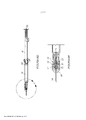
[0005] Essa configuração pode ser percebida de modo subaproveitado pelos usuários, como sendo volumosa e complicada de usar. Por exemplo, a proteção baseada em mola externa é relativamente grande, e pode ser rapidamente ativada, desse modo pulverizando partículas de sangue em direções indesejadas, tal como no usuário. Em alguns casos, é desejável encher previamente a seringa com o fármaco na fábrica para eliminar a etapa de enchimento mostrada na figura 2. Além disso, configurações existentes de seringa de segurança geralmente não são compatíveis com ser previamente preenchida com o fármaco. Fármacos comuns para injeção podem estar na forma líquida, ou podem compreender um pó misturado com um líquido no momento de uso. O elastômero e os materiais poliméricos de tal sistema podem carrear materiais, umidade ou oxigênio para o líquido contido dentro do corpo da seringa, ao longo do tempo. Corpos de seringa de vidro previamente preenchidos são mostrados na figura 5. A seringa previamente preenchida é construída com um corpo de vidro tubular (4) com um êmbolo (6) preso a um parador (5) e uma agulha permanentemente acoplada (8) ou uma conexão luer lock (14) para conexão de uma agulha no ponto de uso. O corpo de vidro é usado para minimizar qualquer carreamento de contaminantes, umidade ou oxigênio para dentro do fármaco. Estes corpos de seringa de vidro geralmente não são compatíveis com os sistemas de segurança de seringa atuais. Há uma necessidade por sistemas de injeção melhorados que abordam as desvantagens das configurações atualmente disponíveis.[0005] This configuration may be perceived as underused by users as being bulky and cumbersome to use. For example, the external spring-based guard is relatively large, and can be quickly activated, thereby spraying blood particles in unwanted directions, such as at the wearer. In some cases, it is desirable to pre-fill the syringe with drug at the factory to eliminate the filling step shown in Figure 2. Furthermore, existing safety syringe configurations are generally not compatible with being pre-filled with drug. Common drugs for injection may be in liquid form, or they may comprise a powder mixed with a liquid at the time of use. The elastomer and polymeric materials of such a system can carry materials, moisture or oxygen into the liquid contained within the syringe barrel over time. Pre-filled glass syringe bodies are shown in Figure 5. The pre-filled syringe is constructed of a tubular glass body (4) with a plunger (6) attached to a stopper (5) and a permanently attached needle (8) or a luer lock connection (14) for connecting a needle at the point of use. The glass body is used to minimize any entrainment of contaminants, moisture or oxygen into the drug. These glass syringe barrels are generally not compatible with current syringe safety systems. There is a need for improved injection systems that address the drawbacks of currently available configurations.
[0006] As figuras 1 a 5 ilustram vários aspectos das configurações de seringa de injeção convencionais.[0006] Figures 1 to 5 illustrate various aspects of conventional injection syringe configurations.
[0007] As figuras 6A a 6V ilustram vários aspectos de uma modalidade e um conjunto de seringa de segurança de acordo com a presente invenção, em que a agulha é automaticamente retraída após aplicar uma injeção.[0007] Figures 6A to 6V illustrate various aspects of an embodiment and a safety syringe assembly according to the present invention, in which the needle is automatically retracted after delivering an injection.
[0008] As figuras 7A a 7L ilustram vários aspectos de uma modalidade de um conjunto de seringa de segurança adaptável de acordo com a presente invenção, em que a agulha é manualmente retraída após aplicar uma injeção.[0008] Figures 7A to 7L illustrate various aspects of one embodiment of an adaptable safety syringe assembly in accordance with the present invention, wherein the needle is manually retracted after delivering an injection.
[0009] As figuras 8A a 8L ilustram vários aspectos de uma modalidade de um conjunto de seringa de segurança adaptável de acordo com a presente invenção, em que a agulha é automaticamente retraída após aplicar uma injeção.[0009] Figures 8A to 8L illustrate various aspects of one embodiment of an adaptable safety syringe assembly in accordance with the present invention, wherein the needle is automatically retracted after delivering an injection.
[0010] A figura 9 ilustra vários aspectos de uma modalidade de um processo para aplicar uma injeção usando uma configuração de seringa de segurança de retração automática de acordo com a presente invenção.[0010] Figure 9 illustrates various aspects of one embodiment of a process for delivering an injection using a self-retracting safety syringe configuration in accordance with the present invention.
[0011] A figura 10 ilustra vários aspectos de uma modalidade de um processo para aplicar uma injeção usando uma configuração de seringa de segurança de retração manual de acordo com a presente invenção.[0011] Figure 10 illustrates various aspects of one embodiment of a process for administering an injection using a manual retraction safety syringe configuration in accordance with the present invention.
[0012] A figura 11 ilustra outras possíveis aplicações para esta tecnologia, autoinjetores tipo caneta e seringas confortáveis.[0012] Figure 11 illustrates other possible applications for this technology, pen-type autoinjectors and comfortable syringes.
[0013] Uma modalidade é direcionada para um método de aplicar uma injeção, compreendendo: fornecer um conjunto de um êmbolo da seringa acoplado a um parador de seringa, dentro de um corpo de seringa que possa conter fluido para infusão. Um corpo de seringa tendo uma extremidade distal que é acoplada a um conjunto de agulha e uma extremidade proximal que pode ser acoplada a um cabo. Um êmbolo de seringa pode ser configurado para mover o parador da seringa no corpo da seringa para expelir o fluido para infusão para fora da agulha. Um conjunto de agulha pode ser construído a partir de uma agulha e de um alojamento para agulha. Uma agulha pode ser construída a partir de uma cânula, um canhão da cânula e um filamento. A agulha pode ser configurada para ser mantida no lugar pelo alojamento para agulha durante o processo de injeção. Em ou perto do término da injeção, a agulha pode ser configurada para se fixar ao parador da seringa, e o alojamento para agulha pode ser configurado para liberar a agulha, de modo que a agulha pode ser retraída para dentro do corpo da seringa. O êmbolo da seringa pode ser construído de um corpo de êmbolo, uma ponta do êmbolo, uma trava e um elemento de retração. O corpo do êmbolo da seringa pode ser configurado para cooperar com um componente de trava que retém um elemento de retratação, que pode ser configurado para retrair a agulha após o término da injeção. Ao retrair para dentro do corpo da seringa, o alojamento para agulha pode ser configurado para bloquear o buraco, de modo que a agulha não pode ser reexposta fora do corpo da seringa ou do alojamento para agulha.[0013] One embodiment is directed to a method of delivering an injection, comprising: providing a syringe plunger assembly coupled to a syringe stopper within a syringe barrel that can contain fluid for infusion. A syringe barrel having a distal end that attaches to a needle assembly and a proximal end that attachable to a handle. A syringe plunger may be configured to move the syringe stopper on the syringe barrel to expel the infusion fluid out of the needle. A needle assembly can be constructed from a needle and a needle housing. A needle can be constructed from a cannula, a cannula barrel and a filament. The needle can be configured to be held in place by the needle housing during the injection process. At or near the end of the injection, the needle can be configured to lock onto the syringe stopper, and the needle housing can be configured to release the needle so that the needle can be retracted into the syringe barrel. The syringe plunger may be constructed of a plunger body, a plunger tip, a lock and a retractor. The syringe plunger body may be configured to cooperate with a locking member which retains a retractor which may be configured to retract the needle upon completion of the injection. By retracting into the syringe body, the needle housing can be configured to block the hole so that the needle cannot be reexposed outside the syringe body or needle housing.
[0014] Outra modalidade é direcionada para um método de aplicar uma injeção, compreendendo: fornecer um conjunto de um êmbolo da seringa acoplado a um parador de seringa, dentro de um corpo de seringa que possa conter fluido para infusão. O corpo de seringa tendo uma extremidade distal que pode ser acoplada a um conjunto de agulha e uma extremidade proximal que pode ser acoplada a um cabo. O êmbolo de seringa pode ser configurado para mover o parador da seringa no corpo da seringa para expelir o fluido para infusão para fora da agulha. O conjunto de agulha pode ser construído a partir de uma agulha e de um alojamento para agulha. A agulha pode ser construída a partir de uma cânula, um canhão da cânula e um filamento. A agulha pode ser configurada para ser mantida no lugar pelo alojamento para agulha durante o processo de injeção. Em ou perto do término da injeção, a agulha pode ser configurada para se acoplar ao parador da seringa, e o alojamento para agulha pode ser configurada para liberar a agulha, de modo que a agulha pode ser retraída para dentro do corpo da seringa. O êmbolo da seringa pode ser configurado para permitir a retração manual da agulha dentro interior do corpo da seringa. Ao retrair para dentro do corpo da seringa, o alojamento para agulha pode ser configurado para bloquear o buraco, de modo que a agulha não pode ser novamente estendida para fora do corpo da seringa ou do alojamento para agulha.[0014] Another embodiment is directed to a method of administering an injection, comprising: providing a syringe plunger assembly coupled to a syringe stopper, within a syringe barrel that can contain fluid for infusion. The syringe body having a distal end that can be attached to a needle assembly and a proximal end that can be attached to a handle. The syringe plunger can be configured to move the syringe stopper on the syringe barrel to expel the infusion fluid out of the needle. The needle assembly may be constructed from a needle and a needle housing. The needle can be constructed from a cannula, a cannula barrel and a filament. The needle can be configured to be held in place by the needle housing during the injection process. At or near the end of the injection, the needle can be configured to engage the syringe stopper, and the needle housing can be configured to release the needle so that the needle can be retracted into the syringe barrel. The syringe plunger can be configured to allow manual retraction of the needle into the syringe barrel. By retracting into the syringe body, the needle housing can be configured to block the hole so that the needle cannot be extended back out of the syringe body or needle housing.
[0015] Outra modalidade é direcionada para um método de aplicar uma injeção, compreendendo: fornecer um conjunto de um êmbolo da seringa acoplado a um parador de seringa, dentro de um corpo de seringa que possa conter fluido para infusão. O corpo de seringa tendo uma extremidade distal que pode ser acoplada a um conjunto de agulha e uma extremidade proximal que pode ser acoplada a um cabo. O êmbolo de seringa pode ser configurado para mover ao parador da seringa no corpo da seringa para expelir o fluido para infusão para fora da agulha. O conjunto de agulha pode ser construído a partir de uma agulha e de um alojamento para agulha. A agulha pode ser construída a partir de uma cânula, um canhão da cânula e um filamento. A agulha pode ser configurada para ser mantida no lugar pelo alojamento para agulha durante o processo de injeção. Em ou perto do término da injeção, a agulha pode ser configurada para se acoplar ao parador da seringa, e o alojamento para agulha pode ser configurado para liberar a agulha, de modo que a agulha pode ser retraída para dentro do corpo da seringa. O êmbolo da seringa pode compreender uma haste do êmbolo, a ponta do êmbolo, o bloco do polegar, a base posterior, o retentor de travagem, a travagem e o elemento de retração. O êmbolo da seringa pode ser configurado para armazenar energia pelo carregamento de um elemento de retração durante o movimento anterógrado do êmbolo durante o movimento de injeção. O movimento retrógrado do êmbolo da seringa pode ser contido por um componente de travagem durante o processo de injeção. O componente de travagem pode ser configurado para liberar o êmbolo após o término da injeção, permitindo que a energia armazenada seja liberada, causando o movimento retrógrado do êmbolo e da agulha acoplada para retrair a agulha para dentro do corpo da seringa. Ao retrair para dentro do corpo da seringa, o alojamento para agulha pode ser configurado para bloquear o buraco, de modo que a agulha não pode ser novamente estendida para fora do corpo da seringa ou do alojamento para agulha.[0015] Another embodiment is directed to a method of administering an injection, comprising: providing a syringe plunger assembly coupled to a syringe stopper, within a syringe barrel that can contain fluid for infusion. The syringe body having a distal end that can be attached to a needle assembly and a proximal end that can be attached to a handle. The syringe plunger can be configured to move the syringe stopper on the syringe barrel to expel the infusion fluid out of the needle. The needle assembly may be constructed from a needle and a needle housing. The needle can be constructed from a cannula, a cannula barrel and a filament. The needle can be configured to be held in place by the needle housing during the injection process. At or near the end of the injection, the needle can be configured to engage the syringe stopper, and the needle housing can be configured to release the needle so that the needle can be retracted into the syringe barrel. The syringe plunger may comprise a plunger rod, plunger tip, thumb block, rear base, stop retainer, stop and retractor. The syringe plunger can be configured to store energy by loading a retractor during forward movement of the plunger during the injection stroke. The retrograde movement of the syringe plunger can be restrained by a braking component during the injection process. The locking member can be configured to release the plunger after completion of the injection, allowing stored energy to be released, causing retrograde movement of the plunger and attached needle to retract the needle into the syringe barrel. By retracting into the syringe body, the needle housing can be configured to block the hole so that the needle cannot be extended back out of the syringe body or needle housing.
[0016] Outra modalidade é direcionada para um sistema para injeção, compreendendo um corpo de seringa definindo uma câmara para medicamento interior ; um membro de parador configurado para ser inserido na câmara para medicamento interior para conter medicamento dentro da câmara de medicamento; um membro de êmbolo configurado para ser manipulado manualmente para inserir o membro parador em relação ao corpo da seringa; uma agulha com extremidades proximal e distal, com a extremidade proximal compreendendo uma geometria de ancoragem configurada para ser pelo menos parcialmente penetrada no membro parador, de modo que, após a retração do membro parador, a agulha é puxada proximalmente juntamente com o parador para estar pelo menos parcialmente contida dentro da câmara para medicamento interior ; e um membro de armazenamento de energia operacionalmente acoplado entre o membro parador e o corpo da seringa, com o membro de armazenamento da seringa sendo configurado para facilitar a retração do membro parador em relação ao corpo da seringa. O membro de êmbolo pode compreender um corpo de membro de êmbolo que define um volume interior, e em que o membro de armazenamento de energia é substancialmente alojado dentro do volume interior do corpo do membro de êmbolo. O sistema pode compreender ainda um membro de trava operacionalmente acoplado ao membro de êmbolo e alojado substancialmente dentro do volume interior do corpo do membro de êmbolo, com o membro de trava sendo configurado para ter um primeiro estado mecânico no qual o membro de trava mantém o membro de armazenamento de energia em um estado de armazenamento de energia, e um segundo estado mecânico no qual o membro de trava permite que o membro de armazenamento de energia libere a energia armazenada pelo membro de armazenamento de energia para auxiliar na retração do membro de parador em relação ao corpo da seringa. O membro de trava pode compreender uma porção de acionamento configurada para estender-se para fora do volume interior do corpo do membro de êmbolo e acoplar, operacionalmente, com o corpo da seringa, de modo que o membro de armazenamento de energia pode ser liberado automaticamente quando o membro de êmbolo e o membro parador interacoplado alcança uma posição insercional predeterminada em relação ao corpo da seringa. A posição insercional predeterminada pode ser uma em que o parador está posicionado em um estado de plena inserção em relação ao corpo da seringa. O membro de armazenamento de energia pode ser uma mola. A mola pode compreender um material selecionado do grupo consistindo em: aço inoxidável, aço-carbono, liga de cobre-berílio, liga de níquel-titânio, liga de cromo-silício e liga de cobalto-níquel. A mola pode compreender um polímero elastomérico. O polímero elastomérico pode ser selecionado do grupo consistindo em: um polímero estirênico, um polímero de copoliéster, poliuretano, poliamida, uma mistura de poliolefinas, uma liga de poliolefina, um plastômero de poliolefina, uma plastômero de poliolefina e borracha. O membro de armazenamento de energia pode compreender um membro de pélete (pellet) sólido. O membro de pélete sólido pode ser um polímero elastomérico selecionado do grupo consistindo em: um polímero estirênico, um polímero de copoliéster, poliuretano, poliamida, uma mistura de poliolefinas, uma liga de poliolefina, um plastômero de poliolefina, uma plastômero de poliolefina e borracha. A mola pode compreender uma única espiral geralmente em forma helicoidal. A mola pode compreender uma pluralidade de espirais geralmente em forma helicoidal. Pelo menos duas das espirais que compreendem a pluralidade de espirais geralmente em forma helicoidal podem ser coaxialmente alinhadas. Pelo menos duas das espirais que compreendem a pluralidade de espirais geralmente em forma helicoidal podem ser alinhadas longitudinalmente em paralelo. As espirais em forma helicoidal coaxialmente alinhadas também podem ser alinhadas longitudinalmente em paralelo. As espirais em forma helicoidal alinhadas coaxialmente e longitudinalmente em paralelo podem ser enroladas helicoidalmente com direções opostas de enrolamento entre si, para evitar a interferência da espiral após a compressão das espirais. A retração do êmbolo pode retrair o membro parador e a agulha interacoplados, de modo que pelo menos uma porção da agulha é retirada para dentro da câmara para medicamento interior do corpo da seringa. O membro de êmbolo pode ter uma ponta roscada e um recesso oco. O recesso êmbolo da ponta do êmbolo pode ser configurado para permitir que a extremidade proximal da agulha penetre totalmente no parador. O corpo da seringa pode compreender vidro. O corpo da seringa pode compreender um polímero. O membro parador pode compreender borracha butílica. A trava pode compreender um polímero selecionado do grupo consistindo em: polieterimida, peek e poliamida. O êmbolo pode compreender um polímero selecionado do grupo consistindo em: polieterimida, poliéter éter cetona (“peek”) e poliamida.[0016] Another embodiment is directed to a system for injection, comprising a syringe body defining an interior medicament chamber; a stopper member configured to be inserted into the inner medicament chamber to contain medicament within the medicament chamber; a plunger member configured to be manipulated manually to insert the stop member relative to the syringe body; a needle with proximal and distal ends, with the proximal end comprising an anchoring geometry configured to be at least partially penetrated into the stopper member, such that upon retraction of the stopper member, the needle is pulled proximally together with the stopper to be at least partially contained within the inner medicament chamber; and an energy storage member operatively coupled between the stop member and the syringe body, the syringe storage member being configured to facilitate retraction of the stop member with respect to the syringe body. The piston member may comprise a piston member body defining an interior volume, and wherein the energy storage member is housed substantially within the interior volume of the piston member body. The system may further comprise a latch member operatively coupled to the piston member and housed substantially within the interior volume of the piston member body, with the latch member being configured to have a first mechanical state in which the latch member maintains the energy storage member in an energy storage state, and a second mechanical state in which the latch member allows the energy storage member to release energy stored by the energy storage member to assist in the retraction of the stop member relative to the body of the syringe. The latch member may comprise an actuating portion configured to extend outside the interior volume of the plunger member body and operatively couple with the syringe body such that the energy storage member may be automatically released. when the plunger member and the intercoupled stop member reach a predetermined insertional position with respect to the syringe body. The predetermined insertional position may be one where the stopper is positioned in a fully inserted state with respect to the syringe barrel. The energy storage member can be a spring. The spring may comprise a material selected from the group consisting of: stainless steel, carbon steel, beryllium copper alloy, titanium nickel alloy, silicon chrome alloy and nickel cobalt alloy. The spring may comprise an elastomeric polymer. The elastomeric polymer may be selected from the group consisting of: a styrenic polymer, a copolyester polymer, polyurethane, polyamide, a polyolefin blend, a polyolefin alloy, a polyolefin plastomer, a polyolefin plastomer and rubber. The energy storage member may comprise a solid pellet member. The solid pellet member may be an elastomeric polymer selected from the group consisting of: a styrenic polymer, a copolyester polymer, polyurethane, polyamide, a blend of polyolefins, a polyolefin alloy, a polyolefin plastomer, a polyolefin plastomer and rubber . The spring may comprise a single spiral generally helical in shape. The spring may comprise a plurality of spirals generally in helical shape. At least two of the spirals comprising the plurality of generally helical shaped spirals may be coaxially aligned. At least two of the spirals comprising the plurality of generally helical shaped spirals may be longitudinally aligned in parallel. The coaxially aligned helical shaped spirals can also be longitudinally aligned in parallel. Helically shaped spirals aligned coaxially and longitudinally in parallel can be helically wound with opposite winding directions to each other, to avoid spiral interference after compression of spirals. Retraction of the plunger can retract the intercoupled stopper member and needle so that at least a portion of the needle is withdrawn into the interior medicament chamber of the syringe barrel. The plunger member may have a threaded end and a hollow recess. The plunger recess in the plunger tip can be configured to allow the proximal end of the needle to fully penetrate the stopper. The syringe body may comprise glass. The syringe barrel may comprise a polymer. The stop member may comprise butyl rubber. The lock may comprise a polymer selected from the group consisting of: polyetherimide, peek and polyamide. The plunger may comprise a polymer selected from the group consisting of: polyetherimide, polyether ether ketone ("peek") and polyamide.
[0017] Outra modalidade é direcionada para um sistema para injeção, compreendendo um corpo de seringa definindo uma câmara para medicamento interior; um membro parador definindo uma câmara para medicamento interior; um membro parador configurado para ser inserido na câmara para medicamento interior para conter medicamento dentro da câmara de medicamento; um membro de êmbolo configurado para ser manipulado manualmente para inserir o membro de parador em relação ao corpo da seringa; e uma agulha com extremidades proximal e distal, com a extremidade proximal compreendendo uma geometria de ancoragem configurada para ser pelo menos parcialmente inserida no membro parador, de modo que, após a retração do membro parador, a agulha é puxada proximalmente juntamente com o parador para estar pelo menos parcialmente contida dentro da câmara para medicamento interior ; em que o membro de parador é configurado para ser pelo menos parcialmente perfurado por uma extremidade afiada proximal da agulha, e em que a agulha tem pelo menos um elemento de ancoragem configurado para resistir à retirada posterior a ser parcialmente perfurado dentro do membro parador. O pelo menos um elemento de ancoragem pode ser formado a partir de um pedaço de material de estoque laminar. O pelo menos um elemento de ancoragem pode ser selecionado do grupo consistindo em: uma lasca, um corte de raspagem, uma geometria em gancho, e uma geometria em ponta de flecha. O parador pode ter uma geometria externa selecionada para combinar substancialmente uma geometria interna do corpo da seringa para vedar substancialmente com o corpo da seringa. Ao parador pode compreender um material elastomérico selecionado do grupo consistindo em: borracha clorobutílica, borracha bromobutílica e borracha de silicone. O sistema pode compreender ainda um revestimento vedante aplicado a pelo menos uma parte do parador para isolar os medicamentos do parador. O revestimento vedante pode compreender um filme de politetrafluoretileno (PTFE). O sistema pode compreender ainda uma camada lubrificante introduzida entre o parador e o corpo da seringa. A camada lubrificante pode compreender um óleo de silicone. Uma porção distal do membro de parador pode compreender um parador adaptável pronto para uso convencional. O membro de parador pode compreender um membro adaptável sólido não modificado sem recessos ou projeções para acoplamento com uma agulha. O membro de êmbolo pode ter uma ponta roscada e um recesso oco. O recesso êmbolo da ponta do êmbolo pode ser configurado para permitir que a extremidade proximal da agulha penetre totalmente no parador. O corpo da seringa pode compreender vidro. O corpo da seringa pode compreender um polímero. O material de estoque laminar pode compreender um metal selecionado do grupo consistindo em: aço inoxidável, liga de cobalto-cromo e titânio. A agulha pode definir uma passagem de fármaco por ela tendo uma entrada proximal localizada distalmente a uma extremidade distal do membro parador, quando a extremidade afiada proximal da agulha é penetrada dentro do membro parador.[0017] Another embodiment is directed to a system for injection, comprising a syringe body defining an interior medicament chamber; a stop member defining an interior medicament chamber; a stop member configured to be inserted into the inner medicament chamber to contain medicament within the medicament chamber; a plunger member configured to be manipulated manually to insert the stopper member relative to the syringe barrel; and a needle with proximal and distal ends, with the proximal end comprising an anchoring geometry configured to be at least partially inserted into the stopper member, such that upon retraction of the stopper member, the needle is pulled proximally along with the stopper to be at least partially contained within the inner medicament chamber; wherein the stopper member is configured to be at least partially pierced by a sharp proximal end of the needle, and wherein the needle has at least one anchor configured to resist withdrawal after being partially pierced within the stopper member. The at least one anchor may be formed from a piece of laminar stock material. The at least one anchoring element may be selected from the group consisting of: a flake, a scrape cut, a hook geometry, and an arrowhead geometry. The stopper may have an external geometry selected to substantially match an internal geometry of the syringe body to substantially seal with the syringe body. The stopper may comprise an elastomeric material selected from the group consisting of: chlorobutyl rubber, bromobutyl rubber and silicone rubber. The system may further comprise a sealant coating applied to at least a portion of the parador to isolate the medications from the parador. The sealant coating may comprise a polytetrafluoroethylene (PTFE) film. The system may further comprise a lubricating layer introduced between the stopper and the barrel of the syringe. The lubricating layer can comprise a silicone oil. A distal portion of the stopper member may comprise an adaptable stopper ready for conventional use. The stopper member may comprise an unmodified solid adaptable member without recesses or projections for engagement with a needle. The plunger member may have a threaded end and a hollow recess. The plunger recess in the plunger tip can be configured to allow the proximal end of the needle to fully penetrate the stopper. The syringe body may comprise glass. The syringe barrel may comprise a polymer. The laminar stock material may comprise a metal selected from the group consisting of: stainless steel, cobalt-chromium alloy and titanium. The needle may define a drug passage therethrough by having a proximal entry located distally to a distal end of the stopper member when the sharp proximal end of the needle is penetrated into the stopper member.
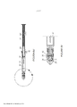
[0018] Referindo-se às figuras 6A a 6D, uma modalidade de seringa de segurança é representada, em que um corpo de seringa é montado em uma seringa de segurança completa, adicionando uma montagem de êmbolo, um flange e um conjunto de agulha. Referindo-se à figura 6A, um corpo de seringa (46) que compreende um cilindro (40), um adaptador luer lock (44); pode ser operacionalmente acoplado a um parador de seringa, ou membro parador (43) e é mostrado operacionalmente acoplado a um membro de êmbolo (41) inserido nele, que acopla o membro de parador (43). O membro de parador (43) pode compreender um material elastomérico, tal como borracha butílica, borracha clorobutílica, borracha bromobutílica e/ou borracha de silicone. Um revestimento de selante pode ser aplicado a pelo menos uma parte do membro parador (43) para isolar materiais medicamentosos do membro parador. O revestimento de selante pode, por exemplo, compreender um filme de PTFE. Uma camada lubrificante pode ser introduzida entre o parador e o corpo da seringa. A camada lubrificante pode compreender um óleo de silicone. Uma porção distal do membro parador pode compreender um parador adaptável pronto para uso convencional. O membro de parador pode compreender um membro adaptável sólido não modificado sem recessos ou projeções para acoplamento com uma agulha. Um flange (42) pode ser acoplado à extremidade proximal do cilindro (40). A porção distal do corpo de seringa (46) mostrado apresenta a forma de um adaptador luer lock (44) que pode ser seletivamente acoplado a um conjunto de agulha (45). A figura 6B mostra uma segunda vista isométrica dos itens mencionados na figura 6A. A figura 6C é uma ilustração da seringa e da montagem de êmbolo (48) que pode compreende um corpo de seringa (46), um flange (42) e uma montagem de êmbolo (41). A seringa e a montagem de êmbolo (48) são preferencialmente montadas pelo fabricante, mas também podem ser montados pelo usuário no ponto de cuidado. O corpo da seringa (46) pode compreender um cilindro (40), um adaptador luer lock (44) e pode ser configurado para se conectar por meio de interface com um membro de parador (43), que pode ser acoplado a um membro de êmbolo (41), como indicado acima. O cilindro (40) e o membro de parador (43) definem uma câmara para medicamento interior. No caso previamente preenchido, o fármaco (76) pode ser colocado dentro do cilindro (40) e estar contido pelo parador (43). O adaptador luer lock mostrado tem um furo (31) disposto através do mesmo, definindo um diâmetro interno para a passagem do fármaco (76) para fora do cilindro. Uma tampa (131) pode ser colocada na ponta do corpo da seringa para expedição, para ser removida antes de usar. O corpo da seringa pode compreender materiais tais como aqueles selecionados do grupo consistindo em: vidro, polímeros tais como COC, COP, náilon, polipropileno, polietileno ou metais.Ao parador da seringa preferencialmente compreende borracha butílica pouco lixiviável. No entanto, ao parador compreende também, ou alternativamente, materiais como borracha de silicone ou outro material elastomérico. Ao parador pode ser revestida com lubrificantes de grau farmacêutico, tais como óleo de silicone, PTFE ou outros lubrificantes de grau médico. Ao parador também pode ser coberta em um filme para proporcionar lubrificação e/ou uma barreira para contaminante de fármacos. É acoplado à parador da seringa demonstrada um êmbolo da seringa (41). Ao parador da seringa para conexão do êmbolo pode compreender, por exemplo, uma conexão de rosca, encaixe por pressão, conexão adesiva e/ou conexão soldada. O flange (42) compreende uma superfície de contato de trava (70) e um recurso de alinhamento (135). O recurso de alinhamento coopera com uma fenda no êmbolo (120, figura 6L) para alinhar os dois componentes. O recurso de alinhamento (135) também impede que o êmbolo seja retirado do corpo da seringa (46) quando ao flange (42) está instalada. A figura 6D ilustra uma seringa preenchida e uma montagem de êmbolo (48) com um conjunto de agulha (45) colocado dentro de uma tampa de agulha (47). A tampa de agulha pode ser configurada com nervuras (111) para alinhar a extremidade de filamento da agulha com a ID da ponta do adaptador luer lock (44) durante a instalação pelo usuário. Geometrias de alinhamento alternativas, tais como inchaços, múltiplos anéis anulares ou estruturas flexíveis, também poderiam ser usadas para o alinhamento. Alternativamente, a agulha (45) pode ser pré-acoplada à seringa e à montagem de êmbolo (48) pelo fabricante.[0018] Referring to figures 6A to 6D, an embodiment of a safety syringe is shown, in which a syringe body is assembled into a complete safety syringe, adding a plunger assembly, a flange and a needle assembly. Referring to Fig. 6A, a syringe body (46) comprising a barrel (40), a luer lock adapter (44); it may be operatively coupled to a syringe stopper, or stopper member (43) and is shown operatively coupled to a plunger member (41) inserted therein, which engages the stopper member (43). The stopper member (43) can comprise an elastomeric material such as butyl rubber, chlorobutyl rubber, bromobutyl rubber and/or silicone rubber. A sealant coating may be applied to at least a portion of the stopper member (43) to isolate medicated materials from the stopper member. The sealant coating can, for example, comprise a PTFE film. A lubricating layer can be introduced between the stopper and the barrel of the syringe. The lubricating layer can comprise a silicone oil. A distal portion of the stopper member may comprise an adaptable stopper ready for conventional use. The stopper member may comprise an unmodified solid adaptable member without recesses or projections for engagement with a needle. A flange (42) can be attached to the proximal end of the cylinder (40). The distal portion of the syringe barrel (46) shown is in the form of a luer lock adapter (44) that can be selectively coupled to a needle assembly (45). Figure 6B shows a second isometric view of the items mentioned in Figure 6A. Figure 6C is an illustration of the syringe and plunger assembly (48) which may comprise a syringe body (46), a flange (42) and a plunger assembly (41). The syringe and plunger assembly (48) are preferably assembled by the manufacturer, but can also be assembled by the user at the point of care. The syringe body (46) may comprise a barrel (40), a luer lock adapter (44) and may be configured to interface with a stop member (43), which may be coupled to a stop member (43). plunger (41) as indicated above. Cylinder (40) and stopper member (43) define an interior medicament chamber. In the pre-filled case, the drug (76) can be placed inside the cylinder (40) and be contained by the stopper (43). The luer lock adapter shown has a hole (31) disposed therethrough, defining an internal diameter for drug passage (76) out of the cylinder. A cap (131) can be placed on the end of the syringe barrel for shipping, to be removed before use. The syringe barrel may comprise materials such as those selected from the group consisting of: glass, polymers such as COC, COP, nylon, polypropylene, polyethylene or metals. The syringe stopper preferably comprises poorly leachable butyl rubber. However, the stopper also comprises, or alternatively, materials such as silicone rubber or other elastomeric material. The stopper can be coated with pharmaceutical grade lubricants such as silicone oil, PTFE or other medical grade lubricants. The stopper can also be covered in a film to provide lubrication and/or a barrier to drug contaminants. Attached to the syringe stopper shown is a syringe plunger (41). The syringe stopper for plunger connection may comprise, for example, a threaded connection, press fit, adhesive connection and/or soldered connection. The flange (42) comprises a latch contact surface (70) and an alignment feature (135). The alignment feature cooperates with a slot in the plunger (120, Figure 6L) to align the two components. The alignment feature (135) also prevents the plunger from being pulled out of the syringe body (46) when the flange (42) is installed. Figure 6D illustrates a pre-filled syringe and plunger assembly (48) with a needle assembly (45) placed within a needle cap (47). The needle cover can be configured with ribs (111) to align the thread end of the needle with the tip ID of the luer lock adapter (44) during user installation. Alternative alignment geometries such as bumps, multiple annular rings or flexible structures could also be used for alignment. Alternatively, the needle (45) can be pre-attached to the syringe and plunger assembly (48) by the manufacturer.
[0019] Referindo-se às figuras 6E a 6I, um conjunto de agulha (45) é acoplado dentro de uma tampa de agulha (47) para reter o conjunto de agulha dentro da tampa durante o transporte e ser liberada após a instalação do conjunto de agulha no adaptador luer lock da seringa. O conjunto de agulha para conexão com a tampa de agulha pode compreender, por exemplo, um ou mais dentre os seguintes: encaixe por pressão, conexão tipo baioneta, ajuste por pressão e/ou rosca. A tampa de agulha também pode ter uma borda (110), que pode ser usada para fixar uma barreira estéril para manter a esterilidade da agulha para expedição. Um componente espaçador também pode ser utilizado para reter a agulha (45) dentro da tampa de agulha (47) durante a expedição. A Figura 6F é uma vista explodida do conjunto de agulha (45) que é construído por um cone de nariz (49), trava de agulha (50), porta (51), vedação (52), base luer fêmea (53) e agulha (54). O cone de nariz (49) pode ser configurado para se encaixar na base luer fêmea (53) para conter os outros componentes. A trava da agulha (50) pode compreender braços flexíveis (75) que agarram a agulha (54) e podem ser flexionados para liberar a agulha. De preferência, os braços flexíveis (75) são configurados para agarrar a agulha (54) na incisura (61). No estado agarrado, a agulha (54) é colocada dentro do lúmen central do cone de nariz (49), da trava da agulha (50), da vedação (52) e da base luer fêmea (53). A porta (51) está preferencialmente alinhada de modo que o furo (72) esteja alinhado com o eixo central da agulha, e a porta esteja localizada dentro dos braços flexíveis (75) da trava da agulha. Os braços flexíveis (75) podem ser flexionados para liberar a agulha (54), aplicando uma força axial na agulha, forçando a porta para a frente e espalhando os braços flexíveis (75), permitindo que os braços liberem a agulha. Isso permite que a agulha seja retraída por um dos métodos mostrados neste documento. Uma vez que a agulha (54) é retraída e já não mais ocupa o furo na porta (72), a porta é forçada pelos braços flexíveis (75) lateralmente, desalinhando o furo (72) com o eixo da agulha, impedindo que a agulha avance novamente. A vedação (52) proporciona uma barreira ao escapamento de fármacos em torno da periferia da agulha (54). Esta vedação é mostrada como um O-anel elastomérico, mas outras vedações, como um septo, ou vedação de graxa de silicone compactada, pode ser usado. As figuras 6G a 6I são diferentes construções possíveis da agulha (54). Uma agulha (54) construída de uma cânula (55), canhão da cânula (56) e pelo menos um elemento de ancoragem ou filamento (57). O pelo menos um elemento de ancoragem (57) destina-se a penetrar e agarrar ao parador de borracha da seringa. O pelo menos um elemento de ancoragem (57) pode ter as projeções de junção do êmbolo (32), ou pode ser liso, e é geralmente configurado para resistir à posterior retirada para ser pelo menos parcialmente perfurado em pelo menos uma porção de um membro de parador. O elemento de ancoragem (57) pode ser formado a partir de um pedaço de material de estoque laminar, como de um metal selecionado a partir do grupo que consiste em aço inoxidável, liga de cobalto-cromo e titânio, e pode definir uma geometria, como um filamento, um corte de apara, uma geometria de gancho e/ou uma geometria ponta de seta. Em uma modalidade, esses componentes compreendem um metal como aço inoxidável ou titânio; em outra modalidade, eles também podem compreender polímero ou vidro. A cânula demonstrada (55) é ligada à parte central da cânula (56) tal como usando um ou mais dos seguintes: adesivo, epóxi, solda, brasagem, soldadura, soldadura a laser, solda por fricção, encaixe por pressão ou estampo mecânico. Em outra modalidade, a agulha (54) pode ser fabricada como uma estrutura de peça única. Referindo-se à figura 6, o filamento ou o elemento de ancoragem (57) pode ser construído com uma trava (112), que se acopla a uma fenda (60) para reter o filamento. Uma passagem de fluido (77) é mantida ao redor do filamento na configuração mostrada, de modo que o fluido de injeção não é obstruído. A fenda (60) também serve para expulsar bolhas de ar do corpo da seringa antes de aplicar a injeção. Referindo-se à figura 6H, o filamento (57) é construído com uma estrutura flexível (113) que permite um encaixe por pressão na ID do canhão da cânula (114) para reter o filamento. Adesivo também pode ser colocado na estrutura flexível (113) para reter o filamento dentro do canhão da cânula (56). As passagens de fluido (77) e (78) são mantidas ao redor do filamento, de modo que o fluido de injeção não é obstruído. Referindo-se à modalidade da figura 6I, o filamento (115) pode ser construído integral com o canhão da cânula (58). Uma passagem de fluido (79) é mantida ao redor ou através do filamento, de modo que o fluido de injeção não é obstruído. Uma incisura (61) é formada no canhão da cânula (58) para se acoplar com o conjunto de agulha e fixar no local a agulha (54) durante a injeção. Esta incisura também pode ser construída fixando um anel ao redor da cânula, tal como utilizando adesivo, encaixe por pressão ou técnicas de soldagem. Alternativamente, outros métodos de fixação de agulha no parador podem ser utilizados, tais como: ligação por sucção entre a parte central da cânula e o parador, ou uma agulha desencapada que é afiada em ambas as extremidades sem barbelas. Os tamanhos do diâmetro da cânula variam de cerca de 0,00725 polegada (calibre 34) até cerca de 0,072 polegada (calibre 15) de diâmetro externo. Os tamanhos do comprimento da cânula variam de cerca de M de polegada até cerca de 2,0 polegadas de comprimento, projetando-se para fora do dispositivo para injeção no paciente. O canhão da cânula (56) pode ser dimensionado de modo que o diâmetro externo seja menor do que o diâmetro interior (31, figura 6C) do adaptador luer lock (44, figura 6C), de modo a deslizar livremente dentro do diâmetro interno da ponta luer lock da seringa. Os corpos de seringa comercialmente disponíveis têm uma ponta luer lock com diâmetro interno que mede de cerca 0,040” a cerca de 0,080”. O diâmetro externo da parte central da cânula (56) pode variar de cerca de 0,020” até cerca de 0,079”. Preferencialmente, a parte central da cânula possui cerca de 0,039” de diâmetro externo. Nas várias modalidades retratadas nas figuras 6H a 6I, por exemplo, a agulha pode definir uma passagem de fármaco por ela que tem uma entrada proximal que está distal a uma extremidade distal do membro de parador quando a extremidade proximal afiada (ou seja, barbada, etc.) do conjunto de agulha penetra no membro de parador.[0019] Referring to figures 6E to 6I, a needle assembly (45) is coupled inside a needle cover (47) to retain the needle assembly inside the cover during transportation and be released after installing the set needle into the syringe luer lock adapter. The needle assembly for connection to the needle cap may comprise, for example, one or more of the following: press fit, bayonet connection, press fit and/or thread. The needle cover may also have a lip (110) which may be used to attach a sterile barrier to maintain the sterility of the needle for shipping. A spacer member can also be used to retain the needle (45) within the needle cover (47) during shipment. Figure 6F is an exploded view of the needle assembly (45) which is constructed of a nose cone (49), needle lock (50), port (51), seal (52), female luer base (53) and needle (54). The nose cone (49) can be configured to mate with the female luer base (53) to contain the other components. The needle lock (50) may comprise flexible arms (75) which grip the needle (54) and can be flexed to release the needle. Preferably, the flexible arms (75) are configured to grip the needle (54) in the notch (61). In the gripped state, the needle (54) is placed within the central lumen of the nose cone (49), the needle lock (50), the seal (52) and the female luer base (53). The port (51) is preferably aligned so that the hole (72) is aligned with the central axis of the needle, and the port is located within the flexible arms (75) of the needle lock. The flexible arms (75) can be flexed to release the needle (54) by applying an axial force on the needle, forcing the port forward and spreading the flexible arms (75), allowing the arms to release the needle. This allows the needle to be retracted by one of the methods shown in this document. Once the needle (54) is retracted and no longer occupies the hole in the port (72), the port is forced laterally by the flexible arms (75), misaligning the hole (72) with the needle axis, preventing the needle advance again. The seal (52) provides a barrier to drug leakage around the periphery of the needle (54). This seal is shown as an elastomeric O-ring, but other seals, such as a septum, or compacted silicone grease seal, can be used. Figures 6G to 6I are different possible constructions of the needle (54). A needle (54) constructed of a cannula (55), cannula hub (56) and at least one anchor or filament (57). The at least one anchor (57) is intended to penetrate and grip the rubber stopper of the syringe. The at least one anchor member (57) may have plunger joining projections (32), or may be smooth, and is generally configured to resist further withdrawal to be at least partially pierced in at least a portion of a member. of parador. The anchor (57) may be formed from a piece of laminar stock material, such as a metal selected from the group consisting of stainless steel, cobalt-chromium alloy and titanium, and may define a geometry, as a filament, a trim cut, a hook geometry, and/or an arrowhead geometry. In one embodiment, these components comprise a metal such as stainless steel or titanium; in another embodiment, they may also comprise polymer or glass. The demonstrated cannula (55) is attached to the central part of the cannula (56) such as using one or more of the following: adhesive, epoxy, solder, solder, solder, laser solder, friction weld, press fit or mechanical stamping. In another embodiment, the needle (54) can be manufactured as a one-piece structure. Referring to figure 6, the filament or anchoring element (57) can be constructed with a latch (112), which engages in a slot (60) to retain the filament. A fluid passage (77) is maintained around the filament in the configuration shown, so that the injection fluid is not obstructed. The slit (60) also serves to expel air bubbles from the body of the syringe before administering the injection. Referring to Fig. 6H, the filament (57) is constructed with a flexible frame (113) that allows for a press fit to the cannula barrel ID (114) to retain the filament. Adhesive may also be placed on the flexible frame (113) to retain the filament within the cannula barrel (56). Fluid passages (77) and (78) are maintained around the filament so that injection fluid is not obstructed. Referring to the embodiment of figure 6I, the filament (115) can be built integral with the cannula barrel (58). A fluid passage (79) is maintained around or through the filament so that the injection fluid is not obstructed. A notch (61) is formed in the cannula barrel (58) to mate with the needle assembly and secure the needle (54) in place during injection. This notch can also be constructed by attaching a ring around the cannula, such as using adhesive, press fit or welding techniques. Alternatively, other methods of attaching the needle to the stopper can be used, such as: suction connection between the central part of the cannula and the stopper, or a bare needle that is sharpened at both ends without barbs. Cannula diameter sizes range from about 0.00725 inch (34 gauge) to about 0.072 inch (15 gauge) outside diameter. Cannula length sizes range from about 1/2 inch to about 2.0 inches in length, projecting out of the device for injection into the patient. The cannula barrel (56) can be sized so that the outer diameter is smaller than the inner diameter (31, Figure 6C) of the luer lock adapter (44, Figure 6C), so as to slide freely within the inner diameter of the cannula. syringe luer lock tip. Commercially available syringe barrels have a luer lock tip with an inside diameter measuring from about 0.040” to about 0.080”. The outside diameter of the central portion of the cannula (56) can range from about 0.020” to about 0.079”. Preferably, the center portion of the cannula is about 0.039” outside diameter. In the various embodiments depicted in Figures 6H to 6I, for example, the needle may define a drug passage through it that has a proximal port that is distal to a distal end of the stopper limb when the sharpened proximal end (i.e., barbed, etc.) of the needle assembly penetrates the stopper member.
[0020] Referindo-se às figuras 6J a 6L, uma montagem de êmbolo (41) pode compreender uma base do êmbolo ou corpo do membro de êmbolo (62), um membro de trava (64), elemento de retração ou membro de armazenamento de energia (63) e a ponta do êmbolo (65). A figura 6J é uma vista explodida do êmbolo (41). A base do êmbolo (62) é uma estrutura tubular oca com uma superfície de acoplamento de trava (67) localizada próxima do elemento de bloco do polegar (66). A montagem de êmbolo (41) pode ter uma ponta distal roscada para acoplar em um membro de parador, e pode compreender um recesso oco configurado para permitir que a extremidade proximal do membro da agulha penetre totalmente em um membro de parador. O bloco do polegar (66) fecha uma extremidade da estrutura tubular, criando um local para um elemento de retração (63) ser retido. É colocado dentro do corpo do membro de êmbolo (62) um membro de trava (64), que retém o elemento de retração ou o membro de armazenamento de energia (63). O corpo do membro de êmbolo (62) pode definir um volume interior configurado de modo que um membro de armazenamento de energia ou elemento de retração (63) possa ser alojado substancialmente dentro do volume interior do corpo do membro de êmbolo. Com um membro de armazenamento de energia tipo mola, o membro de mola pode compreender uma única espiral em forma geralmente helicoidal. Em outra modalidade, o membro de mola pode compreender uma pluralidade de espirais geralmente em forma helicoidal, que podem, por exemplo, ser coaxialmente alinhadas, alinhadas longitudinalmente em paralelo ou tanto coaxialmente alinhadas como alinhadas longitudinalmente em paralelo. Em uma modalidade em que o membro de mola compreende elementos de mola ou espirais tanto coaxialmente alinhados como longitudinalmente paralelos alinhados, os elementos de mola ou molas podem ser helicoidalmente enrolados com direções opostas de enrolamento em relação uns aos outros, para evitar a interferência da espiral após a compressão das espirais.[0020] Referring to figures 6J to 6L, a piston assembly (41) may comprise a piston base or piston member body (62), a lock member (64), retraction member or storage member power supply (63) and the plunger tip (65). Figure 6J is an exploded view of the plunger (41). The base of the plunger (62) is a hollow tubular structure with a latch engagement surface (67) located close to the thumb block member (66). The plunger assembly (41) may have a threaded distal end for engaging a stopper member, and may comprise a hollow recess configured to allow the proximal end of the needle member to fully penetrate a stopper member. The thumb block (66) closes off one end of the tubular frame, creating a place for a retractor (63) to be retained. Placed within the body of the piston member (62) is a latch member (64) which retains the retractor or energy storage member (63). The piston member body (62) may define an interior volume configured such that an energy storage member or retractor member (63) can be housed substantially within the interior volume of the piston member body. With a spring-like energy storage member, the spring member may comprise a single spiral in a generally helical shape. In another embodiment, the spring member may comprise a plurality of spirals generally in helical shape, which may, for example, be coaxially aligned, longitudinally aligned parallel or both coaxially aligned and longitudinally aligned parallel. In one embodiment where the spring member comprises both coaxially aligned and longitudinally parallel aligned spring elements or spirals, the spring elements or springs may be helically wound with opposite directions of winding relative to each other to avoid spiral interference. after compression of the spirals.
[0021] Distalmente à superfície de acoplamento de trava (67) está uma fenda de limpeza (120), a qual permite que o membro de trava (64) se desloque em direção à rosca do êmbolo (65), após a liberação do elemento de retração (63). A rosca do êmbolo (65) é acoplada à ponta da base do êmbolo (62) com uma conexão por encaixe entre as abas (121) e ranhuras (123). Outros métodos de fixação da rosca do êmbolo (65) à base do êmbolo (62) incluem, mas se limitam, a: uma conexão roscada, uma conexão ligada, uma conexão soldada e/ou uma estrutura integral. Um protetor de trava (122) pode ser configurado para proteger a trava de ser ativada inadvertidamente. O membro de trava demonstrado (64) tem um gancho de trava (68), um elemento de gatilho (69) e um recurso de junção do elemento de retração (124). O membro da trava pode compreender um material polimérico, tal como uma polieterimida, peek e/ou poliamida. Da mesma forma, os vários componentes do êmbolo podem compreender um material polimérico, como uma polieterimida, peek e/ou poliamida. A figura 6K mostra uma vista montada do êmbolo (41). A figura 6L ilustra uma vista em seção transversal do êmbolo (41) mostrando o membro de trava (64) instalado no local para reter o elemento de retração ou o membro de armazenamento de energia (63) em uma condição comprimida antes da retração de uma agulha. A trava possui um gancho (68) que se acopla a uma superfície de acoplamento (67) dentro do corpo do êmbolo (62) para reter o elemento de retração dentro do êmbolo em um estado compactado. Uma configuração alternativa pode ter o elemento de retração (63) do lado de fora da haste do êmbolo. O membro de trava demonstrado (64) tem um elemento de gatilho (69) que atua para desacoplar o gancho (68) da superfície de acoplamento (67), liberando o elemento de retração (63) para expandir. A trava é acionada para liberar quando uma força axial é aplicada no gatilho (69). Essa força axial é aplicada na parte inferior do movimento de injeção pelo contato com a superfície de contato do flange (70, figura 6S). O elemento de retração liberado força a trava para se mover axialmente ao longo da fenda (120) na base do êmbolo (62), com este movimento sendo reagido pela superfície de contato da trava (70) do flange (42) mostrado na figura 6M, forçando o êmbolo a se mover regressivamente, retraindo a agulha (54, figura 6F) que é acoplada à parador (43), que é acoplada à rosca do êmbolo que é acoplado ao êmbolo. O elemento de retração mostrado aqui é uma mola de metal, mas outros elementos compressíveis são previstos. O membro de armazenamento de energia, ou o elemento de retração (63), pode compreender uma ou mais molas helicoidais, ou um membro de pélete sólido, e pode compreender materiais como um material polimérico, elastomérico ou de borracha. Por exemplo, uma mola do membro de armazenamento de energia pode compreender um material selecionado do grupo consistindo em: aço inoxidável, aço-carbono, liga de cobre-berílio, liga de níquel-titânio, liga de cromo-silício e liga de cobalto- níquel. Alternativamente, uma mola do membro de armazenamento de energia pode compreender um polímero elastomérico, como um material selecionado do grupo consistindo em: um polímero estirênico, um polímero de copoliéster, poliuretano, poliamida, uma mistura de poliolefinas, uma liga de poliolefina, um plastômero de poliolefina, uma plastômero de poliolefina e borracha. Um membro de armazenamento de energia de pélete sólido pode compreender um polímero elastomérico selecionado do grupo consistindo em: um polímero estirênico, um polímero de copoliéster, poliuretano, poliamida, uma mistura de poliolefinas, uma liga de poliolefina, um plastômero de poliolefina, uma plastômero de poliolefina e borracha. A base do êmbolo (62), a trava (64) e a ponta do êmbolo (65) podem ser construídos a partir de um polímero, tal como náilon, Ultem, polieteretercetona, polietileno, polipropileno, COC, COP, vidro ou polímeros preenchidos com fibra de carbono, ou outros compostos poliméricos preenchidos. Materiais alternativos para a trava, a base do êmbolo ou a ponta do êmbolo são metais ou outros materiais estruturais.[0021] Distal to the lock coupling surface (67) is a cleaning slit (120), which allows the lock member (64) to move towards the plunger thread (65) after releasing the element of retraction (63). The plunger thread (65) is coupled to the tip of the plunger base (62) with a push-fit connection between the tabs (121) and grooves (123). Other methods of attaching the piston thread (65) to the piston base (62) include, but are limited to: a threaded connection, a bonded connection, a welded connection, and/or an integral frame. A lock guard (122) may be configured to protect the lock from being inadvertently activated. The demonstrated latch member (64) has a latch hook (68), a trigger member (69) and a retraction member joint feature (124). The latch member may comprise a polymeric material, such as a polyetherimide, peek and/or polyamide. Likewise, the various components of the plunger may comprise a polymeric material such as a polyetherimide, peek and/or polyamide. Figure 6K shows an assembled view of the plunger (41). Figure 6L illustrates a cross-sectional view of the plunger (41) showing the latch member (64) installed in place to retain the retractor or energy storage member (63) in a compressed condition prior to retraction of a needle. The latch has a hook (68) that engages a mating surface (67) within the piston body (62) to retain the retractor within the piston in a compressed state. An alternative configuration may have the retractor (63) on the outside of the piston rod. The demonstrated latch member (64) has a trigger element (69) which acts to disengage the hook (68) from the mating surface (67), freeing the retraction element (63) to expand. The latch is actuated to release when an axial force is applied to the trigger (69). This axial force is applied at the bottom of the injection stroke by contacting the flange contact surface (70, figure 6S). The released retractor forces the latch to move axially along the slot (120) in the base of the plunger (62), with this movement being reacted by the latch contact surface (70) of the flange (42) shown in Figure 6M , forcing the plunger to move backwards, retracting the needle (54, figure 6F) which is coupled to the stopper (43), which is coupled to the thread of the plunger which is coupled to the plunger. The retractor shown here is a metal spring, but other compressible elements are provided. The energy storage member, or retraction member (63), may comprise one or more coil springs, or a solid pellet member, and may comprise materials such as a polymeric, elastomeric or rubber material. For example, a spring of the energy storage member may comprise a material selected from the group consisting of: stainless steel, carbon steel, beryllium copper alloy, nickel titanium alloy, silicon chrome alloy, and cobalt-cobalt alloy. nickel. Alternatively, a spring of the energy storage member may comprise an elastomeric polymer, such as a material selected from the group consisting of: a styrenic polymer, a copolyester polymer, polyurethane, polyamide, a polyolefin blend, a polyolefin alloy, a plastomer of polyolefin, a polyolefin and rubber plastomer. A solid pellet energy storage member may comprise an elastomeric polymer selected from the group consisting of: a styrenic polymer, a copolyester polymer, polyurethane, polyamide, a blend of polyolefins, a polyolefin alloy, a polyolefin plastomer, a plastomer polyolefin and rubber. The plunger base (62), lock (64) and plunger tip (65) may be constructed from a polymer such as nylon, Ultem, polyetheretherketone, polyethylene, polypropylene, COC, COP, glass or filled polymers with carbon fiber, or other filled polymeric composites. Alternative materials for the latch, plunger base or plunger tip are metals or other structural materials.
[0022] Referindo-se às figuras 6M a 6V, uma sequência de injeção para uma modalidade é ilustrada. A figura 6 M é uma vista lateral mostrando o conjunto do corpo da seringa (48) com o corpo da seringa (46), o flange (42) e o êmbolo (41) instalados. A tampa da agulha (47) guia a agulha (45) para dentro da ponta da seringa. A figura 6N mostra uma seção transversal do dispositivo durante o uso. A agulha (45) está acoplada ao conjunto do corpo da seringa (48). O fármaco a ser administrado (76) foi pré-carregado dentro do cilindro de seringa (40) antes da montagem da seringa. O conjunto de agulha (45) está agarrando a agulha (54) com a trava da agulha (50) e a porta (51) alinhadas para reter a agulha durante o transporte, manuseio, montagem, injeção e/ou retirada do paciente. O parador da seringa (43) está localizada na extremidade do êmbolo (41) e é capaz de ser retraída pela distância (74) caso a aspiração da agulha seja necessária para identificar se o local de injeção está em um vaso sanguíneo. O elemento de retração (63) é contido pela trava (64) em um estado comprimido. A pessoa que administra a injeção aplica uma força axial no bloco do polegar do êmbolo (66) e o flange (42) para forçar o líquido através da agulha e para dentro do paciente. A figura 60 mostra uma seção transversal do dispositivo ilustrando a aspiração da agulha. Uma força pode ser aplicada ao bloco do polegar (66) para puxar o êmbolo (41) e regredir ao parador (43), reduzindo a distância (74) e criando um leve vácuo na ponta da agulha, aspirando a agulha. A figura 6P ilustra a agulha sendo agarrada pela trava da agulha (50) através dos braços flexíveis (75) que interfaceiam com os entalhes (61) na parte central da cânula. A figura 6Q ilustra a progressão de aplicar a injeção. Uma força pode ser aplicada anterógradas ao bloco do polegar (66) movendo o êmbolo (41) e o parador (43) para expulsar o fármaco (76) através da agulha. A figura 6R mostra a agulha sendo retida durante a injeção. A Figura 6S ilustra o término da injeção. O êmbolo (41) foi totalmente avançado. A agulha é liberada, forçando a porta (51) para dentro dos braços de trava da agulha (75), espalhando os braços e liberando a agulha (54) para a retração. Ao parador (43) foi perfurada pelo filamento (57). O filamento (57) está configurado para se acoplar com o parador após este ser perfurado, permitindo a retração da agulha por meio do movimento retrógrado do parador (43). A trava (64) é girada pelo contato entre uma superfície de contato da trava (70) que se projeta do flange (42) e do elemento de gatilho da trava (69). O gancho da trava (68) se desacopla da superfície de acoplamento (67), liberando o elemento de retração (63) para aplicar uma força axial para mover o êmbolo (41) e regredir ao parador (43), retraindo a agulha acoplada (54) da ponta da seringa. O desacoplamento do gancho da trava pode ocorrer simultaneamente com o fim do movimento de injeção, ou pode ocorrer antes do final do movimento de injeção. O usuário pode, então, retirar o polegar do bloco do polegar (66) para permitir que o êmbolo se movera regressivamente, retraindo a agulha. Alternativamente, o usuário pode manter o contato do polegar com o bloco do polegar (66) para controlar a velocidade de retração. A figura 6T ilustra uma modalidade de um mecanismo de liberação de agulha. O filamento (57) da agulha (57) entra em contato e se acopla com o parador (43), que é acoplado com o êmbolo (41). O acoplamento do filamento (57) com o parador (53) pode ser criado perfurando o filamento dentro do parador. Outros métodos adequados para acoplar o filamento no parador incluem, mas não se limitam, a: conexão por vácuo, adesivo, gancho e/ou velcro. A agulha (54) é forçada em direção ao parador (43) durante a ação de acoplamento e entra em contato com a porta (51) com a extremidade distal da parte central da cânula (56) e empurra a porta para dentro do encaixe com os braços flexíveis (75) da trava da agulha (51). Os braços flexíveis são expandidos lateralmente, permitindo que a incisura (61) da agulha (54) se mova axialmente mediante a retração da agulha (54) pelo elemento de retração (63) acoplado com o êmbolo (41) e acoplado com o parador (43). A figura 6U ilustra a agulha retraída (54) dentro do cilindro (40). O elemento de retração (63) forçou o êmbolo (41) para trás, o qual retrai a agulha (57) que está acoplada ao parador (43) e ao êmbolo (41). A taxa de retração dessa agulha é amortecida pelo atrito entre o parador (43) e o cilindro (40). Diferentes níveis de lubrificação do parador (43) podem ser usados para permitir uma retração rápida ou lenta da agulha. A figura 6V ilustra a posição da porta (51) uma vez que a agulha está retraída. Os braços flexíveis (75) forçam o furo da porta (72, figura 6F) a se desalinhar com o eixo da agulha, evitando a reexposição da agulha pelo usuário. Um elemento de agarramento de agulha (71) agora está alinhado com o eixo da agulha, impedindo que a mesma seja reexposta pelo avanço acidental do êmbolo.[0022] Referring to figures 6M to 6V, an injection sequence for one embodiment is illustrated. Figure 6M is a side view showing the syringe body (48) assembly with the syringe body (46), flange (42) and plunger (41) installed. The needle cap (47) guides the needle (45) into the tip of the syringe. Figure 6N shows a cross-section of the device during use. The needle (45) is coupled to the syringe body assembly (48). The drug to be administered (76) was preloaded into the syringe barrel (40) prior to syringe assembly. The needle assembly (45) is gripping the needle (54) with the needle lock (50) and port (51) aligned to retain the needle during transport, handling, assembly, injection and/or patient withdrawal. The syringe stopper (43) is located at the end of the plunger (41) and is capable of being retracted through the distance (74) should needle aspiration be required to identify whether the injection site is in a blood vessel. The retraction member (63) is held by the latch (64) in a compressed state. The person administering the injection applies an axial force to the plunger thumb block (66) and flange (42) to force liquid through the needle and into the patient. Figure 60 shows a cross-section of the device illustrating needle aspiration. Force can be applied to the thumb block (66) to pull the plunger (41) back to the stopper (43), reducing the distance (74) and creating a slight vacuum at the needle tip, aspirating the needle. Figure 6P illustrates the needle being gripped by the needle lock (50) through the flexible arms (75) that interface with the notches (61) in the central part of the cannula. Figure 6Q illustrates the progression of giving the injection. Force can be applied anterograde to the thumb block (66) by moving the plunger (41) and stopper (43) to expel the drug (76) through the needle. Figure 6R shows the needle being retained during the injection. Figure 6S illustrates the completion of the injection. The plunger (41) has been fully advanced. The needle is released, forcing the port (51) into the needle lock arms (75), spreading the arms and releasing the needle (54) for retraction. The stopper (43) was perforated by the filament (57). The filament (57) is configured to engage with the stopper after it is pierced, allowing the needle to be retracted through the retrograde movement of the stopper (43). The latch (64) is rotated by contact between a latch contact surface (70) projecting from the flange (42) and the latch trigger element (69). The latch hook (68) disengages from the coupling surface (67), releasing the retraction member (63) to apply an axial force to move the plunger (41) and return to the stopper (43), retracting the coupled needle ( 54) from the tip of the syringe. The disengagement of the latch hook can occur simultaneously with the end of the injection movement, or it can occur before the end of the injection movement. The user can then withdraw the thumb from the thumb block (66) to allow the plunger to move backwards, retracting the needle. Alternatively, the user can maintain thumb contact with the thumb block (66) to control the retraction speed. Figure 6T illustrates one embodiment of a needle release mechanism. The filament (57) of the needle (57) contacts and engages with the stopper (43), which is coupled with the plunger (41). Coupling the filament (57) with the stopper (53) can be created by piercing the filament inside the stopper. Other suitable methods of attaching the filament to the stopper include, but are not limited to: vacuum connection, adhesive, hook and/or velcro. The needle (54) is forced towards the stopper (43) during the coupling action and contacts the port (51) with the distal end of the central part of the cannula (56) and pushes the port into the socket with the flexible arms (75) of the needle lock (51). The flexible arms are laterally expanded, allowing the notch (61) of the needle (54) to move axially upon retraction of the needle (54) by the retraction element (63) coupled with the plunger (41) and coupled with the stopper ( 43). Figure 6U illustrates the retracted needle (54) within the cylinder (40). The retraction element (63) has forced the plunger (41) backwards, which retracts the needle (57) which is coupled to the stopper (43) and the plunger (41). The rate of retraction of that needle is damped by friction between the stopper (43) and the cylinder (40). Different levels of lubrication of the stopper (43) can be used to allow a fast or slow retraction of the needle. Figure 6V illustrates the position of port (51) once the needle is retracted. The flexible arms (75) force the hole in the port (72, figure 6F) to misalign with the needle shaft, preventing the user from re-exposing the needle. A needle gripper (71) is now aligned with the needle shaft, preventing the needle from being re-exposed by accidental advancement of the plunger.
[0023] Referindo-se às figuras 7A a LD, uma modalidade de seringa de segurança é representada, em seringa de segurança manualmente ativada. A figura 7A é uma ilustração de uma montagem de seringa e êmbolo (140) que pode compreender um corpo de seringa (46) conectado a um flange (81) e um membro de êmbolo (80). O corpo da seringa pode ser fornecido vazio ou preenchido com fármaco antes da montagem. Uma agulha (45) é mostrada colocada dentro de uma tampa de agulha (47). Na modalidade mostrada, a agulha é para ser acoplada ao corpo da seringa (46) usando a ponta luer lock (44) acoplada ao cilindro (40). Alternativamente, o flange (81) e o membro de êmbolo (80) podem ser fornecidos juntamente com o corpo da seringa (46) e montados pelo usuário no ponto de cuidado. Da mesma forma, a agulha (45) pode ser pré-acoplada à montagem de seringa e êmbolo (140) pelo fabricante. A figura 7B é uma ilustração da seringa de segurança montada e pronta para iniciar a injeção. A agulha mostrada (45) é acoplada ao corpo da seringa (46), com o flange (81) e membro do êmbolo (80) acoplados. A figura 7C é uma vista explodida do dispositivo. O corpo da seringa (46) compreende um cilindro (40), uma ponta luer lock (44) e está configurado para ser interfaceado com um membro parador (43). O fármaco (76) pode ser previamente preenchido dentro do cilindro e mantida com o parador (43). Alternativamente, o fármaco pode ser preenchido na seringa no momento de uso de um frasco de medicamento. O membro de êmbolo (80) é rosqueado no parador (43). Os cabos (81) são acoplados ao corpo da seringa (46). A agulha (45) dentro da tampa de agulha (47) é, em seguida, acoplada ao corpo da seringa (46).[0023] Referring to figures 7A to LD, a safety syringe modality is represented, in a manually activated safety syringe. Figure 7A is an illustration of a syringe and plunger assembly (140) which may comprise a syringe body (46) connected to a flange (81) and a plunger member (80). The syringe barrel can be shipped empty or filled with drug prior to assembly. A needle (45) is shown placed inside a needle cap (47). In the embodiment shown, the needle is to be coupled to the syringe body (46) using the luer lock tip (44) coupled to the barrel (40). Alternatively, the flange (81) and plunger member (80) can be supplied along with the syringe body (46) and assembled by the user at the point of care. Likewise, the needle (45) may be pre-attached to the syringe and plunger assembly (140) by the manufacturer. Figure 7B is an illustration of the safety syringe assembled and ready to start the injection. The needle shown (45) is attached to the syringe body (46), with the flange (81) and plunger member (80) attached. Figure 7C is an exploded view of the device. The syringe body (46) comprises a barrel (40), a luer lock tip (44) and is configured to interface with a stop member (43). The drug (76) can be pre-filled into the cylinder and held with the stopper (43). Alternatively, the drug can be filled into the syringe at the time of using a medicine vial. The plunger member (80) is threaded into the stopper (43). The cables (81) are coupled to the syringe body (46). The needle (45) inside the needle cap (47) is then attached to the syringe barrel (46).
[0024] Referindo-se às figuras 7D a 7L, uma modalidade de uma sequência para aplicar uma injeção é mostrada. A figura 7 mostra o corpo da seringa (46) com o flange (81) e o membro de êmbolo (80) instalados. O êmbolo tem um anel (82) para aplicar força ao parador. O conjunto de agulha (45) é inserido na ponta da seringa com a tampa de agulha (47) para guiar o alinhamento. A figura 7E mostra o conjunto de agulha (45) instalado com a agulha (54) pronta para aplicar a injeção. A figura 7F mostra a aspiração da agulha (54) aplicando uma força retrógrada ao anel do êmbolo (82). Esta ação puxa o parador (43) para trás e cria um ligeiro vácuo na ponta da agulha para determinar se a ponta da agulha está em um vaso sanguíneo. Alternativamente, o êmbolo poderia ter uma construção para o bloco do polegar (66, figura 6J) e/ou ter uma haste macia para agarrar e retrair manualmente a agulha. A figura 7G ilustra a injeção do medicamento (76) no paciente. A figura 7 H ilustra o conjunto de agulha durante a injeção. A agulha (54) é capturada na incisura (61) pela trava da agulha (50) e porta (51). A figura 7I ilustra o término da injeção e a liberação da agulha. Força é aplicada à extremidade do êmbolo (80), forçando o parador (53), para chegar ao final do cilindro de seringa (40) expelindo o fármaco. Ao parador (43) aplica uma força à agulha (54) através do filamento (57) para forçar a agulha e a porta para a frente (51), soltando a trava da agulha (50). O filamento (57) da agulha (54) penetra no parador (43), acoplando a agulha na haste do êmbolo (80). A penetração do parador pode ser parcial ou completa. A figura 7J é uma visão ampliada da agulha na posição desbloqueada. A porta (51) é empurrada para a frente pela força do êmbolo que reagiu através da parte central da cânula (56) e do filamento (57). A porta (51) força a trava da agulha (50) a desengatar da incisura (61), permitindo que a agulha seja liberada. A porta (51) tem um furo (71) que está alinhado com a agulha (54). A figura 7K mostra a aplicação de uma força retrógrada ao anel (82) do êmbolo (80), retirando o parador (43) e, com ela, a agulha acoplada (54). A figura 7L ilustra o movimento da porta (51) mediante a liberação pela agulha (54). A parta desliza lateralmente, de modo que o furo (72, figura 6M) já não está mais alinhado com a agulha. Um elemento de agarramento de agulha (71) agora está alinhado com o eixo da agulha, impedindo que a mesma seja reexposta pelo avanço acidental do êmbolo. Neste momento, o êmbolo (80) pode ser desrosqueado do parador (43) e descartado. Alternativamente, o êmbolo pode ser frangível e quebrado para ser descartado evitando, adicionalmente, a exposição acidental da agulha.[0024] Referring to figures 7D to 7L, an embodiment of a sequence for applying an injection is shown. Figure 7 shows the syringe body (46) with the flange (81) and plunger member (80) installed. The plunger has a ring (82) to apply force to the stopper. The needle assembly (45) is inserted into the tip of the syringe with the needle cap (47) to guide alignment. Figure 7E shows the needle assembly (45) installed with the needle (54) ready to deliver the injection. Figure 7F shows the aspiration of the needle (54) applying a retrograde force to the plunger ring (82). This action pulls the stopper (43) back and creates a slight vacuum at the needle tip to determine if the needle tip is in a blood vessel. Alternatively, the plunger could have a thumb block construction (66, Fig. 6J) and/or have a soft rod for manually gripping and retracting the needle. Figure 7G illustrates the injection of the drug (76) into the patient. Figure 7H illustrates the needle assembly during injection. The needle (54) is captured in the notch (61) by the needle lock (50) and port (51). Figure 7I illustrates the completion of the injection and release of the needle. Force is applied to the end of the plunger (80), forcing the stopper (53) to reach the end of the syringe barrel (40) expelling the drug. The stopper (43) applies a force to the needle (54) through the filament (57) to force the needle and port forward (51), releasing the needle lock (50). The filament (57) of the needle (54) penetrates the stopper (43), coupling the needle to the piston rod (80). The stopper penetration can be partial or complete. Figure 7J is an enlarged view of the needle in the unlocked position. The port (51) is pushed forward by the force of the plunger that has reacted through the central part of the cannula (56) and the filament (57). The port (51) forces the needle latch (50) to disengage from the notch (61), allowing the needle to be released. The port (51) has a hole (71) which is aligned with the needle (54). Figure 7K shows the application of a retrograde force to the ring (82) of the piston (80), removing the stopper (43) and, with it, the coupled needle (54). Figure 7L illustrates the movement of the door (51) upon release by the needle (54). The part slides sideways so that the hole (72, figure 6M) is no longer aligned with the needle. A needle gripper (71) is now aligned with the needle shaft, preventing the needle from being re-exposed by accidental advancement of the plunger. At this point, the plunger (80) can be unscrewed from the stopper (43) and discarded. Alternatively, the plunger can be made frangible and broken for disposal, further preventing accidental exposure of the needle.
[0025] Referindo-se às figuras 8A a 8L, vários aspectos de uma modalidade alternativa de uma seringa de segurança com agulha automaticamente retrátil são ilustrados. A figura 8A é uma vista explodida de uma seringa com um corpo de seringa (46) que compreende um cilindro (40), o qual é acoplado a um membro parador (43). Um conjunto de agulha (45) é colocado dentro de uma tampa de agulha (47). Um êmbolo (90) é mostrado compreendido por uma rosca do êmbolo (94), elemento de retração (93), travagem (91), retentor de travagem (92), haste do êmbolo (95) e bloco do polegar (96). A figura 8B é uma vista alternativa da seringa cheia pronta para injeção. O conjunto de agulha (45) é instalado na ponta da seringa (40) com o êmbolo, acoplado com o parador (43) e o flange (42) instalado. A figura 8C é uma ilustração da seringa com a tampa de agulha (47) e o conjunto de agulha (45) instalados. A extremidade proximal do dispositivo mostra a seringa cheia de fármaco (76) com ao parador no lugar (43) e a rosca do êmbolo (94) instalada no parador, e o elemento de retração (93) é mostrado acoplado à rosca do êmbolo e à base proximal (97). A travagem (91) é acoplada à base proximal (97) com o retentor de travagem (92). A haste do êmbolo (95) é acoplada à rosca do êmbolo (94) e o bloco do polegar (96) e é colocada através do furo na travagem (91). As figuras 8D e 8E mostram a aspiração da agulha por retração do parador (43) a uma distância (98) com a aplicação de força retrógrada para o bloco do polegar (96). A figura 8F mostra a injeção de fluido pela aplicação de uma força anterógrada ao bloco do polegar (96). Esta força é transmitida através da haste do êmbolo (95) para mover o parador (43), expulsando o líquido através da agulha (54). O elemento de retração (93) é esticado, armazenando energia para ser usada posteriormente para retrair a agulha (54). A travagem (91) está configurada para ter duas configurações, “travada” e “livre”. Na configuração “travada”, a travagem possibilitará o movimento anterógrado da haste do êmbolo (95) e resistirá ao movimento retrógrado. Enquanto que na configuração “livre” a travagem permitirá tanto o movimento anterógrado como o retrógrado. A travagem impede o movimento retrógrado do êmbolo se o usuário precisar remover o seu polegar do bloco do polegar. Ela é útil no caso em que um único medicamento deve ser administrado em vários locais de injeção, ou se apenas uma dose parcial é necessária. O usuário poderia expulsar a dose restante e acionar o mecanismo de segurança para retrair a agulha. O mecanismo de gatilho para alternar a travagem de “travada” para “livre” é o esmagamento da travagem causado pelo contato entre a superfície distal do bloco do polegar (101) e a superfície proximal da travagem (100). A Figura 8G ilustra o término da injeção. O fluido foi injetado dentro do paciente e o parador (43) se assentou no corpo da seringa. A agulha (54) foi solta do conjunto de agulha (45) e o filamento (57) é acoplado ao parador (43). A travagem (91) foi alternada de “travada” para “livre” pelo contato entre a travagem e a superfície do bloco do polegar (101). O elemento de retração (93) é totalmente esticado, armazenando energia para ser usada para retrair a agulha. Neste momento, a emoção do polegar do bloco do polegar permite que a agulha seja retraída. A figura 8H ilustra a agulha retraída dentro do corpo da seringa pela energia armazenada na retração. As figuras 8I a 8L ilustram o componente de travagem. A travagem (91) compreende um furo central (103), que é configurado para ser angulado para cima (110) e se arrastar sobre uma haste do êmbolo instalada por ele. Este arraste está presente para resistir ao movimento da haste do êmbolo em uma direção para cima ao mesmo tempo em que permite o livre movimento em outra direção. A travagem compreende ainda uma porção rebaixada (104) projetada para deformar plasticamente sob a aplicação de uma força de esmagamento para a superfície superior (102). Isso faz com que a travagem se deforme, reduzindo o ângulo (110) e fazendo com que o furo central (103) se alinhe com a haste do êmbolo, permitindo o movimento livre da haste do êmbolo em ambas as direções. A superfície superior da travagem (102) também se destina a se deformar durante o desacoplamento da travagem para acomodar as tolerâncias de montagem, permitindo que o mecanismo de retração execute confiavelmente.[0025] Referring to Figures 8A to 8L, various aspects of an alternative embodiment of an automatically retractable needle safety syringe are illustrated. Figure 8A is an exploded view of a syringe with a syringe barrel (46) comprising a barrel (40) which is coupled to a stop member (43). A needle assembly (45) is placed within a needle cap (47). A piston (90) is shown comprised of a piston thread (94), retractor (93), brake (91), brake retainer (92), piston rod (95) and thumb block (96). Figure 8B is an alternate view of the filled syringe ready for injection. The needle assembly (45) is installed on the tip of the syringe (40) with the plunger, coupled with the stopper (43) and the flange (42) installed. Figure 8C is an illustration of the syringe with the needle cap (47) and needle assembly (45) installed. The proximal end of the device shows the drug-filled syringe (76) with the stopper in place (43) and the plunger thread (94) installed in the stopper, and the retraction member (93) is shown attached to the plunger thread and to the proximal base (97). The brake (91) is coupled to the proximal base (97) with the brake retainer (92). The piston rod (95) is coupled to the piston thread (94) and the thumb block (96) and is placed through the hole in the stopper (91). Figures 8D and 8E show needle aspiration by retracting the stopper (43) at a distance (98) with retrograde force applied to the thumb block (96). Figure 8F shows fluid injection by applying an anterograde force to the thumb block (96). This force is transmitted through the piston rod (95) to move the stopper (43), expelling the liquid through the needle (54). The retractor (93) is stretched, storing energy to be used later to retract the needle (54). The brake (91) is configured to have two settings, “locked” and “free”. In the “locked” configuration, braking will enable forward movement of the piston rod (95) and resist retrograde movement. While in the “free” configuration, braking will allow both forward and backward movement. Braking prevents retrograde movement of the plunger if the user needs to remove their thumb from the thumb block. It is useful where a single drug must be administered at multiple injection sites, or if only a partial dose is needed. The user could expel the remaining dose and trigger the safety mechanism to retract the needle. The trigger mechanism for toggling the brake from "locked" to "free" is the brake crush caused by contact between the distal surface of the thumb block (101) and the proximal surface of the brake (100). Figure 8G illustrates the completion of the injection. The fluid was injected into the patient and the stopper (43) settled into the syringe body. The needle (54) is released from the needle assembly (45) and the filament (57) is coupled to the stopper (43). The brake (91) was switched from "locked" to "free" by contact between the brake and the surface of the thumb block (101). The retraction member (93) is fully stretched, storing energy to be used to retract the needle. At this time, the thumb grip of the thumb block allows the needle to be retracted. Figure 8H illustrates the needle retracted into the syringe body by the energy stored in the retraction. Figures 8I to 8L illustrate the braking component. The brake (91) comprises a central hole (103), which is configured to be angled upwards (110) and to slide over a piston rod installed therewith. This drag is present to resist movement of the piston rod in one upward direction while allowing free movement in another direction. The brake further comprises a recessed portion (104) designed to plastically deform upon application of a crushing force to the upper surface (102). This causes the brake to deform, reducing the angle (110) and causing the center hole (103) to align with the piston rod, allowing free movement of the piston rod in both directions. The top surface of the brake (102) is also designed to deform during brake disengagement to accommodate assembly tolerances, allowing the retraction mechanism to perform reliably.
[0026] Os sistemas e métodos de retração de agulha e de proteção descritos acima são ilustrados para uso nas seringas previamente preenchidas. Estes sistemas e métodos também são úteis nas seringas confortáveis e nos autoinjetores tipo caneta.[0026] The needle retraction and shielding systems and methods described above are illustrated for use on pre-filled syringes. These systems and methods are also useful in comfortable syringes and pen-type autoinjectors.
[0027] Referindo-se à figura 9, é ilustrada uma modalidade de um método para realizar uma injeção. O método envolve fornecer uma seringa previamente preenchida, a qual é pré-montada com um corpo da seringa, êmbolo e flange (150). O acoplamento de uma agulha à ponta da seringa, onde pelo menos uma porção da agulha se estende para dentro do diâmetro interno do corpo da seringa (151). De preferência, esta agulha é guiada para dentro do corpo da seringa por uma tampa de agulha, no entanto, outros elementos orientadores podem ser usados. Também, nenhum guia pode ser usado, o usuário pode visualizar a agulha entrando na identificação do corpo da seringa. Removendo a tampa de agulha (152). Aplicando a injeção (153). Após aplicar a injeção, a agulha é acoplada ao parador que é acoplado ao êmbolo, este sendo configurado para retrair automaticamente a agulha no cilindro de seringa (154).[0027] Referring to figure 9, an embodiment of a method for performing an injection is illustrated. The method involves supplying a pre-filled syringe which is pre-assembled with a syringe body, plunger and flange (150). Coupling a needle to the tip of the syringe, where at least a portion of the needle extends into the inside diameter of the syringe barrel (151). Preferably this needle is guided into the syringe barrel by a needle cap, however other guiding elements can be used. Also, no guide can be used, the user can visualize the needle by entering the syringe barrel identification. Removing the needle cap (152). Applying the injection (153). After applying the injection, the needle is coupled to the stopper which is coupled to the plunger, this being configured to automatically retract the needle into the syringe cylinder (154).
[0028] Referindo-se à figura 10, é ilustrada uma modalidade de um método para realizar uma injeção. O método envolve fornecer uma seringa previamente preenchida, a qual é pré-montada com um corpo da seringa, êmbolo e flange (160). O acoplamento de uma agulha à ponta da seringa, onde pelo menos uma porção da agulha se estende para dentro do diâmetro interno do corpo da seringa (161). De preferência, esta agulha é guiada para dentro do corpo da seringa por uma tampa de agulha, no entanto, outros elementos orientadores podem ser usados. Alternativamente, nenhum guia pode ser usado, o usuário pode visualizar a agulha entrando na identificação do corpo da seringa. Removendo a tampa de agulha (162). Aplicando a injeção (163). Após aplicar a injeção, a agulha é acoplada à parador que é acoplada ao êmbolo, este sendo configurado para retrair manualmente a agulha no cilindro de seringa (164).[0028] Referring to figure 10, an embodiment of a method for performing an injection is illustrated. The method involves supplying a pre-filled syringe which is pre-assembled with a syringe body, plunger and flange (160). Coupling a needle to the tip of the syringe, where at least a portion of the needle extends into the inside diameter of the syringe barrel (161). Preferably this needle is guided into the syringe barrel by a needle cap, however other guiding elements can be used. Alternatively, no guide can be used, the user can visualize the needle by entering the syringe barrel identification. Removing the needle cover (162). Applying the injection (163). After applying the injection, the needle is attached to the stopper which is attached to the plunger, this being configured to manually retract the needle into the syringe cylinder (164).
[0029] Referindo-se à figura 11, uma modalidade de um autoinjetor tipo caneta é ilustrada (200). O autoinjetor mostrado compreende um corpo (205) que aloja um botão de injeção (201), um frasco de medicamento (203) com um parador de borracha butílica (206) colocada dentro. Uma agulha (204) é colocada dentro de um protetor de agulha (202) na ponta distal do dispositivo. O frasco de medicamento (203) pode ser previamente preenchido com medicamento. O mecanismo de agulha retrátil (45, da figura 6F) e a geometria da agulha (54, da figura 6F) podem ser usados para se acoplar à parador de borracha butílica (206) do autoinjetor (200), enquanto o mecanismo de êmbolo (41 da figura 6L) pode ser usado no botão de injeção (201) criando um autoinjetor de agulha retrátil.[0029] Referring to Figure 11, an embodiment of a pen-type autoinjector is illustrated (200). The autoinjector shown comprises a body (205) that houses an injection button (201), a medication vial (203) with a butyl rubber stopper (206) placed inside. A needle (204) is placed inside a needle guard (202) at the distal end of the device. The medicament vial (203) may be pre-filled with medicament. The retractable needle mechanism (45, of Figure 6F) and the needle geometry (54, of Figure 6F) can be used to couple to the butyl rubber stopper (206) of the autoinjector (200), while the plunger mechanism ( 41 of figure 6L) can be used on the injection button (201) creating a retractable needle autoinjector.
[0030] Várias modalidades da invenção são descritas na presente invenção. É feita referência a esses exemplos de modo não limitante. Eles são fornecidos para ilustrar, de maneira mais ampla, os aspectos aplicáveis da invenção. Várias alterações podem ser feitas para a invenção descrita e equivalentes podem ser substituídos sem se afastar do verdadeiro espírito e do escopo da invenção. Além disso, muitas modificações podem ser feitas para se adaptar a uma situação particular, ao material, à composição da matéria, ao processo, ao(s) ato(s) ou etapa(s) do processo ou à(s) etapa(s) do(s) objetivo(s), espírito ou escopo da presente invenção. Além disso, será notado pelas pessoas versadas na técnica que cada uma das variações individuais descritas e ilustradas na presente invenção tem componentes e elementos discretos que podem ser facilmente separados de ou combinados com as características de qualquer uma das outras várias modalidades, sem se afastar do escopo ou do espírito das presentes invenções. Todas as tais modificações destinam-se a ser incluídas dentro do escopo das reivindicações associadas com essa divulgação.[0030] Various embodiments of the invention are described in the present invention. Reference is made to these examples in a non-limiting manner. They are provided to further illustrate applicable aspects of the invention. Various changes can be made to the described invention and equivalents can be substituted without departing from the true spirit and scope of the invention. Furthermore, many modifications can be made to adapt to a particular situation, the material, the composition of matter, the process, the act(s) or step(s) of the process, or the step(s) ) of the object(s), spirit or scope of the present invention. Furthermore, it will be appreciated by those skilled in the art that each of the individual variations described and illustrated in the present invention has discrete components and elements that can be easily separated from or combined with the features of any of the other various embodiments, without departing from the scope or spirit of the present inventions. All such modifications are intended to be included within the scope of the claims associated with this disclosure.
[0031] Qualquer um dos dispositivos descritos para realizar os procedimentos objetos de diagnóstico ou de intervenção podem ser fornecidos em embalagens combinadas para uso na execução de tais intervenções. Estes “kits” de provisão podem incluir ainda instruções de uso e ser embalados em bandejas ou recipientes estéreis, tal como é comumente utilizado para tais fins.[0031] Any of the devices described to carry out the diagnostic or intervention procedures can be supplied in combined packages for use in the execution of such interventions. These supply “kits” may also include instructions for use and be packaged in sterile trays or containers, as is commonly used for such purposes.
[0032] A invenção inclui métodos que podem ser executados usando os dispositivos do assunto. Os métodos podem compreender o ato de fornecer tal dispositivo apropriado. Tal fornecimento pode ser realizado pelo usuário final. Em outras palavras, o “fornecimento” exige apenas que o usuário final obtenha, acesse, aborde, posicione, configure, ative, energize ou, de outro modo, acione para fornecer o dispositivo necessário no método do assunto. Os métodos citados na presente invenção podem ser realizados em qualquer ordem dos eventos recitados, que é logicamente possível, assim como na ordem citada dos eventos.[0032] The invention includes methods that can be performed using the subject devices. The methods may comprise providing such an appropriate device. Such provision may be carried out by the end user. In other words, "delivery" only requires the end user to obtain, access, approach, position, configure, activate, energize, or otherwise trigger to deliver the device needed in the subject method. The methods cited in the present invention can be carried out in any order of the recited events, which is logically possible, as well as in the cited order of the events.
[0033] Aspectos exemplares da invenção, juntamente com detalhes sobre a seleção de materiais e fabricação, foram definidos acima. Quanto aos outros detalhes da presente invenção, estes podem ser reconhecidos juntamente com as patentes e publicações acima referidas, bem como tal como é geralmente conhecido ou notado pelas pessoas versadas na técnica. Por exemplo, uma pessoa versada na técnica irá notar que um ou mais revestimentos lubrificáveis (por exemplo, polímeros hidrofílicos como composições à base de polivinilpirrolidona, fluorpolímeros como tetrafluoretileno, gel hidrofílico ou silicones) podem ser utilizados juntamente com várias porções dos dispositivos, tais como superfícies interfaciais relativamente grandes de peças móveis acopladas, se desejado, por exemplo, para facilitar a manipulação de baixo atrito ou o avanço de tais objetos em relação a outras porções da instrumentação ou nas proximidades das estruturas de tecido. O mesmo pode ser verdadeiro em relação aos aspectos baseados no método da invenção, em termos de atos adicionais, tais como empregados de maneira comum ou lógica.[0033] Exemplary aspects of the invention, along with details on material selection and fabrication, have been set out above. As for the other details of the present invention, these can be recognized along with the aforementioned patents and publications, as well as as is generally known or understood by persons skilled in the art. For example, a person skilled in the art will appreciate that one or more lubrifiable coatings (e.g., hydrophilic polymers such as polyvinylpyrrolidone-based compositions, fluoropolymers such as tetrafluoroethylene, hydrophilic gels, or silicones) can be used along with various portions of the devices, such as relatively large interfacial surfaces of coupled moving parts, if desired, for example, to facilitate low-friction manipulation or advancement of such objects relative to other portions of instrumentation or in close proximity to tissue structures. The same may be true of method-based aspects of invention, in terms of additional acts, such as commonly or logically employed.
[0034] Além disso, embora a invenção tenha sido descrita com referência a vários exemplos, opcionalmente incorporando várias características, a invenção não deve ser limitada ao que é descrito ou indicado conforme é contemplado em relação a cada variação da invenção. Várias alterações podem ser feitas para a invenção descrita e equivalentes (sejam elas aqui citadas ou não incluídas por motivo de brevidade) podem ser substituídos sem se afastar do verdadeiro espírito e escopo da invenção. Além disso, onde uma faixa de valores é fornecida, entende-se que cada valor intermediário, entre o limite superior e inferior da faixa, e qualquer outro valor declarado ou intermediários naquela faixa declarada, é incluído na invenção.[0034] Further, although the invention has been described with reference to various examples, optionally incorporating various features, the invention is not to be limited to what is described or indicated as is contemplated with respect to each variation of the invention. Various changes may be made to the described invention and equivalents (whether cited herein or not included for the sake of brevity) may be substituted without departing from the true spirit and scope of the invention. Furthermore, where a range of values is provided, it is understood that each intermediate value, between the upper and lower limit of the range, and any other declared values or intermediates in that declared range, is included in the invention.
[0035] Também é contemplado que qualquer recurso opcional das variações da invenção descritas pode ser estabelecido e reivindicado independentemente, ou juntamente com qualquer uma ou mais das características descritas na presente invenção. Referência a um único item inclui a possibilidade de que há vários dos mesmos itens presentes. Mais especificamente, conforme utilizado na presente invenção e nas reivindicações associadas a isso, s formas no singular “um”, “uma”, “dito” e “o/a” incluem referências no plural, a menos que seja declarado de outra forma. Em outras palavras, o uso dos artigos permite “pelo menos um” do item objeto na descrição acima, bem como as declarações associadas a esta divulgação. Deve ser adicionalmente notado que tais reivindicações podem ser redigidas para excluir qualquer elemento opcional. Como tal, esta declaração destina-se a servir como base antecedente para o uso de tal terminologia exclusiva como “unicamente,” “apenas” e similares, juntamente com a citação dos elementos reivindicados, ou o uso de uma limitação “negativa”.[0035] It is also contemplated that any optional feature of the described variations of the invention may be established and claimed independently of, or together with, any one or more of the features described in the present invention. Reference to a single item includes the possibility that there are several of the same items present. More specifically, as used in the present invention and the claims associated therewith, the singular forms "a", "a", "said" and "the/the" include plural references unless otherwise stated. In other words, the use of the articles allows for "at least one" of the object item in the description above, as well as the statements associated with this disclosure. It should be further noted that such claims may be worded to exclude any optional elements. As such, this statement is intended to serve as an antecedent basis for the use of such proprietary terminology as "only," "only" and the like, along with the citation of the claimed elements, or the use of a "negative" limitation.
[0036] Sem o uso de tal terminologia exclusiva, o termo “compreendendo” nas reivindicações associado com essa divulgação, deve permitir a inclusão de qualquer elemento adicional - independentemente se um determinado número de elementos é enumerado em tais reivindicações, ou se a adição de uma característica poderia ser considerada como transformando a natureza de um elemento definido em tais reivindicações. Exceto como especificamente definido neste documento, todos os termos técnicos e científicos neste documento devem ser considerados os mais amplos dentro de um significado comumente compreendido quanto for possível, sem deixar de manter a validade da reivindicação.[0036] Without the use of such proprietary terminology, the term "comprising" in the claims associated with this disclosure, shall allow for the inclusion of any additional elements - regardless of whether a certain number of elements are enumerated in such claims, or whether the addition of a characteristic could be considered as transforming the nature of a definite element in such claims. Except as specifically defined herein, all technical and scientific terms in this document are to be considered as broad in their commonly understood meaning as possible, while maintaining the validity of the claim.
[0037] A amplitude da presente invenção não deve ser limitada aos exemplos fornecidos e/ou ao relatório descritivo da mesma, mas apenas pelo escopo das reivindicações associadas com esta divulgação.[0037] The breadth of the present invention should not be limited by the examples provided and/or the descriptive report thereof, but only by the scope of the claims associated with this disclosure.
Claims (20)
Applications Claiming Priority (3)
| Application Number | Priority Date | Filing Date | Title |
|---|---|---|---|
| US201361904901P | 2013-11-15 | 2013-11-15 | |
| US61/904,901 | 2013-11-15 | ||
| PCT/US2014/065998 WO2015073991A1 (en) | 2013-11-15 | 2014-11-17 | System and method for drug delivery with a safety syringe |
Publications (2)
| Publication Number | Publication Date |
|---|---|
| BR112016011085A2 BR112016011085A2 (en) | 2017-08-08 |
| BR112016011085B1 true BR112016011085B1 (en) | 2022-09-20 |
Family
ID=53058152
Family Applications (1)
| Application Number | Title | Priority Date | Filing Date |
|---|---|---|---|
| BR112016011085-4A BR112016011085B1 (en) | 2013-11-15 | 2014-11-17 | INJECTION SYSTEM |
Country Status (9)
| Country | Link |
|---|---|
| US (2) | US10300217B2 (en) |
| EP (1) | EP3068473B1 (en) |
| JP (2) | JP6559667B2 (en) |
| CN (1) | CN106029136B (en) |
| AU (1) | AU2014348292B2 (en) |
| BR (1) | BR112016011085B1 (en) |
| CA (1) | CA2930959A1 (en) |
| IL (1) | IL245635B (en) |
| WO (1) | WO2015073991A1 (en) |
Families Citing this family (18)
| Publication number | Priority date | Publication date | Assignee | Title |
|---|---|---|---|---|
| ES2533878T3 (en) | 2004-09-03 | 2015-04-15 | L.O.M. Laboratories Inc. | Gas-operated retractable syringe |
| US8323249B2 (en) | 2009-08-14 | 2012-12-04 | The Regents Of The University Of Michigan | Integrated vascular delivery system |
| US8814833B2 (en) | 2010-05-19 | 2014-08-26 | Tangent Medical Technologies Llc | Safety needle system operable with a medical device |
| US8771230B2 (en) | 2010-05-19 | 2014-07-08 | Tangent Medical Technologies, Llc | Integrated vascular delivery system |
| US9320469B2 (en) * | 2012-12-14 | 2016-04-26 | Retractable Technologies, Inc. | Retractable needle for blood gas sampling |
| CN105517606B (en) | 2013-07-01 | 2019-11-08 | 科利登医疗系统公司 | Safety injector |
| EP3068473B1 (en) * | 2013-11-15 | 2019-09-04 | Credence Medsystems Inc. | System and method for drug delivery with a safety syringe |
| JP6461174B2 (en) | 2014-02-04 | 2019-01-30 | アイシーユー・メディカル・インコーポレーテッド | Self-priming system and self-priming method |
| JP6270266B2 (en) * | 2014-02-19 | 2018-01-31 | 住友ゴム工業株式会社 | Gasket for prefilled syringe and prefilled syringe |
| WO2018049103A1 (en) * | 2016-09-12 | 2018-03-15 | Min Wei | Medication injection device |
| WO2018085458A1 (en) * | 2016-11-01 | 2018-05-11 | Credence Medsystems, Inc. | System and method for safety syringe |
| US11090445B2 (en) | 2017-06-16 | 2021-08-17 | Credence Medsystems, Inc. | System and method for safety syringe |
| JP7418827B2 (en) | 2018-06-08 | 2024-01-22 | クリーデンス メドシステムズ,インコーポレイテッド | Safety syringe system and method |
| CA3119277A1 (en) | 2018-11-13 | 2020-05-22 | Credence Medsystems, Inc. | System and method for microdose injection |
| CN110375067A (en) | 2019-06-25 | 2019-10-25 | 北京北分瑞利分析仪器(集团)有限责任公司 | A kind of piston sealing structure applied to syringe |
| EP4168067A1 (en) | 2020-06-17 | 2023-04-26 | Credence Medsystems, Inc. | System and method for microdose injection |
| EP4008380A1 (en) * | 2020-12-07 | 2022-06-08 | Trenta2 S.r.l. | Medical syringe |
| JP2022168921A (en) * | 2021-04-27 | 2022-11-09 | 土佐エンタープライズ株式会社 | Intramuscular injection syringe |
Family Cites Families (76)
| Publication number | Priority date | Publication date | Assignee | Title |
|---|---|---|---|---|
| IT1273192B (en) | 1994-05-10 | 1997-07-07 | Musetta Angela | DISPOSABLE SAFETY SYRINGE |
| US1001067A (en) | 1910-12-30 | 1911-08-22 | Axel Nelson | Neck-yoke center. |
| US2653607A (en) | 1950-09-16 | 1953-09-29 | Ayerst Mckenna & Harrison | Injection apparatus |
| US4927414A (en) | 1987-04-29 | 1990-05-22 | Kulli John C | Syringe with safety retracting needle |
| US4838870A (en) | 1987-06-08 | 1989-06-13 | Sherwood Medical Co. | Removable needle attachment having a detachable needle |
| US5002536A (en) | 1987-08-17 | 1991-03-26 | Thompson John P | Guarded needle cover |
| ES2024564B3 (en) | 1988-02-16 | 1992-03-01 | Arzneimittel Gmbh Apotheker Vetter & Co Ravensburg | SYRINGE FOR MEDICINAL PURPOSES |
| IT8867588A0 (en) | 1988-06-23 | 1988-06-23 | Aldo Venturini | DISPOSABLE SAFETY SYRINGE |
| US4908022A (en) * | 1988-08-15 | 1990-03-13 | Habley Medical Technology Corporation | Disposable safety syringe having a retractable needle cannula and cannula lock |
| US4955870A (en) | 1988-08-23 | 1990-09-11 | Ridderheim Kristen A | Hypodermic syringe with retractable needle |
| IT1225440B (en) | 1988-12-07 | 1990-11-13 | Nacci Gaetano | PISTON FOR SYRINGES THAT AUTOMATICALLY MAKES THE HYPODERMIC NEEDLE, MODIFIED PURPOSE, AFTER USE |
| US4944723A (en) * | 1989-02-02 | 1990-07-31 | Habley Medical Technology Corporation | Universal disposable safety syringe system |
| US5215533A (en) | 1989-09-18 | 1993-06-01 | Robb Pascal Patent Pty. Ltd. | Safety syringe incorporating vacuum retraction of the needle |
| US4995870A (en) | 1990-05-09 | 1991-02-26 | Baskas Morris J | Disposable syringe with retractable needle |
| US5053010A (en) | 1990-10-03 | 1991-10-01 | Triad Technology | Safety syringe with retractable needle |
| JPH0514750A (en) | 1990-10-16 | 1993-01-22 | Sharp Corp | Picture color separation device |
| US5211628A (en) | 1991-09-30 | 1993-05-18 | Marshall John M | Syringe with automatic retracting needle |
| US5403288A (en) | 1992-02-13 | 1995-04-04 | Stanners; Sydney D. | Safety sleeve for dental syringe |
| IT1265714B1 (en) * | 1992-03-25 | 1996-12-02 | Antonio Giovanni Flumene | SYRINGE FOR MEDICAL USE WITH AUTOMATIC RETRACTABLE NEEDLE, NOT REUSABLE. |
| JP3105096B2 (en) | 1992-10-31 | 2000-10-30 | 日本ケミカルリサーチ株式会社 | Syringe with needle tube storage mechanism |
| KR0171682B1 (en) | 1992-12-01 | 1999-02-01 | 데츠로 히가시카와 | Syringe |
| DE69427751T2 (en) | 1993-03-02 | 2002-05-23 | Seikagaku Kogyo Co Ltd | A SYRINGE CONTAINING A MEDICINE |
| US5330430A (en) | 1993-12-06 | 1994-07-19 | Sullivan Robert J | Retractable syringe applicator |
| ATE171629T1 (en) | 1994-08-18 | 1998-10-15 | Nmt Group Plc | DEVICES FOR RETRACTING NEEDLES |
| NZ286445A (en) | 1995-05-16 | 1997-12-19 | Ivac Corp | Needleless luer connector: deformable piston occludes bore |
| US5669887A (en) | 1996-04-22 | 1997-09-23 | Cooper; William L. | Retractable non-reusable needle |
| US5681292A (en) * | 1996-10-29 | 1997-10-28 | Retrax Safety Systems, Inc. | Retractable needle and syringe combination |
| JP3387775B2 (en) | 1997-05-22 | 2003-03-17 | 株式会社大協精工 | Sealing stopper for syringe and prefilled syringe |
| US5993418A (en) | 1998-02-24 | 1999-11-30 | Medisys Technologies, Inc. | Safety syringe |
| US6010486A (en) | 1998-12-18 | 2000-01-04 | Becton Dickinson And Company | Retracting needle syringe |
| US5971964A (en) | 1999-01-14 | 1999-10-26 | Donaldson; Neil | Retractable syringe |
| GB0003790D0 (en) * | 2000-02-18 | 2000-04-05 | Astrazeneca Uk Ltd | Medical device |
| US6183440B1 (en) | 2000-05-25 | 2001-02-06 | Becton, Dickinson And Company | Hypodermic syringe having a selectively retractable needle |
| US6413237B1 (en) | 2000-08-31 | 2002-07-02 | Becton, Dickinson And Company | Hypodermic syringe with selectively retractable needle |
| US6585700B1 (en) | 2000-10-05 | 2003-07-01 | Medrad, Inc. | Syringe, syringe plunger and attachment mechanism for front loading medical injector |
| EP1273316A1 (en) | 2001-07-02 | 2003-01-08 | Sergio Restelli | Disposable safety syringe |
| US6709019B2 (en) | 2001-09-21 | 2004-03-23 | Apical Industries, Inc. | Quick connector with automatic release |
| WO2003039634A1 (en) | 2001-11-09 | 2003-05-15 | Alza Corporation | Pneumatic powered autoinjector |
| TWI253944B (en) | 2003-03-20 | 2006-05-01 | Unitract Syringe Pty Ltd | Syringe spring retainer |
| TWI250878B (en) | 2003-04-22 | 2006-03-11 | Ming-Jeng Shiu | Disposable syringe |
| CA2548187A1 (en) | 2003-12-16 | 2005-06-30 | Peter George Austin | Retractable syringe |
| JP2007514486A (en) | 2003-12-18 | 2007-06-07 | ブルーアー・リトラクタブル・テクノロジーズ・プロプライエタリー・リミテッド | Hypodermic syringe |
| EP1868669B1 (en) | 2005-04-15 | 2016-10-19 | Unitract Syringe Pty Ltd | Controlled retraction syringe and plunger therefor |
| US7947020B2 (en) | 2005-05-09 | 2011-05-24 | Safeshot Technologies, Llc | Retractable safety syringe |
| US20060258984A1 (en) | 2005-05-13 | 2006-11-16 | Kiehne Bruce L | Single use syringe with improved needle retraction mechanism |
| WO2007028189A1 (en) | 2005-09-06 | 2007-03-15 | Global Medisafe Holdings Limited | Single use safety syringe having a retractable needle |
| US9408982B2 (en) | 2005-09-13 | 2016-08-09 | Nipro Corporation | Safety syringe preventing the needle storage mechanism from being operated before use |
| US8277409B2 (en) | 2005-12-05 | 2012-10-02 | Becton, Dickinson And Company | Cutting element for a retracting needle syringe |
| EP2015810A4 (en) | 2006-05-05 | 2009-04-29 | Safeshot Technologies Llc | Improved syringe |
| US8088104B2 (en) | 2006-05-24 | 2012-01-03 | Safeshot Technologies, Llc | Syringe |
| KR20090036565A (en) | 2006-07-20 | 2009-04-14 | 아큐페이셔널 앤드 메디컬 이노베이션스 엘티디 | A single use syringe |
| FR2913201B1 (en) | 2007-03-02 | 2009-11-20 | Becton Dickinson France | PROTECTION FOR COVERING THE END OF AN ADMINISTRATION DEVICE OR A SUBASSEMBLY, SUBASSEMBLY, AND ADMINISTRATION DEVICE |
| WO2009094345A1 (en) | 2008-01-23 | 2009-07-30 | Mallinckrodt Inc. | Plunger adapter coaxial syringe system |
| WO2009127077A1 (en) * | 2008-04-14 | 2009-10-22 | 明辰股份有限公司 | Pre-filled automatically retractable safe injector |
| US20100010450A1 (en) | 2008-06-13 | 2010-01-14 | Vincent Runfola | Retractable syringe with improved stem ring and needle interchangeability |
| CN101318041B (en) | 2008-07-16 | 2010-04-21 | 欧特(中国)医疗科技有限公司 | Safety injector with injection needle automatically deflecting when shrinking |
| UA104301C2 (en) | 2008-11-25 | 2014-01-27 | Ритректебл Текнолоджиз, Инк. | Glass cylinder with retractable needle |
| US20120116306A1 (en) | 2009-03-05 | 2012-05-10 | Sanofi-Aventis Deutschland Gmbh | Needle unit |
| US9427530B2 (en) | 2009-03-05 | 2016-08-30 | Sanofi-Aventis Deutschland Gmbh | Drug delivery device with retractable needle |
| EP2403563A1 (en) * | 2009-03-06 | 2012-01-11 | Sanofi-Aventis Deutschland GmbH | Seal member for syringe with retractable needle |
| CN201453787U (en) | 2009-04-04 | 2010-05-12 | 李慧慧 | Disposable needle tip automatic retraction safe syringe |
| US8986249B2 (en) | 2009-04-08 | 2015-03-24 | Stat Medical Devices, Inc. | Retractable needle assembly and syringe utilizing the same |
| US7918821B2 (en) | 2009-05-05 | 2011-04-05 | Mahurkar Sakharam D | Universal safety syringe |
| JP6054744B2 (en) | 2009-11-11 | 2016-12-27 | ユニトラクト シリンジ プロプライエタリイ リミテッドUnitract Syringe Pty Ltd | Retractable syringe, retractable syringe replaceable needle assembly, retractable syringe barrel and retractable syringe kit |
| AU2010336003B2 (en) * | 2009-12-22 | 2014-07-03 | Unitract Syringe Pty Ltd | Retractable syringe with improved delivery efficiency and locking system |
| WO2012038959A2 (en) | 2010-09-21 | 2012-03-29 | Israel Shamir Lebovitz | Multi-directional needle |
| GB201020475D0 (en) * | 2010-12-02 | 2011-01-19 | Oval Medical Technologies Ltd | Delivery mechanism for an autoinjector |
| WO2012151314A2 (en) | 2011-05-02 | 2012-11-08 | Revolutions Medical Corporation | Vacuum-operated retractable safety syringes |
| KR101290396B1 (en) | 2011-06-24 | 2013-07-26 | 주식회사 포스코 | apparatus of gathering sample |
| EP2550985B1 (en) | 2011-07-25 | 2020-09-09 | Daikyo Seiko, LTD. | Plunger kit for medicine syringe |
| CA2842077C (en) | 2011-08-05 | 2019-09-03 | Unitract Syringe Pty Ltd | Dual chamber mixing device for a syringe |
| GB201206766D0 (en) | 2012-04-17 | 2012-05-30 | Univ Antwerpen | Prefillable intradermal delivery device |
| KR200466353Y1 (en) | 2012-12-14 | 2013-04-15 | 홍창수 | Disposable Safety Syringe |
| CN105517606B (en) | 2013-07-01 | 2019-11-08 | 科利登医疗系统公司 | Safety injector |
| EP3068473B1 (en) * | 2013-11-15 | 2019-09-04 | Credence Medsystems Inc. | System and method for drug delivery with a safety syringe |
| IL298454A (en) | 2014-04-24 | 2023-01-01 | Credence Medsystems Inc | System and method for safety syringe |
-
2014
- 2014-11-17 EP EP14862453.9A patent/EP3068473B1/en active Active
- 2014-11-17 AU AU2014348292A patent/AU2014348292B2/en active Active
- 2014-11-17 BR BR112016011085-4A patent/BR112016011085B1/en active IP Right Grant
- 2014-11-17 WO PCT/US2014/065998 patent/WO2015073991A1/en active Application Filing
- 2014-11-17 US US14/543,787 patent/US10300217B2/en active Active
- 2014-11-17 CA CA2930959A patent/CA2930959A1/en active Pending
- 2014-11-17 JP JP2016531649A patent/JP6559667B2/en active Active
- 2014-11-17 CN CN201480073161.1A patent/CN106029136B/en active Active
-
2016
- 2016-05-15 IL IL245635A patent/IL245635B/en unknown
-
2019
- 2019-05-23 US US16/420,626 patent/US11147928B2/en active Active
- 2019-07-17 JP JP2019131622A patent/JP2019198669A/en active Pending
Also Published As
| Publication number | Publication date |
|---|---|
| AU2014348292B2 (en) | 2019-05-23 |
| EP3068473B1 (en) | 2019-09-04 |
| WO2015073991A1 (en) | 2015-05-21 |
| US20150148748A1 (en) | 2015-05-28 |
| JP2016537108A (en) | 2016-12-01 |
| JP2019198669A (en) | 2019-11-21 |
| BR112016011085A2 (en) | 2017-08-08 |
| CN106029136B (en) | 2019-08-16 |
| EP3068473A1 (en) | 2016-09-21 |
| EP3068473A4 (en) | 2017-07-26 |
| AU2014348292A1 (en) | 2016-06-02 |
| US20190344021A1 (en) | 2019-11-14 |
| CA2930959A1 (en) | 2015-05-21 |
| US10300217B2 (en) | 2019-05-28 |
| US11147928B2 (en) | 2021-10-19 |
| IL245635A0 (en) | 2016-06-30 |
| JP6559667B2 (en) | 2019-08-14 |
| CN106029136A (en) | 2016-10-12 |
| IL245635B (en) | 2021-09-30 |
Similar Documents
| Publication | Publication Date | Title |
|---|---|---|
| BR112016011085B1 (en) | INJECTION SYSTEM | |
| US11707578B2 (en) | System and method for safety syringe | |
| JP4786666B2 (en) | Safety needle | |
| US9814842B2 (en) | Safety syringe | |
| CN110072577B (en) | Safety needle device | |
| US11844937B2 (en) | System and method for adjustable length needle | |
| US20210393883A1 (en) | System and method for microdose injection |
Legal Events
| Date | Code | Title | Description |
|---|---|---|---|
| B06U | Preliminary requirement: requests with searches performed by other patent offices: procedure suspended [chapter 6.21 patent gazette] | ||
| B06A | Patent application procedure suspended [chapter 6.1 patent gazette] | ||
| B09A | Decision: intention to grant [chapter 9.1 patent gazette] | ||
| B16A | Patent or certificate of addition of invention granted [chapter 16.1 patent gazette] |
Free format text: PRAZO DE VALIDADE: 20 (VINTE) ANOS CONTADOS A PARTIR DE 17/11/2014, OBSERVADAS AS CONDICOES LEGAIS |