BR112015010479B1 - SEPARATOR WITH DIRECT ACTION - Google Patents
SEPARATOR WITH DIRECT ACTION Download PDFInfo
- Publication number
- BR112015010479B1 BR112015010479B1 BR112015010479-7A BR112015010479A BR112015010479B1 BR 112015010479 B1 BR112015010479 B1 BR 112015010479B1 BR 112015010479 A BR112015010479 A BR 112015010479A BR 112015010479 B1 BR112015010479 B1 BR 112015010479B1
- Authority
- BR
- Brazil
- Prior art keywords
- drive
- bearing
- separator according
- lubricant
- stator
- Prior art date
Links
Images
Classifications
-
- B—PERFORMING OPERATIONS; TRANSPORTING
- B04—CENTRIFUGAL APPARATUS OR MACHINES FOR CARRYING-OUT PHYSICAL OR CHEMICAL PROCESSES
- B04B—CENTRIFUGES
- B04B15/00—Other accessories for centrifuges
- B04B15/02—Other accessories for centrifuges for cooling, heating, or heat insulating
-
- B—PERFORMING OPERATIONS; TRANSPORTING
- B04—CENTRIFUGAL APPARATUS OR MACHINES FOR CARRYING-OUT PHYSICAL OR CHEMICAL PROCESSES
- B04B—CENTRIFUGES
- B04B9/00—Drives specially designed for centrifuges; Arrangement or disposition of transmission gearing; Suspending or balancing rotary bowls
- B04B9/02—Electric motor drives
- B04B9/04—Direct drive
-
- B—PERFORMING OPERATIONS; TRANSPORTING
- B04—CENTRIFUGAL APPARATUS OR MACHINES FOR CARRYING-OUT PHYSICAL OR CHEMICAL PROCESSES
- B04B—CENTRIFUGES
- B04B15/00—Other accessories for centrifuges
-
- B—PERFORMING OPERATIONS; TRANSPORTING
- B04—CENTRIFUGAL APPARATUS OR MACHINES FOR CARRYING-OUT PHYSICAL OR CHEMICAL PROCESSES
- B04B—CENTRIFUGES
- B04B9/00—Drives specially designed for centrifuges; Arrangement or disposition of transmission gearing; Suspending or balancing rotary bowls
- B04B9/02—Electric motor drives
-
- B—PERFORMING OPERATIONS; TRANSPORTING
- B04—CENTRIFUGAL APPARATUS OR MACHINES FOR CARRYING-OUT PHYSICAL OR CHEMICAL PROCESSES
- B04B—CENTRIFUGES
- B04B9/00—Drives specially designed for centrifuges; Arrangement or disposition of transmission gearing; Suspending or balancing rotary bowls
- B04B9/12—Suspending rotary bowls ; Bearings; Packings for bearings
Abstract
separador com acionamento direto. a presente invenção refere-se a um separador que apresenta o seguinte: um tambor centrífugo (2) com eixo de rotação vertical (d), um fuso de acionamento (5) para o tambor centrífugo (2), fuso este que está instalado giratoriamente em uma caixa de acionamento (4) por meio de um mancal de colar (6) e de um mancal de base (7), caixa esta que envolve, respectivamente forma, um compartimento de acionamento (28), um motor elétrico de acionamento (20) que apre- senta um estator (22) e um rotor de motor (21), sendo que o rotor de motor (21) está disposto diretamente sobre o fuso de acionamento (5) na região axial entre o mancal de base (7) e o mancal de colar (6) no compartimento de acionamento (28) da caixa de acionamento (4), sendo que o estator (22) também se apoia diretamente na caixa de acionamento (4) e sendo que entre o estator (22) e o rotor de motor (21) há uma fenda de ar, sendo que o estator (22) e o rotor de motor (21) estão dispostos abertamente no compartimento d e acionamento (28), que aliás está fechado para fora completamente ou essencial- mente, entre o mancal de colar (6) e o mancal de base (7), sendo que é previsto um sistema de lubrificação para a lubrificação especialmente do mancal de colar (6) e do mancal de base (7), sistema este que está integrado totalmente ou parcialmente ao compartimento de acionamento (28).direct drive separator. the present invention relates to a separator which has the following: a centrifugal drum (2) with a vertical axis of rotation (d), a drive spindle (5) for the centrifugal drum (2), which spindle is rotatably installed in a drive housing (4) by means of a collar bearing (6) and a base bearing (7), which housing, respectively, forms a drive housing (28), an electric drive motor ( 20) which has a stator (22) and a motor rotor (21), the motor rotor (21) being arranged directly on the drive spindle (5) in the axial region between the base bearing (7) ) and the collar bearing (6) in the drive compartment (28) of the drive box (4), the stator (22) also resting directly on the drive box (4) and between the stator (22) ) and the motor rotor (21) there is an air gap, the stator (22) and the motor rotor (21) being openly arranged in the c the drive compartment (28), which is closed to the outside completely or essentially, between the collar bearing (6) and the base bearing (7), whereby a lubrication system is provided for lubricating the bearing in particular collar (6) and base bearing (7), which system is fully or partially integrated into the drive compartment (28).
Description
[001] A presente invenção refere-se a um separador com as características do preâmbulo da reivindicação 1.[001] The present invention relates to a separator with the characteristics of the preamble of claim 1.
[002] Esses separadores, também apropriados para um uso industrial, especialmente também em operação contínua, já são em si conhecidos pelo estado da técnica.[002] These separators, also suitable for industrial use, especially also in continuous operation, are already known per se by the state of the art.
[003] Frequentemente, a transmissão de potência do motor elétrico para o rotor ocorre através de uma correia de transmissão ou através de uma engrenagem helicoidal.[003] Often, the transmission of power from the electric motor to the rotor occurs through a transmission belt or through a helical gear.
[004] Além disso, entre os sistemas conhecidos também há construções nas quais o tambor, o fuso de acionamento ou o motor de acionamento elétrico estão ligados rigidamente para formar uma unidade construtiva, a qual, então, fica apoiada como um todo elasticamente em um chassi de motor. Exemplos de um estado da técnica desse tipo são evidenciados pelas GB 368 247, pelo FR 1.287.551, pelo DE 1 057 979 e pela DE 43 14 440 C1 desse gênero. Uma desvantagem é que tais disposições são construídas em tamanho relativamente grande, especialmente também em direção radial (GB 368 247).[004] In addition, among the known systems there are also constructions in which the drum, drive spindle or electric drive motor are rigidly connected to form a constructive unit, which is then supported as a whole elastically in a engine chassis. Examples of prior art of this type are evidenced by GB 368 247, FR 1.287.551, DE 1 057 979 and DE 43 14 440 C1 of this kind. A disadvantage is that such arrangements are built in relatively large size, especially also in radial direction (GB 368 247).
[005] Nesse contexto, também cabe mencionar a EP 1 617 952,que tomou novamente o princípio básico construtivo da GB 368 247, sendo que em comparação com o GB 368 247, o apoio do peso do tambor centrífugo ocorre no mancal de colar (mancal superior) e não no mancal de base (mancal inferior). No conjunto, porém, a estrutura construtiva também desse acionamento de separador continua sendo relativamente dispendiosa. Além disso, o tipo de lubrificação e de resfriamento do motor elétrico continua carecendo de aperfeiçoamento.[005] In this context, it is also worth mentioning EP 1 617 952, which again took the basic constructive principle of GB 368 247, and compared to GB 368 247, the weight support of the centrifugal drum occurs in the collar bearing ( upper bearing) and not the base bearing (lower bearing). On the whole, however, the constructive structure of this separator drive also remains relatively expensive. Furthermore, the type of lubrication and cooling of the electric motor remains in need of improvement.
[006] Entre o estado da técnica também cabe mencionar, por fim,a DE 513 192. Esse documento evidencia um fuso centrífugo, no qual o motor de acionamento está disposto, de fato, em prolongação axial do eixo de rotação do tambor centrífugo, coaxialmente a este, no qual, porém, o fuso de acionamento atravessa uma seção de tubo, sendo que o fuso de acionamento e a seção de tubo no DE 513 192 estão ligados na região de um mancal de base, enquanto que, ao contrário, a seção de tubo e o fuso de acionamento apresentam mancal de colar separado, em um tipo de construção relativamente dispendiosa, e apenas o fuso de acionamento está apoiado de modo radialmente elástico em um chassi de motor. Consequentemente, esse tipo de construção é bastante dispendioso. A própria caixa de acionamento está constituída em duas partes, sendo que uma parte superior, por meio de um flange, repousa sobre uma parte inferior. Há uma lubrificação com óleo, mas nenhuma refrigeração com um agente de refrigeração adicionalmente ao lubrificante. O estator está fixado diretamente à circunferência interna da caixa de acionamento.[006] Among the state of the art, it is also worth mentioning, finally, DE 513 192. This document shows a centrifugal spindle, in which the drive motor is arranged, in fact, in axial extension of the rotation axis of the centrifugal drum, coaxially to this, in which, however, the drive spindle passes through a tube section, the drive spindle and tube section in the DE 513 192 being connected in the region of a base bearing, whereas, on the contrary, the tube section and drive spindle feature separate collar bearings, in a relatively expensive type of construction, and only the drive spindle is radially elastically supported on a motor chassis. Consequently, this type of construction is quite expensive. The drive box itself is made up of two parts, with an upper part, by means of a flange, resting on a lower part. There is oil lubrication, but no cooling with a coolant in addition to the lubricant. The stator is attached directly to the inner circumference of the drive box.
[007] No conjunto, a estrutura construtiva das construções conhecidas é relativamente dispendiosa e não é adaptável de modo sufi-cientemente flexível a diferentes finalidades de uso. Além disso, também carece de aperfeiçoamento a refrigeração dos dispositivos de acionamento conhecidos.[007] As a whole, the constructive structure of the known constructions is relatively expensive and is not flexible enough adaptable to different purposes of use. Furthermore, the cooling of the known drive devices also lacks improvement.
[008] Até aqui, as construções modernas do DE 10 2006 011895, e do DE 10 2006 020 467 A1 representam uma forma de desen-volvimento. No entanto, diferindo de seu princípio básico, continua havendo uma necessidade de acionamentos de separador compactos e facilmente adaptáveis a diferentes finalidades de uso, que disponham de um sistema de refrigeração comprovado e eficiente.[008] Until now, the modern constructions of DE 10 2006 011895, and of
[009] Nesse sentido, partindo do estado da técnica conhecido, ainvenção tem como objetivo seguir um outro caminho e concretizar um separador que se distinga por uma construção compacta e, especialmente, por uma baixa necessidade de manutenção, bem como, de preferência, por um sistema de refrigeração eficiente.[009] In this sense, starting from the known state of the art, the invention aims to follow another path and realize a separator that is distinguished by a compact construction and, especially, by a low need for maintenance, as well as, preferably, by an efficient cooling system.
[0010] A invenção alcança esse objetivo através do objeto da reivindicação 1.[0010] The invention achieves this objective through the object of claim 1.
[0011] Particularmente vantajosos a serem mencionados são amontagem e a manutenção fáceis do acionamento de separador, bem como o sistema de refrigeração vantajoso tanto para a refrigeração do motor, como do lubrificante líquido que retorna verticalmente no compartimento de acionamento de cima para baixo. Consequentemente, uma geração de uma névoa de lubrificante não é necessária, senão que se pode empregar diretamente uma lubrificação dos mancais do fuso de acionamento com lubrificante líquido fluido, de tal modo que, em si, nenhum lubrificante possa entrar no motor elétrico, o que seria inevitável no caso de se empregar um sistema de névoa de óleo. O rotor assenta diretamente sobre o fuso de acionamento, radialmente móvel nessa região, sobre cuja extremidade está assentado o tambor.[0011] Particularly advantageous to be mentioned are the easy installation and maintenance of the separator drive, as well as the cooling system advantageous both for cooling the engine and the liquid lubricant that returns vertically in the drive compartment from top to bottom. Consequently, a generation of a lubricant mist is not necessary, but a lubrication of the drive spindle bearings with fluid liquid lubricant can be directly employed, in such a way that, in itself, no lubricant can enter the electric motor, which it would be unavoidable if an oil mist system is to be employed. The rotor rests directly on the drive spindle, which is radially movable in this region, on whose end the drum rests.
[0012] Nesse caso, o sistema de refrigeração - um circuito de refrigeração para um fluido de refrigeração, especialmente água - acha- se integrado, de preferência e vantajosamente, total ou parcialmente, diretamente à caixa de acionamento, enquanto que, ao contrário, o motor elétrico - especialmente o estator - não dispõe, em si, de nenhuma refrigeração de líquido própria instalada nele. Desse modo, o motor elétrico - especialmente o estator como unidade construtiva pré- montada sem dispositivo de refrigeração de líquido - pode ser projetado de modo particularmente econômico. De preferência, adicionalmente à refrigeração com o agente de refrigeração, há uma lubrificação com um lubrificante. Como lubrificante e como agente de refrigeração são usados líquidos diferentes, de preferência.[0012] In this case, the cooling system - a cooling circuit for a coolant, especially water - is preferably and advantageously integrated, totally or partially, directly into the drive box, whereas, on the contrary, the electric motor - especially the stator - does not itself have any liquid cooling installed in it. In this way, the electric motor - especially the stator as a pre-assembled construction unit without a liquid cooling device - can be designed particularly economically. Preferably, in addition to cooling with the coolant, there is lubrication with a lubricant. Different liquids are preferably used as lubricant and coolant.
[0013] Configurações vantajosas podem ser deduzidas das demais reivindicações.[0013] Advantageous configurations can be deducted from the other claims.
[0014] A seguir, a invenção será descrita detalhadamente com base em exemplos de execução, tomando-se como referência o respec- tivo desenho. Mostra-se:[0014] In the following, the invention will be described in detail based on examples of execution, taking as reference the respective drawing. Show up:
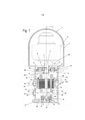
[0015] Fig. 1: uma vista em corte de um primeiro separador deacordo com a invenção, mostrado esquematicamente;[0015] Fig. 1: a sectional view of a first separator according to the invention, shown schematically;
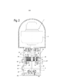
[0016] Fig. 2: uma vista em corte de um segundo separador deacordo com a invenção, mostrado esquematicamente.[0016] Fig. 2: a sectional view of a second separator according to the invention, shown schematically.
[0017] A figura 1 mostra um separador 1, com um tambor centrífugo 2 com eixo de rotação vertical D, que está envolvido por uma disposição de capota 3, a qual se apoia sobre uma caixa de acionamento 4 do tipo chassi de motor. A caixa de acionamento 4, de preferência em uma forma de execução, pode ser assentada em molas em uma fundação, através de elementos de base não mostrados aqui.[0017] Figure 1 shows a separator 1, with a
[0018] O tambor centrífugo 2 é mostrado aqui apenas esquematicamente. De preferência, ele é projetado para uma operação contínua para o tratamento contínuo e/ou separação de um produto fluido em uma ou duas fases líquidas e, eventualmente, uma fase de substâncias sólidas - especialmente em processo industrial. Para isso, de preferência, o seu espaço interno é provido de uma pilha de discos de separação. Também a disposição de capota 3 é mostrada apenas esquematicamente. Ela pode apresentar, particularmente, um coletor de substâncias sólidas, bem como uma ou mais passagens para dutos de entrada e de saída de produtos, não mostrados aqui. Essas características já são conhecidas há muito tempo pelos especialistas e não requerem nenhuma exposição mais detalhada aqui.[0018]
[0019] O tambor centrífugo cônico 2, de preferência simples ouduplo, está assentado sobre a extremidade, aqui superior vertical, de um fuso de acionamento 5. Esse fuso de acionamento 5 está apoiado giratoriamente por meio de uma disposição de mancal que, neste caso, apresenta um mancal de colar 6 e um mancal de base 7.[0019] The conical
[0020] Nesse caso, o mancal de colar 6 está apoiado radialmente,através de um elemento elástico, em uma caixa de mancal 9, a qual, por sua vez, está fixada na caixa de acionamento 4. Neste caso, a caixa de mancal 9 apresenta uma seção de flange 10, a qual repousa sobre um primeiro colar 11 - vertical superior - na circunferência interna da caixa de acionamento 4 e fica lá fixada, por meio de primeiros parafusos 12 que neste caso estão distribuídos pela circunferência. De preferência e vantajosamente, a caixa de mancal 9 e o mancal de colar formam uma unidade construtiva pré-montada e substituível. Neste caso, de preferência em uma forma simples de construção, o elemento elástico é formado por duas mangas metálicas 8’, 8’’’ que estão ligadas entre si por meio de um anel de material elastômero 8". Aqui, o anel externo, respectivamente a manga externa 8’, acha-se trabalhado externamente, de tal modo que ele seja conduzido na caixa com exatidão. De preferência, aqui, o elemento elástico encontra-se fixado, tal como, por exemplo, comprimido e, consequentemente, protegido axialmente e contra rotação conjunta. O anel interno, respectivamente a manga interna 8’’’, acha-se trabalhado internamente de tal modo que o mancal de rolamento, com seu anel externo, seja conduzido, de preferência, de modo deslocável.[0020] In this case, the collar bearing 6 is radially supported, through an elastic element, in a bearing housing 9, which, in turn, is fixed to the
[0021] Também são possíveis outras formas conhecidas de construção alternativas para esse apoio elástico de mancal de colar, tal como, por exemplo: êmbolo de suspensão com molas helicoidais, molas laminadas, molas pneumáticas etc.[0021] Other known forms of alternative construction for this elastic collar bearing support are also possible, such as, for example: suspension piston with helical springs, laminated springs, pneumatic springs etc.
[0022] De preferência, o mancal de colar 6 é projetado como man-cal de rolamento, o qual, neste caso, repousa sobre um anel 13, o qual, por sua vez, está assentado sobre o fuso 5 e lá repousa, dirigido para baixo, sobre uma gradação de diâmetro 14 do fuso 5. No elemento elástico, ele é conduzido de modo deslocável verticalmente e é apoiado radialmente.[0022] Preferably, the collar bearing 6 is designed as a rolling bearing, which, in this case, rests on a
[0023] O mancal de base 7 está projetado como mancal fixo axiale, de preferência, está disposto sobre o fuso de acionamento 5 com proteção contra torção. Além disso, ele está disposto na caixa de acionamento 4 (elemento de articulação 15) articuladamente através de anel interno 18 e anel externo 19, de modo cardânico inclinável, embora não giratoriamente em relação ao anel 18, e/ou ele próprio é projetado como mancal articulado, de tal modo que o fuso de acionamento 5 com o tambor possa seguir os movimentos de precessão do tambor centrífugo 2 durante o funcionamento.[0023] The base bearing 7 is designed as a fixed axial bearing and is preferably arranged on the drive spindle 5 with protection against torsion. Furthermore, it is arranged in the drive box 4 (joint element 15) articulately through
[0024] Neste caso, a proteção contra torção do mancal de base 7é obtida através de um pino 42 que está respectivamente inserido em uma abertura do anel interno 18 e da caixa de acionamento.[0024] In this case, the protection against torsion of the base bearing 7 is obtained through a
[0025] Nesse caso, o peso do tambor centrífugo com todas as peças de acionamento que estão ligadas com o fuso é apoiado, no essencial, na caixa de acionamento 4 através do mancal de base inferior 7. De modo correspondente, aqui é empregado, de preferência, um mancal de rolamento que pode absorver adequadamente as forças axiais surgidas. Para isso são adequados, por exemplo, mancais de esferas ranhurados e mancais de esferas inclinados. Em caso de necessidade, esses mancais também podem ser dispostos em pares quando assim o exigirem as forças a serem absorvidas.[0025] In this case, the weight of the centrifugal drum with all the drive parts that are connected with the spindle is essentially supported on the
[0026] O mancal articulado descrito assume, aqui, a capacidadede inclinação e o apoio cardânico.[0026] The articulated bearing described here assumes inclination capacity and cardanal support.
[0027] Toda a unidade constituída de mancal articulado e mancalde rolamento pode ser substituída por um mancal de esferas pendular ou mancal de rolos pendular, no caso de forças reduzidas a serem absorvidas, especialmente forças axiais.[0027] The entire unit consisting of articulated bearing and roller bearing can be replaced by a pendular ball bearing or pendular roller bearing, in the case of reduced forces to be absorbed, especially axial forces.
[0028] Aqui, o mancal de base 7, dirigido para cima, em sua circunferência interna, encosta em outra gradação de diâmetro 16 do fuso de acionamento 5 e, dirigido para baixo, em sua circunferência externa, encosta em uma gradação 17 de um anel interno 18 em forma de segmento de esfera na circunferência externa, anel este que, por sua vez, agarra articuladamente em um correspondente anel externo 19 moldado em forma complementar, o qual repousa sobre uma gradação 41 da caixa de acionamento 4.[0028] Here, the base bearing 7, directed upwards on its inner circumference, abuts another gradation of
[0029] Essa disposição é construída de modo compacto e possibilita, de modo fácil e seguro, o apoio do peso do tambor centrífugo 2 na caixa de acionamento 4 através do mancal de base.[0029] This arrangement is compactly constructed and makes it possible to easily and safely support the weight of the
[0030] Na região axial entre os mancais, servindo de dispositivo deacionamento encontra-se um motor elétrico 20 com um rotor 21 e um estator 22. Este se localiza totalmente entre o mancal de colar 6 e o mancal de base 7.[0030] In the axial region between the bearings, serving as a drive device, there is an
[0031] Nesse caso, o rotor 21 está disposto e fixado diretamentesobre o fuso de acionamento. Devido a isso, o rotor 21 e o fuso de acionamento giratório 5 se movem acoplados firmemente entre si, par-ticularmente também no caso de movimentos de precessão do fuso de acionamento 5 quando em operação. Aqui, o fuso de acionamento 5, em sua circunferência, pode apresentar um contorno apropriado - gradações, por exemplo - para a fixação, respectivamente disposição, do rotor 21.[0031] In this case, the
[0032] Nesse caso, o estator 22 está ligado firmemente com a caixa de acionamento 4. Com isso, altera-se a largura da fenda radial entre o estator 22 e o rotor 21 quando em operação, devido aos movimentos do fuso de acionamento 5.[0032] In this case, the
[0033] De fato, o fuso de acionamento 5 também executa seu movimento de precessão entre o mancal de colar 6 e o mancal de base 7 (como mancal fixo), devido às leis de centrifugação, embora esse movimento possa ser limitado de modo definido (batente) nessa região, de tal modo que com a ajuda de uma correspondente fenda de ar entre o estator 22 e o rotor de motor 21 seja possível assegurar que o rotor 21 e o estator 22 não se toquem quando em operação, apesar do movimento radial relativo. Tais movimentos relativos podem ocorrer e, eventualmente, ter seus maiores deslocamentos, por exemplo, devido a desbalanceamentos, especialmente na região da frequência de ressonância do sistema ao ocorrer a subida do tambor, ou, por exemplo, devido a movimentos de todo o motor devido à interferência de ondas no caso de uso a bordo de navios.[0033] In fact, the drive spindle 5 also performs its precession movement between the
[0034] A sustentação formada no mancal de base 7 (que, no essencial, assume o apoio axial do tambor centrífugo 2), projetado como contramancal, e no mancal de colar 6 apoiado elasticamente possibilita, de modo vantajoso quanto à frequência de ressonância, uma operação hipercrítica do rotor de motor 21 e do tambor centrífugo 2. As propriedades de massa do rotor de motor 21, nesse caso, são tão pequenas que não têm efeito negativo sobre o comportamento dinâmico do sistema de acionamento.[0034] The support formed in the base bearing 7 (which, in essence, assumes the axial support of the centrifugal drum 2), designed as a counter bearing, and in the
[0035] O separador de tambor, juntamente com o fuso e o apoiode mancal de colar, em uma primeira aproximação, forma um oscilador de uma massa que é excitado através do tambor em rotação e, especialmente, através do desbalanceamento que gira junto. O apoio elástico de mancal de colar abaixa nitidamente a sua própria frequência em relação às construções aproximadamente rígidas. Por número de rotações crítico (respectivamente frequência) designa-se aquele número de rotações, no qual as forças, provocadas pelo tambor em rotação e pelo desbalanceamento que gira junto, colocam o motor em vibrações de ressonância. (Aqui, a frequência de excitação (número de rotações do tambor) é igual à frequência própria do sistema.) Acima dessa frequência (número de rotações) o sistema se estabiliza, pois, aqui, o desbalanceamento e o centro de gravidade do rotor estão localizados em lados opostos do eixo de rotação real. Usualmente, separadores são operados com seus números de rotações de operação nitidamente acima do número de rotações crítico (frequência de ressonância), de tal modo que um maior desbalanceamento será suportado pelo motor sem efeitos prejudiciais.[0035] The drum separator, together with the spindle and the collar bearing support, in a first approximation, forms an oscillator of a mass that is excited through the rotating drum and especially through the unbalance that rotates together. The elastic collar bearing support markedly lowers its own frequency relative to approximately rigid constructions. Critical number of revolutions (respectively frequency) means that number of revolutions, in which the forces, caused by the rotating drum and the unbalance that rotates together, place the motor in resonance vibrations. (Here, the excitation frequency (number of revolutions of the drum) is equal to the system's own frequency.) Above this frequency (number of revolutions) the system stabilizes, because here the imbalance and the center of gravity of the rotor are located on opposite sides of the real axis of rotation. Usually, separators are operated with their number of operating revolutions clearly above the critical number of revolutions (resonance frequency), such that a greater unbalance will be supported by the motor without detrimental effects.
[0036] De preferência e em forma compacta, diferentemente doestado da técnica, todo o estator 22 com a região de enrolamento 23 com as cabeças de enrolamento e os pacotes de lâminas de estator 23’ e o corpo de manga 24 e, também, todo o rotor 21 estão dispostos axialmente entre o mancal de colar 6 e o mancal de base 7.[0036] Preferably and in compact form, unlike the art, the
[0037] Para a fixação do estator 22 na caixa de motor 4 é previstoaqui, de modo vantajoso, que a região de enrolamento 23, juntamente com o ou os pacotes de lâminas de estator 23’ do estator 22, seja envolvida por um corpo de manga 24 que - de preferência, em sua extremidade superior vertical - apresente uma seção de flange 25, a qual encoste, respectivamente, aqui, repouse, sobre uma correspondente seção de colar 26 na circunferência interna da caixa de acionamento 4. Para a fixação da seção de flange 25 e da seção de colar 26 são previstos meios adequados de fixação, que, neste caso, são um ou mais parafusos 27 (distribuídos perifericamente).[0037] For the attachment of the
[0038] No dimensionamento do estator é inicialmente particularmente vantajoso que o estator, de modo simples como pré-fabricado e como unidade pré-montada, possa ser fixado na caixa de acionamento por meio do corpo de manga 24 situado radialmente por fora.[0038] When dimensioning the stator, it is initially particularly advantageous that the stator, simply as prefabricated and as a pre-assembled unit, can be fixed to the drive box by means of the
[0039] Além disso, devido ao tipo escolhido de construção, é possível fixar motores (estatores 22 e rotores 21) de diferentes comprimentos e, consequentemente, de diferentes potências de motor de modo simples na seção de flange 25, o que também é mostrado por uma comparação entre as figuras 1 e 2.[0039] In addition, due to the chosen type of construction, it is possible to fix motors (
[0040] As construções das figuras 1 e 2 são amplamente iguaisem construção e se diferenciam, no essencial, apenas devido ao comprimento axial da construção dos motores elétricos 20 e 20’. Como se vê, o comprimento axial da construção dos motores elétricos 20, 20’ pode variar dentro de uma faixa considerável, o que possibilita, vanta- josamente, que sejam empregadas caixas de acionamento 4 iguais para motores elétricos 20, 20’ de diferentes comprimentos e potências.[0040] The constructions of figures 1 and 2 are largely the same in construction and differ, essentially, only due to the axial length of the construction of the
[0041] Uma comparação entre as figuras 1 e 2 torna evidente queno caso de estatores 22 com comprimentos diferentes, o corpo de manga 24 empregado como interface do estator 22 para a caixa de acionamento 4 apresenta, ainda assim, o mesmo comprimento vertical de construção. De preferência, emprega-se inclusive um corpo de manga 24 igual em construção, apesar de um comprimento vertical diferente.[0041] A comparison between figures 1 and 2 makes it evident that in the case of
[0042] O motor elétrico pode ser um motor assíncrono ou um motor síncrono.[0042] The electric motor can be an asynchronous motor or a synchronous motor.
[0043] De preferência e vantajosamente, o compartimento de acionamento 28 está projetado de modo amplamente fechado para cima (até uma fenda anelar 29 para o fuso de acionamento 5 acima do mancal de colar 6) e para baixo, bem como lateralmente.[0043] Preferably and advantageously, the
[0044] Em caso de necessidade de uma vedação de mais qualidade entre o compartimento de acionamento e o compartimento de tambor, pode-se empregar, adicionalmente à fenda anelar, uma vedação tipo labirinto ou uma vedação de anel ondulado de tipo conhecido (não mostradas aqui).[0044] In case of need for a higher quality seal between the drive compartment and the drum compartment, a labyrinth-type seal or a known-type wave-ring seal can be used, in addition to the annular gap (not shown on here).
[0045] O estator 22 e o rotor, respectivamente o rotor de motor 21,estão dispostos abertamente no compartimento de acionamento 28 entre o mancal de colar 6 e o mancal de base 7.[0045] The
[0046] Nas construções das figuras 1 e 2, são proporcionadas vantagens particulares também pela configuração das regiões funcionais "lubrificação" e "refrigeração dos componentes da região de acionamento e do lubrificante".[0046] In the constructions of figures 1 and 2, particular advantages are provided also by the configuration of the functional regions "lubrication" and "cooling of the components of the drive and lubricant region".
[0047] Em primeiro lugar será tratada detalhadamente a lubrificação.[0047] Firstly, lubrication will be dealt with in detail.
[0048] O fuso de acionamento 5 é projetado oco, respectivamente apresenta um duto ou perfuração de lubrificante 30 interno centralizado, o qual se estende axialmente a partir de uma região abaixo do mancal de base 7, através da região do rotor de motor 21 do motor elétrico 20, até a região do mancal de colar 6, onde, de preferência, o duto de lubrificante 30 desemboca no compartimento de acionamento 28 através de uma perfuração radial de entrada de lubrificante 31, a saber, de tal modo que com o lubrificante saído dessa perfuração 31 seja possível ocorrer uma lubrificação do mancal de colar 6.[0048] The drive spindle 5 is designed hollow, respectively features a centralized internal lubricant duct or
[0049] De preferência, a perfuração de entrada de lubrificante 31desemboca, portanto, acima do mancal de colar 6 no compartimento de acionamento. Alternativamente, ela também poderia desembocar pouco abaixo do mancal de colar 6 no compartimento de acionamento 28, se, desse modo, for garantida uma lubrificação suficiente do man- cal de colar 6.[0049] Preferably, the
[0050] À extremidade de fuso inferior (de preferência aberta) acha-se integrada, aqui, uma bomba de lubrificação (especialmente uma bomba de tubo de sucção ou uma bomba centrífuga; aqui, concretizada com uma disposição de aletas 32 na circunferência interna da extremidade inferior axial da perfuração de lubrificante 31). A disposição de aletas admite, juntamente com o dimensionamento do diâmetro de entrada, um controle (ajuste) particularmente preciso da quantidade de óleo e, eventualmente, pode ser ajustada ao lubrificante, respectivamente às condições de operação, tal como o local de montagem (temperatura ambiente), e pode ser projetada de modo a ser substituível.Integrated here to the lower (preferably open) spindle end is a lubrication pump (especially a suction tube pump or a centrifugal pump; here, embodied with an arrangement of
[0051] Já que a extremidade inferior de fuso do fuso de acionamento 5 com a bomba de lubrificação mergulha em um depósito de lubrificante 33, então, através do fuso de acionamento 5 e de seu duto 30 e da perfuração de entrada de lubrificante 31 ocorre, de modo simples e seguro, uma lubrificação do mancal de colar 6.[0051] Since the lower end of the drive spindle 5 spindle with the lube pump dips into a
[0052] O lubrificante (especialmente óleo) que passa através do mancal de colar 6 lubrificando este corre ou goteja para baixo no compartimento de acionamento 28.[0052] The lubricant (especially oil) that passes through the
[0053] Por isso, é vantajoso que abaixo do mancal de colar 6, entre este e o motor elétrico 20, sobre o fuso de acionamento 5 seja disposto o anel 13, o qual apresenta um colar radial 38, de tal modo que, quando em operação, ele forme um anel centrífugo, o qual centrifuga o lubrificante no compartimento de acionamento 28 radialmente para fora ao ocorrerem as rotações do fuso de acionamento 5, o que impede que o lubrificante possa gotejar diretamente no motor elétrico 20. Desse modo impede-se que o óleo através da fenda entre o estator 22 e o rotor 21 tome o caminho de volta para o depósito de óleo. O óleo corre junto à parede interna da caixa de acionamento 4 para baixo e através das perfurações de volta para o depósito de óleo, respectivamente depósito de lubrificante 33. O motor é mostrado aqui de modo esquemático, diferentemente à esquerda e à direita do eixo de rotação, para facilitar a compreensão.[0053] Therefore, it is advantageous that below the
[0054] De preferência, externamente ao estator 22 acham-se formadas uma ou mais perfurações ou similares, que correm especialmente verticalmente, servindo de canal de lubrificação 34 na seção de colar 26, em balanço radialmente para dentro, da caixa de motor 4, perfurações estas através das quais o lubrificante é conduzido, no essencial, radialmente por fora, em seu caminho para baixo, para dentro do depósito de lubrificante 33, passando junto ao estator 22 e ao rotor de motor 11.[0054] Preferably, external to the
[0055] O mancal de base 7 pode se encontrar totalmente abaixodo espelho de lubrificante no depósito de lubrificante 33, respectivamente pode estar disposto totalmente em banho de lubrificante.[0055] The
[0056] Geralmente, a temperatura da cabeça de enrolamento ébastante elevada. Neste caso, essas cabeças de enrolamento estão bem afastadas dos mancais, o que é uma vantagem em comparação com o estado da técnica. Já que, aqui, o mancal de base 7 está situado no depósito de óleo, então ele pode ser mantido refrigerado de modo particularmente satisfatório. Já que o mancal de colar 6 é lubrificado com lubrificante fluido, então ele também é melhor refrigerado do que no caso de uma lubrificação com névoa de óleo, tal como esta é conhecida pelo estado da técnica.[0056] Generally, the temperature of the winding head is quite high. In this case, these winding heads are well spaced from the bearings, which is an advantage compared to the prior art. Since here the
[0057] Nesse caso, o lubrificante pode correr através de outroscanais/perfurações 35 de volta para uma região do compartimento de acionamento 28 localizada abaixo do mancal de base 7, para poder entrar no duto 30. Opcionalmente, um parafuso de descarga 39 possibilita uma descarga/substituição do lubrificante.[0057] In this case, the lubricant can flow through other channels/
[0058] De preferência, o espelho de lubrificante se situa poucoabaixo do motor elétrico 20, sem entrar em contato com este.[0058] Preferably, the lubricant mirror is located just below the
[0059] A potência de calor resultante das perdas do motor elétricopode ser irradiada, por um lado, pela superfície da caixa de acionamento ou por uma ampliação de superfície correspondentemente configurada (por exemplo, aletas de refrigeração na área externa da caixa de acionamento 4, por todo o comprimento axial entre o mancal de colar e o mancal de base 7 em configuração correspondentemente grande). Alternativamente ou complementarmente é concebível conduzir agente de refrigeração através de canais e, eventualmente, câmaras na caixa de acionamento, para refrigerar o lubrificante.[0059] The heat power resulting from electric motor losses can be radiated, on the one hand, by the surface of the drive box or by a correspondingly configured surface enlargement (for example, cooling fins in the external area of
[0060] De preferência e de modo particularmente vantajoso, nessecaso, esse agente de refrigeração refrigera tanto o lubrificante, como também o motor elétrico (especialmente o estator 20).[0060] Preferably and particularly advantageously, in this case, this coolant cools both the lubricant and the electric motor (especially the stator 20).
[0061] Isso é concretizado aqui de modo simples, tal como se segue.[0061] This is accomplished here in a simple way, as follows.
[0062] Na caixa de acionamento das figuras 1 e 2 são previstosum duto de entrada de agente de refrigeração e um duto de saída de agente de refrigeração - 35, 36 - para um líquido de refrigeração ou para um gás de refrigeração, os quais desembocam em pelo menos uma câmara, de preferência uma câmara anelar 37, a qual se acha configurada na caixa de acionamento 4 ou, de modo particularmente simples e prático construtivamente, entre a caixa de acionamento 4 e seções do corpo de manga 24. Outros componentes, tais como uma bomba de refrigeração e, eventualmente, um filtro para completar o circuito de refrigeração não são mostrados aqui, já que são em si conhecidos.[0062] In the drive box of figures 1 and 2, a refrigerant inlet duct and a refrigerant outflow duct - 35, 36 - are provided for a refrigerant or for a refrigerant gas, which flow in at least one chamber, preferably an
[0063] Desse modo é refrigerado o lubrificante que corre atravésdo canal de lubrificante 34. Além disso, no entanto, também o estator 20 é refrigerado de modo particularmente efetivo. Sobre isso, cabe se remeter à figura 2 por uma questão de clareza.[0063] In this way the lubricant flowing through the
[0064] Na figura 2 fica evidente que a refrigeração do motor elétrico 20 ocorre, no essencial, através da câmara, especialmente da câmara anelar do circuito de refrigeração integrado à caixa de acionamento 4.[0064] In figure 2 it is evident that the cooling of the
[0065] O motor elétrico propriamente, por meio do corpo de manga24, também limita, de fato, aqui, a câmara de refrigeração, que neste caso é a câmara anelar 37. No entanto, ele próprio não precisa apresentar um sistema de refrigeração próprio. Isso simplifica a sua montagem e também a substituição que, além disso, se torna particularmente econômica devido a essa providência. O estator 22 do motor elétrico 20 propriamente pode ser disponibilizado e substituído, de modo particularmente simples, como módulo pré-fabricado. Também seria concebível limitar internamente a câmara anelar com uma manga adicional, o que, no entanto, é menos preferível.[0065] The electric motor itself, through the sleeve body24, also in fact limits the cooling chamber here, which in this case is the
[0066] Já que o circuito de refrigeração, em uma região, como, porexemplo, na região da câmara, especialmente da câmara anelar 37, é contíguo tanto ao estator 22 - aqui, ao corpo de manga 24 - como também próximo a pelo menos uma das perfurações do canal de lubri- ficante, que conduzem o lubrificante para baixo, como lubrificante líquido fluido, de volta para o depósito de lubrificante, passando junto ao motor elétrico, então se obtém, de modo fácil, uma refrigeração dupla. Nesse caso, vantajosamente, na circunferência interna do corpo de manga podem ser dispostas uma ou mais vedações 40, para vedar a fenda entre o corpo de manga 24 e a seção de colar 26 (respectivamente a câmara de refrigeração). Consequentemente, de modo particularmente simples construtivamente, o corpo de manga 24 forma uma das paredes da câmara anelar 37.[0066] Since the refrigeration circuit, in a region, such as, for example, in the chamber region, especially the
[0067] Visores de vidro 43 na parede externa permitem um controle visual especialmente do sistema de lubrificação, particularmente porque aqui um dos visores de vidro 43 se situa verticalmente na altura do nível máximo do lubrificante, de tal modo que o nível de lubrificante possa ser monitorado, sendo que um segundo (aqui, superior) visor de vidro 43 possibilita a visão para o canal de lubrificante 34 e, consequentemente, para o refluxo de óleo.[0067]
[0068] Já que o acionamento corre com pouco desgaste até omancal de colar e até o mancal de base 6, 7, então prescinde-se de uma grande parte do dispêndio usual com manutenção, o que reduz os custos operacionais.Lista de Números de Referência1 separador2 tambor centrífugo3 disposição de capota4 caixa de acionamento5 fuso de acionamento6 mancal de colar7 mancal de base8 , 8’’’ mangas8" elastômero 9 caixa de mancais10 seção de flange11 colar12 parafusos13 anel14 gradação de diâmetro15 elemento de articulação16 gradação de diâmetro17 gradação18 anel interno19 anel externo20 motor elétrico21 rotor22 estator23 região de enrolamento23’ pacote de lâminas de estator24 corpo de manga25 seção de flange26 seção de colar27 parafusos28 compartimento de acionamento29 fenda anelar30 duto de lubrificante31 perfuração de entrada de lubrificante32 aletas33 depósito de lubrificante34 canal de lubrificante35, 36 canais37 câmara anelar38 colar radialPetição 870200054636, de 04/05/2020, pág. 21/3317/1739 parafuso de descarga40 vedações41 gradação42 pino43 visores de vidroD eixo de rotação[0068] Since the drive runs with little wear to the collar bearing and up to the 6, 7 base bearing, then a large part of the usual maintenance expenditure is dispensed with, which reduces operating costs. Reference1 separator2 centrifugal drum3 hood arrangement4 drive housing5 drive spindle6 collar bearing7 base bearing8, 8''' sleeves8" elastomer 9 bearing housing10 flange section11 collar12 screws13 ring14 diameter grading15 articulating element16 diameter grading17 gradation18 inner ring19 ring external20 electric motor21 rotor22 stator23 winding region23' stator blade package24 sleeve body25 flange section26 collar section27 screws28 drive housing29 ring slot30 lubricant duct31 lubricant inlet drilling32 fins33 lubricant reservoir34 lubricant channel35, 36 channels37 annular chamber38 collar radial Petition 870200054636, of 05/04/2020,
Claims (22)
Applications Claiming Priority (3)
| Application Number | Priority Date | Filing Date | Title |
|---|---|---|---|
| DE102012110846.3A DE102012110846A1 (en) | 2012-11-12 | 2012-11-12 | Separator with direct drive |
| DE102012110846.3 | 2012-11-12 | ||
| PCT/EP2013/073117 WO2014072318A2 (en) | 2012-11-12 | 2013-11-06 | Separator with direct drive |
Publications (2)
| Publication Number | Publication Date |
|---|---|
| BR112015010479A2 BR112015010479A2 (en) | 2017-07-11 |
| BR112015010479B1 true BR112015010479B1 (en) | 2021-08-31 |
Family
ID=49582728
Family Applications (1)
| Application Number | Title | Priority Date | Filing Date |
|---|---|---|---|
| BR112015010479-7A BR112015010479B1 (en) | 2012-11-12 | 2013-11-06 | SEPARATOR WITH DIRECT ACTION |
Country Status (12)
| Country | Link |
|---|---|
| US (1) | US9981275B2 (en) |
| EP (1) | EP2916961B1 (en) |
| JP (1) | JP2016505352A (en) |
| KR (1) | KR20150084034A (en) |
| CN (1) | CN104797343A (en) |
| AU (1) | AU2013343679B2 (en) |
| BR (1) | BR112015010479B1 (en) |
| CA (1) | CA2889766C (en) |
| DE (1) | DE102012110846A1 (en) |
| RU (1) | RU2015121635A (en) |
| SG (1) | SG11201503572QA (en) |
| WO (1) | WO2014072318A2 (en) |
Families Citing this family (11)
| Publication number | Priority date | Publication date | Assignee | Title |
|---|---|---|---|---|
| SE533089C2 (en) * | 2008-05-13 | 2010-06-22 | Alfa Laval Corp Ab | centrifugal |
| SE532905C2 (en) * | 2008-09-22 | 2010-05-04 | Alfa Laval Corp Ab | centrifugal |
| DE102013100180A1 (en) * | 2012-03-26 | 2013-09-26 | Gea Mechanical Equipment Gmbh | separator arrangement |
| DE102012110846A1 (en) * | 2012-11-12 | 2014-05-15 | Gea Mechanical Equipment Gmbh | Separator with direct drive |
| EP3075455B1 (en) * | 2015-03-31 | 2017-12-06 | Alfa Laval Corporate AB | Cooling or heating of bearings in a centrifugal separator |
| DE102015108741A1 (en) * | 2015-06-02 | 2016-12-08 | Gea Mechanical Equipment Gmbh | separator |
| CN105057120A (en) * | 2015-09-11 | 2015-11-18 | 戴杰 | Rotating drum lower bearing device |
| DE102017114649A1 (en) | 2017-06-30 | 2019-01-03 | Gea Mechanical Equipment Gmbh | Separator with direct drive |
| DE102017215784A1 (en) * | 2017-09-07 | 2019-03-07 | Zf Friedrichshafen Ag | Transmission for a motor vehicle |
| EP3878559A1 (en) | 2020-03-12 | 2021-09-15 | Alfa Laval Corporate AB | A centrifugal separator |
| DE102022117310A1 (en) | 2022-07-12 | 2024-01-18 | Gea Westfalia Separator Group Gmbh | Method for monitoring and controlling the coolant temperature of a drive device of a separator |
Family Cites Families (51)
| Publication number | Priority date | Publication date | Assignee | Title |
|---|---|---|---|---|
| DE513192C (en) | 1930-11-24 | Ramesohl & Schmidt Akt Ges | Divided spin spindle | |
| DE570729C (en) * | 1929-06-07 | 1933-02-20 | Siemens Schuckertwerke Akt Ges | Extractor driven by an electric motor |
| GB368247A (en) | 1929-08-31 | 1932-03-03 | Gen Electric | Improvements in and relating to methods of mounting high speed shafts |
| US2597405A (en) * | 1946-09-28 | 1952-05-20 | American Tool & Machine Co | Combined bearing and stabilizing mechanism for centrifugal separators |
| BE554838A (en) | 1956-02-26 | |||
| FR1287551A (en) | 1961-02-02 | 1962-03-16 | Garin Ets | Device such as cream separator |
| US3257235A (en) * | 1961-10-09 | 1966-06-21 | American Factors Ass Ltd | Shaft lubrication system for continuous centrifugal |
| US3318644A (en) * | 1965-02-24 | 1967-05-09 | Gen Motors Corp | Centrifugal bearing lubrication system |
| US3604769A (en) | 1968-09-23 | 1971-09-14 | Cryogenic Technology Inc | Temperature-controlled spindle for centrifuges and similar apparatus |
| JPS50144367U (en) * | 1974-05-16 | 1975-11-28 | ||
| US4226359A (en) * | 1979-03-14 | 1980-10-07 | Beckman Instruments, Inc. | Direct drive high speed ultracentrifuge |
| US4322030A (en) * | 1979-03-14 | 1982-03-30 | Beckman Instruments, Inc. | Lubrication and cooling system for a high speed ultracentrifuge drive assembly |
| US4541736A (en) | 1984-04-30 | 1985-09-17 | Beckman Instruments, Inc. | Centrifugal oil pump flow proportioning and cooling system |
| SE8504132D0 (en) * | 1985-09-05 | 1985-09-05 | Alfa Laval Separation Ab | STORAGE LUBRICATION DEVICE BY A Centrifugal Separator |
| US4652782A (en) | 1986-03-31 | 1987-03-24 | Sundstrand Corporation | Flanged stator assembly for dynamoelectric machine |
| SU1704839A1 (en) * | 1988-07-18 | 1992-01-15 | Московское научно-производственное объединение "Биофизприбор" | Ultracentrifuge drive |
| DE4314440C1 (en) | 1993-05-03 | 1994-06-16 | Kyffhaeuser Maschf Artern Gmbh | High torque centrifuge - has rotating components inelastically suspended with rotating system, bearing bridge, motor stator, joined as single constructional and vibrational unit |
| DE4408182C1 (en) | 1994-03-11 | 1995-05-11 | Westfalia Separator Ag | Drive for a centrifuge drum |
| JP3613477B2 (en) * | 1994-04-08 | 2005-01-26 | 日立工機株式会社 | Bearing lubrication and cooling equipment |
| US5980222A (en) * | 1997-11-13 | 1999-11-09 | Tecumseh Products Company | Hermetic reciprocating compressor having a housing divided into a low pressure portion and a high pressure portion |
| SE510204C2 (en) * | 1997-06-16 | 1999-05-03 | Alfa Laval Ab | Apparatus and means for cooling a bearing |
| SE9702290D0 (en) * | 1997-06-16 | 1997-06-16 | Alfa Laval Ab | Sealing device for a centrifugal separator |
| SE509516C2 (en) * | 1997-06-16 | 1999-02-08 | Alfa Laval Ab | Apparatus for supplying a liquid at a bearing to a rotating shaft |
| SE521062C2 (en) * | 1999-03-08 | 2003-09-30 | Alfa Laval Corp Ab | A centrifuge rotor drive unit of a centrifugal separator |
| SE513789C2 (en) * | 1999-03-08 | 2000-11-06 | Alfa Laval Ab | A centrifuge rotor drive unit of a centrifugal separator |
| SE521030C2 (en) * | 1999-03-08 | 2003-09-23 | Alfa Laval Corp Ab | Lubricating oil supply device for a centrifugal separator |
| SE514135C2 (en) * | 1999-04-07 | 2001-01-08 | Alfa Laval Ab | Method and apparatus for separating a surface layer of a liquid body |
| JP2000352414A (en) | 1999-06-11 | 2000-12-19 | Ntn Corp | Dynamic pressure type bearing unit |
| JP2001125453A (en) * | 1999-10-28 | 2001-05-11 | Ricoh Co Ltd | Image forming device |
| US6527085B1 (en) * | 2000-11-14 | 2003-03-04 | Tecumseh Products Company | Lubricating system for compressor |
| US6364822B1 (en) * | 2000-12-07 | 2002-04-02 | Fleetguard, Inc. | Hero-turbine centrifuge with drainage enhancing baffle devices |
| GB0114420D0 (en) * | 2001-06-13 | 2001-08-08 | Boc Group Plc | Improved lubrication system for rotating machines and pumps |
| DE10212808B4 (en) * | 2002-03-22 | 2004-07-29 | Westfalia Separator Ag | separator |
| DE10314118B4 (en) * | 2003-03-28 | 2005-05-12 | Westfalia Separator Ag | Drive device for a separator |
| SE526010C2 (en) * | 2003-04-08 | 2005-06-14 | Alfa Laval Corp Ab | A centrifugal separator drive device |
| JP2006021121A (en) | 2004-07-08 | 2006-01-26 | Hitachi Koki Co Ltd | Centrifugal separator |
| DE202005001716U1 (en) * | 2005-02-03 | 2006-10-05 | Westfalia Separator Ag | Lubrication system for a centrifuge drive |
| DE102006011895A1 (en) | 2006-03-15 | 2007-09-20 | Westfalia Separator Ag | Separator arrangement in sanitary design |
| DE102006020467A1 (en) | 2006-04-28 | 2007-10-31 | Westfalia Separator Ag | Separator for use in industrial application, has stator rigidly connected with machine frame, and rotor, drive spindle, centrifuge barrel and housing forming flexible unit supported at machine frame |
| SE530223C2 (en) * | 2006-05-15 | 2008-04-01 | Alfa Laval Corp Ab | centrifugal |
| EP1927688A1 (en) * | 2006-11-30 | 2008-06-04 | Maschinenfabrik Rieter Ag | Support arrangements for spindel assemblies in ring spinning machines of the Individual-spindle-drive type |
| DE102007060588A1 (en) * | 2007-12-13 | 2009-06-18 | Gea Westfalia Separator Gmbh | Separator with a direct drive |
| CN101896281B (en) * | 2007-12-13 | 2013-12-04 | Gea韦斯伐里亚分离机有限公司 | Separator having a lubrication system for a short spindle drive |
| SE533276C2 (en) * | 2008-12-19 | 2010-08-10 | Alfa Laval Corp Ab | Centrifugal separator with lubrication device |
| JP5024277B2 (en) * | 2008-12-24 | 2012-09-12 | 日産自動車株式会社 | Installation method of motor for vehicle |
| DE102009022972A1 (en) * | 2009-05-28 | 2010-12-02 | Gea Westfalia Separator Gmbh | Centrifuge with a lubricant system |
| EP2537235B1 (en) | 2010-02-19 | 2015-04-22 | Magna Powertrain AG & Co. KG | Electric drive unit |
| JP5513297B2 (en) * | 2010-04-28 | 2014-06-04 | アスモ株式会社 | motor |
| DE102011107158A1 (en) * | 2011-07-14 | 2013-01-17 | Gea Mechanical Equipment Gmbh | centrifuge |
| DE102013100180A1 (en) * | 2012-03-26 | 2013-09-26 | Gea Mechanical Equipment Gmbh | separator arrangement |
| DE102012110846A1 (en) * | 2012-11-12 | 2014-05-15 | Gea Mechanical Equipment Gmbh | Separator with direct drive |
-
2012
- 2012-11-12 DE DE102012110846.3A patent/DE102012110846A1/en not_active Withdrawn
-
2013
- 2013-11-06 BR BR112015010479-7A patent/BR112015010479B1/en active IP Right Grant
- 2013-11-06 JP JP2015541110A patent/JP2016505352A/en active Pending
- 2013-11-06 CA CA2889766A patent/CA2889766C/en active Active
- 2013-11-06 AU AU2013343679A patent/AU2013343679B2/en active Active
- 2013-11-06 SG SG11201503572QA patent/SG11201503572QA/en unknown
- 2013-11-06 EP EP13789760.9A patent/EP2916961B1/en active Active
- 2013-11-06 KR KR1020157014859A patent/KR20150084034A/en not_active Application Discontinuation
- 2013-11-06 CN CN201380058692.9A patent/CN104797343A/en active Pending
- 2013-11-06 US US14/442,064 patent/US9981275B2/en active Active
- 2013-11-06 WO PCT/EP2013/073117 patent/WO2014072318A2/en active Application Filing
- 2013-11-06 RU RU2015121635A patent/RU2015121635A/en not_active Application Discontinuation
Also Published As
| Publication number | Publication date |
|---|---|
| CA2889766A1 (en) | 2014-05-15 |
| CN104797343A (en) | 2015-07-22 |
| BR112015010479A2 (en) | 2017-07-11 |
| AU2013343679B2 (en) | 2018-04-19 |
| RU2015121635A (en) | 2017-01-10 |
| WO2014072318A3 (en) | 2014-09-18 |
| US20150283561A1 (en) | 2015-10-08 |
| US9981275B2 (en) | 2018-05-29 |
| DE102012110846A1 (en) | 2014-05-15 |
| EP2916961A2 (en) | 2015-09-16 |
| WO2014072318A2 (en) | 2014-05-15 |
| SG11201503572QA (en) | 2015-06-29 |
| KR20150084034A (en) | 2015-07-21 |
| EP2916961B1 (en) | 2019-10-09 |
| JP2016505352A (en) | 2016-02-25 |
| AU2013343679A1 (en) | 2015-05-21 |
| CA2889766C (en) | 2020-06-02 |
Similar Documents
| Publication | Publication Date | Title |
|---|---|---|
| BR112015010479B1 (en) | SEPARATOR WITH DIRECT ACTION | |
| JP2016505352A5 (en) | ||
| JP6647203B2 (en) | Bearing device for centrifuge | |
| BRPI0707129A2 (en) | cooling of rotary bearings, motors and other heat generating components | |
| US20110085754A1 (en) | Auxiliary bearing system with oil reservoir for magnetically supported rotor system | |
| BRPI0710958A2 (en) | direct drive separator | |
| US4946433A (en) | Centrifuge drive | |
| WO2015054108A1 (en) | Self scavenging gear shield | |
| BR112014023659B1 (en) | separating device and process for operating it | |
| GB2277561A (en) | Shaft sealing arrangement | |
| RU2005134363A (en) | DRIVE DEVICE FOR CENTRIFUGAL SEPARATOR | |
| US9217436B2 (en) | Impeller fan assembly | |
| EP0017344B1 (en) | A direct drive high speed ultracentrifuge | |
| JP2013541669A (en) | Vacuum pump | |
| US10240609B2 (en) | Screw pump and impeller fan assemblies and method of operating | |
| CN108979779B (en) | Engine lubricating oil circulation system | |
| CN201735510U (en) | Self-cooled vibration exciter | |
| CN101912841B (en) | Self-cooled type vibration exciter | |
| US4345884A (en) | Pump drive | |
| BR112014028789B1 (en) | SEPARATOR WITH A SEPARATOR DRUM | |
| US2448297A (en) | Liquid rotor spray mechanism | |
| KR100868896B1 (en) | Foil bearing and motor thereby | |
| CN103821722A (en) | Compressor | |
| CN110966200B (en) | Compressor and air conditioner with same | |
| WO2017029852A1 (en) | Vertical bearing device |
Legal Events
| Date | Code | Title | Description |
|---|---|---|---|
| B06F | Objections, documents and/or translations needed after an examination request according [chapter 6.6 patent gazette] | ||
| B06U | Preliminary requirement: requests with searches performed by other patent offices: procedure suspended [chapter 6.21 patent gazette] | ||
| B09A | Decision: intention to grant [chapter 9.1 patent gazette] | ||
| B16A | Patent or certificate of addition of invention granted [chapter 16.1 patent gazette] |
Free format text: PRAZO DE VALIDADE: 20 (VINTE) ANOS CONTADOS A PARTIR DE 06/11/2013, OBSERVADAS AS CONDICOES LEGAIS. |