BR112015010132B1 - TAPERED GEAR FACE CUTTER HEAD FOR MILLING AND FACING TAPERED AND HYPOID GEARS AND GRINDING METHOD AT LEAST ONE CUTTING BLADE POSITIONED ON A TAPERED GEAR FACE CUTTER HEAD - Google Patents
TAPERED GEAR FACE CUTTER HEAD FOR MILLING AND FACING TAPERED AND HYPOID GEARS AND GRINDING METHOD AT LEAST ONE CUTTING BLADE POSITIONED ON A TAPERED GEAR FACE CUTTER HEAD Download PDFInfo
- Publication number
- BR112015010132B1 BR112015010132B1 BR112015010132-1A BR112015010132A BR112015010132B1 BR 112015010132 B1 BR112015010132 B1 BR 112015010132B1 BR 112015010132 A BR112015010132 A BR 112015010132A BR 112015010132 B1 BR112015010132 B1 BR 112015010132B1
- Authority
- BR
- Brazil
- Prior art keywords
- blade
- cutter head
- seating surface
- cutting blade
- extending
- Prior art date
Links
- 238000005520 cutting process Methods 0.000 title claims abstract description 61
- 238000000034 method Methods 0.000 title claims description 14
- 238000000227 grinding Methods 0.000 title claims description 3
- 238000003801 milling Methods 0.000 claims abstract description 10
- 230000008859 change Effects 0.000 claims description 12
- 238000007493 shaping process Methods 0.000 claims 5
- 230000010355 oscillation Effects 0.000 claims 2
- 238000005096 rolling process Methods 0.000 claims 1
- 238000004519 manufacturing process Methods 0.000 abstract description 4
- 230000004048 modification Effects 0.000 description 13
- 238000012986 modification Methods 0.000 description 13
- 230000000694 effects Effects 0.000 description 5
- 239000011159 matrix material Substances 0.000 description 5
- 238000007373 indentation Methods 0.000 description 3
- 230000008569 process Effects 0.000 description 3
- 229910000831 Steel Inorganic materials 0.000 description 2
- 239000000463 material Substances 0.000 description 2
- 230000009467 reduction Effects 0.000 description 2
- 239000010959 steel Substances 0.000 description 2
- 230000001174 ascending effect Effects 0.000 description 1
- 230000008901 benefit Effects 0.000 description 1
- 238000010276 construction Methods 0.000 description 1
- 230000007423 decrease Effects 0.000 description 1
- 238000006073 displacement reaction Methods 0.000 description 1
- 230000002028 premature Effects 0.000 description 1
- 238000000926 separation method Methods 0.000 description 1
Images


Classifications
-
- B—PERFORMING OPERATIONS; TRANSPORTING
- B23—MACHINE TOOLS; METAL-WORKING NOT OTHERWISE PROVIDED FOR
- B23C—MILLING
- B23C5/00—Milling-cutters
- B23C5/16—Milling-cutters characterised by physical features other than shape
- B23C5/20—Milling-cutters characterised by physical features other than shape with removable cutter bits or teeth or cutting inserts
- B23C5/22—Securing arrangements for bits or teeth or cutting inserts
- B23C5/24—Securing arrangements for bits or teeth or cutting inserts adjustable
- B23C5/2489—Securing arrangements for bits or teeth or cutting inserts adjustable where the adjustment is made by changing the inclination of the inserts
-
- B—PERFORMING OPERATIONS; TRANSPORTING
- B23—MACHINE TOOLS; METAL-WORKING NOT OTHERWISE PROVIDED FOR
- B23C—MILLING
- B23C5/00—Milling-cutters
- B23C5/16—Milling-cutters characterised by physical features other than shape
- B23C5/20—Milling-cutters characterised by physical features other than shape with removable cutter bits or teeth or cutting inserts
- B23C5/22—Securing arrangements for bits or teeth or cutting inserts
- B23C5/24—Securing arrangements for bits or teeth or cutting inserts adjustable
- B23C5/2472—Securing arrangements for bits or teeth or cutting inserts adjustable the adjusting means being screws
-
- B—PERFORMING OPERATIONS; TRANSPORTING
- B23—MACHINE TOOLS; METAL-WORKING NOT OTHERWISE PROVIDED FOR
- B23C—MILLING
- B23C5/00—Milling-cutters
- B23C5/16—Milling-cutters characterised by physical features other than shape
- B23C5/20—Milling-cutters characterised by physical features other than shape with removable cutter bits or teeth or cutting inserts
- B23C5/22—Securing arrangements for bits or teeth or cutting inserts
- B23C5/24—Securing arrangements for bits or teeth or cutting inserts adjustable
- B23C5/2493—Securing arrangements for bits or teeth or cutting inserts adjustable where the adjustment is made by deforming the seating surfaces
-
- B—PERFORMING OPERATIONS; TRANSPORTING
- B23—MACHINE TOOLS; METAL-WORKING NOT OTHERWISE PROVIDED FOR
- B23F—MAKING GEARS OR TOOTHED RACKS
- B23F21/00—Tools specially adapted for use in machines for manufacturing gear teeth
- B23F21/12—Milling tools
- B23F21/126—Milling tools with inserted cutting elements
- B23F21/128—Milling tools with inserted cutting elements in exchangeable arrangement
-
- B—PERFORMING OPERATIONS; TRANSPORTING
- B23—MACHINE TOOLS; METAL-WORKING NOT OTHERWISE PROVIDED FOR
- B23F—MAKING GEARS OR TOOTHED RACKS
- B23F21/00—Tools specially adapted for use in machines for manufacturing gear teeth
- B23F21/12—Milling tools
- B23F21/22—Face-mills for longitudinally-curved gear teeth
- B23F21/223—Face-mills for longitudinally-curved gear teeth with inserted cutting elements
- B23F21/226—Face-mills for longitudinally-curved gear teeth with inserted cutting elements in exchangeable arrangement
-
- B—PERFORMING OPERATIONS; TRANSPORTING
- B23—MACHINE TOOLS; METAL-WORKING NOT OTHERWISE PROVIDED FOR
- B23C—MILLING
- B23C2210/00—Details of milling cutters
- B23C2210/16—Fixation of inserts or cutting bits in the tool
- B23C2210/165—Fixation bolts
Landscapes
- Engineering & Computer Science (AREA)
- Mechanical Engineering (AREA)
- Milling Processes (AREA)
- Gear Processing (AREA)
- Details Of Cutting Devices (AREA)
- Knives (AREA)
Abstract
cortador de engrenagem com ajustabilidade radial de lâminas retas. a presente invenção refere-se a um cabeçote de cortador de face para fabricação de engrenagem cônica (2) para fresagem e faceamento em que o cabeçote de cortador compreende superfícies de sede de lâmina positiva (16, 18) e a capacidade de prender as lâminas (8) apertadas nas superfícies de sede positiva e ajustar as lâminas de corte radialmente após serem pré-presas e estarem axialmente localizadas.gear cutter with radial adjustability of straight blades. The present invention relates to a face cutter head for manufacturing bevel gear (2) for milling and face milling wherein the cutter head comprises positive blade seat surfaces (16, 18) and the ability to clamp blades (8) tightened onto the positive seating surfaces and adjust the cutting blades radially after they are pre-clamped and axially located.
Description
[001] O presente pedido reivindica o benefício de Pedido de Patente Provisório dos Estados Unidos N° 61/724.531, depositado em 9 de novembro de 2012, toda descrição do qual é aqui incorporada através de referência.[001] The present application claims the benefit of United States Provisional Patent Application No. 61/724,531, filed November 9, 2012, the entire description of which is incorporated herein by reference.
[002] A presente invenção refere-se à fabricação de engrenagens e, em particular, a um cabeçote de cortador de face de engrenagem cônica para fresagem e faceamento.[002] The present invention relates to the manufacture of gears and, in particular, to a bevel gear face cutter head for milling and face milling.
[003] Engrenagens cônicas e hipoides podem ser cortadas em um processo de indexação único ou intermitente (faceamento) ou de um processo de indexação contínua (fresagem). Uma configuração de corte básica no plano de geração ou oscilante colocará o centro do cabeçote de cortador em uma posição que está longe do centro da engrenagem (eixo de balanço) pela quantidade da chamada distância radial. A silhueta das lâminas de cortador representa um dente da engrenagem geradora enquanto o cortador gira. Cortadores de face comuns para corte de engrenagem cônica têm diversos grupos de lâminas, com cada grupo tendo entre uma e quatro lâminas. Os cortadores mais comuns são cortadores alternados (para completar) com uma lâmina externa e uma interna por grupo de lâminas. A fim de obter uma carga de aparas iguais de todas as lâminas internas e de todas as lâminas externas durante os processos de corte, as bordas de corte de todas as lâminas externas, de preferência, seguem uma à outra na mesma posição radial. Também todas as lâminas internas devem seguir uma à outra na mesma posição radial. Em outras palavras, todas as bordas de corte de uma espécie (internas ou externas) gerarão a mesma superfície de cone, enquanto o cortador está girando.[003] Bevel and hypoid gears can be cut in a single or intermittent indexing process (face milling) or a continuous indexing process (milling). A basic cutting configuration in the generation or oscillating plane will place the center of the cutter head in a position that is far from the center of the gear (balance axis) by the amount of the so-called radial distance. The silhouette of the cutter blades represents a cog in the sprocket as the cutter rotates. Common face cutters for bevel gear cutting have several groups of blades, with each group having between one and four blades. The most common cutters are alternate cutters (to complete) with one outer and one inner blade per blade group. In order to obtain an equal chip load of all inner blades and all outer blades during the cutting processes, the cutting edges of all outer blades preferably follow each other in the same radial position. Also all inner blades must follow each other in the same radial position. In other words, all cutting edges of a species (internal or external) will generate the same cone surface while the cutter is rotating.
[004] Tolerâncias de fabricação do corpo de cabeçote de cortador, os esboços de lâminas e os desvios na retificação de perfil de lâmina introduzirão diferentes localizações de bordas de corte para as diferentes lâminas em um cabeçote de cortador.[004] Cutter head body manufacturing tolerances, blade sketches and deviations in blade profile grinding will introduce different cutting edge locations for different blades in a cutter head.
[005] Embora sistemas de cortadores de face mais antigos permitissem um ajuste da posição radial da lâmina, os sistemas de lâminas retas de hoje não têm disposições a fim de realizar um ajuste radial direto. Contudo, técnicas conhecidas que obtêm uma mudança radial da localização da borda de corte incluem:[005] Although older face cutter systems allowed an adjustment of the radial position of the blade, today's straight blade systems do not have provisions in order to perform a direct radial adjustment. However, known techniques that achieve a radial shift of the cutting edge location include:
[006] 1. Se uma lâmina reta for movida em uma posição radial, que é diferente da posição nominal, então, o raio no plano de referência do cortador aumenta ou reduz em aproximadamente ΔR = Δs • tan α, onde Δs é um movimento axial positivo ou negativo da lâmina reta e α é o ângulo de pressão de lâmina (por exemplo, veja a norte-americana 5.839.943).[006] 1. If a straight blade is moved in a radial position, which is different from the nominal position, then the radius in the cutter reference plane increases or decreases by approximately ΔR = Δs • tan α, where Δs is a movement positive or negative axial of the straight blade and α is the blade pressure angle (for example, see US 5,839,943).
[007] 2. Se uma lâmina reta for presa com dois parafusos de fixação (superior e inferior), então, o aumento do torque do parafuso superior ou inferior pode mover a ponta da lâmina ligeiramente de modo radial, se a lâmina reta não for exatamente reta ou se a fenda normal não for exatamente plana.[007] 2. If a straight blade is secured with two fastening screws (top and bottom), then increasing the torque of the upper or lower screw may move the blade tip slightly radially, if the straight blade is not exactly straight or if the normal slit is not exactly flat.
[008] A desvantagem do Método 1 acima é que as pontas das lâminas de todas as lâminas deslocadas axialmente serão movidas para fora de seu plano de ponta comum. Embora o ajuste da lâmina aperfeiçoe a localização radial da borda de corte, ele causa uma imprecisão das pontas das lâminas. A imprecisão das pontas de lâminas contribuirá para o desgaste prematuro das pontas das lâminas.[008] The disadvantage of Method 1 above is that the blade tips of all axially displaced blades will be moved out of their common nose plane. Although blade adjustment improves the radial location of the cutting edge, it causes an inaccuracy of the blade tips. Inaccuracy of the blade tips will contribute to premature wear of the blade tips.
[009] A desvantagem do Método 2 acima é que o cortador requer dois parafusos de fixação por lâmina e que o torque daqueles dois parafusos de fixação tem que ser escolhido, dependendo da imprecisão individual da lâmina e da fenda. Também é possível que, devido à forma particular da lâmina e da fenda, nenhuma mudança no raio da lâmina, tal como um aumento do raio de lâmina ou uma redução do raio de lâmina ocorrerá. Nesse caso, um ajuste dessa combinação particular de fenda/ lâmina poderia não ser possível. O Método 2 é baseado em coincidências, que só podem ser controladas por laços de tentativa e erro consumidores de tempo.[009] The disadvantage of
[0010] A presente invenção é dirigida a um cabeçote de cortador de face de fabricação de engrenagem cônica para fresagem e faceamento, em que o cabeçote de cortador compreende sede de lâmina positiva e a capacidade de prender as lâminas apertadas nas superfícies de sede positivas e ajustar as lâminas retas radialmente, após elas serem pré- presas e localizadas axialmente.[0010] The present invention is directed to a bevel gear fabrication face cutter head for milling and face milling, wherein the cutter head comprises positive blade seat and the ability to grip blades clamped on positive seat surfaces and adjust the blades straight radially after they are pre-clamped and located axially.
[0011] O cabeçote de cortador da invenção é, em geral, em forma de disco e girável em torno de um eixo de cabeçote de cortador. O cabeçote de cortador compreende um primeiro lado e um segundo lado, uma ou mais fendas de posicionamento de lâminas de corte, dispostas no cabeçote de cortador, com cada uma das fendas de posicionamento de lâminas se estendendo entre os primeiro e segundo lados. As fendas de posicionamento de lâminas têm, cada uma delas, pelo menos uma superfície de sede de lâmina que se estende entre os referidos primeiro e segundo lados, com a superfície de sede de lâmina tendo uma formas modificada e se estendendo do primeiro lado até o segundo lado, em que a forma modificada se afasta da forma de uma superfície de sede moldada em linha reta contínua, estendendo-se do primeiro lado até o segundo lado.[0011] The cutter head of the invention is generally disk-shaped and swivelable around a cutter head axis. The cutter head comprises a first side and a second side, one or more cutting blade positioning slots disposed in the cutter head, with each of the blade positioning slots extending between the first and second sides. The blade positioning slots each have at least one blade seating surface extending between said first and second sides, with the blade seating surface having a modified shape and extending from the first side to the second side, wherein the modified shape deviates from the shape of a molded seating surface in a continuous straight line, extending from the first side to the second side.
[0012] De preferência, a superfície de sede de forma modificada inclui uma primeira porção que se estende de um dos primeiro ou segundo lados até uma localização predeterminada entre os primeiro e segundo lados, com a primeira porção tendo uma primeira forma e uma segunda porção estendendo-se da localização predeterminada até o outros dos primeiro ou segundo lados, com a segunda porção tendo uma forma tal que a forma da primeira porção e a forma da segunda porção juntas não descrevem uma linha reta contínua (a mesma inclinação sempre) estendendo-se do primeiro lado até o segundo lado. A primeira porção, de preferência, é reta e a segunda porção, de preferência, é curva.[0012] Preferably, the seating surface of modified form includes a first portion extending from one of the first or second sides to a predetermined location between the first and second sides, with the first portion having a first shape and a second portion. extending from the predetermined location to the other of the first or second sides, with the second portion having a shape such that the shape of the first portion and the shape of the second portion together do not describe a continuous straight line (the same slope always) extending. from the first side to the second side. The first portion is preferably straight and the second portion is preferably curved.
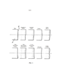
[0013] A figura 1 mostra uma pluralidade de diferentes modificações de superfície de sede das fendas de cabeçote de cortador para lâminas retas.[0013] Figure 1 shows a plurality of different seat surface modifications of cutter head slots for straight blades.
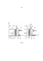
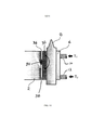
[0014] A figura 2(a) mostra a mesma seção transversal de um cabeçote de cortador om uma lâmina reta, que é conectada ao cabeçote de cortador com um bloco de fixação e dois parafusos de fixação com apenas com apenas o parafuso de fixação superior estando sob torque.[0014] Figure 2(a) shows the same cross-section of a cutter head with a straight blade, which is connected to the cutter head with a clamping block and two clamping screws with just the top clamping screw being under torque.
[0015] A figura 2(b) mostra a mesma seção transversal que a figura 2(a) com o parafuso de fixação inferior tendo um torque maior do que o parafuso de fixação superior.[0015] Figure 2(b) shows the same cross section as figure 2(a) with the lower clamping bolt having a higher torque than the upper clamping bolt.
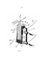
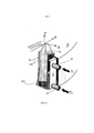
[0016] A figura 3 mostra uma vista tridimensional de uma lâmina de corte com uma seção transversal em forma de pentágono e sede positiva em uma fenda de cabeçote de cortador. As seções inferiores de ambas as superfícies de sede de lâminas são modificadas.[0016] Figure 3 shows a three-dimensional view of a cutting blade with a pentagon-shaped cross section and positive seat in a cutter head slot. The lower sections of both blade seating surfaces are modified.
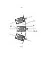
[0017] A figura 4 mostra uma vista de topo bidimensional de uma lâmina de corte com uma seção transversal em forma de pentágono em uma fenda de cabeçote de cortador. As linhas tracejadas indicam a modificação de ambas as superfícies de sede na seção inferior (não visível) das superfícies de sede.[0017] Figure 4 shows a two-dimensional top view of a cutting blade with a pentagon-shaped cross section in a cutter head slot. The dashed lines indicate the modification of both seating surfaces in the lower (not visible) section of the seating surfaces.
[0018] A figura 5 mostra uma vista de topo bidimensional de uma lâmina de corte com uma seção transversal em forma de pentágono em uma fenda de cabeçote de cortador. As linhas tracejadas indicam a modificação da superfície de sede, que é, mais tangencialmente ao círculo de corte, orientada na seção inferior (não visível) da superfície de sede.[0018] Figure 5 shows a two-dimensional top view of a cutting blade with a pentagon-shaped cross section in a cutter head slot. The dashed lines indicate the modification of the seating surface, which is, more tangentially to the cutting circle, oriented in the lower (not visible) section of the seating surface.
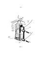
[0019] A figura 6 mostra uma vista tridimensional de uma lâmina de corte com uma seção transversal em forma de pentágono e colocação positiva em uma fenda de cabeçote de cortador. As seções inferiores da superfície de sede, que é mais tangencialmente ao círculo de corte orientada são modificadas.[0019] Figure 6 shows a three-dimensional view of a cutting blade with a pentagon-shaped cross section and positive placement in a cutter head slot. The lower sections of the seating surface, which is more tangential to the oriented cutting circle, are modified.
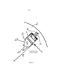
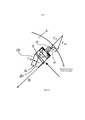
[0020] A figura 7 mostra uma vista tridimensional de uma lâmina de corte com uma seção transversal em forma de pentágono e uma sede positiva em uma fenda de cabeçote de cortador. As seções inferiores da superfície de sede, que é mais tangencialmente ao círculo de corte orientada são modificadas. P é o eixo e Φ a direção de rotação da lâmina para ajustes da lâmina. VPT é o vetor de pivô-ponta-distância antes do ajuste da lâmina e VPT* é o vetor de pivô-ponta-distância após o ajuste.[0020] Figure 7 shows a three-dimensional view of a cutting blade with a pentagon-shaped cross section and a positive seat in a cutter head slot. The lower sections of the seating surface, which is more tangential to the oriented cutting circle, are modified. P is the axis and Φ the blade rotation direction for blade adjustments. VPT is the pivot-tip-distance vector before blade adjustment and VPT* is the pivot-tip-distance vector after adjustment.
[0021] A figura 8 mostra uma vista seccional transversal de uma disposição de bloco-lâmina-superfície de sede, mas, em lugar da superfície de sede de lâmina modificada na figura 2(b), ela mostra um bloco de pivô, que tem a superfície de sede de lâmina em seu lado direito em seu lado direito e uma disposição de pivô no lado esquerdo (em direção ao centro do cortador).[0021] Figure 8 shows a cross-sectional view of a block-blade-seating surface arrangement, but in place of the modified blade seating surface in Figure 2(b), it shows a pivot block, which has the blade seating surface on its right side on its right side and a pivot arrangement on the left side (towards the center of the cutter).
[0022] A figura 9 é uma vista de topo de uma seção do cabeçote de cortador da figura 8, mostrando três fendas de lâminas com lâminas de corte.[0022] Figure 9 is a top view of a section of the cutter head of Figure 8, showing three blade slots with cutter blades.
[0023] A figura 10 mostra uma vista seccional transversal de uma disposição de bloco de fixação e lâmina-superfície de sede, mas, em lugar da superfície de sede de lâmina modificada na figura 2(b), ela mostra um bloco pivô com um elemento de conformidade em lugar de um eixo pivô mecânico. Esse elemento usa a propriedade elástica linear do aço a fim de permitir que a superfície de sede gire. A superfície de sede de lâmina está em seu lado direito e uma disposição de pivô no lado esquerdo ( em direção ao centro do cortador).[0023] Figure 10 shows a cross-sectional view of a clamp block and blade-seating surface arrangement, but in place of the modified blade seating surface in Figure 2(b), it shows a pivot block with a compliance element in place of a mechanical pivot shaft. This element uses the linear elastic property of steel to allow the seating surface to rotate. The blade seating surface is on its right side and a pivot arrangement on the left side (towards the center of the cutter).
[0024] A figura 11 é uma vista de topo de uma seção do cabeçote de cortador da figura 10, mostrando três fendas de lâminas com lâminas de corte.[0024] Figure 11 is a top view of a section of the cutter head of Figure 10, showing three blade slots with cutter blades.
[0025] Os termos "invenção", "a invenção" e "a presente invenção", usados nesta especificação são destinados a se referirem amplamente a todo o objeto desta especificação e quaisquer reivindicações de patente abaixo. Além disso, a presente especificação não procura descrever ou limitar o assunto coberto por quaisquer reivindicações em qualquer parte, parágrafo, declaração ou desenho particular do pedido. O assunto será compreendido através de referência à especificação completa, a todos os desenhos e a qualquer reivindicação abaixo. A invenção é capaz de outras construções e de ser posta em prática ou ser realizada de várias maneiras. Também, é compreendido que a fraseologia e a terminologia usadas aqui são para fins de descrição e não devem ser consideradas como limitadoras.[0025] The terms "invention", "the invention" and "the present invention" used in this specification are intended to refer broadly to the entire subject matter of this specification and any patent claims below. Furthermore, this specification does not seek to describe or limit the subject matter covered by any claims in any particular part, paragraph, statement or drawing of the application. The subject will be understood by reference to the complete specification, all drawings and any claims below. The invention is capable of other constructions and of being practiced or carried out in various ways. Also, it is understood that the phraseology and terminology used herein is for the purpose of description and should not be considered limiting.
[0026] Os detalhes da invenção serão agora discutidos com referência aos desenhos anexos que ilustram a invenção à guisa de exemplo apenas. Nos desenhos, características ou componentes similares serão referidos por números de referência similares.[0026] Details of the invention will now be discussed with reference to the accompanying drawings which illustrate the invention by way of example only. In the drawings, similar features or components will be referred to by similar reference numerals.
[0027] O uso de "incluindo", "tendo" e "compreendendo" e suas variações significa o envolvimento dos itens relacionados daqui em diante e seus equivalentes, bem como itens adicionais. O uso de letras para identificar elementos de um método ou processo é simplesmente para identificação e não significam a indicação de que os elementos devem ser realizados em uma ordem particular.[0027] The use of "including", "having" and "comprising" and their variations means the involvement of the items listed hereafter and their equivalents, as well as additional items. The use of letters to identify elements of a method or process is simply for identification and is not meant to indicate that the elements must be performed in a particular order.
[0028] Embora referências possam ser feitas abaixo às direções, tais como superior, inferior, para cima, para baixo, para trás, fundo, topo, dianteira, traseira, etc., na descrição dos desenhos, referências são feitas em relação aos desenhos (como vistos, normalmente) por conveniência. Essas direções não são destinadas a serem tomadas literalmente ou a limitar a presente invenção de qualquer forma. Além disso, termos como "primeiro", "segundo", "terceiro" são usados aqui para fins de descrição e não são destinados a indicar ou a implicar em importância ou significado, a menos que especificado.[0028] Although references may be made below to directions, such as top, bottom, up, down, back, bottom, top, front, back, etc., in the description of drawings, references are made to the drawings (as seen, usually) for convenience. These directions are not intended to be taken literally or to limit the present invention in any way. In addition, terms such as "first", "second", "third" are used herein for descriptive purposes and are not intended to indicate or imply importance or meaning unless specified.
[0029] A invenção é dirigida ao desenvolvimento de um cabeçote de cortador de engrenagem cônica, com uma ou mais lâminas de corte, que podem ser ajustadas radialmente em uma determinada maneira, sem ou com uma ou mais lâminas de corte. Aqueles efeitos colaterais podem ser variação de altura da ponta da lâmina, variação do deslocamento da lâmina, rotação da lâmina em torno de todos os três eixos (X, Y, Z) em espaço e/ou perda de rigidez da sede de lâmina.[0029] The invention is directed to the development of a bevel gear cutter head, with one or more cutting blades, which can be radially adjusted in a certain way, without or with one or more cutting blades. Those side effects can be blade tip height variation, blade displacement variation, blade rotation around all three axes (X, Y, Z) in space, and/or loss of blade seat rigidity.
[0030] Superfícies de sede de lâminas podem ser modificadas de sua forma reta (plano) inicial, com modificações incluindo uma reentrância, uma inclinação na seção inferior (ou superior), uma forma cilíndrica, uma reentrância curvada na seção inferior (ou superior), uma forma reta ascendente na seção inferior (ou superior), uma forma reta descendente ou ascendente, uma forma curva ascendente na seção inferior (ou superior), uma forma côncava ou uma modificação de ordem superior, conforme mostrado na figura 1.[0030] Blade seating surfaces can be modified from their initial straight (flat) shape, with modifications including an indentation, a slope in the lower (or upper) section, a cylindrical shape, a curved indentation in the lower (or upper) section , a straight upward shape in the lower (or upper section), a straight downward or ascending shape, an upward curved shape in the lower (or upper section), a concave shape, or a higher order modification, as shown in Figure 1.
[0031] A figura 1 mostra exemplos de diferentes modificações de superfícies de sede 4 em fendas de posicionamento de lâminas de corte em cabeçotes de cortadores 2 para lâminas de corte retas ou tipo barra. A superfície de sede reta é o estado da técnica e a invenção proporciona superfícies de sede tendo formas que se afastam da forma em linha reta de uma superfície de sede reta contínua entre lados opostos de um cabeçote de cortador (por exemplo, compare formas "Reta" e "Curva Inferior" da figura 1). Reentrância inferior, inclinação inferior, curva inferior, reta ascendente e curva ascendente são modificações que também podem ser feitas na área superior da superfície de sede que está mais perto da borda de corte. A sede inicial, de preferência, é proporcionada por uma porção reta, não a porção modificada de uma superfície de sede. Um aumento do torque do parafuso de fixação, que está localizado na área rebaixada levará a uma inclinação da lâmina ( e alguma curvatura da lâmina), o que mudará a localização radial da ponta da lâmina. A descendência e a ascendência retas têm seu ponto mais baixo na linha de traço ponto, podem ser invertidas a fim de ter o ponto mais alto na linha tracejada. Modificações de descendência e ascendência retas, bem como côncavas e de ordem mais alta permitem o movimento radial da ponta da lâmina, se um parafuso estiver presente na linha de traço ponto, deforma elasticamente a lâmina.[0031] Figure 1 shows examples of different modifications of seat surfaces 4 in cutting blade positioning slots in cutter heads 2 for straight or bar-type cutting blades. The straight seating surface is the state of the art and the invention provides seating surfaces having shapes that depart from the straight-line shape of a continuous straight seating surface between opposite sides of a cutter head (eg compare "Straight" shapes " and "Bottom Curve" of Figure 1). Bottom recess, bottom slope, bottom curve, straight up, and up curve are modifications that can also be made to the upper area of the seating surface that is closest to the cutting edge. The initial seat is preferably provided by a straight portion, not the modified portion of a seating surface. An increase in the torque of the clamping screw, which is located in the recessed area, will lead to blade tilt (and some blade curvature), which will change the radial location of the blade tip. Straight descent and descent have their lowest point on the dot dash line, they can be reversed in order to have the highest point on the dashed line. Straight descent and descent, as well as concave and higher order modifications allow radial movement of the blade tip, if a bolt is present in the dot-dot line, it elastically deforms the blade.
[0032] As figuras 2(a) e 2(b) mostram o princípio de ajuste da lâmina da invenção com referência a um cabeçote de cortador 2, tendo uma superfície de topo 3, uma superfície de fundo ou traseira 5 sendo girável em torno de um eixo de cortador, A, e tendo um raio de cortador, R. Uma fenda de posição de lâmina, tendo uma superfície de sede modificada é mostrada estendendo-se entre a superfície de topo 3 e a superfície de fundo 5. Uma lâmina reta 8 é comprimida com um bloco de fixação 6 na superfície de sede modificada (por exemplo, "Curva Inferior" da figura 1) sem torque do parafuso inferior 12 (figura 2a) e com torque do parafuso inferior 12, que é maior do que o torque do parafuso superior 10 (figura 2b). Se a força de fixação de lâmina do parafuso superior 10 puder ser mantida constante ou quase constante devido à elasticidade do parafuso de fixação superior, o torque de fixação do parafuso inferior 12 pode ser aumentado a fim de oscilar a lâmina de corte 8 pelo rolamento efetivo da lâmina de corte na superfície de sede modificada na direção dos ponteiros do relógio. A elasticidade na disposição de parafuso de fixação superior impede um aumento significativo da força de fixação na seção de topo e um rolamento da lâmina em lugar de uma deflexão da lâmina ocorre. Se o parafuso de fixação superior 10 não tiver elasticidade suficiente, uma combinação de curvatura de lâmina e rolamento de lâmina ocorre, a qual ainda permitirá um ajuste radial da lâmina de corte 8. Em ambos os casos, a folga entre a lâmina e a superfície de sede é transferida da seção de fundo (figura 2a) para a seção de topo (figura 2b). Se a superfície de sede mostrada for perpendicular à direção axial dos parafusos de fixação, então, o resulta\do é uma redução da rigidez da fixação.[0032] Figures 2(a) and 2(b) show the principle of adjustment of the blade of the invention with reference to a
[0033] Dependendo do número de parafusos de fixação ou dos pontos de pressão (por exemplo, um, dois ou três), o movimento da ponta da lâmina, ΔR, na direção radial R, pode ser obtido, dependendo do torque das disposições de fixação (veja a figura 2b). Um efeito colateral é uma mudança do ângulo de pressão de borda de corte por Φ. Um segundo efeito colateral é a folga 14 entre a lâmina e a fenda na seção superior ou inferior da superfície de sede, o que pode reduzir a rigidez da sede de lâmina.[0033] Depending on the number of fastening screws or pressure points (for example, one, two or three), the movement of the blade tip, ΔR, in the radial direction R, can be obtained, depending on the torque of the provisions of attachment (see figure 2b). A side effect is a change of cutting edge pressure angle by Φ. A second side effect is the
[0034] O desenho de cabeçote de cortador da invenção, de preferência, acomodar um sistema de lâmina reta do tipo tendo seção transversal de lâmina em forma de pentágono. A figura 3 mostra uma vista tridimensional de uma lâmina de corte com uma seção transversal em forma de pentágono (por exemplo, do tipo como divulgado na norte- americana 5.890.846 ou na norte-americana 6.120.217) e sede positiva em uma fenda de cabeçote de cortador da invenção. A seção inferior de cada superfície de sede de lâmina 16, 18 de uma fenda de cabeçote de cortador é modificada com uma respectiva reentrância curva 20, 22. Se a porção inferior das superfícies de sede é modificada, por exemplo, com um certo coroamento, então, é possível usar a força criada pelo parafuso de fixação inferior a fim de girar a lâmina, desse modo, ajustando, radialmente a posição da ponta da lâmina. O torque T1 prende a lâmina reta 8 contra a porção plana superior das superfícies de sede 16, 18, enquanto o torque T2 rola a lâmina na direção dos ponteiros do relógio, o que moverá a ponta da lâmina na direção positiva Z. A rotação da lâmina move a folga da reentrância de fundo para a seção de topo, o que pode reduzir a rigidez da sede da lâmina.[0034] The cutter head design of the invention will preferably accommodate a straight blade system of the type having pentagon-shaped blade cross section. Figure 3 shows a three-dimensional view of a cutting blade with a pentagon-shaped cross section (eg, of the type as disclosed in US 5,890,846 or US 6,120,217) and positive seat in a slot of cutter head of the invention. The lower section of each
[0035] A figura 4 mostra uma vista de topo bidimensional em lâmina com uma seção transversal em forma de pentágono em uma fenda de cabeçote de cortador. As linhas tracejadas indicam a modificação 20, 22 de ambas as superfícies de sede 16, 18 na seção inferior (não visível) das superfícies de sede. Os dois parafusos de fixação 10, 12 nesta vista estão em cima um do outro. A lâmina de corte 8 está presa nas superfícies de sede 16, 18 no topo porque o torque sobre o parafuso de fixação inferior 12 ainda não tinha sido aplicado.[0035] Figure 4 shows a two-dimensional top view in blade with a pentagon-shaped cross section in a cutter head slot. The dashed lines indicate
[0036] Os inventores descobriram que, com relação aos cabeçotes de cortadores tendo fendas de montagem de lâminas de corte em forma de pentágono com múltiplas superfícies de sede sendo orientadas assimetricamente, conforme mostrado, por exemplo, pelas superfícies 16, 18 nas figuras 4 e 5, a superfície de sede que é orientada mais próximo da perpendicular com relação ao raio R de cortador é a superfície de sede preferida para ser modificada de acordo com a invenção a fim de permitir movimento efetivo da lâmina. Por exemplo, nas figuras 4 e 5, a superfície de sede 16 está mais perto de ser perpendicular ao raio, R, do que a superfície de sede 18. Desse modo, é preferível modificar a superfície de sede 16. É mostrado que a seção inferior da superfície de sede 16 foi modificada e o parafuso de fixação inferior 12 recebe torque (F2) para efetuar um ajuste radial na posição da ponta da lâmina de corte 8 como um resultado do componente de força de fixação F2a, que é dirigido na superfície de sede 16 modificada e "orientada mais perpendicularmente. O componente F2a está movendo a porção de lâmina inferior na área rebaixada modificada 20, enquanto o componente de força F2b assegura contato constante entre a lâmina de corte 8 e a superfície de sede 18, orientada menos perpendicularmente".[0036] The inventors have found that, with respect to cutter heads having pentagon-shaped cutting blade mounting slots with multiple seating surfaces being asymmetrically oriented, as shown, for example, by
[0037] Na modalidade mostrada nas figuras 4 e 5, superfície de sede 18, "orientada menos perpendicularmente" não será modificada. O componente de força de parafuso de fixação F2b ao mesmo tempo pressionará a lâmina suficientemente contra a superfície de sede mais íngreme. A força sobre a superfície de sede 18 impedirá a separação da superfície da lâmina de corte e do cabeçote de cortador. Também, a maior parte da força de corte é orientada contra a superfície de sede 18, o que resultará em uma lâmina 8 bem presa, com boa rigidez de sede.[0037] In the embodiment shown in figures 4 and 5,
[0038] A figura 6 mostra uma vista tridimensional de uma lâmina com uma seção transversal em forma de pentágono e sede positiva em uma fenda de cabeçote de cortador. Apenas as seções inferiores da superfície de sede que é orientada mais perpendicularmente com relação ao raio R do cortador, foram modificadas. As forças de fixação têm um componente em ambas as superfícies de sede. Se o torque sobre o parafuso de fixação inferior 12 for aumentado, então, a lâmina 8 ainda permanecerá em contato com a superfície de sede "orientada menos perpendicularmente 18 e deslizará ao longo dessa superfície na área rebaixada 20. Como um resultado de uma fixação aumentada via o parafuso de fixação 12, a folga no fundo da superfície de sede rebaixada 16 se reduzirá e uma folga é desenvolvida no topo da mesma superfície de sede (veja nas figuras 2a e 2b, por exemplo).[0038] Figure 6 shows a three-dimensional view of a blade with a pentagon-shaped cross section and positive seat in a cutter head slot. Only the lower sections of the seating surface, which is oriented more perpendicular to the cutter radius R, have been modified. Clamp forces have a component on both seating surfaces. If the torque on the
[0039] Uma vez que a superfície de sede 18, "orientada menos perpendicularmente" não pode se separa da lâmina de corte 8, o componente de força F2a (figura 5) está movendo a parte inferior da lâmina de corte na reentrância 29 da superfície de sede 16, "orientada mais perpendicularmente" (figura 6) e a lâmina girará em torno de um eixo horizontal "P" (figura 7), que é normal à superfície de sede 18, orientada menos perpendicularmente. Essa disposição é uma modalidade preferida do desenho de fenda de cabeçote de cortador da invenção.[0039] Since the
[0040] A figura 7 mostra uma vista tridimensional de uma lâmina com uma seção transversal em forma de pentágono e sede positiva (superfícies 16, 18) em uma fenda de lâmina de corte de um cabeçote de cortador 2. A seção inferior da superfície de sede 16, que é orientada mais perpendicularmente ao raio R do cortador é modificada. P é o eixo e Φ a direção de rotação de lâmina para ajustes de lâmina. VPT é o vetor pivô-ponta-distância antes do ajuste da lâmina, VPT* é o vetor pivô- ponta-distância após o ajuste. O ajuste mover a lâmina na direção ΔZ, que é a mudança radial desejada da localização da ponta da lâmina. Devido ao deslizamento rotacional da lâmina de corte 8, uma mudança anexa na direção de Z bem como uma mudança na direção de Y também ocorrerá. Embora mudanças posicionais de X e de Y, em geral, sejam consideradas como sendo indesejáveis, os inventores determinaram que essas mudanças são pequenas e têm influência desprezível na geometria dos dentes formada pelo processo de corte. Um efeito colateral adicional do ajuste de lâmina da invenção é uma mudança angular da borda de corte em geral da mesma magnitude que o ângulo de rotação (ou rolamento) Φ da lâmina. Contudo, ajustes radiais da lâmina na quantidade de 0,010 mm mudam o ângulo efetivo de pressão de borda de corte apenas em cerca de 1 minuto angular. Essa variação de lâmina para lâmina também é desprezível para o desempenho do corte e a geometria de flanco de dentes produzida.[0040] Figure 7 shows a three-dimensional view of a blade with a pentagon-shaped cross section and positive seat (surfaces 16, 18) in a cutter blade slot of a
[0041] Como um exemplo, uma descrição matemática do movimento da ponta da lâmina, como resultado de um ajuste, foi feita usando o sistema de coordenadas mostrado com a lâmina de corte e a fenda na figura 7. O eixo horizontal de rotação P é perpendicular à superfície de sede orientada menos perpendicularmente. A fim de obter uma rotação em torno de P, a direção de P é alinhada com o eixo de X do sistema de coordenadas na figura 7, que requer uma rotação em torno do eixo de Y da quantidade do ângulo entre a direção de P e o eixo de X. Em lâminas retas em forma de pentágono, esse ângulo é -Φ (que é, comumente, -30°). Então, uma rotação em torno do eixo de X da quantidade de uma grande rotação, mas realística Φ (dependendo da magnitude da modificação de superfície de sede) é escolhida, por exemplo, para ser 0,08°. Após essa rotação, uma contra rotação na direção original de P é conduzida, o que requer uma rotação v em torno do eixo de Y de 30°.[0041] As an example, a mathematical description of the movement of the blade tip as a result of an adjustment was made using the coordinate system shown with the cutting blade and slot in figure 7. The horizontal axis of rotation P is perpendicular to the less perpendicularly oriented seating surface. In order to obtain a rotation around P, the direction of P is aligned with the X axis of the coordinate system in Figure 7, which requires a rotation around the Y axis of the amount of angle between the direction of P and the X axis. On straight pentagon-shaped blades, this angle is -Φ (which is commonly -30°). Then, a rotation about the X axis of the amount of a large but realistic rotation Φ (depending on the magnitude of the seat surface modification) is chosen, for example, to be 0.08°. After this rotation, a counter rotation in the original direction of P is conducted, which requires a rotation v about the Y axis of 30°.
[0042] A matriz de rotação em torno do eixo de Y de -v é:
[0043] A rotação de ajuste de lâmina em torno do eixo de X de Φ é: 10 0
[0044] A matriz de contra rotação em torno do eixo de Y de v é:
[0045] ᵞ = 30º[0045] ᵞ = 30th
[0046] φ = 0,08º[0046] φ = 0.08º
[0047] O vetor inicial de pivô-ponta-distância para uma lâmina de passo médio é:
[0048] A multiplicação das matrizes de rotação na ordem de rotações da esquerda para a direita distribui a matriz (ROT), que contém todas as três rotações:
[0049] Uma multiplicação do vetor de pivô-ponta-distância com a matriz (ROT) considerará a rotação exata do vetor de pivô-ponta-vetor em torno do eixo horizontal P:
[0050] O resultado da multiplicação de vetor - matriz é mostrado abaixo em sua forma geral:
[0051] Se os componentes de vetor de VPT e os ângulos v e Φ são substituídos nas três fórmulas acima, então, o resultado para o vetor de pivô-ponta-distância após ajuste pode ser obtido:
[0052] A subtração do vetor de pivô-ponta-distância antes do ajuste do vetor de pivô-ponta-distância após ajuste distribui os componentes de mudança de posição de ponta de lâmina[0052] Subtracting the pivot-tip-distance vector before the adjustment of the pivot-tip-distance vector after adjustment distributes the blade tip position change components
[0053]
[0054]
[0055]
[0056] A mudança do ângulo de pressão da lâmina pode ser calculada com:[0056] The change of blade pressure angle can be calculated with:
[0057]
[0058]
[0059] O eixo de Y do sistema de coordenadas na figura 6 foi escolhido paralelo ao eixo de rotação de cortador e a extensão do eixo de Z à esquerda (direção negativa) intersecta com o eixo de rotação do cortador. A frente teórica da lâmina é orientada no plano que é definido pelos eixos de Y e Z. Embora lâminas retas em cabeçotes de cortadores reais sejam comumente inclinadas com sua direção de comprimento versus o eixo de Y e têm um deslocamento com sua face frontal teórica versus o eixo de Z, a função de ajuste não mudará e a posição da ponta da lâmina resultante e mudanças de ângulos apenas diferirão no percentual único.[0059] The Y axis of the coordinate system in Figure 6 was chosen parallel to the cutter rotation axis and the left Z axis extension (negative direction) intersects with the cutter rotation axis. The theoretical front of the blade is oriented in the plane that is defined by the Y and Z axes. Although straight blades on real cutter heads are commonly slanted with their length direction versus the Y axis and have an offset with their theoretical front face versus the Z axis, the adjustment function will not change and the resulting blade tip position and angle changes will only differ by the single percentage.
[0060] É compreendido que sistemas de lâminas que usam lâminas com bordas de corte internas e externas em cada lâmina requerem um tipo especial de ajuste radial de lâmina. Se o raio de ponta de lâmina é aumentado, então, ambas as bordas de corte dessa lâmina se movem em um raio maior. Contudo, a presente invenção para raios de lâminas ajustáveis é bem adequada a fim de descobrir ótimos compromissos para a localização radial de ambas as bordas de corte de uma lâmina e realizá-los.[0060] It is understood that blade systems that use blades with inner and outer cutting edges on each blade require a special type of radial blade adjustment. If the blade tip radius is increased, then both cutting edges of that blade move in a larger radius. However, the present invention for adjustable blade radii is well suited to finding optimal compromises for the radial location of both cutting edges of a blade and realizing them.
[0061] Também é compreendido que a modalidade preferida do método da invenção apenas aumentará o raio da ponta da lâmina, mas não o reduzirá. Cabeçotes de cortadores poderiam requerer a redução ou o aumento do raio da ponta da lâmina a fim de ajustá-los a uma lâmina de referência. Uma vez que as lâminas de referência, usualmente, sejam escolhidas arbitrariamente (por exemplo, a lâmina na fenda rotulada "1", como lâmina de referência externa e a lâmina na fenda rotulada "2", como a lâmina de referência interna), é possível escolher a lâmina externa e a interna com o raio maior como lâminas de referência. Com esse procedimento, sempre será possível aperfeiçoar todas as lâminas de uma espécie (interna ou externa) pelo ajuste da posição da ponta em direção ao raio da respectiva lâmina de referência. A variação de raio entre o raio de cortador teoricamente correto e raio efetivo de uma lâmina de referência escolhida arbitrariamente está na maioria dos casos abaixo de 0,002 mm e não tem influência mensurável sobre as superfícies de dentes usinadas.[0061] It is also understood that the preferred embodiment of the method of the invention will only increase the radius of the blade tip, but not reduce it. Cutter heads could require reducing or increasing the blade tip radius in order to fit them to a reference blade. Since the reference blades are usually chosen arbitrarily (for example, the blade in the slot labeled "1" as the outer reference blade and the blade in the slot labeled "2" as the internal reference blade), it is You can choose the outer ruler and the inner ruler with the largest radius as reference rules. With this procedure, it will always be possible to improve all the blades of a species (internal or external) by adjusting the position of the tip towards the radius of the respective reference blade. The radius variation between the theoretically correct cutter radius and the effective radius of an arbitrarily chosen reference blade is in most cases below 0.002 mm and has no measurable influence on the machined tooth surfaces.
[0062] Com relação à superfície de sede modificada, a magnitude da reentrância ou profundidade da modificação pode ter qualquer valor, dependendo dos parâmetros da ferramenta de corte e do processo de corte. Contudo, a faixa preferida fica entre 0,010 mm e 0,050 mm. A altura da reentrância ou área modificada é, de preferência, cerca de 50% a cerca de 75% do comprimento de fixação. O desenho de cabeçote de cortador da invenção se aplica aos sistemas de ferramenta com ou sem blocos de fixação.[0062] With respect to the modified seating surface, the magnitude of the indentation or depth of modification can have any value, depending on the parameters of the cutting tool and the cutting process. However, the preferred range is between 0.010 mm and 0.050 mm. The height of the recess or modified area is preferably about 50% to about 75% of the anchorage length. The cutter head design of the invention applies to tool systems with or without clamping blocks.
[0063] Em uma modalidade alternativa, a figura 8 mostra uma vista seccional transversal de uma disposição de bloco de fixação - lâmina - superfície de sede, compreendendo um bloco pivô ou giratório 24, que tem as superfícies de sede de lâminas em seu lado direito e uma disposição de pivô no lado esquerdo ( em direção ao centro do cortador). O centro pivô pode ser realizado com um pino pivô 26 ou apenas pelo encaixe curvado das superfícies pivô 28, 30. O parafuso de fixação superior 10 é apertado até um torque especificado, após a lâmina estar na fenda. O parafuso de fixação inferior é, então, apertado até o mesmo torque. Após a medição da posição de lâmina radial, o parafuso superior é girado por uma quantidade, tal como, por exemplo, 5° (rotação do parafuso). Então, o parafuso inferior é girado pela mesma quantidade, por exemplo, 5°. Dependendo das roscas dos parafusos, isso moverá a ponta da lâmina radialmente para fora em cerca de 0,039 mm, por exemplo.[0063] In an alternative embodiment, Figure 8 shows a cross-sectional view of a clamping block - blade - seating surface arrangement, comprising a pivot or swivel
[0064] A figura 9 mostra uma vista de topo em uma seção do cabeçote de cortador da figura 8 com três fendas de lâminas e lâminas de corte 8. Os blocos giratórios 24 são visíveis à esquerda das superfícies de sede.[0064] Figure 9 shows a top view on a section of the cutter head of figure 8 with three blade slots and
[0065] Em outra modalidade, a figura 10 mostra uma vista seccional transversal de uma disposição de bloco de fixação - lâmina - superfície de sede, compreendendo um bloco pivô 32 com um elemento de conformidade em lugar de um eixo pivô mecânico, como na figura 9. Esse elemento usa a propriedade elástica linear do material de cabeçote de cortador (por exemplo, aço) a fim de permitir que a superfície de sede gire. A superfície de sede da lâmina está localizada no lado direito do bloco pivô 32 e uma disposição de pivô no lado esquerdo (em direção ao centro do cortador). O centro pivô nesse desenho é realizado pela nervura 34 entre fendas de conformidade superior e inferior 36, 38. As fendas de conformidade são orientados de modo que favorecem a superfície de sede "orientada mais perpendicularmente" (veja as figuras 4 e 5). Ambos os parafusos de fixação 10, 12 são apertados até um torque especificado, após a lâmina 8 estar na fenda. Após a medição da posição radial da lâmina. O parafuso superior 10 pode ser girado por uma quantidade, tal como, por exemplo, 5° (rotação do parafuso contrária a dos ponteiros do relógio). Então, o parafuso inferior 12 pode ser girado pela mesma quantidade, por exemplo, 5°, em uma direção dos ponteiros do relógio. Dependendo das roscas de parafuso, isso moverá a ponta da lâmina radialmente para fora em cerca de 0,039 mm, por exemplo.[0065] In another embodiment, figure 10 shows a cross-sectional view of a fastening block - blade - seating surface arrangement, comprising a
[0066] A figura 11 mostra uma vista de topo em uma seção do cabeçote de cortador 2 da figura 10 com três fendas de lâminas e lâminas de corte. Os elementos de conformidade são visíveis apenas pelas folgas ou fendas 36 à esquerda das superfícies de sede. A Versão 1 (mostrada em 42) proporciona uma boa conformidade controlável (pelos parâmetros do desenho) para a superfície de sede "orientada mais perpendicularmente". As conexões tracejadas 40 entre a fenda de conformidade e a superfície de sede representam fendas finas opcionais fabricados (por exemplo, por fio EDM), que asseguram rotação suficiente (seta rotacional na figura 10) durante o procedimento de ajuste de lâmina. A Versão 2 (mostrada em 44) proporciona uma conformidade geral abaixo das superfícies de sede. A Versão 3 (mostrada em 46) proporciona uma boa conformidade controlável ( por parâmetros de desenho) para ambas as superfícies de sede. De preferência, a largura de uma fenda de conformidade 36, 44, 46 é, em geral, igual à largura de uma ou de ambas as superfícies de sede de lâminas e pode ser posicionada em paralelo a uma (42) ou a ambas (46) as superfícies de sede de lâminas ou perpendicular ao raio (44) de cortador.[0066] Figure 11 shows a top view on a section of the
[0067] A localização da nervura de conexão de material 34 cria o eixo pivô. A localização do eixo pivô e o princípio do ajuste é similar ao princípio explicado com elação às figuras 2, 3, 5, 6 e 7. A maior diferença da superfície de sede com uma modificação de conformidade é que nenhuma separação entre a superfície de sede "orientada mais perpendicularmente" e a lâmina de corte ocorre e aqueles ajustes de lâminas em ambas as direções ( até um raio maior bem como um raio menor) podem ser obtidos. A disposição mostrada em 42 usa uma orientação de fenda de conformidade, que afeta a superfície de sede "orientada mais perpendicularmente" apenas. O valor da conformidade pode ser controlado com a espessura da nervura e com as conexões finas opcionais 40 entre a folga de conformidade 36 e as duas extremidades da superfície de sede "orientada mais perpendicularmente" (linhas tracejadas na figura 11). A fim de controlar o ajuste, as fendas de conformidade podem ser orientadas como o bloco pivô nas figuras 8 e 9 (para afetar ambas as superfícies de sede), conforme mostrado em 44 na figura 11. Outra possibilidade de desenho de fenda de conformidade é mostrada em 46 na figura 11.[0067] The location of the
[0068] Embora a invenção tenha sido descrita com referência às modalidades preferidas, deve ser compreendido que a invenção não está limitada aos seus particulares. A presente invenção é destinada a incluir modificações que serão evidentes para aqueles habilitados na técnica à qual a matéria em questão se refere.[0068] Although the invention has been described with reference to preferred embodiments, it is to be understood that the invention is not limited to its particulars. The present invention is intended to include modifications that will be apparent to those skilled in the art to which the subject matter pertains.
Claims (17)
Applications Claiming Priority (3)
| Application Number | Priority Date | Filing Date | Title |
|---|---|---|---|
| US201261724531P | 2012-11-09 | 2012-11-09 | |
| US61/724,531 | 2012-11-09 | ||
| PCT/US2013/068442 WO2014074495A1 (en) | 2012-11-09 | 2013-11-05 | Gear cutter with radial adjustability of stick blades |
Publications (2)
| Publication Number | Publication Date |
|---|---|
| BR112015010132A2 BR112015010132A2 (en) | 2017-07-11 |
| BR112015010132B1 true BR112015010132B1 (en) | 2021-09-21 |
Family
ID=49684075
Family Applications (1)
| Application Number | Title | Priority Date | Filing Date |
|---|---|---|---|
| BR112015010132-1A BR112015010132B1 (en) | 2012-11-09 | 2013-11-05 | TAPERED GEAR FACE CUTTER HEAD FOR MILLING AND FACING TAPERED AND HYPOID GEARS AND GRINDING METHOD AT LEAST ONE CUTTING BLADE POSITIONED ON A TAPERED GEAR FACE CUTTER HEAD |
Country Status (10)
| Country | Link |
|---|---|
| US (1) | US10035200B2 (en) |
| EP (1) | EP2916986B1 (en) |
| JP (1) | JP6431846B2 (en) |
| KR (1) | KR102169824B1 (en) |
| CN (1) | CN104768688B (en) |
| BR (1) | BR112015010132B1 (en) |
| IN (1) | IN2015DN02950A (en) |
| MX (1) | MX357653B (en) |
| RU (1) | RU2650365C2 (en) |
| WO (1) | WO2014074495A1 (en) |
Families Citing this family (7)
| Publication number | Priority date | Publication date | Assignee | Title |
|---|---|---|---|---|
| CN104853871B (en) * | 2012-12-14 | 2017-11-17 | 格里森工场 | Cutter for gear wheel with square or rectangular bar-shaped blade radially adjustable whole property |
| US10357837B2 (en) * | 2014-12-18 | 2019-07-23 | The Gleason Works | Cutter build and truing machine |
| CN107206516B (en) | 2015-02-13 | 2019-12-20 | 格里森工场 | Cutting tool with locking spring |
| CN108602145B (en) * | 2016-02-01 | 2021-04-09 | 格里森工场 | Single-blade bevel gear cutting tool |
| JP6707230B2 (en) * | 2016-06-23 | 2020-06-10 | 株式会社クロイツ | Cutting tip, cutting tool and gear edge cutting device |
| US11173560B2 (en) | 2016-11-15 | 2021-11-16 | The Gleason Works | Cutter with positive seated round blade sticks for bevel gear cutting |
| US11585368B2 (en) | 2019-02-22 | 2023-02-21 | The Gleason Works | Self-locking screw for bevel gear cutter |
Family Cites Families (52)
| Publication number | Priority date | Publication date | Assignee | Title |
|---|---|---|---|---|
| US845489A (en) * | 1905-12-27 | 1907-02-26 | Gilbert W Goodridge | Cutter for metal-working tools. |
| US1836737A (en) * | 1929-02-01 | 1931-12-15 | Walker Herbert Stuart | Rotary milling cutter and like tool |
| US1836472A (en) * | 1930-05-03 | 1931-12-15 | Ingersoll Milling Machine Co | Metal working tool |
| SU81939A1 (en) * | 1948-11-19 | 1949-11-30 | А.А. Артемьев | The method of cutting gears with curved teeth |
| US3571876A (en) * | 1968-10-21 | 1971-03-23 | Gleason Works | Means for mounting blades in a cutter |
| US4038732A (en) * | 1976-09-15 | 1977-08-02 | The Gleason Works | Versatile cutting tool for gear manufacture |
| US4078868A (en) * | 1977-04-06 | 1978-03-14 | The Ingersoll Milling Machine Company | Cutter having inserts clamped with wedges |
| US4268194A (en) * | 1979-05-21 | 1981-05-19 | Illinois Tool Works Inc. | Independent axial and radial adjustment for a gear cutter |
| US4329091A (en) * | 1980-05-07 | 1982-05-11 | General Electric Company | Floating wedge for use in conjunction with an indexable cutting tool |
| US4470731A (en) * | 1981-07-08 | 1984-09-11 | General Electric Company | Milling cutter with adjustable finishing insert |
| EP0085176B2 (en) * | 1982-01-12 | 1990-01-17 | Werkzeugmaschinenfabrik Oerlikon-Bührle AG | Cutter-head for gear-cutting machine |
| JPH0160825U (en) * | 1987-10-14 | 1989-04-18 | ||
| JPH0497601U (en) * | 1991-01-18 | 1992-08-24 | ||
| CN1078833C (en) | 1995-08-31 | 2002-02-06 | 格里森工场 | Method of and apparatus for truing cutter heads |
| DE69721993T2 (en) | 1996-04-25 | 2004-02-19 | The Gleason Works | CUTTING TOOL FOR TOOTHED OBJECTS |
| FR2750907B1 (en) * | 1996-07-12 | 1998-09-18 | Technogenia | DEBARKING KNIFE, AND METHOD FOR THE PRODUCTION THEREOF |
| CA2320312A1 (en) * | 1998-02-11 | 1999-08-19 | The Gleason Works | Cutting tool for producing toothed articles |
| SE514029C2 (en) * | 1998-10-27 | 2000-12-11 | Sandvik Ab | Chip separating tool |
| IL127738A (en) * | 1998-12-25 | 2001-08-08 | Iscar Ltd | Cutting tool assembly |
| IL127827A (en) * | 1998-12-29 | 2001-08-08 | Iscar Ltd | Slotting cutter |
| SE515635C2 (en) * | 2000-01-27 | 2001-09-17 | Sandvik Ab | Disc cutter and cutter for this |
| SE516612C2 (en) * | 2000-06-27 | 2002-02-05 | Sandvik Ab | Adjusting mechanism for a cutter as well as tools for chip separating machining |
| CA2396919C (en) * | 2002-08-07 | 2006-01-31 | Lindsay Forest Products, Inc. | Log debarking tip |
| SE525878C2 (en) * | 2002-10-10 | 2005-05-17 | Seco Tools Ab | Milling tools and indexable cutting with parallel sides |
| IL154472A (en) * | 2003-02-16 | 2007-10-31 | Amir Satran | Cutting tool and cartridge therefor |
| JP4430956B2 (en) * | 2003-03-26 | 2010-03-10 | 日本特殊陶業株式会社 | Cutter body, rotary tool, and rotary tool assembly method |
| US6942432B2 (en) * | 2003-03-28 | 2005-09-13 | Sandvik Intellectual Property Ab | Milling cutter and insert-carrying cartridge for use therein |
| AT6939U1 (en) * | 2003-06-10 | 2004-06-25 | Ceratizit Austria Ag | cutting tool |
| IL159157A (en) * | 2003-12-02 | 2008-03-20 | Amir Satran | Rotary slot milling cutter and cutting insert therefor |
| IL165621A (en) * | 2004-12-07 | 2008-06-05 | Iscar Ltd | Cutting tool and cutting insert therefor |
| DE102005032761A1 (en) * | 2005-07-14 | 2007-01-18 | Kennametal Inc. | cutter head |
| US7736099B2 (en) * | 2005-12-16 | 2010-06-15 | Cole Carbide Industries, Inc. | Gear milling tool with replaceable cutting inserts |
| SE530181C2 (en) * | 2005-12-21 | 2008-03-18 | Sandvik Intellectual Property | Tools for chip separating machining and basic body and separate locking means for this |
| DE202007007063U1 (en) * | 2007-05-16 | 2007-09-27 | Klingelnberg Ag | Bevel gear milling tool with milling cutting plates |
| CA2697266C (en) * | 2007-08-22 | 2013-07-16 | Leonardi Manufacturing Co., Inc. | Stump grinding tooth assembly |
| SE532002C2 (en) * | 2008-02-05 | 2009-09-22 | Sandvik Intellectual Property | Tools for chip separating machining, as well as basic body and cutting for this |
| BRPI0918035A2 (en) * | 2008-09-04 | 2015-12-01 | Tungaloy Corp | insert and side cutter. |
| CN102143816A (en) * | 2008-09-04 | 2011-08-03 | 株式会社钨钛合金 | Side cutter |
| DE102009005634B4 (en) * | 2009-01-21 | 2012-03-01 | Leitz Gmbh & Co. Kg | Milling tool and cutting element for a milling tool |
| IL197899A (en) * | 2009-04-05 | 2013-02-28 | Iscar Ltd | Cutting tool assembly and tool holder therefor |
| DE102010046132A1 (en) * | 2010-09-13 | 2012-03-15 | Hartmetall-Werkzeugfabrik Paul Horn Gmbh | Tool for exciting machining of a workpiece |
| GB2483694B (en) * | 2010-09-17 | 2012-09-12 | Bryant Symons Technologies Ltd | Cutting tool assemblies |
| EP2596887B1 (en) * | 2011-11-23 | 2019-01-23 | Sandvik Intellectual Property AB | Cutting tool comprising an exchangeable insert seat member |
| CN103894664B (en) * | 2012-12-28 | 2016-07-06 | 株洲钻石切削刀具股份有限公司 | A kind of rotary cutting tool of accurate positioning |
| US9266174B2 (en) * | 2013-06-10 | 2016-02-23 | sp3 Cutting Tools, Inc. | Cutting tool |
| DE102013107858B4 (en) * | 2013-07-23 | 2023-03-16 | Kennametal Inc. | Tool for turn-turn broaching of workpieces |
| US9211596B2 (en) * | 2013-08-26 | 2015-12-15 | Iscar, Ltd. | Detachable cutting tool segment with resilient clamping and cutting tool therefor |
| US20150125223A1 (en) * | 2013-11-07 | 2015-05-07 | Kennametal Inc. | Cutting tool with closed pocket design |
| EP2883640B1 (en) * | 2013-12-13 | 2017-05-17 | Sandvik Intellectual Property AB | Cutting tool with abutment members and toolholder and cutting insert therefor |
| US20150196959A1 (en) * | 2014-01-14 | 2015-07-16 | Kennametal Inc. | Cutting tool with wedge clamping system |
| US9216458B2 (en) * | 2014-02-19 | 2015-12-22 | Iscar, Ltd. | Cutting tool having adjustable insert cutting angle |
| PL3075477T3 (en) * | 2015-04-01 | 2019-03-29 | Ledermann Gmbh & Co. Kg | Milling tool and cutting element for use in a milling tool |
-
2013
- 2013-11-05 BR BR112015010132-1A patent/BR112015010132B1/en active IP Right Grant
- 2013-11-05 US US14/439,789 patent/US10035200B2/en active Active
- 2013-11-05 MX MX2015005261A patent/MX357653B/en active IP Right Grant
- 2013-11-05 IN IN2950DEN2015 patent/IN2015DN02950A/en unknown
- 2013-11-05 EP EP13799145.1A patent/EP2916986B1/en active Active
- 2013-11-05 RU RU2015121971A patent/RU2650365C2/en active
- 2013-11-05 WO PCT/US2013/068442 patent/WO2014074495A1/en active Application Filing
- 2013-11-05 CN CN201380058381.2A patent/CN104768688B/en active Active
- 2013-11-05 JP JP2015541848A patent/JP6431846B2/en active Active
- 2013-11-05 KR KR1020157011411A patent/KR102169824B1/en active IP Right Grant
Also Published As
| Publication number | Publication date |
|---|---|
| EP2916986A1 (en) | 2015-09-16 |
| IN2015DN02950A (en) | 2015-09-18 |
| EP2916986B1 (en) | 2018-09-26 |
| MX357653B (en) | 2018-07-18 |
| RU2650365C2 (en) | 2018-04-11 |
| CN104768688A (en) | 2015-07-08 |
| KR20150079666A (en) | 2015-07-08 |
| US10035200B2 (en) | 2018-07-31 |
| JP6431846B2 (en) | 2018-11-28 |
| BR112015010132A2 (en) | 2017-07-11 |
| MX2015005261A (en) | 2015-07-17 |
| CN104768688B (en) | 2017-04-26 |
| JP2015533667A (en) | 2015-11-26 |
| RU2015121971A (en) | 2017-01-10 |
| US20150290725A1 (en) | 2015-10-15 |
| KR102169824B1 (en) | 2020-10-27 |
| WO2014074495A1 (en) | 2014-05-15 |
Similar Documents
| Publication | Publication Date | Title |
|---|---|---|
| BR112015010132B1 (en) | TAPERED GEAR FACE CUTTER HEAD FOR MILLING AND FACING TAPERED AND HYPOID GEARS AND GRINDING METHOD AT LEAST ONE CUTTING BLADE POSITIONED ON A TAPERED GEAR FACE CUTTER HEAD | |
| JP5833533B2 (en) | Aligned multi-diamond cutting tool assembly for making a microreplicated tool and method for making the cutting tool assembly | |
| US7402010B2 (en) | Disk-shaped or strip-shaped tool | |
| US9999934B2 (en) | Gear cutter with radial adjustability of square or rectangular stick blades | |
| JP6591982B2 (en) | Peripheral cutting tool using stick blade | |
| JPH1071521A (en) | Cutting tip and milling tool | |
| BR102015021493A2 (en) | CUTTING PAD AND MILLING TOOL. | |
| BRPI1003860A2 (en) | Grinding Machine, Grinding Wheel Holder, and Cam Grinding Method | |
| JPS60180716A (en) | Inserting tool which can be indexed | |
| KR20170021254A (en) | Rotating cutting edge-type milling tool and cutting method using same | |
| ZA200501242B (en) | Disk-shaped or strip-shaped tool | |
| US10406617B2 (en) | Method for machining workpiece and machine tool | |
| KR0157664B1 (en) | Method of turning and angling cutter blades by sharpening | |
| WO2020217846A1 (en) | Rotary tool | |
| CN110730700A (en) | Milling method and use of cutting insert | |
| US4033018A (en) | Indexable milling cutter | |
| JP2005501748A (en) | Cutting blade plate and cutting tool provided with the cutting blade plate | |
| BR112019006850B1 (en) | Face milling tool and tangential cutting insert for face milling tool | |
| KR20090122939A (en) | Cutter support and cutter head | |
| JPS5935721B2 (en) | Throwaway tip mounting device | |
| JP2006136966A (en) | Milling cutter | |
| SE532554C2 (en) | Family with inserts, milling tools and inserts |
Legal Events
| Date | Code | Title | Description |
|---|---|---|---|
| B06F | Objections, documents and/or translations needed after an examination request according [chapter 6.6 patent gazette] | ||
| B06U | Preliminary requirement: requests with searches performed by other patent offices: procedure suspended [chapter 6.21 patent gazette] | ||
| B09A | Decision: intention to grant [chapter 9.1 patent gazette] | ||
| B16A | Patent or certificate of addition of invention granted [chapter 16.1 patent gazette] |
Free format text: PRAZO DE VALIDADE: 20 (VINTE) ANOS CONTADOS A PARTIR DE 05/11/2013, OBSERVADAS AS CONDICOES LEGAIS. |