BR112015007977B1 - CONTAINER FOR PACKAGING AN ITEM, BLANKET FOR FORMING A CONTAINER FOR PACKAGING AN ITEM, AND METHOD FOR FORMING A CONTAINER - Google Patents
CONTAINER FOR PACKAGING AN ITEM, BLANKET FOR FORMING A CONTAINER FOR PACKAGING AN ITEM, AND METHOD FOR FORMING A CONTAINER Download PDFInfo
- Publication number
- BR112015007977B1 BR112015007977B1 BR112015007977-6A BR112015007977A BR112015007977B1 BR 112015007977 B1 BR112015007977 B1 BR 112015007977B1 BR 112015007977 A BR112015007977 A BR 112015007977A BR 112015007977 B1 BR112015007977 B1 BR 112015007977B1
- Authority
- BR
- Brazil
- Prior art keywords
- container
- blanket
- crease lines
- region
- lower corner
- Prior art date
Links
Images


Classifications
-
- B—PERFORMING OPERATIONS; TRANSPORTING
- B65—CONVEYING; PACKING; STORING; HANDLING THIN OR FILAMENTARY MATERIAL
- B65D—CONTAINERS FOR STORAGE OR TRANSPORT OF ARTICLES OR MATERIALS, e.g. BAGS, BARRELS, BOTTLES, BOXES, CANS, CARTONS, CRATES, DRUMS, JARS, TANKS, HOPPERS, FORWARDING CONTAINERS; ACCESSORIES, CLOSURES, OR FITTINGS THEREFOR; PACKAGING ELEMENTS; PACKAGES
- B65D3/00—Rigid or semi-rigid containers having bodies or peripheral walls of curved or partially-curved cross-section made by winding or bending paper without folding along defined lines
- B65D3/22—Rigid or semi-rigid containers having bodies or peripheral walls of curved or partially-curved cross-section made by winding or bending paper without folding along defined lines with double walls; with walls incorporating air-chambers; with walls made of laminated material
-
- B—PERFORMING OPERATIONS; TRANSPORTING
- B65—CONVEYING; PACKING; STORING; HANDLING THIN OR FILAMENTARY MATERIAL
- B65D—CONTAINERS FOR STORAGE OR TRANSPORT OF ARTICLES OR MATERIALS, e.g. BAGS, BARRELS, BOTTLES, BOXES, CANS, CARTONS, CRATES, DRUMS, JARS, TANKS, HOPPERS, FORWARDING CONTAINERS; ACCESSORIES, CLOSURES, OR FITTINGS THEREFOR; PACKAGING ELEMENTS; PACKAGES
- B65D1/00—Containers having bodies formed in one piece, e.g. by casting metallic material, by moulding plastics, by blowing vitreous material, by throwing ceramic material, by moulding pulped fibrous material, by deep-drawing operations performed on sheet material
- B65D1/22—Boxes or like containers with side walls of substantial depth for enclosing contents
- B65D1/26—Thin-walled containers, e.g. formed by deep-drawing operations
- B65D1/28—Thin-walled containers, e.g. formed by deep-drawing operations formed of laminated material
-
- B—PERFORMING OPERATIONS; TRANSPORTING
- B65—CONVEYING; PACKING; STORING; HANDLING THIN OR FILAMENTARY MATERIAL
- B65D—CONTAINERS FOR STORAGE OR TRANSPORT OF ARTICLES OR MATERIALS, e.g. BAGS, BARRELS, BOTTLES, BOXES, CANS, CARTONS, CRATES, DRUMS, JARS, TANKS, HOPPERS, FORWARDING CONTAINERS; ACCESSORIES, CLOSURES, OR FITTINGS THEREFOR; PACKAGING ELEMENTS; PACKAGES
- B65D1/00—Containers having bodies formed in one piece, e.g. by casting metallic material, by moulding plastics, by blowing vitreous material, by throwing ceramic material, by moulding pulped fibrous material, by deep-drawing operations performed on sheet material
- B65D1/34—Trays or like shallow containers
-
- B—PERFORMING OPERATIONS; TRANSPORTING
- B65—CONVEYING; PACKING; STORING; HANDLING THIN OR FILAMENTARY MATERIAL
- B65D—CONTAINERS FOR STORAGE OR TRANSPORT OF ARTICLES OR MATERIALS, e.g. BAGS, BARRELS, BOTTLES, BOXES, CANS, CARTONS, CRATES, DRUMS, JARS, TANKS, HOPPERS, FORWARDING CONTAINERS; ACCESSORIES, CLOSURES, OR FITTINGS THEREFOR; PACKAGING ELEMENTS; PACKAGES
- B65D1/00—Containers having bodies formed in one piece, e.g. by casting metallic material, by moulding plastics, by blowing vitreous material, by throwing ceramic material, by moulding pulped fibrous material, by deep-drawing operations performed on sheet material
- B65D1/40—Details of walls
- B65D1/42—Reinforcing or strengthening parts or members
-
- B—PERFORMING OPERATIONS; TRANSPORTING
- B65—CONVEYING; PACKING; STORING; HANDLING THIN OR FILAMENTARY MATERIAL
- B65D—CONTAINERS FOR STORAGE OR TRANSPORT OF ARTICLES OR MATERIALS, e.g. BAGS, BARRELS, BOTTLES, BOXES, CANS, CARTONS, CRATES, DRUMS, JARS, TANKS, HOPPERS, FORWARDING CONTAINERS; ACCESSORIES, CLOSURES, OR FITTINGS THEREFOR; PACKAGING ELEMENTS; PACKAGES
- B65D3/00—Rigid or semi-rigid containers having bodies or peripheral walls of curved or partially-curved cross-section made by winding or bending paper without folding along defined lines
- B65D3/28—Other details of walls
Abstract
recipiente para acondicionar um artigo, blanqueta para formar um recipiente para acondicionar um artigo, e método de formar um recipiente. um recipiente para acondicionamento de um artigo. recipiente compreendendo uma camada de laminação fixada pelo menos parcialmente a uma camada base; uma parede de fundo e uma parede lateral. a parede de fundo e a parede lateral cooperam para definir pelo menos parcialmente uma cavidade do recipiente com a camada de laminação compreendendo pelo menos parcialmente uma superfície interna do recipiente adjacente à cavidade. uma pluralidade de linhas de vinco se estende no recipiente para reduzir pelo menos parcialmente o abaulamento da camada de laminação para dentro da cavidade do recipiente.container for conditioning an article, blanket for forming a container for conditioning an article, and method of forming a container. a container for packaging an article. container comprising a lamination layer attached at least partially to a base layer; a back wall and a side wall. the bottom wall and the side wall cooperate to at least partially define a cavity of the container with the lamination layer at least partially comprising an inner surface of the container adjacent the cavity. a plurality of crease lines extend into the container to at least partially reduce the bulging of the lamination layer into the container cavity.
Description
[0001] A presente invenção refere-se a blanquetas, recipientes, bandejas, construtos, e variadas características para formar um recipiente a partir de uma blanqueta.[0001] The present invention relates to blankets, containers, trays, constructs, and various features to form a container from a blanket.
[0002] Num aspecto, a revelação está de forma geral direcionada a um recipiente para acondicionar um artigo. O recipiente compreende uma camada de laminação firmada pelo menos parcialmente a uma camada base, uma parede de fundo e uma parede lateral. A parede de fundo e a parede lateral cooperam para definir pelo menos parcialmente uma cavidade do recipiente com a camada de laminação compreendendo pelo menos parcialmente uma superfície interna do recipiente adjacente à cavidade. Uma pluralidade de linhas de vinco se estende no recipiente para reduzir pelo menos parcialmente o abaulamento da camada de laminação para dentro da cavidade do recipiente.[0002] In one aspect, the disclosure is generally directed to a container for conditioning an article. The container comprises a lamination layer at least partially secured to a base layer, a bottom wall and a side wall. The bottom wall and side wall cooperate to at least partially define a cavity of the container with the lamination layer at least partially comprising an inner surface of the container adjacent the cavity. A plurality of crease lines extend into the container to at least partially reduce the bulging of the lamination layer into the container cavity.
[0003] Em outro aspecto, a revelação está de forma geral direcionada a uma blanqueta para formar um recipiente para acondicionar um artigo. A estrutura compreende uma camada de laminação fixada pelo menos parcialmente a uma camada base, uma porção de fundo, e uma porção marginal. A porção de fundo e a porção marginal cooperam para definir pelo menos parcialmente uma cavidade do recipiente que se forma a partir da blanqueta. A camada de laminação é para formar pelo menos parcialmente uma superfície interna do recipiente formado a partir da blanqueta. Uma pluralidade de linhas de vinco se estende na blanqueta para reduzir pelo menos parcialmente o abaulamento da camada de laminação para dentro da cavidade do recipiente formado a partir da blanqueta.[0003] In another aspect, the disclosure is generally directed to a blanket to form a container for packaging an article. The structure comprises a lamination layer attached at least partially to a base layer, a bottom portion, and a marginal portion. The bottom portion and the marginal portion cooperate to at least partially define a container cavity that forms from the blanket. The lamination layer is to at least partially form an inner surface of the container formed from the blanket. A plurality of crease lines extend into the blanket to at least partially reduce lamination layer bulging into the container cavity formed from the blanket.
[0004] Em outro aspecto, a revelação está de forma geral direcionada para um método de formação de um recipiente.[0004] In another aspect, the disclosure is generally directed towards a method of forming a container.
[0005] 0 método compreende a obtenção de uma blanqueta que compreende uma camada de laminação fixada pelo menos parcialmente a uma camada base e uma pluralidade de linhas de vinco. O método compreende ainda a formação da embalagem que compreende uma parede de fundo e uma parede lateral a partir da blanqueta. A formação do recipiente compreende a formação de uma cavidade, pelo menos parcialmente definida pela parede de fundo e parede lateral. A camada de laminação compreende uma superfície interna do recipiente adjacente à cavidade. Durante a formação do recipiente, a pluralidade de linhas de vinco, pelo menos reduz parcialmente o abaulamento da camada de laminação para dentro da cavidade do recipiente.[0005] The method comprises obtaining a blanket comprising a lamination layer fixed at least partially to a base layer and a plurality of crease lines. The method further comprises forming the package which comprises a bottom wall and a side wall from the blanket. Forming the container comprises forming a cavity, at least partially defined by the bottom wall and the side wall. The lamination layer comprises an inner surface of the container adjacent to the cavity. During container formation, the plurality of crease lines at least partially reduces the bulging of the lamination layer into the container cavity.
[0006] Aquele usualmente versado na técnica irá perceber as vantagens acima e outras vantagens e benefícios das várias modalidades adicionais, através da leitura da descrição detalhada apresentada a seguir, com referência às figuras dos desenhos listados.[0006] One usually versed in the art will perceive the above advantages and other advantages and benefits of the various additional modalities, by reading the detailed description presented below, with reference to the figures of the drawings listed.
[0007] De acordo com a prática comum, as várias características dos desenhos discutidos abaixo não estão necessariamente em escala. As dimensões das várias características e elementos nos desenhos podem estar ampliadas ou reduzidas de modo a mais claramente ilustrar as modalidades da presente descrição.[0007] In accordance with common practice, the various features of the drawings discussed below are not necessarily to scale. The dimensions of the various features and elements in the drawings may be enlarged or reduced so as to more clearly illustrate the embodiments of the present description.
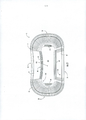
[0008] A Figura 1 é uma vista plana de uma blanqueta usada para a formação de um recipiente de acordo com uma primeira modalidade da divulgação.[0008] Figure 1 is a plan view of a blanket used for forming a container according to a first embodiment of the disclosure.
[0009] A Figura IA é uma vista em corte transversal parcial de uma porção marginal da blanqueta da Figura 1.[0009] Figure 1A is a partial cross-sectional view of a marginal portion of the blanket of Figure 1.
[0010] A Figura 1B é uma vista em corte transversal parcial de uma área de canto inferior da blanqueta da Figura 1.[0010] Figure 1B is a partial cross-sectional view of a lower corner area of the blanket of Figure 1.
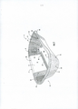
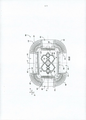
[0011] A Figura 2 é uma vista em perspectiva do recipiente formado a partir da blanqueta da Figura 1 de acordo com a primeira modalidade da divulgação.[0011] Figure 2 is a perspective view of the container formed from the blanket of Figure 1 according to the first embodiment of the disclosure.
[0012] A Figura 3 é uma vista superior em perspectiva dorecipiente da Figura 2.[0012] Figure 3 is a top perspective view of the container of Figure 2.
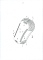
[0013] A Figura 4 é uma vista em perspectiva inferior dorecipiente da Figura 2.[0013] Figure 4 is a bottom perspective view of the container of Figure 2.
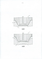
[0014] As Figuras 5A e 5B são vistas esquemáticas de umaferramenta de conformação exemplar para a formação de um recipiente de acordo com uma modalidade representativa.[0014] Figures 5A and 5B are schematic views of an exemplary shaping tool for forming a container according to a representative embodiment.
[0015] A Figura 6 é uma vista plana de uma blanqueta usada para a formação de um recipiente de acordo com uma segunda modalidade da divulgação.[0015] Figure 6 is a plan view of a blanket used for forming a container according to a second embodiment of the disclosure.
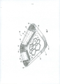
[0016] A Figura 7 é uma vista em perspectiva do recipiente formado a partir da blanqueta da Figura 6 de acordo com a segunda modalidade da divulgação.[0016] Figure 7 is a perspective view of the container formed from the blanket of Figure 6 according to the second embodiment of the disclosure.
[0017] A Figura 8 é uma vista superior em perspectiva dorecipiente da Figura 7.[0017] Figure 8 is a top perspective view of the container of Figure 7.
[0018] A Figura 9 é uma vista em perspectiva inferior dorecipiente da Figura 7.[0018] Figure 9 is a bottom perspective view of the container of Figure 7.
[0019] As partes correspondentes são designadas por números de referência correspondentes em todos os desenhos.[0019] Corresponding parts are designated by corresponding reference numbers throughout the drawings.
[0020] A presente invenção refere-se genericamente a vários aspectos de receptores, construtos, bandejas, materiais, embalagens, elementos e artigos, e a métodos de fazer tais recipientes, construtos, bandejas, materiais, embalagens, elementos e artigos. Embora vários aspectos diferentes, implementações e modalidades sejam revelados, as numerosas inter-relações entre suas combinações e modificações dos vários aspectos, as implementações e modalidades são aqui contempladas. Numa modalidade ilustrada, a presente descrição refere-se a formar um recipiente ou bandeja para acondicionar alimentos ou outros artigos. No entanto, em outras modalidades, o recipiente de bandeja ou pode ser usado para formar outros artigos de contenção para não alimentos, ou podem ser usados para aquecimento ou cozimento.The present invention relates generally to various aspects of receivers, constructs, trays, materials, packages, elements and articles, and to methods of making such containers, constructs, trays, materials, packages, elements and articles. Although several different aspects, implementations and modalities are disclosed, the numerous interrelationships between their combinations and modifications of the various aspects, implementations and modalities are contemplated here. In an illustrated embodiment, the present description relates to forming a container or tray for storing food or other items. However, in other embodiments, the tray container can either be used to form other non-food containment items, or can be used for heating or cooking.
[0021] A Figura 1 ilustra uma estrutura 3 que é utilizada para formar um recipiente 5 (Figuras 2-4) que tem um flange 7 de acordo com uma primeira modalidade da divulgação. Na modalidade ilustrada, a blanqueta 3 tem bordas laterais geralmente retas e bordas terminais semicirculares ou em forma de arco. A blanqueta 3 é para ser transformada por prensagem no recipiente 5 que, na modalidade ilustrada, é uma bandeja com um lado geralmente reto, um lado côncavo, e extremidades convexas. Deve ser entendido que a blanqueta 3 pode ser transformada por prensagem no recipiente 5 através de uma ferramenta de formação T (mostrada esquematicamente nas Figuras 5A e 5B, a titulo de exemplo), que podem ser similares e terem características e/ou componentes similares como as das ferramentas convencionais de formação, tais como aquelas que são reveladas na Publicação do Pedido de Patente norte- americano US No. 2005/0109653, todo o conteúdo da qual fica aqui incorporado por referência para todos os fins. Também, a ferramenta de conformação pode ter características e componentes semelhantes, tal como das ferramentas de conformação revelados no Pedido Internacional No. WO 2008/049048, todo o conteúdo do qual aqui se incorpora por referência para todos os fins, ou qualquer outro conjunto de ferramenta de formação adequado. Além disso, a blanqueta 3 e o recipiente 5 podem ser moldados de formas alternativas (por exemplo, circular, oval, retangular, irregular, etc.), sem nos afastarmos do escopo da presente divulgação. A blanqueta 3 da presente revelação tem características que ajudam a reduzir, prevenir ou eliminar a delaminação e/ou o abaulamento de um material de laminação num interior do recipiente 5 produzido a partir da blanqueta numa área de canto inferior 9 do recipiente.[0021] Figure 1 illustrates a structure 3 that is used to form a container 5 (Figures 2-4) having a flange 7 according to a first embodiment of the disclosure. In the illustrated embodiment, blanket 3 has generally straight side edges and semicircular or arc-shaped end edges. Blanket 3 is to be formed by pressing into container 5 which, in the illustrated embodiment, is a tray with a generally straight side, a concave side, and convex ends. It should be understood that blanket 3 can be formed by pressing into container 5 through a T-forming tool (shown schematically in Figures 5A and 5B, by way of example), which may be similar and have similar characteristics and/or components as those of conventional training tools, such as those disclosed in U.S. Patent Application Publication No. 2005/0109653, the entire contents of which are incorporated herein by reference for all purposes. Also, the forming tool may have similar features and components as those of the forming tools disclosed in International Application No. WO 2008/049048, the entire contents of which are incorporated herein by reference for all purposes, or any other set of Appropriate training tool. Furthermore, blanket 3 and container 5 may be molded in alternative shapes (e.g. circular, oval, rectangular, irregular, etc.) without departing from the scope of the present disclosure. The blanket 3 of the present disclosure has features that help to reduce, prevent or eliminate delamination and/or bulging of a laminating material in an interior of the container 5 produced from the blanket in a lower corner area 9 of the container.
[0022] A blanqueta 3 pode ser transformada a partir de um material laminado que inclui mais de uma camada, mas alternativamente, o laminado pode ser substituído com uma única camada de material, tal como, mas não limitado a, cartão, papelão, papel, ou uma folha polimérica. De acordo com as modalidades representativas da presente invenção, o laminado pode incluir uma camada de laminação 8, que pode ser uma camada interativa com micro-ondas tal como é comum em recipientes MicroRite® disponíveis da Graphic Packaging Internacional of Marietta, GA. A camada de laminação pode ser geralmente referida como tal, ou pode ter, como um dos seus componentes, uma folha, uma blindagem de micro-ondas, ou qualquer outro termo ou componente que se refere a uma camada de material apropriado para blindagem da energia de microondas e/ou para induzir o aquecimento num forno de microondas. Alternativamente, a camada de laminação 8 pode ser qualquer material adequado que é laminada sobre um substrato. A camada de laminação 8 compreende a superfície externa/exterior 12 da blanqueta 3 (Figuras 1 e IA) . Na modalidade ilustrada, a blanqueta 3 tem um substrato ou camada base 14 formando uma superfície externa/exterior 16 (Figura IA) da blanqueta 3. A camada de laminação 8 é suportado por, e fixada a (por exemplo, laminada por sobre), a camada base 14, que pode ser na forma de um papelão, cartão, polimero ou qualquer outro material adequado. No entanto e de acordo com as modalidades exemplares, a camada base 14 é, tipicamente, um cartão não revestido. A camada de laminação 8 pode ser constituída de outros materiais interativos de micro-ondas adequados definidos abaixo, ou por qualquer outro material adequado.[0022] Blanket 3 can be made from a laminated material that includes more than one layer, but alternatively, the laminate can be replaced with a single layer of material such as, but not limited to, cardboard, cardboard, paper , or a polymeric sheet. In accordance with representative embodiments of the present invention, the laminate may include a lamination layer 8, which may be a microwave interactive layer as is common in MicroRite® containers available from Graphic Packaging International of Marietta, GA. The lamination layer may be generally referred to as such, or may have, as one of its components, a sheet, a microwave shield, or any other term or component that refers to a layer of material suitable for energy shielding. microwave oven and/or to induce heating in a microwave oven. Alternatively, lamination layer 8 can be any suitable material that is laminated onto a substrate. The lamination layer 8 comprises the outer/
[0023] Como mostrado na Figura 1, a blanqueta 3 tem uma direção longitudinal LI e uma direção longitudinal L2, em que uma linha central CL longitudinal da blanqueta 3 é geralmente paralela ao sentido longitudinal Ll, e um TC de eixo transversal da blanqueta é geralmente paralela ao sentido lateral L2 . A blanqueta 3 tem uma porção central 11, uma borda externa 13, e uma porção marginal 15 entre a borda externa 13 e a porção central 11. Tal como mostrado na Figura 1, a área de canto inferior 9 forma uma área de transição entre a parte inferior 11 e a porção marginal 15. Adicionalmente, a blanqueta 3 pode incluir uma primeira região lateral 21, uma segunda região lateral 23, e duas regiões terminais 25.[0023] As shown in Figure 1, blanket 3 has a longitudinal direction LI and a longitudinal direction L2, wherein a longitudinal centerline CL of blanket 3 is generally parallel to the longitudinal direction Ll, and a TC of the blanket's transverse axis is usually parallel to the lateral direction L2 . Blanket 3 has a
[0024] Numa modalidade, a porção marginal 15 da blanqueta 3 compreende uma pluralidade de linhas de vinco 19. As linhas de vinco 19 estão todas posicionadas na porção marginal 15 nas regiões terminais 25 de modo a que as linhas de vinco se prolongam geralmente no sentido radial a partir da borda externa 13 da blanqueta. Numa modalidade, linhas de vinco adjacentes 19 nas respectivas regiões curvas 27 (por exemplo, onde a borda externa 13 é geralmente curva) podem ser espaçadas por um ângulo Al de, pelo menos, cerca de 5 graus.[0024] In one embodiment, the marginal portion 15 of blanket 3 comprises a plurality of
[0025] Alternativamente, o ângulo Al pode ser qualquer ângulo adequado. Nas respectivas porções retas 29 (por exemplo, onde a borda externa 13 é de forma geral reta), as linhas de vinco 19 são geralmente paralelas. Numa modalidade, as linhas de vinco 19 se estendem até a borda externa 13 da blanqueta 3, mas as linhas de vinco podem ter um ponto terminal radialmente externo que fica afastado da borda externa da blanqueta sem se afastar da revelação. Além disso, numa modalidade, as linhas de vinco 19 se formam na superfície interna 12 tal que as linhas de vinco 19 compreendem endentações leves na superfície interna 12 da blanqueta sobre a superfície da camada de laminação 8 e ligeiras saliências sobre a superfície externa 16 da blanqueta sobre a superfície externa da camada base 14. As linhas de vinco 19 podem ser omitidas ou podem ser de outras formas modeladas, dispostas e/ou configuradas sem nos afastarmos da divulgação.[0025] Alternatively, angle Al can be any suitable angle. In the respective straight portions 29 (eg where the outer edge 13 is generally straight), the crease lines 19 are generally parallel. In one embodiment, the crease lines 19 extend to the outer edge 13 of the blanket 3, but the crease lines may have a radially outer end point that is spaced from the outer edge of the blanket without departing from the disclosure. Furthermore, in one embodiment, the crease lines 19 are formed on the
[0026] Na modalidade ilustrada, uma pluralidade de linhas de vinco 30 pode ser inclusa na área de canto inferior 9 da blanqueta 3 para ajudar a reduzir a delaminação da camada de laminação 8 a partir da camada base 14. A pluralidade de linhas de vinco 30 pode incluir linhas de vinco laterais primárias 33 se estendendo adjacentes à primeira região lateral 21, linhas de vinco laterais secundárias 35 se estendendo adjacentes à segunda região lateral 23, e linhas de vinco terminais 37 que se prolongam adjacentes a cada uma das regiões terminais 25. Numa modalidade, como esquematicamente mostrado na Figura IB, as linhas de vinco 30 se formam na superficie interna 12, de modo que as linhas de vinco 30 compreendem ligeiras endentações, fendas ou sulcos na superficie interna 12 da blanqueta e ligeiras saliências na superficie externa 16 da blanqueta. Na modalidade ilustrada, as linhas de vinco laterais primárias 33 são geralmente retas e geralmente paralelas à linha central longitudinal CL, e as linhas de vinco terminais 37 são geralmente retas e geralmente paralelas à linha central transversal CT. Como mostrado na Figura 1, as linhas de vinco laterais secundárias 35 são curvas, tal que as respectivas extremidades das linhas de vinco individuais ficam mais afastada da linha central longitudinal CL e da primeira região lateral 21 que dos respectivos pontos intermediários das linhas de vinco. As primeira e segunda linhas de vinco laterais 33, 35 podem ser geralmente centradas sobre a linha central transversal CT, e as linhas de vinco terminais 37 podem ser geralmente centradas sobre a linha central longitudinal CL. As linhas de vinco 30 podem ser omitidas ou podem ser configuradas, dispostas e/ou configuradas de outros modos, sem nos afastarmos da divulgação.[0026] In the illustrated embodiment, a plurality of
[0027] Num exemplo, a camada base de papelão 14 da blanqueta 3 pode compreender papelão 18 pontos possuindo espessura de aproximadamente 0,46 mm (0,018 polegada), e a camada de laminação 8 pode ter uma espessura de aproximadamente 0,025 mm (0,001 polegada) tal que a blanqueta 3 tem uma espessura total Tb de aproximadamente 0,48 mm (0,019 polegada). A espessura de uma folha contida na camada de laminação 8 pode ser de aproximadamente 0,007 mm (0,000275 polegadas), por exemplo. Numa modalidade, a espessura da camada base de papelão 14 pode estar na faixa de aproximadamente 0,33 mm (0,013 polegadas) a aproximadamente 0,72 mm (0,030 polegadas), a espessura da camada de laminação 8 pode estar na faixa de aproximadamente 0,013 mm (0,0005 polegada) a aproximadamente 0,038 mm (0,0015 polegada), e a espessura total Tb pode estar na faixa de 0,34 mm (0,0135 polegada) a aproximadamente 0,80 mm (0,0315 polegada). Qualquer das espessuras acima indicadas ou outras dimensões indicadas acima podem ser maiores ou menores que as indicadas ou podem estar dentro ou fora das faixas, sem se afastar do escopo da divulgação. Toda a informação dimensional aqui apresentada destina-se a ser ilustrativa de certos aspectos da descrição e não se destina a limitar o âmbito da revelação, uma vez que diversas outras modalidades da revelação podem incluir dimensões que sejam maiores ou menores que as dimensões aqui mencionadas.[0027] In one example, the
[0028] As Figuras 2-4 mostram uma modalidade da divulgação que compreende um recipiente 5 formado a partir da blanqueta 3. O recipiente 5 compreende uma parede inferior geralmente em elevação 133, um canto inferior 135 que conecta a parede de fundo a uma parede lateral 137, um canto superior 139 que conecta a parede lateral 137 com o flange 7, e uma borda externa 141. A parede de fundo 133 é geralmente formada a partir da porção de fundo 11 da blanqueta 3, o canto inferior 135 é geralmente formado a partir da área de canto inferior 9 da blanqueta , e a parede lateral 137 e o flange 7 se formam a partir da porção marginal 15 da blanqueta. A extremidade radial exterior 141 geralmente pode corresponder ao bordo exterior 13 da blanqueta 3. A parede lateral 133 e a parede inferior 137 definem pelo menos parcialmente um espaço ou cavidade interna 145 do recipiente 5. A camada de laminação 8 fica na superficie interna/interior 12 do recipiente 5, e a camada base 14 fica na superficie externa/externa 16 do recipiente. O recipiente 5 é para acondicionar e/ou cozinhar e/ou aquecer um produto alimenticio (não mostrado) que é colocado no espaço interno 145 do recipiente.[0028] Figures 2-4 show an embodiment of the disclosure comprising a container 5 formed from blanket 3. Container 5 comprises a generally in elevation
[0029] Tal como mostrado nas Figuras 2-4, o flange se estende para fora a partir da parede lateral 137, e um canto superior inclinado 139 do flange 7 pode ser obliquo relativamente à parede lateral 137 e o restante do flange 7. Alternativamente, o canto superior 139 pode ser curvo ou formado de outro modo ou omitido. Na modalidade ilustrada, a parede lateral 137 se prolonga geralmente para cima a partir do canto inferior 135 e da parede de fundo 133, e o canto inferior 135 é encurvado tal que a porção mais inferior do recipiente 5 fica situada ao longo da curva do canto inferior 135. Por conseguinte, quando o recipiente 5 é colocado na posição vertical sobre uma superficie, uma porção de canto inferior 135 repousa na superficie e a parede inferior 133 fica afastada da superficie.[0029] As shown in Figures 2-4, the flange extends outward from the
[0030] Tal como mostrado nas Figuras 2 e 3, a parede lateral 137, o flange 7, e o canto inferior 135 incluem a primeira região lateral 21, em que a parede lateral 137 e a borda externa 141 ficam geralmente retas, a segunda região lateral 23, em que a parede lateral 137 e a borda externa 141 são encurvadas para o interior 145 do recipiente 5 (por exemplo, côncavas), e as regiões terminais 25 em que a parede lateral 137 e a borda externa 141 formam porções convexas conectadas por uma porção geralmente reta. 0 recipiente 5 pode ter outras formas e/ou dimensões, sem se afastar da divulgação.[0030] As shown in Figures 2 and 3, the
[0031] Na modalidade ilustrada, quando a blanqueta 3 é transformada no recipiente 5, as linhas de vinco 19 formam porções ou pregas sobrepostas 31. Na modalidade ilustrada, as porções sobrepostas 31 estão no flange 7 do recipiente e na parede lateral 137, e se estendem para baixo na parede lateral até uma localização adjacente da parede de fundo 133. As partes sobrepostas 31 podem ser modeladas, dispostas e/ou configuradas de outros modos, sem se afastar da presente invenção.[0031] In the illustrated embodiment, when blanket 3 is transformed into container 5, the crease lines 19 form overlapping portions or folds 31. In the illustrated embodiment, overlapping
[0032] Como mostrado na Figura 3, a pluralidade de linhas de vinco 30 fica geralmente disposta no canto inferior 135 e podem ajudar a evitar que a camada de laminação 8 se separe da camada base 14 e se estendem ao interior 145 do recipiente 5. As linhas primárias de vincagem lateral 33 são geralmente retas de modo a corresponderem com a primeira região lateral 21 geralmente reta da parede lateral 137, as linhas secundárias de vincagem lateral 35 são encurvadas de modo a corresponderem com a segunda região lateral côncava 23 da parede lateral, e as linhas de vincagem terminais 37 são geralmente retas de modo a corresponderem às porções geralmente retas das regiões terminais 25 da parede lateral. Numa modalidade alternativa, os vincos terminais 37 podem ser encurvados com as porções curvas das regiões terminais.[0032] As shown in Figure 3, the plurality of
[0033] Numa modalidade, a camada de laminação 8 pode ser geralmente mais resistente à compressão - especialmente em comparação com a camada base de papelão 14. Uma vez que a camada de laminação 8 é interna à camada base 14, o material da camada de laminação 8 pode amontoar ou entortar no canto inferior 135 e se separar da camada base 14. Por exemplo, as interações de microcamadas entre a camada de laminação e a camada base podem induzir a um adesivo que fixa as camadas juntas a falhar onde o adesivo for mais fraco e/ou ausente (por exemplo, devido a uma aplicação desigual). Se os vincos 30 são omitidos, o material da camada de laminação 8 pode se separar da camada base 14 e se estender para o interior 145 do recipiente 5. As porções separadas da camada de laminação podem ser danificadas por um utensilio de alimentação, por exemplo, e podem se rasgar da superficie interna 12 e se misturar com o item alimentício contido no recipiente 5. Embora os materiais usados na camada de laminação 8 sejam tipicamente inertes, os danos na superficie interna do recipiente 5 podem reduzir o apelo visual do recipiente e dos itens de alimento (ou outros itens) ali contidos. Adicionalmente, as peças de laminação soltas podem causar preocupações e/ou influenciar o gozo de um alimento (ou outro item) no recipiente, por parte do consumidor.[0033] In one embodiment, the lamination layer 8 may generally be more resistant to compression - especially compared to the
[0034] Os vincos 30 podem ajudar a impedir que a camada de laminação 8 se agrupe no interior 145. Como mostrado esquematicamente na Figura 1B, os vincos 30 formam geralmente sulcos na superficie interna 12 do recipiente tal que a camada de laminação 8 fica um tanto estirada no canto inferior 135. Por conseguinte, a camada de laminação é comprimida para dentro dos sulcos dos vincos 30 quando a blanqueta é pressionada na forma do recipiente, e a camada de laminação fica menos passivel de delaminar da camada base 14. Porções da camada de laminação que podem separar da camada base ficarão ainda dispostas dentro dos sulcos dos vincos 30, e, portanto, serão comprimidas para dentro da curva do canto inferior e pelo menos parcialmente protegidas contra os utensílios de comer, por exemplo, pelos sulcos. Por conseguinte, quaisquer porções delaminadas da camada de laminação 8 ficará menos passivel de se desprender do recipiente e se misturar com o item alimenticio (ou outro item) no recipiente. Por conseguinte, a delaminação da camada de laminação 8 é reduzida e controlada de modo a ajudar a manter o apelo visual e a segurança do recipiente e do alimento ou de outros artigos contidos no recipiente.The
[0035] Numa modalidade, a blanqueta 3 é transformada no recipiente mediante conduzir a blanqueta e colocar a blanqueta na ferramenta de formação T (esquematicamente mostrado nas Figuras 5A e 5B, a titulo de exemplo) com uma ferramenta de montagem inferior L e montagem de ferramenta superior U numa posição separada ou aberta. A ferramenta de formação T é usada para transformar por prensagem a blanqueta 3 no recipiente 5, mediante movimentar as montagens de ferramentas L, U, juntas, para uma posição fechada (Figura 5A, por exemplo). Após formação por prensagem do recipiente 5, as montagens de ferramentas L, U podem ser separadas (Figura 5, por exemplo) para liberar o recipiente 5. Quando a blanqueta plana 3 é prensada na ferramenta de formação T, o substrato 14 e a camada de laminação 8 são comprimidos e transformados no recipiente tridimensional 5. As linhas de vinco 19 facilitam a transformação da blanqueta plana no recipiente tridimensional na ferramenta de transformação, e as linhas de vinco 30 ajudam a prevenir ou a reduzir o empenamento da camada de laminação. As linhas de vinco 19 permitem a transformação da porção marginal 15 da blanqueta 3 na parede lateral 137 e flange 7 do recipiente 5. O recipiente 5 pode ser formado de outros modos e/ou pode ser formado por meio de qualquer ferramenta ou ferramentas de formação adequadas, sem se afastar da revelação. A ferramenta de formação T mostrada esquematicamente nas Figuras 5A e 5B está inclusa apenas a titulo de exemplo.[0035] In one embodiment, the blanket 3 is transformed into the container by driving the blanket and placing the blanket in the forming tool T (schematically shown in Figures 5A and 5B, by way of example) with a lower assembly tool L and assembly of upper tool U in a separate or open position. The forming tool T is used to press blanket 3 into container 5 by moving the tool assemblies L, U, together, to a closed position (Figure 5A, for example). After press forming the container 5, the tool assemblies L, U can be separated (Figure 5, for example) to release the container 5. When the flat blanket 3 is pressed into the forming tool T, the
[0036] A Figura 6 é uma vista de uma superficie interna 412 de uma blanqueta 403 para formar um recipiente 405 (Figuras 7- 9) de acordo com uma segunda modalidade da divulgação. A segunda modalidade é genericamente semelhante àquela da primeira modalidade, com exceção das variações observadas e variações que serão evidentes para aquele usualmente versado na técnica. Por conseguinte, as características similares ou idênticas das modalidades foram dadas como ou números de referência semelhantes. Como mostrado na Figura 6, a blanqueta 403 é geralmente retangular com duas zonas laterais 421 e duas regiões terminais 425. A blanqueta 403 tem uma porção central 411, uma borda externa 413, uma porção marginal 415, e uma área de canto inferior 409. Uma pluralidade de linhas de vinco 419 se posiciona na porção marginal 415 nos respectivos cantos curvos 427 para a formação de pregas 431 (Figura 7). Uma pluralidade de linhas de vinco 430 na área de canto 409 pode ser geralmente semelhante às linhas de vinco 30 da modalidade anterior. As linhas de vinco 430 incluem geralmente linhas laterais de vinco geralmente retas 433 e linhas de vinco terminais 437. Como mostrado na Figura 6, a folha da camada de laminação 408 fica disposta num padrão particular 418. Em alternativa, a folha pode ser distribuída em qualquer padrão apropriado na camada de laminação, pode ser uniformemente distribuída na camada de laminação, ou pode ser omitida. Como mostrado nas Figuras 7-9, o recipiente 405 inclui uma parede inferior geralmente em elevação 533, um canto inferior 535 com a pluralidade de vincos 430, uma parede lateral 537, e um flange 407. O recipiente 405 inclui também regiões laterais geralmente retas 421, regiões terminais geralmente retas 425, e os cantos curvos 438. A blanqueta 403 e/ou o recipiente 405 pode ser de outra forma moldados, dispostos e/ou configurados, sem se afastar da divulgação.[0036] Figure 6 is a view of an
[0037] Qualquer uma das características das várias modalidades da presente descrição pode ser combinada com, substituída por, ou de outra forma configurada com outras características das outras modalidades da presente descrição sem se afastar do âmbito desta divulgação.[0037] Any of the features of the various embodiments of the present description may be combined with, replaced by, or otherwise configured with other features of the other embodiments of the present description without departing from the scope of this disclosure.
[0038] Opcionalmente, uma ou mais porções da blanqueta ou outros construtos aqui descritos ou contemplados, podem ser revestidos com verniz, substância argilosa ou outros materiais, seja individualmente ou em combinação. O revestimento pode ser em seguida impresso sobre com propaganda do produto ou outra informação ou imagens. As blanquetas ou outros construtos podem ser também seletivamente revestidos e/ou impressos tal que menos que uma área superficial completa da blanqueta ou substancialmente a área superficie completa da blanqueta possa ser revestida e/ou impressa.[0038] Optionally, one or more portions of the blanket or other constructs described or contemplated herein, may be coated with varnish, clayey substance or other materials, either individually or in combination. The coating can then be printed over with product advertising or other information or images. The blankets or other constructs can also be selectively coated and/or printed such that less than a complete surface area of the blanket or substantially the entire surface area of the blanket can be coated and/or printed.
[0039] Além disso, os recipientes 5, 405 podem cooperar com uma tampa (não mostrada) para acondicionar, aquecer e/ou cozinhar um produto alimentar ou outro item que esteja contido no recipiente, sem nos afastarmos da divulgação.[0039] In addition,
[0040] Qualquer das blanquetas, recipientes, ou outros construtos da presente divulgação podem opcionalmente incluir uma ou mais características que alterem o efeito da energia de micro-ondas durante o aquecimento ou o cozimento de um produto alimentar que esteja associado com a bandeja ou a outro construto. Por exemplo, a blanqueta, bandeja, recipiente ou outro construto pode ser formado pelo menos parcialmente a partir de um ou mais elementos interativos com a energia de micro-ondas (a seguir por vezes referido como "elementos interativos de micro-ondas") que promovem o aquecimento, tostagem e/ou gratinagem de um área particular do artigo alimentar, protegem uma área particular do artigo alimentar da energia de micro-ondas para evitar cozimento excessivo do mesmo, ou transmitem energia de micro-ondas na direção ou em afastamento de uma área particular do item alimentício. Cada elemento interativo com o micro-ondas compreende um ou mais materiais interativos com a energia do micro-ondas ou segmentos dispostos numa configuração particular para absorver a energia de micro-ondas, transmitir a energia de micro-ondas, refletir a energia de micro-ondas, ou direcionar a energia de micro-ondas, de acordo com o necessário ou desejado, para um particular construto e item alimentício.[0040] Any of the blankets, containers, or other constructs of the present disclosure may optionally include one or more features that alter the effect of microwave energy during heating or cooking of a food product that is associated with the tray or the another construct. For example, the blanket, tray, container or other construct may be formed at least partially from one or more elements interacting with microwave energy (hereinafter sometimes referred to as "interactive microwave elements") that promote heating, toasting and/or browning of a particular area of the food item, protect a particular area of the food item from microwave energy to prevent over-cooking the same, or transmit microwave energy towards or away from a particular area of the food item. Each microwave interactive element comprises one or more microwave energy interactive materials or segments arranged in a particular configuration to absorb microwave energy, transmit microwave energy, reflect microwave energy. waves, or directing microwave energy, as needed or desired, to a particular construct and food item.
[0041] No caso de um susceptor ou blindagem, o material interativo com a energia de micro-ondas pode compreender um material condutor elétrico ou um material semicondutor, por exemplo, um metal ou liga metálica depositada em condições de vácuo, ou uma tinta metálica, uma tinta orgânica, uma tinta inorgânica, uma pasta metálica, uma pasta orgânica, uma pasta inorgânica, ou qualquer combinação dos mesmos. Exemplos de metais e ligas metálicas que podem ser adequadas incluem, mas não estão limitadas a, aluminio, cromo, cobre, ligas de inconel (liga de niquel-cromo-molibdênio com nióbio), ferro, magnésio, níquel, aço inox, estanho, titânio, tungsténio, e qualquer combinação ou liga dos mesmos.[0041] In the case of a susceptor or shield, the microwave energy-interactive material may comprise an electrically conductive material or a semiconductor material, for example, a metal or metallic alloy deposited under vacuum conditions, or a metallic paint , an organic paint, an inorganic paint, a metallic paste, an organic paste, an inorganic paste, or any combination thereof. Examples of metals and metal alloys that may be suitable include, but are not limited to, aluminum, chromium, copper, inconel alloys (nickel-chromium-molybdenum alloy with niobium), iron, magnesium, nickel, stainless steel, tin, titanium, tungsten, and any combination or alloy thereof.
[0042] Alternativamente, o material interativo com a energia de micro-ondas pode compreender um óxido metálico, por exemplo, óxidos de aluminio, ferro e estanho, opcionalmente usados em conjunto com um material eletricamente condutor. Outro óxido metálico que pode ser apropriado é o óxido de indio e estanho (ITO). 0 ITO tem uma estrutura cristalina mais uniforme e, portanto, é claro na maioria das espessuras de revestimento.[0042] Alternatively, the microwave energy interactive material may comprise a metal oxide, for example, oxides of aluminum, iron and tin, optionally used in conjunction with an electrically conductive material. Another metal oxide that may be suitable is indium tin oxide (ITO). ITO has a more uniform crystal structure and is therefore clear in most coating thicknesses.
[0043] Alternativamente, o material interativo com a energia de micro-ondas pode compreender um adequado eletrocondutor, semicondutor ou dielétrico ou ferroelétrico artificial não condutor. Dielétricos artificiais compreende material condutor, subdividido na forma de uma matriz polimérica ou outra matriz ou aglutinante, e podem incluir escamas de um metal eletrocondutor, por exemplo, aluminio.[0043] Alternatively, the microwave energy interactive material may comprise a suitable electroconductor, semiconductor or dielectric or non-conductive artificial ferroelectric. Artificial dielectrics comprise conductive material, subdivided in the form of a polymeric matrix or other matrix or binder, and may include flakes of an electroconductive metal, e.g., aluminum.
[0044] Em outras modalidades, o material interativo com a energia de micro-ondas pode ser à base de carbono, por exemplo, como divulgado nas Patentes norte-americanas US Nos. 4.943.456, 5.002.826, 5.118.747, e 5.410.135.[0044] In other embodiments, the microwave energy-interactive material may be carbon-based, for example, as disclosed in US Pat. 4,943,456, 5,002,826, 5,118,747, and 5,410.135.
[0045] Ainda em outras modalidades, o material interativo com a energia de micro-ondas pode interagir com a porção eletromagnética no foro de micro-ondas. Materiais corretamente selecionados para esse tipo podem ser auto-limitantes com base na perda da interação quando a temperatura Curie do material é alcançada. Um exemplo de tal revestimento interativo está descrito na Patente norte-americanas U.S. No. 4.283.427.[0045] Still in other modalities, the material interacting with microwave energy can interact with the electromagnetic portion in the microwave forum. Materials correctly selected for this type can be self-limiting based on the loss of interaction when the material's Curie temperature is reached. An example of such an interactive coating is described in U.S. Patent No. 4,283,427.
[0046] O uso de outros elementos interativos com a energia de micro-ondas é também contemplado. Em um exemplo, o elemento interativo com a energia de micro-ondas pode compreender uma folha metálica ou material evaporado de alta densidade óptica, possuindo uma espessura suficiente para refletir uma porção substancial da energia de micro-ondas colidente. Tais elementos são tipicamente formados a partir de um metal ou liga metálica refletiva, condutora, por exemplo, de aluminio, cobre, ou de aço inox, na forma de um "remendo" possuindo geralmente uma espessura de a partir de cerca de 0,0072 mm (0,000285 polegada), até cerca de 0,005 polegada, por exemplo, de a partir de cerca de 0,0076 mm (0,0003 polegada) até cerca de 0,0762 mm (0,003 polegada). Outros elementos como tais podem ter uma espessura de a partir de cerca de 0,00035 polegada até cerca de 0,002 polegada, por exemplo, de 0,0406 mm (0,0016 polegada).[0046] The use of other elements interactive with microwave energy is also contemplated. In one example, the microwave energy interactive element may comprise a metallic sheet or evaporated material of high optical density, having a thickness sufficient to reflect a substantial portion of the impinging microwave energy. Such elements are typically formed from a conductive, reflective metal or metal alloy, for example, aluminium, copper, or stainless steel, in the form of a "patch" generally having a thickness of from about 0.0072 mm (0.000285 inches), to about 0.005 inches, for example, from about 0.0076 mm (0.0003 inches) to about 0.0762 mm (0.003 inches). Other elements as such may have a thickness of from about 0.00035 inches to about 0.002 inches, for example 0.0406 mm (0.0016 inches).
[0047] Em alguns casos, elementos refletivos da energia de micro-ondas (ou reflexivos) podem ser usados como elementos de blindagem onde o item alimentício é tendente a chamuscar ou secar durante o aquecimento. Em outros casos, elementos que refletem a energia de micro-ondas podem ser usados para difundir ou reduzir a intensidade da energia de micro-ondas. Um exemplo de tal material que utiliza tais elementos refletivos da energia de micro-ondas é comercialmente disponível da Graphic Packaging International, Inc. (Marietta, GA) com o nome comercial de material de embalagem MicroRite®. Em outros exemplos, uma pluralidade de elementos que refletem a energia de micro-ondas pode ser disposta de modo a formar um elemento de distribuição de energia de micro-ondas para direcionar a energia de micro-ondas para áreas especificas do produto alimentar. Se desejado, as alças podem ser de um comprimento que faça com que a energia de micro-ondas entre em ressonância, reforçando assim o efeito de distribuição. Os elementos que distribuem a energia de micro-ondas são descritos nas Patentes norte-americanas U.S. Nos. 6.204.492, 6.433.322, 6.552.315, e 6.677.563, cada uma das quais aqui se incorpora por referência nas suas totalidades.[0047] In some cases, microwave energy reflective (or reflective) elements may be used as shielding elements where the food item is prone to scorch or dry out during heating. In other cases, elements that reflect microwave energy can be used to diffuse or reduce the intensity of microwave energy. An example of such material that utilizes such microwave energy reflective elements is commercially available from Graphic Packaging International, Inc. (Marietta, GA) under the trade name MicroRite® packaging material. In other examples, a plurality of microwave energy reflecting elements may be arranged to form a microwave energy distribution element to direct microwave energy to specific areas of the food product. If desired, the loops can be of a length that causes the microwave energy to resonate, thus enhancing the distribution effect. Elements that distribute microwave energy are described in U.S. Patent Nos. 6,204,492, 6,433,322, 6,552,315, and 6,677,563, each of which is incorporated herein by reference in their entirety.
[0048] Se desejado, qualquer um dos numerosos elementos interativos com a energia de micro-ondas aqui descritos ou aqui contemplados pode ser substancialmente continuo, isto é, sem intervalos ou interrupções substanciais, ou pode ser descontinuo, por exemplo, através da inclusão de um ou mais intervalos ou aberturas que transmitam energia de micro-ondas. Os intervalos ou aberturas podem se estender através de toda a estrutura, ou apenas através de uma ou mais camadas. A quantidade, forma, tamanho e o posicionamento de tais intervalos ou aberturas podem variar quanto a uma aplicação particular, dependendo to tipo de construto que estiver sendo formado, do item alimentício a ser aquecido em seu interior ou sobre ele, do grau desejado de aquecimento, tostagem e/ou crocância, caso seja necessária exposição direta ao microondas ou se for desejado de modo a alcançar aquecimento uniforme do item alimentício, da necessidade quanto à regulagem da alteração na temperatura do item alimentício através do aquecimento direto, e também ao nivel que seja necessário quanto a uma ventilação.[0048] If desired, any of the numerous microwave energy interacting elements described or contemplated herein may be substantially continuous, that is, without substantial gaps or interruptions, or may be discontinuous, for example, through the inclusion of one or more gaps or openings that transmit microwave energy. Gaps or openings can extend through the entire structure, or just through one or more layers. The quantity, shape, size and placement of such gaps or openings may vary for a particular application, depending on the type of construct being formed, the food item being heated in or over it, the desired degree of heating , toasting and/or crispness, if direct exposure to microwaves is necessary or if desired in order to achieve uniform heating of the food item, the need for regulation of the change in temperature of the food item through direct heating, and also at the level that is necessary for ventilation.
[0049] A titulo de ilustração, um elemento interativo com a energia de micro-ondas pode incluir uma ou mais zonas transparentes para efetuar o aquecimento dielétrico do item alimentar. No entanto, quando o elemento interativo com a energia de micro-ondas compreende um susceptor, tais aberturas diminuem a área total interativa da energia de micro-ondas e, portanto, diminuem a quantidade de material interativo com a energia de micro-ondas disponível para o aquecimento, tostagem, e/ou crocância da superfície do produto alimentar. Assim, as quantidades relativas as áreas interativas com a energia de micro-ondas e das áreas transparentes relativamente à energia de micro-ondas podem ser equilibradas para alcançar as desejadas características gerais de aquecimento para o produto alimentar particular.[0049] By way of illustration, an element interactive with microwave energy may include one or more transparent zones to effect dielectric heating of the food item. However, when the microwave energy interactive element comprises a susceptor, such openings decrease the total microwave energy interactive area and therefore decrease the amount of microwave energy interactive material available to the heating, browning, and/or crispness of the surface of the food product. Thus, the amounts relative to the microwave energy interacting areas and the microwave energy transparent areas can be balanced to achieve the desired overall heating characteristics for the particular food product.
[0050] Como outro exemplo, uma ou mais porções de um susceptor pode ser concebida para ser inativa com a energia de micro-ondas de modo a assegurar que a energia de micro-ondas seja focada de forma eficiente sobre as áreas a serem aquecias, assadas e/ou tostadas, em lugar de serem perdidas para as porções do item alimentício onde não seja pretendido ser assado e/ou tostado, ou ao ambiente onde ocorre o aquecimento. Adicionalmente, ou alternativamente, pode ser benéfico criar uma ou mais descontinuidades ou regiões inativas de modo a prevenir o superaquecimento ou o chamuscamento do item alimentício e/ou do construto que inclui o susceptor.[0050] As another example, one or more portions of a susceptor can be designed to be inactive with microwave energy in order to ensure that the microwave energy is efficiently focused on the areas to be heated, roasted and/or roasted, rather than being lost to the portions of the food item where it is not intended to be roasted and/or roasted, or to the environment where heating occurs. Additionally, or alternatively, it may be beneficial to create one or more discontinuities or inactive regions in order to prevent overheating or scorching of the food item and/or the construct that includes the susceptor.
[0051] Ainda como outro exemplo, uma ou mais porções de um susceptor pode incorporar um ou mais elementos "fusíveis" que limitam a propagação de fissuras no susceptor, e desse modo controlam o superaquecimento em áreas do susceptor onde a transferência de calor para o alimento é baixa e o susceptor pode tender a se tornar muito quente. 0 tamanho e a forma dos fusiveis podem ser variadas conforme o necessário. Exemplos de susceptores que incluem tais fusiveis são providos, por exemplo, nas Patentes norte-americanas U.S. Nos. 5.412.187, 5.530.231, Pedido de Publicação de Patente norte-americano US No. 2008/0035634A1, publicada em 14 de fevereiro de 2008, e na Publicação do Pedido internacional PCT No. WO 2007/127.371, publicado em 8 de novembro de 2007, cada um dos quais aqui se incorpora por referência na sua totalidade.[0051] As yet another example, one or more portions of a susceptor may incorporate one or more "fusible" elements that limit the propagation of cracks in the susceptor, and thereby control overheating in areas of the susceptor where heat transfers to the food is low and the susceptor may tend to become very hot. The size and shape of the fuses can be varied as needed. Examples of susceptors that include such fuses are provided, for example, in U.S. Patent Nos. 5,412,187, 5,530,231, US Patent Application Publication No. 2008/0035634A1, published February 14, 2008, and PCT International Application Publication No. WO 2007/127371, published November 8 2007, each of which is incorporated herein by reference in its entirety.
[0052] Toda a informação dimensional aqui apresentada destina-se a ser ilustrativa de alguns dos aspectos, características, etc., das diversas modalidades da revelação, e não são pretendidas a limitar o escopo da revelação. As dimensões das blanquetas, recipientes, ferramentas de formação, recursos ou quaisquer outras dimensões podem ser maiores ou menores que aquelas mostradas e descritas nessa revelação, sem se afastar do escopo da revelação e podem estar inseridas nas faixas listadas das dimensões para cada característica ou fora das faixas listadas de dimensões para cada característica, sem se afastar do escopo da presente invenção.[0052] All dimensional information presented herein is intended to be illustrative of some of the aspects, characteristics, etc., of the various modes of disclosure, and is not intended to limit the scope of the disclosure. The dimensions of blankets, containers, forming tools, resources or any other dimensions may be larger or smaller than those shown and described in this disclosure, without departing from the scope of the disclosure and may be included in the listed ranges of dimensions for each feature or outside of the listed ranges of dimensions for each feature, without departing from the scope of the present invention.
[0053] As blanquetas de acordo com a presente invenção podem ser, por exemplo, formadas a partir de papelão revestido e materiais similares. Por exemplo, os lados internos e/ou externos das blanquetas podem estar revestidos com um revestimento de base argilosa. O revestimento argiloso pode ter então impresso sobre ele propagandas do produto, codificação de preço, e outras informações ou imagens. As blanquetas podem ser revestidas com um verniz para proteger qualquer informação impressa sobre as blanquetas. As blanquetas podem também revestidas com, por exemplo, uma camada barreira contra umidade, num ou em ambos os lados das blanquetas.The blankets according to the present invention can be, for example, formed from coated cardboard and similar materials. For example, the inner and/or outer sides of blankets can be coated with a clay based coating. The clay lining may then have printed product advertisements, price coding, and other information or images on it. Blankets can be coated with a varnish to protect any printed information on the blankets. Blankets can also be coated with, for example, a moisture barrier layer on one or both sides of the blankets.
[0054] De acordo com as modalidades representativas, a blanqueta pode ser construída a partir de papelão com um calibre de modo que seja mais pesada e mais rigida do que o papel comum. A blanqueta pode também ser construída de outros materiais, tais como cartão, ou qualquer outro material que possa propriedades adequadas para permitir que a embalagem funcione pelo menos de modo geral, como descrito acima.[0054] According to the representative modalities, the blanket can be constructed from cardboard with a gauge so that it is heavier and more rigid than common paper. The blanket can also be constructed of other materials, such as cardboard, or any other material that has adequate properties to allow the package to function at least generally, as described above.
[0055] A descrição mencionada até agora da revelação ilustra e descreve diversas modalidades representativas. Várias adições, modificações, alterações, etc., podem ser feitas às modalidades representativas sem se afastar do espirito e do âmbito da divulgação. Pretende-se que toda a matéria contida na descrição acima ou mostrada nos desenhos anexos devam ser interpretadas como em um sentido ilustrativo e não em um sentido limitativo. Além disso, a divulgação mostra e descreve apenas modalidades selecionadas da divulgação, mas a divulgação é capaz de ser utilizada em várias outras combinações, modificações, e ambientes, sendo capaz de alterações ou modificações dentro do âmbito do conceito inventivo como aqui expressas, de conformidade com os ensinamentos acima, e/ou dentro da pericia ou conhecimento da arte pertinente. Além disso, certos aspectos ou características de cada modalidade podem ser seletivamente intercambiados e aplicados a outras modalidades ilustradas e não ilustradas da revelação.[0055] The so far mentioned description of the disclosure illustrates and describes several representative embodiments. Various additions, modifications, alterations, etc., can be made to the representative modalities without departing from the spirit and scope of the disclosure. It is intended that all matter contained in the above description or shown in the accompanying drawings is to be interpreted in an illustrative sense and not in a limiting sense. Furthermore, the disclosure shows and describes only selected embodiments of the disclosure, but the disclosure is capable of being used in various other combinations, modifications, and environments, being capable of alterations or modifications within the scope of the inventive concept as expressed herein, accordingly with the above teachings, and/or within the skill or knowledge of the pertinent art. In addition, certain aspects or features of each embodiment may be selectively interchanged and applied to other illustrated and unillustrated embodiments of the disclosure.
Claims (26)
Applications Claiming Priority (5)
| Application Number | Priority Date | Filing Date | Title |
|---|---|---|---|
| US201261795501P | 2012-10-17 | 2012-10-17 | |
| US61/795,501 | 2012-10-17 | ||
| US201261795852P | 2012-10-29 | 2012-10-29 | |
| US61/795,852 | 2012-10-29 | ||
| PCT/US2013/065198 WO2014062779A1 (en) | 2012-10-17 | 2013-10-16 | Container with score lines |
Publications (2)
| Publication Number | Publication Date |
|---|---|
| BR112015007977A2 BR112015007977A2 (en) | 2017-07-04 |
| BR112015007977B1 true BR112015007977B1 (en) | 2021-08-03 |
Family
ID=50474479
Family Applications (1)
| Application Number | Title | Priority Date | Filing Date |
|---|---|---|---|
| BR112015007977-6A BR112015007977B1 (en) | 2012-10-17 | 2013-10-16 | CONTAINER FOR PACKAGING AN ITEM, BLANKET FOR FORMING A CONTAINER FOR PACKAGING AN ITEM, AND METHOD FOR FORMING A CONTAINER |
Country Status (9)
| Country | Link |
|---|---|
| US (1) | US9371150B2 (en) |
| EP (1) | EP2909090B1 (en) |
| JP (1) | JP6109948B2 (en) |
| CN (1) | CN104736442B (en) |
| BR (1) | BR112015007977B1 (en) |
| CA (1) | CA2884666C (en) |
| ES (1) | ES2647635T3 (en) |
| MX (1) | MX355665B (en) |
| WO (1) | WO2014062779A1 (en) |
Families Citing this family (6)
| Publication number | Priority date | Publication date | Assignee | Title |
|---|---|---|---|---|
| US8464871B2 (en) | 2009-09-14 | 2013-06-18 | Graphic Packaging International, Inc. | Blank and forming tool for forming a container |
| EP2638779B1 (en) * | 2010-11-12 | 2022-07-06 | Graphic Packaging International, LLC | Container, forming tool, and method for forming a container |
| MX2017010042A (en) * | 2015-02-27 | 2017-12-18 | Graphic Packaging Int Inc | Container with coating. |
| JP2016198292A (en) * | 2015-04-10 | 2016-12-01 | 吉田テクノワークス株式会社 | Resin dish and manufacturing method of resin dish |
| US20170166384A1 (en) * | 2015-12-11 | 2017-06-15 | Graphic Packaging International, Inc. | Container with absorption features |
| US20200385161A1 (en) * | 2019-06-07 | 2020-12-10 | Glenn H. Morris, Jr. | Container with Sidewall Pillars |
Family Cites Families (155)
| Publication number | Priority date | Publication date | Assignee | Title |
|---|---|---|---|---|
| US1022882A (en) | 1911-03-18 | 1912-04-09 | Ludwig J C Schwenn | Plate. |
| US1986824A (en) | 1933-01-09 | 1935-01-08 | American Lace Paper Company | Receptacle of molded pulp |
| US2387778A (en) | 1942-06-04 | 1945-10-30 | Stocking Willard Yates | Method of molding containers |
| GB609142A (en) | 1946-03-06 | 1948-09-27 | Oscar Legg | Improvements in and relating to bins for storing and transporting tobacco |
| US2522397A (en) | 1947-06-18 | 1950-09-12 | Helen A Palmer | Baking utensil |
| US2634880A (en) | 1951-05-23 | 1953-04-14 | William H Gravatt | Disposable liner for garbage cans |
| US2831623A (en) | 1955-06-24 | 1958-04-22 | Michael A Lavigne | Prefabricated milk container |
| US2997927A (en) | 1959-02-09 | 1961-08-29 | Peerless Machine & Tool Co Inc | Formed paper dish and method for making same |
| GB961204A (en) | 1959-11-17 | 1964-06-17 | Walther Zarges | Improvements in or relating to nestable containers |
| US3099377A (en) | 1960-08-17 | 1963-07-30 | American Can Co | Dish or the like |
| US3033434A (en) | 1961-03-27 | 1962-05-08 | Peerless Machine & Tool Co Inc | Pressed article with smooth take-up curved zones |
| US3195770A (en) | 1963-02-18 | 1965-07-20 | Holley Plastics Company | Plastic capsule packaging |
| US3229886A (en) | 1963-07-31 | 1966-01-18 | Reynolds Metals Co | Pie plate construction |
| US3315018A (en) | 1963-11-26 | 1967-04-18 | Sweetheart Plastics | Method of making foamed plastic containers |
| US3220631A (en) | 1964-04-23 | 1965-11-30 | Diamond Int Corp | Display tray |
| US3286876A (en) | 1964-06-15 | 1966-11-22 | Goodyear Aerospace Corp | Containers |
| CA942244A (en) | 1968-04-18 | 1974-02-19 | Robert L. Calder | Fish packing system |
| DE6809049U (en) | 1968-11-28 | 1969-03-13 | Bellaplast Heller & Co | DRINKING CUP MADE OF THIN-WALLED PLASTIC |
| US3530917A (en) | 1969-02-27 | 1970-09-29 | Monsanto Co | Package |
| US3669305A (en) | 1970-02-05 | 1972-06-13 | Phillips Petroleum Co | Container and closure therefor |
| GB1348370A (en) | 1970-05-13 | 1974-03-13 | Airfix Ind Ltd | Method of making containers |
| US3680733A (en) | 1970-07-20 | 1972-08-01 | Samuel J Winslow | Hollowware construction |
| US3836042A (en) | 1970-07-27 | 1974-09-17 | Foster Grant Co Inc | Nestable container |
| US3850340A (en) | 1970-11-04 | 1974-11-26 | Reynolds Metals Co | Nestable container and apparatus for and method of making same |
| US3684633A (en) | 1971-01-05 | 1972-08-15 | Mobil Oil Corp | Laminated thermoplastic foam-film dish |
| JPS509335Y2 (en) | 1971-04-15 | 1975-03-20 | ||
| GB1376603A (en) | 1972-02-24 | 1974-12-11 | Drg Packaging Ltd | Denestable containers |
| GB1470977A (en) | 1973-08-07 | 1977-04-21 | Ici Ltd | Container |
| FR2266638A1 (en) | 1974-04-05 | 1975-10-31 | Plasturgie Atel | Stackable boxes for vegetables etc. - are reversible so projections and recesses hold them on top or inside each other |
| US4026458A (en) | 1975-03-27 | 1977-05-31 | International Paper Company | Deep drawn paperboard container and process for making it |
| IE42906B1 (en) | 1975-08-01 | 1980-11-05 | Mars Ltd | Nestable plastics containers |
| US3968921A (en) | 1975-08-06 | 1976-07-13 | Restaurant Technology, Inc. | Foam package for breakfast foods |
| US4051707A (en) | 1976-02-02 | 1977-10-04 | Kraft, Inc. | Method and apparatus for making drawn containers |
| US4096947A (en) | 1977-01-21 | 1978-06-27 | Milton Morse | Synthetic resinous nesting cup construction |
| JPS54116059U (en) | 1978-02-01 | 1979-08-14 | ||
| JPS5741133Y2 (en) | 1978-02-21 | 1982-09-09 | ||
| US4202464A (en) | 1978-02-22 | 1980-05-13 | Placon Corporation | Recloseable container |
| US4284023A (en) | 1978-03-03 | 1981-08-18 | Japan Crown Cork Co., Ltd. | Method of producing an easily openable container closure having a shell and a sealing member |
| US4183435A (en) | 1978-08-24 | 1980-01-15 | Champion International Corporation | Polymeric multiple-layer sheet material |
| US4381278A (en) * | 1978-12-11 | 1983-04-26 | James River-Dixie/Northern, Inc. | Method for forming a coated paperboard container |
| GB2061699B (en) | 1979-07-17 | 1984-02-22 | Mono Containers Ltd | Containers particularly cups |
| JPS5665866U (en) | 1979-10-26 | 1981-06-02 | ||
| DE8011020U1 (en) | 1980-04-23 | 1980-09-11 | Novoplast Verpackungen | Packaging cups for smaller quantities |
| US4420081A (en) | 1981-06-22 | 1983-12-13 | Dart Container Corporation | Step-wall nestable cup |
| EP0082209B1 (en) | 1981-12-18 | 1986-11-05 | Champion International Corporation | An apparatus and method for forming a paperboard receptacle |
| US4721500A (en) | 1982-04-13 | 1988-01-26 | James River-Dixie Northern, Inc. | Method of forming a rigid paper-board container |
| US4609140C1 (en) | 1982-04-13 | 2002-04-16 | James River Corp | Rigid paperboard container and method and apparatus for producing same |
| JPS5975004U (en) | 1982-11-09 | 1984-05-22 | 浦田鉄工株式会社 | Waribashi making machine |
| JPS59117835U (en) | 1983-01-29 | 1984-08-09 | 日野自動車株式会社 | Juan shroud used on rear engine buses |
| EP0128425B1 (en) | 1983-06-03 | 1990-11-07 | FP Corporation | Container |
| JPS6096234U (en) | 1983-12-07 | 1985-07-01 | 伊藤金属工業株式会社 | wide mouth aluminum container |
| US4721499C1 (en) | 1984-03-20 | 2002-06-04 | Fort James Corp | Method of producing a rigid paperboard container |
| AU572632B2 (en) | 1984-03-20 | 1988-05-12 | James River Corporation Of Virginia | Rigid paperboard container |
| NL8500720A (en) | 1984-05-22 | 1985-07-01 | Highland Supply Corp | SYSTEM FOR FORMING ARTICLES. |
| GB2171046A (en) | 1985-02-14 | 1986-08-20 | Metal Box Plc | Containers |
| US5105947A (en) | 1985-10-04 | 1992-04-21 | Plastech International, Inc. | Container having a replaceable pallet base |
| GB8612537D0 (en) | 1986-05-22 | 1986-07-02 | Gen Foods Ltd | Containers |
| FR2599002B3 (en) | 1986-05-22 | 1988-12-09 | Rigolet Charles Fils | TRAY OF SYNTHETIC MATERIAL SEALED BY A FILM |
| US4832676A (en) | 1986-12-08 | 1989-05-23 | James River-Norwalk, Inc. | Method and apparatus for forming paperboard containers |
| US4865921A (en) | 1987-03-10 | 1989-09-12 | James Riker Corporation Of Virginia | Microwave interactive laminate |
| USRE34683E (en) | 1987-03-10 | 1994-08-02 | James River Corporation Of Virginia | Control of microwave interactive heating by patterned deactivation |
| US4775771A (en) | 1987-07-30 | 1988-10-04 | James River Corporation | Sleeve for crisping and browning of foods in a microwave oven and package and method utilizing same |
| US4900594A (en) * | 1987-09-17 | 1990-02-13 | International Paper Company | Pressure formed paperboard tray with oriented polyester film interior |
| US4935089A (en) | 1987-10-30 | 1990-06-19 | W. R. Grace & Co.-Conn. | Method of making a thermoformable barrier sheet |
| DE3737052A1 (en) | 1987-10-31 | 1989-05-11 | Nadler Werke Gmbh Feinkostfabr | Package |
| CA1292934C (en) | 1988-05-20 | 1991-12-10 | Donald G. Beckett | Microwave heating material |
| US5410135A (en) | 1988-09-01 | 1995-04-25 | James River Paper Company, Inc. | Self limiting microwave heaters |
| US4890439A (en) | 1988-11-09 | 1990-01-02 | James River Corporation | Flexible disposable material for forming a food container for microwave cooking |
| GB8827759D0 (en) | 1988-11-28 | 1988-12-29 | Beckett D E | Selective microwave heating material-ii |
| US5519195A (en) | 1989-02-09 | 1996-05-21 | Beckett Technologies Corp. | Methods and devices used in the microwave heating of foods and other materials |
| JPH0728883Y2 (en) | 1989-06-30 | 1995-07-05 | 石垣機工株式会社 | ▲ Ro ▼ Overwater collection device |
| US4967908A (en) | 1989-11-17 | 1990-11-06 | The Vollrath Company, Inc. | Apparatus for transporting articles |
| CA2009207A1 (en) | 1990-02-02 | 1991-08-02 | D. Gregory Beckett | Controlled heating of foodstuffs by microwave energy |
| US5190209A (en) | 1990-05-18 | 1993-03-02 | Sonoco Products Company | Plastic chime overlay for fibre drum |
| US5230939A (en) * | 1990-09-04 | 1993-07-27 | James River Corporation Of Virginia | Forming of pressed trays |
| US5176284A (en) | 1990-11-08 | 1993-01-05 | Primtec | Reduction of flexure in a plastic container having a thin flexible side wall |
| US5266386A (en) | 1991-02-14 | 1993-11-30 | Beckett Industries Inc. | Demetallizing procedure |
| US5628921A (en) | 1991-02-14 | 1997-05-13 | Beckett Technologies Corp. | Demetallizing procedure |
| CA2041062C (en) | 1991-02-14 | 2000-11-28 | D. Gregory Beckett | Demetallizing procedure |
| US5213902A (en) | 1991-02-19 | 1993-05-25 | Beckett Industries Inc. | Microwave oven package |
| US5221419A (en) | 1991-02-19 | 1993-06-22 | Beckett Industries Inc. | Method for forming laminate for microwave oven package |
| US5260537A (en) | 1991-06-17 | 1993-11-09 | Beckett Industries Inc. | Microwave heating structure |
| US5203491A (en) * | 1991-10-17 | 1993-04-20 | James River Corporation Of Virginia | Bake-in press-formed container |
| GB9201932D0 (en) | 1992-01-29 | 1992-03-18 | Beckett Ind Inc | Novel microwave heating structure |
| US5269717A (en) | 1992-11-12 | 1993-12-14 | Genin Trudeau | Dishware having a liquid-filled rim and eating implements |
| US5523042A (en) | 1993-02-10 | 1996-06-04 | Solo Cup Company | Method of making plastic plate with rolled edge rim |
| US5424517A (en) | 1993-10-27 | 1995-06-13 | James River Paper Company, Inc. | Microwave impedance matching film for microwave cooking |
| US5617972A (en) | 1994-03-25 | 1997-04-08 | Playtex Products Inc. | Nurser liner |
| JP3013843U (en) | 1994-08-22 | 1995-07-25 | 新高化学工業株式会社 | Disposable pot |
| GB9420292D0 (en) | 1994-10-07 | 1994-11-23 | Nicholl Food Packaging Limited | Improvements in and relating to food containers |
| JP2743060B2 (en) | 1994-12-08 | 1998-04-22 | 有限会社都波岐精工 | Parts tray |
| FR2733715B3 (en) | 1995-05-04 | 1997-06-13 | Monoplast Sa | PROCESS FOR MANUFACTURING THERMOPLASTIC PARTS AND PARTS OBTAINED ACCORDING TO THIS PROCESS |
| US5782376A (en) | 1995-05-25 | 1998-07-21 | General Mills, Inc. | Thermoformed plastic containers and their method of manufacture |
| JP3016003B2 (en) | 1995-06-07 | 2000-03-06 | 株式会社不二コーン製作所 | Edge mold tray for food and the like, method for producing the same and apparatus for producing the same |
| JPH08337235A (en) | 1995-06-14 | 1996-12-24 | Gifu Plast Ind Co Ltd | Synthetic resin container |
| US5938112A (en) | 1995-08-28 | 1999-08-17 | Fort James Corporation | Rigid paperboard container |
| DE29602348U1 (en) | 1996-02-10 | 1996-03-28 | F Luce Verpackungswerk Fa | Shell-like molded part |
| US5759422A (en) | 1996-02-14 | 1998-06-02 | Fort James Corporation | Patterned metal foil laminate and method for making same |
| US5800724A (en) | 1996-02-14 | 1998-09-01 | Fort James Corporation | Patterned metal foil laminate and method for making same |
| JPH09254948A (en) | 1996-03-28 | 1997-09-30 | Toyo Echo Kk | Container used for microwave oven heating |
| US6270003B1 (en) | 1996-04-03 | 2001-08-07 | Hirano Shiki Co., Ltd. | Cake container |
| JP3448435B2 (en) | 1996-07-01 | 2003-09-22 | 東洋アルミホイルプロダクツ株式会社 | Paper container and method of forming paper container |
| WO1998008752A2 (en) | 1996-08-26 | 1998-03-05 | Fort James Corporation | Microwavable package |
| EP0921992B1 (en) | 1996-08-26 | 2001-11-21 | Graphic Packaging Corporation | Microwavable container |
| SE514845C2 (en) | 1996-09-04 | 2001-04-30 | Tetra Laval Holdings & Finance | Biodegradable packaging laminate, methods of producing the packaging laminate and packaging containers made by the packaging laminate |
| US20010005550A1 (en) | 1998-03-10 | 2001-06-28 | Jorgen Bengtsson | Laminated packaging materials and packaging containers produced therefrom |
| DE69819419T2 (en) | 1997-01-29 | 2004-10-07 | Graphic Packaging Corp | MICROWAVE OVEN WITH SEVERAL HEATING ELEMENTS ARRANGED IN A LOOP |
| JP3057020B2 (en) | 1997-03-03 | 2000-06-26 | 正 鈴木 | Lifting device for receiving frame for manhole cover |
| US6325213B1 (en) | 1997-11-20 | 2001-12-04 | General Mills, Inc. | Plastic container for food products |
| US6213301B1 (en) | 1997-11-20 | 2001-04-10 | General Mills, Inc. | Plastic container for food products |
| US6414290B1 (en) | 1998-03-19 | 2002-07-02 | Graphic Packaging Corporation | Patterned microwave susceptor |
| US5934472A (en) | 1998-04-06 | 1999-08-10 | Tekni-Plex, Inc. | Processor tray |
| JP3513644B2 (en) | 1998-07-31 | 2004-03-31 | 技研化成株式会社 | Food containers |
| JP4170474B2 (en) | 1998-11-05 | 2008-10-22 | 大日本印刷株式会社 | Microwave heating container |
| JP2000238760A (en) | 1999-02-16 | 2000-09-05 | Toppan Printing Co Ltd | Paper tray |
| US6349843B1 (en) | 1999-04-01 | 2002-02-26 | The Vollrath Company Llc | Pan removal ramp |
| US6568534B2 (en) | 1999-04-01 | 2003-05-27 | The Vollrath Company, L.L.C. | Covered pan system |
| JP2000335550A (en) | 1999-05-26 | 2000-12-05 | Toppan Printing Co Ltd | Paper container |
| US6311431B1 (en) | 1999-06-23 | 2001-11-06 | Southpac Trust International, Inc. | Pot cover with preset folds |
| US6433322B2 (en) | 1999-09-20 | 2002-08-13 | Graphic Packaging Corporation | Abuse-tolerant metallic packaging materials for microwave cooking |
| US6204492B1 (en) | 1999-09-20 | 2001-03-20 | Graphic Packaging Corporation | Abuse-tolerant metallic packaging materials for microwave cooking |
| JP2001213420A (en) | 2000-02-07 | 2001-08-07 | Giken Kasei Kk | Packaging container |
| JP4580505B2 (en) | 2000-05-19 | 2010-11-17 | 大日本印刷株式会社 | Method for producing sealed paper tray container |
| US7048176B2 (en) | 2000-10-27 | 2006-05-23 | Fort James Corporation | Deep dish disposable container |
| US6988654B2 (en) | 2001-01-18 | 2006-01-24 | Graphic Packaging International, Inc. | Container with improved stacking/denesting capability |
| US20020179612A1 (en) * | 2001-04-25 | 2002-12-05 | Toussant John William | Invertible food container |
| US6717121B2 (en) | 2001-09-28 | 2004-04-06 | Graphic Packaging International, Inc. | Patterned microwave susceptor element and microwave container incorporating same |
| DE10149143A1 (en) | 2001-10-05 | 2003-04-30 | Henkel Kgaa | Stackable, water-soluble container made, e.g. of polyvinyl alcohol, with a container wall, opening and rim, used e.g. for packing detergents, building materials, food or agrochemicals |
| US6677563B2 (en) | 2001-12-14 | 2004-01-13 | Graphic Packaging Corporation | Abuse-tolerant metallic pattern arrays for microwave packaging materials |
| US6715630B2 (en) | 2002-01-23 | 2004-04-06 | Fort James Corporation | Disposable food container with a linear sidewall profile and an arcuate outer flange |
| CA2870030C (en) | 2002-02-08 | 2015-08-18 | Graphic Packaging International, Inc. | Insulating microwave interactive packaging |
| AU2003228337B2 (en) | 2002-03-15 | 2007-07-26 | Graphic Packaging International, Inc. | Container having a rim or other feature encapsulated by or formed from injection-molded material |
| JP2003312631A (en) * | 2002-04-23 | 2003-11-06 | Rengo Co Ltd | Corrugated-board-formed product and its forming method |
| US7337943B2 (en) | 2002-06-27 | 2008-03-04 | Dixie Consumer Products Llc | Disposable servingware containers with flange tabs |
| AU2003284049B8 (en) | 2002-10-08 | 2008-11-06 | Graphic Packaging International, Llc | A tool for forming a container and a method of forming the same |
| US7121422B2 (en) | 2002-10-21 | 2006-10-17 | Solo Cup Operating Corporation | Disposable plate having improved ergonomics |
| US6718788B1 (en) | 2003-03-04 | 2004-04-13 | Building Materials Investment Corporation | Method for producing a drain pan and drain pan produced thereby |
| JP4369770B2 (en) | 2003-06-16 | 2009-11-25 | 株式会社秀英 | Paper container |
| CN100542901C (en) | 2003-11-11 | 2009-09-23 | 印刷包装国际公司 | The nestable containers that has even stack features |
| ITTO20040382A1 (en) * | 2004-06-09 | 2004-09-09 | Comital Cofresco S P A | CARDBOARD TRAY FOR FOOD |
| FI117933B (en) * | 2005-09-29 | 2007-04-30 | Stora Enso Oyj | Process for making cardboard mold, molding and form produced by the manufacture |
| KR100707268B1 (en) | 2005-10-08 | 2007-04-16 | 삼성전자주식회사 | Image interpolation apparatus and method thereof |
| EP1993918B1 (en) * | 2006-01-13 | 2011-07-13 | Solo Cup Operating Corporation | Paperboard container having increased rigidity |
| GB2435029A (en) * | 2006-02-10 | 2007-08-15 | Andre Philip Wilkins | Paperboard packing trays for hermetic sealing |
| WO2008049048A2 (en) | 2006-10-18 | 2008-04-24 | Graphic Packaging International, Inc. | Tool for forming a three dimensional article or container |
| JP2008174278A (en) * | 2007-01-19 | 2008-07-31 | Nomura Sogo Shoji Kk | Container for processed food |
| CA2707054C (en) | 2007-12-28 | 2013-02-26 | Graphic Packaging International, Inc. | Injection-molded composite construct and tool for forming construct |
| JP5197758B2 (en) | 2007-12-31 | 2013-05-15 | グラフィック パッケージング インターナショナル インコーポレイテッド | Tools for forming structures |
| US7980450B2 (en) | 2008-01-04 | 2011-07-19 | Dixie Consumer Products Llc | Disposable pressware prepared from wax-infused paperboard |
| US7975871B2 (en) | 2008-04-04 | 2011-07-12 | Graphic Packaging International, Inc. | Container with injection-molded feature and tool for forming container |
| US8474689B2 (en) * | 2008-12-15 | 2013-07-02 | Dixie Consumer Products Llc | Method for in-die lamination of plural layers of material and paper-containing product made thereby |
| CA2771557C (en) | 2009-08-26 | 2017-05-09 | Graphic Packaging International, Inc. | Container blank and container with denesting feature |
| US8464871B2 (en) | 2009-09-14 | 2013-06-18 | Graphic Packaging International, Inc. | Blank and forming tool for forming a container |
| EP2388201A1 (en) * | 2010-05-20 | 2011-11-23 | Saica Pack, S.L. | Manufacturing process for the manufacture of thermoformed trays and the trays obtained by said method |
| SE536107C2 (en) * | 2010-08-26 | 2013-05-07 | Stora Enso Oyj | Method of forming a package, a package and a blank |
-
2013
- 2013-10-16 JP JP2015537786A patent/JP6109948B2/en not_active Expired - Fee Related
- 2013-10-16 MX MX2015004473A patent/MX355665B/en active IP Right Grant
- 2013-10-16 US US14/055,127 patent/US9371150B2/en active Active
- 2013-10-16 EP EP13847792.2A patent/EP2909090B1/en active Active
- 2013-10-16 CN CN201380054913.5A patent/CN104736442B/en active Active
- 2013-10-16 WO PCT/US2013/065198 patent/WO2014062779A1/en active Application Filing
- 2013-10-16 BR BR112015007977-6A patent/BR112015007977B1/en active IP Right Grant
- 2013-10-16 ES ES13847792.2T patent/ES2647635T3/en active Active
- 2013-10-16 CA CA2884666A patent/CA2884666C/en active Active
Also Published As
| Publication number | Publication date |
|---|---|
| CA2884666C (en) | 2017-12-19 |
| CA2884666A1 (en) | 2014-04-24 |
| EP2909090A4 (en) | 2016-05-18 |
| MX2015004473A (en) | 2015-07-14 |
| JP6109948B2 (en) | 2017-04-05 |
| EP2909090A1 (en) | 2015-08-26 |
| WO2014062779A1 (en) | 2014-04-24 |
| ES2647635T3 (en) | 2017-12-22 |
| CN104736442B (en) | 2016-08-24 |
| US20140103038A1 (en) | 2014-04-17 |
| JP2015532248A (en) | 2015-11-09 |
| BR112015007977A2 (en) | 2017-07-04 |
| CN104736442A (en) | 2015-06-24 |
| MX355665B (en) | 2018-04-25 |
| US9371150B2 (en) | 2016-06-21 |
| EP2909090B1 (en) | 2017-08-23 |
Similar Documents
| Publication | Publication Date | Title |
|---|---|---|
| BR112013011004B1 (en) | container for holding and heating a food product, and method for making a container, for holding and heating a food product | |
| BR112015007977B1 (en) | CONTAINER FOR PACKAGING AN ITEM, BLANKET FOR FORMING A CONTAINER FOR PACKAGING AN ITEM, AND METHOD FOR FORMING A CONTAINER | |
| BR112021001311A2 (en) | container for containing a food product, stacked arrangement of containers for containing a food product, blank to form a container for containing a food product, and method of forming a container for containing a food product | |
| ES2696990T3 (en) | Multilayer susceptor structure | |
| BR112013026895B1 (en) | MICROWAVE HEATING PACKAGING, COMBINATION, AND METHOD OF USE | |
| BRPI0806685B1 (en) | CONSTRUCTION FOR HEATING A FOOD PRODUCT IN A MICROWAVE OVEN | |
| BRPI0711367A2 (en) | tray to heat, brown, and / or toast a food item in a microwave oven | |
| US9174789B2 (en) | Container with heating features | |
| US11084626B2 (en) | Method of forming a container | |
| CA3004182C (en) | Microwave package | |
| US20170096256A1 (en) | Packaging For Food Product |
Legal Events
| Date | Code | Title | Description |
|---|---|---|---|
| B25D | Requested change of name of applicant approved |
Owner name: GRAPHIC PACKAGING INTERNATIONAL, LLC (US) |
|
| B06F | Objections, documents and/or translations needed after an examination request according [chapter 6.6 patent gazette] | ||
| B06U | Preliminary requirement: requests with searches performed by other patent offices: procedure suspended [chapter 6.21 patent gazette] | ||
| B25G | Requested change of headquarter approved |
Owner name: GRAPHIC PACKAGING INTERNATIONAL, LLC (US) |
|
| B06A | Notification to applicant to reply to the report for non-patentability or inadequacy of the application [chapter 6.1 patent gazette] | ||
| B06A | Notification to applicant to reply to the report for non-patentability or inadequacy of the application [chapter 6.1 patent gazette] | ||
| B09A | Decision: intention to grant [chapter 9.1 patent gazette] | ||
| B16A | Patent or certificate of addition of invention granted |
Free format text: PRAZO DE VALIDADE: 20 (VINTE) ANOS CONTADOS A PARTIR DE 16/10/2013, OBSERVADAS AS CONDICOES LEGAIS. |