BR112015002211B1 - JET SHOWER DEVICE - Google Patents
JET SHOWER DEVICE Download PDFInfo
- Publication number
- BR112015002211B1 BR112015002211B1 BR112015002211-1A BR112015002211A BR112015002211B1 BR 112015002211 B1 BR112015002211 B1 BR 112015002211B1 BR 112015002211 A BR112015002211 A BR 112015002211A BR 112015002211 B1 BR112015002211 B1 BR 112015002211B1
- Authority
- BR
- Brazil
- Prior art keywords
- nozzle
- needle
- cold water
- jet
- water
- Prior art date
Links
Images


Classifications
-
- F—MECHANICAL ENGINEERING; LIGHTING; HEATING; WEAPONS; BLASTING
- F16—ENGINEERING ELEMENTS AND UNITS; GENERAL MEASURES FOR PRODUCING AND MAINTAINING EFFECTIVE FUNCTIONING OF MACHINES OR INSTALLATIONS; THERMAL INSULATION IN GENERAL
- F16K—VALVES; TAPS; COCKS; ACTUATING-FLOATS; DEVICES FOR VENTING OR AERATING
- F16K11/00—Multiple-way valves, e.g. mixing valves; Pipe fittings incorporating such valves
- F16K11/02—Multiple-way valves, e.g. mixing valves; Pipe fittings incorporating such valves with all movable sealing faces moving as one unit
- F16K11/04—Multiple-way valves, e.g. mixing valves; Pipe fittings incorporating such valves with all movable sealing faces moving as one unit comprising only lift valves
- F16K11/044—Multiple-way valves, e.g. mixing valves; Pipe fittings incorporating such valves with all movable sealing faces moving as one unit comprising only lift valves with movable valve members positioned between valve seats
- F16K11/0445—Bath/shower selectors
-
- E—FIXED CONSTRUCTIONS
- E03—WATER SUPPLY; SEWERAGE
- E03C—DOMESTIC PLUMBING INSTALLATIONS FOR FRESH WATER OR WASTE WATER; SINKS
- E03C1/00—Domestic plumbing installations for fresh water or waste water; Sinks
- E03C1/02—Plumbing installations for fresh water
- E03C1/025—Water supply lines as such, e.g. shower hoses
-
- F—MECHANICAL ENGINEERING; LIGHTING; HEATING; WEAPONS; BLASTING
- F16—ENGINEERING ELEMENTS AND UNITS; GENERAL MEASURES FOR PRODUCING AND MAINTAINING EFFECTIVE FUNCTIONING OF MACHINES OR INSTALLATIONS; THERMAL INSULATION IN GENERAL
- F16K—VALVES; TAPS; COCKS; ACTUATING-FLOATS; DEVICES FOR VENTING OR AERATING
- F16K11/00—Multiple-way valves, e.g. mixing valves; Pipe fittings incorporating such valves
- F16K11/02—Multiple-way valves, e.g. mixing valves; Pipe fittings incorporating such valves with all movable sealing faces moving as one unit
- F16K11/04—Multiple-way valves, e.g. mixing valves; Pipe fittings incorporating such valves with all movable sealing faces moving as one unit comprising only lift valves
- F16K11/044—Multiple-way valves, e.g. mixing valves; Pipe fittings incorporating such valves with all movable sealing faces moving as one unit comprising only lift valves with movable valve members positioned between valve seats
-
- B—PERFORMING OPERATIONS; TRANSPORTING
- B05—SPRAYING OR ATOMISING IN GENERAL; APPLYING FLUENT MATERIALS TO SURFACES, IN GENERAL
- B05B—SPRAYING APPARATUS; ATOMISING APPARATUS; NOZZLES
- B05B1/00—Nozzles, spray heads or other outlets, with or without auxiliary devices such as valves, heating means
- B05B1/14—Nozzles, spray heads or other outlets, with or without auxiliary devices such as valves, heating means with multiple outlet openings; with strainers in or outside the outlet opening
- B05B1/18—Roses; Shower heads
- B05B1/185—Roses; Shower heads characterised by their outlet element; Mounting arrangements therefor
-
- F—MECHANICAL ENGINEERING; LIGHTING; HEATING; WEAPONS; BLASTING
- F16—ENGINEERING ELEMENTS AND UNITS; GENERAL MEASURES FOR PRODUCING AND MAINTAINING EFFECTIVE FUNCTIONING OF MACHINES OR INSTALLATIONS; THERMAL INSULATION IN GENERAL
- F16K—VALVES; TAPS; COCKS; ACTUATING-FLOATS; DEVICES FOR VENTING OR AERATING
- F16K11/00—Multiple-way valves, e.g. mixing valves; Pipe fittings incorporating such valves
- F16K11/10—Multiple-way valves, e.g. mixing valves; Pipe fittings incorporating such valves with two or more closure members not moving as a unit
- F16K11/20—Multiple-way valves, e.g. mixing valves; Pipe fittings incorporating such valves with two or more closure members not moving as a unit operated by separate actuating members
- F16K11/207—Multiple-way valves, e.g. mixing valves; Pipe fittings incorporating such valves with two or more closure members not moving as a unit operated by separate actuating members with two handles or actuating mechanisms at opposite sides of the housing
-
- F—MECHANICAL ENGINEERING; LIGHTING; HEATING; WEAPONS; BLASTING
- F16—ENGINEERING ELEMENTS AND UNITS; GENERAL MEASURES FOR PRODUCING AND MAINTAINING EFFECTIVE FUNCTIONING OF MACHINES OR INSTALLATIONS; THERMAL INSULATION IN GENERAL
- F16K—VALVES; TAPS; COCKS; ACTUATING-FLOATS; DEVICES FOR VENTING OR AERATING
- F16K19/00—Arrangements of valves and flow lines specially adapted for mixing fluids
- F16K19/006—Specially adapted for faucets
-
- F—MECHANICAL ENGINEERING; LIGHTING; HEATING; WEAPONS; BLASTING
- F16—ENGINEERING ELEMENTS AND UNITS; GENERAL MEASURES FOR PRODUCING AND MAINTAINING EFFECTIVE FUNCTIONING OF MACHINES OR INSTALLATIONS; THERMAL INSULATION IN GENERAL
- F16K—VALVES; TAPS; COCKS; ACTUATING-FLOATS; DEVICES FOR VENTING OR AERATING
- F16K27/00—Construction of housing; Use of materials therefor
- F16K27/02—Construction of housing; Use of materials therefor of lift valves
- F16K27/0254—Construction of housing; Use of materials therefor of lift valves with conical shaped valve members
-
- F—MECHANICAL ENGINEERING; LIGHTING; HEATING; WEAPONS; BLASTING
- F16—ENGINEERING ELEMENTS AND UNITS; GENERAL MEASURES FOR PRODUCING AND MAINTAINING EFFECTIVE FUNCTIONING OF MACHINES OR INSTALLATIONS; THERMAL INSULATION IN GENERAL
- F16K—VALVES; TAPS; COCKS; ACTUATING-FLOATS; DEVICES FOR VENTING OR AERATING
- F16K27/00—Construction of housing; Use of materials therefor
- F16K27/02—Construction of housing; Use of materials therefor of lift valves
- F16K27/0263—Construction of housing; Use of materials therefor of lift valves multiple way valves
Abstract
dispositivo de chuveiro de jato. a presente invenção refere-se a um dispositivo de chuveiro de jato e especificamente a um dispositivo de chuveiro de jato usado em um sistema de fornecimento de água de um aquecedor de água solar, que pertence ao campo da técnica de aquecedores de água solares. o dispositivo de chuveiro de jato compreende um corpo de mistura de água (a), que tem uma porta de água fria (a1), uma porta de água quente (a2) e uma saída de água misturada; uma válvula de injeção de jato (b), que tem um corpo de válvula (1) com uma entrada de água fria (b1) e uma entrada de água quente (b2) formadas no mesmo e com um bocal (3) e uma agulha (4) disposta no mesmo e que tem, adicionalmente, uma saída de água fria de jato (32) e um espaço de fluxo de entrada de água fria (9), ambos, formados entre o dito bocal (3) e a dita agulha (4), em que um espaço de fluxo de entrada de água quente (8) é formado entre o dito bocal (3) e o dito corpo de válvula (1) e uma saída de água; e um conjunto de chuveiro, que tem um encanamento (15) comunicado com a dita saída de água misturada do dito corpo de mistura de água (a) e um cabeçote de borrifador (16) comunicado com o dito encanamento (15).jet shower device. The present invention relates to a jet shower device and specifically to a jet shower device used in a water supply system of a solar water heater, which belongs to the field of solar water heater technique. the jet shower device comprises a water mixing body (a) having a cold water port (a1), a hot water port (a2) and a mixed water outlet; a jet injection valve (b), which has a valve body (1) with a cold water inlet (b1) and a hot water inlet (b2) formed therein and with a nozzle (3) and a needle (4) arranged therein and additionally having a jet cold water outlet (32) and a cold water inlet flow space (9), both formed between said nozzle (3) and said needle (4), wherein a hot water inlet flow space (8) is formed between said nozzle (3) and said valve body (1) and a water outlet; and a shower assembly having a pipe (15) communicated with said mixed water outlet of said water mixing body (a) and a spray head (16) communicated with said pipe (15).
Description
[001] A presente invenção refere-se a um dispositivo de chuveiro de jato e especificamente a um dispositivo de chuveiro de jato usado em um sistema de fornecimento de água de um aquecedor de água solar, que pertence ao campo da técnica de aquecedores de água solares.[001] The present invention relates to a jet shower device and specifically to a jet shower device used in a water supply system of a solar water heater, which belongs to the technical field of water heaters solar.
[002] Os aquecedores de água solares do estado da técnica incluem, principalmente, o tipo de sustentação de pressão e do tipo de sustentação sem pressão.[002] The prior art solar water heaters mainly include the pressure sustaining type and the pressureless sustaining type.
[003] O princípio de operação dos aquecedores de água solares do tipo de sustentação de pressão é que: a água de torneira flui para o tanque de água e o cano de calor através um interruptor de controle, em que o tubo de coleta de calor absorve radiação solar e, então, transmite energia térmica para a água fria no cano de calor, de modo a aquecer, de maneira circular, a água no tanque de água, no entanto, à medida que o tanque de água está em uma construção fechada como um todo, durante o uso é necessário abrir a entrada de água fria e utilizar a pressão da água da água de torneira para empurrar a água quente do tanque de água, de modo a permitir que a água quente flua para a unidade de uso de água através da saída de água. O tanque de água desse tipo de estrutura suporta a pressão da água de torneira, tem a taxa de fluxo de saída de água relativamente maior e melhor nível de conforto de uso, no entanto, o tanque de água desse tipo de estrutura é exigido para suportar a pressão da água de até 7 MPa, além disso, uma estrutura de cano de calor precisa ser adicionalmente fornecida dentro do tanque, e também há exigências por efeito de vedação relativamente alto e material relativamente mais espesso, dessa forma, ocasiona no de custo relativamente mais alto do aquecedor de água solar.[003] The operating principle of pressure sustaining type solar water heaters is that: tap water flows into the water tank and heat pipe through a control switch, in which the heat collection tube absorbs solar radiation and then transmits thermal energy to the cold water in the heat pipe so as to circularly heat the water in the water tank, however, as the water tank is in a closed construction as a whole, during use it is necessary to open the cold water inlet and use tap water pressure to push the hot water from the water tank, so as to allow the hot water to flow into the water use unit. water through the water outlet. The water tank of this type of structure supports the pressure of tap water, has a relatively higher outflow rate of water and a better level of wearing comfort, however, the water tank of this type of structure is required to withstand water pressure of up to 7 MPa, in addition, a heat pipe structure needs to be additionally provided inside the tank, and there are also requirements for relatively high sealing effect and relatively thicker material, thus resulting in relatively cost effective tallest solar water heater.
[004] O princípio de operação dos aquecedores de água solares do tipo de sustentação sem pressão é que: a água de torneira flui para a porta de fluxo de entrada e de saída de água (placa defletora de água) do tanque de água, até que o tanque de água e o cano de calor de vidro sejam preenchidos, o cano de calor de vidro absorve luz solar e, então, aquece a água no tanque de água e o cano de calor de vidro e, depois de ser aquecida, a água do tanque de água flui para a unidade de uso de água interna através da porta de fluxo de entrada e de saída de água para os usuários utilizarem. O tanque de água e o cano de calor de vidro desse tipo de estrutura suportam apenas a pressão de água gerada que corresponde à altura do tanque de água, que é a pressão relativamente pequena, portanto, o cano de calor de vidro e o tanque de água não necessitam ter projetos à prova de pressão, economizam material e reduzem o custo com relação ao aquecedor de água solar do tipo de sustentação de pressão. No entanto, devido ao fato de a altura de montagem do tanque de água ser limitada pela estrutura de arquitetura, geralmente é difícil que o aquecedor de água solar desse tipo de estrutura forneça a pressão de água relativamente mais alta para a unidade de fluxo de saída de água, o que resulta na taxa de fluxo de saída de água relativamente menor da unidade de fluxo de saída de água e afeta negativamente o nível de conforto de uso.[004] The operating principle of pressureless sustaining type solar water heaters is that: tap water flows to the water inlet and outlet flow port (water deflector plate) of the water tank, until the water tank and the glass heat pipe are filled, the glass heat pipe absorbs sunlight and then heats the water in the water tank and the glass heat pipe and, after being heated, the water from the water tank flows to the indoor water use unit through the water inlet and outlet water port for users to use. The water tank and the glass heat pipe of this type of structure only support the generated water pressure that corresponds to the height of the water tank, which is the relatively small pressure, therefore, the glass heat pipe and the water tank. water heaters do not need to have pressure proof designs, save material and reduce cost compared to pressure sustaining type solar water heater. However, because the water tank mounting height is limited by the architectural structure, it is often difficult for the solar water heater of this type of structure to provide the relatively higher water pressure to the outflow unit of water, which results in the relatively lower outflow water flow rate of the outflow water unit and negatively affects the wearing comfort level.
[005] A literatura de patentes sob CN103016421A revelou um dispositivo de jato e uma válvula de aquecedor de água que tem o dispositivo de jato, que pertence ao tipo de sustentação sem pressão da válvula de aquecedor de água, em que os efeitos de pressurização por jato e de redução de custo são simultaneamente alcançados através da configuração razoável da estrutura de pressurização por jato. No entanto, para a válvula de aquecedor de água revelada nessa literatura de patentes, o diâmetro da abertura desse bocal é constante e quando se ajustam as taxas de fluxo de entrada da água fria e da água quente, respectivamente, através do interruptor de regulagem de taxa de fluxo de água fria e do interruptor de regulagem de taxa de fluxo de água quente, se o tamanho da abertura do interruptor de regulagem de taxa de fluxo de água fria for ajustado para ser menor do que o tamanho da abertura do bocal, então, a pressão do fluido de funcionamento dentro do bocal será reduzida, de modo a reduzir a velocidade de jato do fluido de funcionamento da água fria, desse modo, ocasionando no efeito mais fraco de bombeamento de água quente, o que leva ao nível de conforto de uso inferior quando usado no verão.[005] The patent literature under CN103016421A has revealed a jet device and a water heater valve which has the jet device, which belongs to the non-pressure sustaining type of water heater valve, in which the pressurization effects by jet and cost savings are simultaneously achieved through the reasonable configuration of the jet pressurization structure. However, for the water heater valve disclosed in this patent literature, the opening diameter of this nozzle is constant and when adjusting the cold water and hot water inlet flow rates, respectively, through the adjustment switch. cold water flow rate and hot water flow rate adjustment switch, if the opening size of the cold water flow rate adjustment switch is set to be smaller than the size of the nozzle opening, then , the working fluid pressure inside the nozzle will be reduced, so as to reduce the jet velocity of the cold water working fluid, thereby causing the weaker hot water pumping effect, which leads to the comfort level of inferior use when used in summer.
[006] A literatura de patentes sob CN102086941B revelou uma válvula de mistura de água, que compreende um corpo de válvula, em que uma entrada de água fria de válvula, uma entrada de água quente de válvula, uma saída de água de válvula e um bocal conectado à entrada de água fria de válvula são fornecidos no corpo de válvula, em que uma entrada de água fria de bocal e uma saída de água fria de bocal são fornecidas no bocal, em que uma cavidade de ajuste de água quente que se comunica com a entrada de água quente de válvula e uma cavidade de mistura de água que se comunica com a saída de água de válvula também são fornecidas dentro do corpo de válvula, em que a cavidade de mistura de água e a cavidade de ajuste de água quente são interconectadas através uma saída de água quente de válvula posicionado em uma extremidade da cavidade de ajuste de água quente e a cavidade de mistura de água também se comunica com o bocal através da saída de água fria de bocal. Quando a taxa de fluxo de água quente precisar ser ajustada, o bocal pode ser aparafusado no corpo de válvula ou fora do mesmo, de modo a aumentar ou diminuir a área de corte transversal da entrada de água quente e ao mesmo tempo, a área de corte transversal da entrada de água fria também é aumentada ou diminuída, como resultado, a proporção de mistura de água fria e água quente é ajustada. No entanto, a mesma tem os seguintes defeitos durante o uso.[006] The patent literature under CN102086941B has disclosed a water mixing valve, comprising a valve body, in which a valve cold water inlet, a valve hot water inlet, a valve water outlet and a nozzle connected to the valve cold water inlet are provided in the valve body, where a nozzle cold water inlet and a nozzle cold water outlet are provided in the nozzle, where a communicating hot water adjustment cavity with the valve hot water inlet and a water mixing cavity communicating with the valve water outlet are also provided inside the valve body, wherein the water mixing cavity and the hot water adjustment cavity are interconnected through a valve hot water outlet positioned at one end of the hot water adjustment cavity and the mixing water cavity also communicates with the nozzle via the nozzle cold water outlet. When the hot water flow rate needs to be adjusted, the nozzle can be screwed onto the valve body or outside it, so as to increase or decrease the cross-sectional area of the hot water inlet and at the same time, the area of cross section of the cold water inlet is also increased or decreased, as a result, the mixing ratio of cold water and hot water is adjusted. However, it has the following defects during use.
[007] Quando o bocal é girado, a válvula de agulha se move com o bocal e durante esse processo, não há movimento relativo ocorrido entre o bocal e a válvula de agulha, para que a área de corte transversal da saída de água fria seja sempre mantida constante, como resultado, quando a área de corte transversal da entrada de água fria é menor do que a área de corte transversal da saída de água fria, a pressão de água de água fria dentro do bocal será muito baixa e será difícil alcançar o melhor efeito de jato e que, de modo a garantir o melhor efeito de jato, a válvula de agulha precisa ser ajustada ao mesmo tempo, de modo a diminuir a área da seção transversal da saída de água fria, que exige o ajuste simultâneo da válvula de agulha e do bocal com dificuldade aumentada de uso e, se a válvula de agulha e o bocal não forem ajustados ao mesmo tempo, então é difícil garantir o melhor efeito de fluxo de saída de água e nível de conforto de uso mais elevado.[007] When the nozzle is rotated, the needle valve moves with the nozzle and during this process, there is no relative movement occurred between the nozzle and the needle valve, so that the cross-sectional area of the cold water outlet is always kept constant, as a result, when the cross-sectional area of the cold water inlet is smaller than the cross-sectional area of the cold water outlet, the cold water pressure inside the nozzle will be very low and it will be difficult to reach the best jet effect and that, in order to ensure the best jet effect, the needle valve needs to be adjusted at the same time, so as to decrease the cross-sectional area of the cold water outlet, which requires simultaneous adjustment of the needle valve and nozzle with increased difficulty of use, and if needle valve and nozzle are not adjusted at the same time, then it is difficult to guarantee the best outflow water effect and highest wearing comfort level.
[008] Pode ser compreendido a partir da discussão anterior que, como melhorar a válvula de mistura de água a fim de alcançar simultaneamente o nível mais elevado de conforto de uso, o custo de uso mais baixo e a operação mais conveniente é um problema da técnica que não é resolvido no estado da técnica.[008] It can be understood from the above discussion that how to improve the water mixing valve in order to simultaneously achieve the highest level of wearing comfort, the lowest cost of use and the most convenient operation is a problem of technique that is not resolved in the prior art.
[009] Portanto, o problema da técnica a ser solucionado na presente invenção é como fornecer um dispositivo de chuveiro de jato com nível mais elevado de conforto de uso, custo de uso mais baixo e conveniência de operação.[009] Therefore, the technical problem to be solved in the present invention is how to provide a jet shower device with higher level of wearing comfort, lower cost of use and convenience of operation.
[010] Para esse fim, a presente invenção fornece um dispositivo de chuveiro de jato, que compreende: um corpo de mistura de água, que tem uma porta de água fria, uma porta de água quente e uma saída de água misturada; uma válvula de injeção de jato, que tem um corpo de válvula com uma entrada de água fria e uma entrada de água quente formadas no mesmo e com um bocal e uma agulha dispostos na mesma e que tem adicionalmente uma saída de água fria de jato e um espaço de fluxo de entrada de água fria, ambos formados entre o bocal e a agulha, um espaço de fluxo de entrada de água quente formado entre o bocal e o corpo de válvula e uma saída de água; e uma conjunto de chuveiro, que tem um encanamento que se comunica com a saída de água misturada do corpo de mistura de água e um cabeçote de borrifador que se comunica com o encanamento; em que, as dimensões de abertura da porta de água fria e da porta de água quente são ajustáveis através de uma válvula de controle de ligação dupla; em que a agulha é encaixado dentro do bocal, a entrada de água fria se comunica com a porta de água fria e o espaço de fluxo de entrada de água fria respectivamente, em que a entrada de água quente se comunica com a porta de água quente e o espaço de fluxo de entrada de água quente respectivamente; a agulha não é móvel na direção axial da válvula de injeção de jato, enquanto o bocal é móvel ao longo da direção axial da válvula de injeção de jato; e o espaço de fluxo de entrada de água fria, o espaço de fluxo de entrada de água quente e a saída de água fria de jato são simultaneamente ajustáveis ajustando-se a posição do bocal na direção axial.[010] To that end, the present invention provides a jet shower device, comprising: a water mixing body, having a cold water port, a hot water port and a mixed water outlet; a jet injection valve, which has a valve body with a cold water inlet and a hot water inlet formed therein and with a nozzle and a needle disposed therein and which additionally has a jet cold water outlet and a cold water inlet flow space both formed between the nozzle and the needle, a hot water inlet flow space formed between the nozzle and the valve body, and a water outlet; and a shower assembly, which has a piping that communicates with the mixed water outlet of the water mixing body and a spray head that communicates with the piping; wherein, the opening dimensions of the cold water port and the hot water port are adjustable through a double link control valve; where the needle is fitted inside the nozzle, the cold water inlet communicates with the cold water port and the cold water inlet flow space respectively, where the hot water inlet communicates with the hot water port and the hot water inlet flow space respectively; the needle is not movable in the axial direction of the jet injection valve, while the nozzle is movable along the axial direction of the jet injection valve; and the cold water inlet flow space, hot water inlet flow space and jet cold water outlet are simultaneously adjustable by adjusting the nozzle position in the axial direction.
[011] O dispositivo de chuveiro de jato da presente invenção compreende adicionalmente um membro giratório disposto de maneira giratória no corpo de válvula de uma maneira vedante e um meio de ajuste de movimento axial que forma uma adaptação móvel axial com o bocal e que permite um movimento giratório do membro giratório a ser convertido em um movimento axial do bocal.[011] The jet shower device of the present invention further comprises a swivel member rotatably arranged in the valve body in a sealing manner and an axial movement adjustment means which forms an axial movable adaptation with the nozzle and which allows a swivel movement of the swivel member to be converted to an axial movement of the nozzle.
[012] O membro giratório está conectado à agulha para acionar a agulha para girar com o mesmo; em que o corpo de válvula se coordena com o bocal através de uma parte de limitação de rotação, de modo a evitar que o bocal gire em relação ao corpo de válvula à medida que o membro giratório aciona a agulha para girar e através do meio de ajuste de movimento axial para permitir que o bocal se mova na direção axial da agulha em relação ao corpo de válvula.[012] The rotating member is connected to the needle to trigger the needle to rotate with it; wherein the valve body coordinates with the nozzle through a rotation limiting portion so as to prevent the nozzle from rotating relative to the valve body as the swivel member actuates the needle to rotate and through the means of axial movement adjustment to allow the nozzle to move in the axial direction of the needle relative to the valve body.
[013] A saída de água do corpo de válvula se comunica com um tubo de garganta, em que o tubo de garganta se comunica com uma extremidade aberta menor de um tubo de expansão com diâmetros variáveis, em que o tubo de expansão se comunica com o encanamento.[013] The water outlet from the valve body communicates with a throat tube, where the throat tube communicates with a smaller open end of an expansion tube with variable diameters, where the expansion tube communicates with the plumbing.
[014] O diâmetro interno do tubo de garganta é de 5 a 14 mm, em que o comprimento do tubo de garganta está dentro de 5 aproximadamente 8 vezes seu diâmetro interno.[014] The inner diameter of the throat tube is 5 to 14 mm, where the length of the throat tube is within 5 approximately 8 times its inner diameter.
[015] O diâmetro interno do tubo de garganta é de 6 a 10 mm.[015] The inner diameter of the throat tube is 6 to 10 mm.
[016] Um ângulo de expansão formado por linhas de extensão de uma parede externa do tubo de expansão e uma parede externa do tubo de garganta é de 5° a 15°.[016] An expansion angle formed by lines of extension of an outer wall of the expansion tube and an outer wall of the throat tube is 5° to 15°.
[017] O meio de ajuste de movimento axial compreende uma rosca interna formada no bocal e uma rosca externa formada no membro giratório e engatada com a rosca interna, em que o comprimento de curso do encaixe de parafuso-rosca da rosca interna e da rosca externa é maior ou igual à distância da saída de água fria de jato do bocal até o tubo de garganta.[017] The axial movement adjustment means comprises an internal thread formed on the nozzle and an external thread formed on the swivel member and engaged with the internal thread, wherein the stroke length of the screw-thread fitting of the internal thread and the thread external is greater than or equal to the distance from the nozzle jet cold water outlet to the throat tube.
[018] A parte de limitação de rotação compreende uma parte de extremidade poligonal formada no bocal e em que o formato da parede interna do corpo de válvula é compatível com aquele da parte de extremidade poligonal.[018] The rotation limiting part comprises a polygonal end part formed in the mouthpiece and wherein the shape of the inner wall of the valve body is compatible with that of the polygonal end part.
[019] O bocal tem uma parte cônica de bocal e uma extremidade aberta menor da parte cônica de bocal forma a saída de água fria de jato.[019] The nozzle has a conical nozzle part and a smaller open end of the conical nozzle part forms the jet cold water outlet.
[020] A agulha tem um corpo de agulha e uma parte cônica de agulha formada em uma parte de extremidade do corpo de agulha, em que a extremidade maior da parte cônica de agulha está conectada no corpo de agulha.[020] The needle has a needle body and a tapered needle part formed in an end part of the needle body, wherein the larger end of the tapered needle part is connected to the needle body.
[021] O ângulo cônico da parte cônica de agulha é de 10° a 150°.[021] The tapered angle of the tapered needle part is 10° to 150°.
[022] O ângulo cônico da parte cônica de bocal é maior ou igual a aquele da parte cônica de agulha[022] The conical angle of the conical nozzle portion is greater than or equal to that of the conical needle portion
[023] Um membro de sustentação é disposto circunferencialmente ao redor do corpo de agulha, em que o membro de sustentação se coordena com uma parede interna do bocal de modo a sustentar a agulha através do bocal e uma passagem de fluido é formada no membro de sustentação.[023] A support member is circumferentially disposed around the needle body, wherein the support member coordinates with an inner wall of the mouthpiece to support the needle through the mouthpiece and a fluid passage is formed in the mouthpiece member. support.
[024] O membro de sustentação compreende uma pluralidade de nervuras convexas uniformemente dispostas de maneira circunferencial ao redor do corpo de agulha e que se estendem em sua direção axial, em que cada uma das duas nervuras convexas adjacentes tem uma passagem de fluido formada entre as mesmas e a soma das áreas de corte transversal das passagens de fluido é maior do que a área de corte transversal de jato da saída de água fria de bocal.[024] The support member comprises a plurality of convex ribs uniformly arranged circumferentially around the needle body and extending in its axial direction, wherein each of the two adjacent convex ribs has a fluid passage formed between the the same and the sum of the cross-sectional areas of the fluid passages is greater than the jet cross-sectional area of the nozzle cold water outlet.
[025] Cada nervura convexa compreende uma primeira parte e uma segunda parte e em que a primeira parte é disposta em direção a uma entrada de água fria de bocal do bocal e sua dimensão radial é menor do que a dimensão radial da segunda parte, de modo a formar a passagem de fluido através da coordenação com uma parede de cavidade interna do bocal e uma superfície externa da segunda parte se coordena com a cavidade interna do bocal.[025] Each convex rib comprises a first part and a second part and wherein the first part is disposed towards a nozzle nozzle cold water inlet and its radial dimension is smaller than the radial dimension of the second part, of so as to form the fluid passage through coordination with an inner cavity wall of the nozzle and an outer surface of the second part coordinates with the inner cavity of the nozzle.
[026] À medida que o bocal se move na direção axial, a pressão de água fria em uma entrada formada no bocal se mantém constante com a pressão de água fria na entrada de água fria no corpo de válvula.[026] As the nozzle moves in the axial direction, the cold water pressure at an inlet formed in the nozzle remains constant with the cold water pressure at the cold water inlet in the valve body.
[027] O comprimento da segunda parte é menor do que o comprimento da primeira parte e o comprimento da primeira parte é a soma do comprimento da entrada do bocal na direção axial da agulha mais o comprimento de curso axial do bocal.[027] The length of the second part is less than the length of the first part and the length of the first part is the sum of the nozzle inlet length in the needle axial direction plus the nozzle axial stroke length.
[028] Cada interruptor de regulagem de volume de água compreende uma base encaixada no corpo de mistura de água, uma bobina em coordenação com a base para ajustar a taxa de fluxo de água fria ou de água quente e um manípulo para acionar a bobina para girar e em que cada base se comunica com a porta de água fria ou a porta de água quente através de um poro de comunicação, respectivamente.[028] Each water volume regulation switch comprises a base fitted to the water mixing body, a coil in coordination with the base to adjust the flow rate of cold water or hot water and a knob to activate the coil to rotate and each base communicates with the cold water port or the hot water port through a communication pore, respectively.
[029] Uma parede lateral da base tem uma admissão de fluxo de água na mesma e é adaptada para se comunicar com um cano de fornecimento de água externo, em que a bobina tem uma abertura de ajuste de fluxo de água e a admissão de fluxo de água corresponde à abertura de ajuste de fluxo de água na direção axial.[029] A sidewall of the base has a water flow inlet therein and is adapted to communicate with an external water supply pipe, wherein the coil has a water flow adjustment opening and the flow inlet corresponds to the water flow adjustment opening in the axial direction.
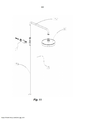
[030] O encanamento do conjunto de chuveiro compreende um cano reto e um cano curvado interconectados através de um conector, em que o cano reto é adaptado para se comunicar com a saída de água misturada direta ou indiretamente e o cabeçote de borrifador é conectado ao cano curvado de modo a estar no sentido descendente.[030] The shower set piping comprises a straight pipe and a curved pipe interconnected through a connector, where the straight pipe is adapted to communicate with the mixed water outlet directly or indirectly and the spray head is connected to the barrel curved so that it is in the downward direction.
[031] O encanamento, adicionalmente, tem um membro de fixação disposto sobre o mesmo, para fixar o encanamento em um corpo de parede.[031] The piping additionally has a fixing member disposed thereon to fix the piping to a wall body.
[032] O dispositivo de chuveiro de jato supracitado fornecido na presente invenção tem os seguintes efeitos técnicos: 1. No dispositivo de chuveiro de jato fornecido na presente invenção, uma agulha é encaixada dentro de um bocal, em que um espaço de fluxo de entrada de água fria e uma saída de água fria de jato são, ambos, formados entre o bocal e a agulha, em que um espaço de fluxo de entrada de água quente é formado entre o bocal e um corpo de válvula, uma entrada de água fria se comunica com a porta de água fria e o espaço de fluxo de entrada de água fria respectivamente e uma entrada de água quente se comunica com a porta de água quente e com o espaço de fluxo de entrada de água quente respectivamente, durante o uso, o ajuste simultâneo do espaço de fluxo de entrada de água fria, do espaço de fluxo de entrada de água quente e da saída de água fria de jato é alcançado ajustando-se o bocal para fazer com que o mesmo se mova ao longo da direção axial da válvula de injeção de jato, especificamente: quando o bocal se mover para fazer com que a área de corte transversal do espaço de fluxo de entrada de água fria diminua, a área da seção transversal do espaço de fluxo de entrada de água quente aumente de modo correspondente, para que se alcance o ajuste da temperatura da água misturada através da operação mais simples, mais importantemente, quando a área de corte transversal do espaço de fluxo de entrada de água fria diminuir, a área de corte transversal da saída de água fria de jato também diminui, de modo a garantir que quando a proporção de água fria for relativamente pequena, ainda haja a pressão de água relativamente alta mantida dentro do bocal, que tem melhor efeito de jato. Assim, a solução da técnica da presente invenção alcança melhor efeito de jato através de um modo de operação mais simples. 2. O dispositivo de chuveiro de jato fornecido na presente invenção compreende adicionalmente um membro giratório disposto de maneira giratória no corpo de válvula de uma maneira vedante e o membro giratório é conectado à agulha para acionar a agulha para girar com o mesmo; o bocal forma uma adaptação móvel axial com o membro giratório por meio de um meio de ajuste de movimento axial; em que o bocal se coordena com o corpo de válvula através de uma parte de limitação de rotação, de modo a evitar que o bocal gire em relação ao corpo de válvula à medida que o membro giratório aciona a agulha para girar e por meio do meio de ajuste de movimento axial para permitir que o bocal se mova na direção axial da agulha em relação ao corpo de válvula. Durante o uso, precisa-se apenas girar o membro giratório a fim de acionar a agulha para girar com o mesmo e à medida que o meio de ajuste de movimento axial é fornecido entre a agulha e o bocal e o bocal é constrito no corpo de válvula pela parte de limitação de rotação e, assim, é incapaz de girar relativamente, durante o processo de rotação da agulha, através do ajuste do meio de ajuste de movimento axial, o bocal irá se mover axialmente ao longo da agulha, para que, ajustando-se simultaneamente o espaço de fluxo de entrada de água fria, o espaço de fluxo de entrada de água quente e a saída de água fria de jato através do bocal, o projeto delicado alcance a operação simples. 3. No dispositivo de chuveiro de jato fornecido na presente invenção, o corpo de válvula da válvula de injeção de jato se comunica com um tubo de garganta na extremidade frontal ao longo da direção de jato de água fria e o tubo de garganta se comunica com uma extremidade aberta menor de um tubo de expansão com diâmetros variáveis, para que a água fria tenha velocidade maior, mas pressão menor quando emitindo jato a partir da saída de água fria de jato ao longo da extremidade frontal da agulha e, nesse instante, a pressão negativa é formada na parte do tubo de garganta em comunicação com o espaço de fluxo de entrada de água quente, de modo a bombear para dentro água quente e misturando-se de maneira suficiente a água fria e a água quente bombeadas para dentro garante-se através da instalação do tubo de garganta; o diâmetro interno do tubo de garganta é de 5 a 14 mm, o comprimento do tubo de garganta é entre 5 a 8 vezes seu diâmetro interno, um ângulo de expansão formada por linhas de extensão de uma parede externa do tubo de expansão e uma parede externa do tubo de garganta é de 5° a 15°, em que o tubo de garganta alcança a transferência de energia ao mesmo tempo em que garante a mistura suficiente de água fria e água quente e através da instalação do tubo de expansão e da escolha de um ângulo de expansão adequado para o tubo de garganta, a velocidade da água misturada é convertida na pressão, de modo a alcançar o melhor efeito de fluxo de saída de água. 4. No dispositivo de chuveiro de jato fornecido na presente invenção, o membro de sustentação compreende uma pluralidade de nervuras convexas uniformemente dispostas de maneira circunferencial ao redor do corpo de agulha e que se estendem em sua direção axial, em que cada duas nervuras convexas adjacentes têm uma passagem de fluido formada entre as mesmas. Cada nervura convexa compreende uma primeira parte e uma segunda parte, em que a dimensão radial da primeira parte é menor do que a dimensão radial da segunda parte e uma superfície externa da segunda parte se coordena com a cavidade interna do bocal. A primeira parte é disposta em direção a uma entrada do bocal, e sua dimensão radial é definida para ser menor do que aquela da segunda parte a fim de formar uma passagem de fluido através da coordenação com a parede interna do bocal para, assim, guiar uniformemente a água na entrada do bocal para as passagens de fluido formadas pelas nervuras convexas, de modo a garantir que a soma das áreas de corte transversal das passagens de fluido seja maior do que a área de corte transversal de jato da saída de água fria de jato do bocal e que uma pressão da água fria não incorra em perda antes de chegar à saída de água fria de jato do bocal, que leva ao melhor efeito de jato. 5. O dispositivo de chuveiro de jato fornecido na presente invenção compreende uma agulha usada na válvula de injeção de jato, em que um membro de sustentação é disposto circunferencialmente ao redor de seu corpo de agulha, para que quando sua agulha for instalada no bocal da válvula de injeção de jato, a superfície externa do membro de sustentação se coordene com uma parede interna do bocal de modo a limitar a posição do corpo de agulha, uma passagem de fluido seja formada no membro de sustentação, para que quando uma pressão do fluido que passa através do bocal seja relativamente grande ou muito grande e a velocidade de fluxo do fluido seja instável, é possível de se alcançar, sem influenciar o fluxo suave do fluido, para eficazmente evitar que a agulha se desvie da saída de água fria de jato do bocal ou oscile axialmente devido à pressão axial muito grande e assimétrica que a mesma suporta na direção radial e, então, afeta negativamente o efeito de jato do bocal. 6. O dispositivo de chuveiro de jato fornecido na presente invenção compreende uma agulha usada na válvula de injeção de jato, em que seu membro de sustentação compreende uma pluralidade de nervuras convexas uniformemente dispostas de maneira circunferencial ao redor do corpo de agulha e que se estendem ao longo de sua direção axial, em que cada uma das duas nervuras convexas adjacentes tem uma passagem de fluido formada entre as mesmas, de modo a facilitar o fluxo do fluido, ademais, cada nervura convexa compreende uma primeira parte de nervura e uma segunda parte de nervura e em que a dimensão radial da primeira parte de nervura é menor do que a dimensão radial da segunda parte de nervura, de modo a ter a capacidade de intensificar ainda mais o efeito de jato do bocal. 7. No dispositivo de chuveiro de jato fornecido na presente invenção, quando o bocal se move ao longo da direção axial, a entrada de água fria no corpo de válvula é disposta em direção à entrada do bocal por todo o trajeto. À medida que a entrada de água fria no corpo de válvula é disposta em direção à entrada do bocal por todo o trajeto, nessa circunstância, quando o bocal for movido ao longo da direção axial, o tamanho da abertura da entrada do bocal se mantém constante por todo o trajeto e a pressão de água na entrada do bocal se mantém constante com a pressão de água na entrada de água fria do corpo de válvula por todo o trajeto, de modo a garantir o melhor efeito de jato mesmo quando a proporção de água fria for relativamente pequena.[032] The aforementioned jet shower device provided in the present invention has the following technical effects: 1. In the jet shower device provided in the present invention, a needle is fitted inside a nozzle, in which an inlet flow space of cold water and a jet cold water outlet are both formed between the nozzle and the needle, wherein a hot water inlet flow space is formed between the nozzle and a valve body, a cold water inlet communicates with the cold water port and the cold water inlet flow space respectively, and a hot water inlet communicates with the hot water port and the hot water inlet flow space respectively, during use, simultaneous adjustment of the cold water inlet flow space, hot water inlet flow space and jet cold water outlet is achieved by adjusting the nozzle to make it move along the axial direction of the jet injection valve, specifically: when the nozzle moves to make the cross-sectional area of the cold water inlet flow space decrease, the cross-sectional area of the hot water inlet flow space correspondingly increases, so that it reaches adjusting the mixed water temperature through the simpler operation, more importantly, when the cross-sectional area of the cold water inlet flow space decreases, the cross-sectional area of the jet cold water outlet also decreases, so to ensure that when the proportion of cold water is relatively small, there is still relatively high water pressure maintained inside the nozzle, which has better jet effect. Thus, the technique solution of the present invention achieves better jet effect through a simpler mode of operation. 2. The jet shower device provided in the present invention further comprises a swivel member rotatably disposed on the valve body in a sealing manner and the swivel member is connected to the needle to drive the needle to rotate therewith; the mouthpiece forms an axial movable fit with the swivel member by means of an axial movement adjustment means; wherein the nozzle coordinates with the valve body through a rotation limiting portion so as to prevent the nozzle from rotating relative to the valve body as the swivel member actuates the needle to rotate and through the means adjust axial movement to allow the nozzle to move in the axial direction of the needle relative to the valve body. During use, one need only turn the swivel member in order to trigger the needle to rotate with it and as the axial movement adjustment means is provided between the needle and the mouthpiece and the mouthpiece is constricted into the body of valve by the rotation limitation part and thus is unable to rotate relatively, during the needle rotation process, by adjusting the axial movement adjustment means, the nozzle will move axially along the needle, so that, By simultaneously adjusting the cold water inlet flow space, the hot water inlet flow space and the jet cold water outlet through the nozzle, the delicate design achieves simple operation. 3. In the jet shower device provided in the present invention, the valve body of the jet injection valve communicates with a throat tube at the front end along the cold water jet direction and the throat tube communicates with a smaller open end of an expansion tube with variable diameters, so that the cold water has a higher velocity but a lower pressure when emitting a jet from the jet cold water outlet along the front end of the needle and, at that time, the Negative pressure is formed in the part of the throat tube in communication with the hot water inlet flow space, so as to pump hot water in, and sufficiently mixing the cold water and hot water pumped in ensures. if by installing the throat tube; the inner diameter of the throat tube is 5 to 14 mm, the length of the throat tube is between 5 to 8 times its inner diameter, an expansion angle formed by extension lines of an outer wall of the expansion tube and a wall The outer tube of the throat tube is 5° to 15°, where the throat tube achieves energy transfer while ensuring sufficient mixing of cold water and hot water and by installing the expansion tube and choosing From a suitable expansion angle for throat tube, the mixed water velocity is converted into pressure, so as to achieve the best outflow water effect. 4. In the jet shower device provided in the present invention, the support member comprises a plurality of convex ribs uniformly arranged circumferentially around the needle body and extending in its axial direction, wherein each two adjacent convex ribs have a fluid passage formed between them. Each convex rib comprises a first part and a second part, wherein the radial dimension of the first part is less than the radial dimension of the second part and an outer surface of the second part coordinates with the inner cavity of the mouthpiece. The first part is disposed towards an inlet of the nozzle, and its radial dimension is defined to be smaller than that of the second part in order to form a fluid passage through coordination with the inner wall of the nozzle to thereby guide evenly water at the nozzle inlet to the fluid passages formed by the convex ribs, so as to ensure that the sum of the cross-sectional areas of the fluid passages is greater than the jet cross-sectional area of the cold water outlet of nozzle jet and that a cold water pressure does not incur loss before reaching the nozzle jet cold water outlet, which leads to the best jet effect. 5. The jet shower device provided in the present invention comprises a needle used in the jet injection valve, in which a support member is circumferentially disposed around its needle body, so that when its needle is installed in the nozzle of the jet injection valve, the outer surface of the support member coordinates with an inner wall of the nozzle so as to limit the position of the needle body, a fluid passage is formed in the support member, so that when a fluid pressure that passes through the nozzle is relatively large or very large and the fluid flow velocity is unstable, it is possible to achieve, without influencing the smooth fluid flow, to effectively prevent the needle from deviating from the jet cold water outlet of the nozzle or oscillates axially due to the very large and asymmetrical axial pressure it supports in the radial direction and thus negatively affects the nozzle jet effect. 6. The jet shower device provided in the present invention comprises a needle used in the jet injection valve, its support member comprising a plurality of convex ribs uniformly arranged circumferentially around the needle body and extending along its axial direction, each of the two adjacent convex ribs having a fluid passage formed therebetween so as to facilitate fluid flow, moreover, each convex rib comprises a first rib part and a second rib part of rib part and wherein the radial dimension of the first rib part is less than the radial dimension of the second rib part, so as to have the ability to further intensify the jetting effect of the nozzle. 7. In the jet shower device provided in the present invention, when the nozzle moves along the axial direction, the cold water inlet in the valve body is arranged towards the inlet of the nozzle along the entire path. As the cold water inlet into the valve body is disposed towards the nozzle inlet throughout the entire path, in this circumstance, when the nozzle is moved along the axial direction, the nozzle inlet opening size remains constant throughout the entire path and the water pressure at the nozzle inlet remains constant with the water pressure at the valve body cold water inlet throughout the entire path, so as to ensure the best jet effect even when the water ratio cold is relatively small.
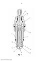
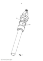
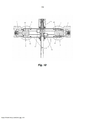
[033] A fim de tornar o conteúdo da presente invenção claramente compreendido mais facilmente, a descrição detalhada adicional da presente invenção é fornecida abaixo, com referência aos desenhos em anexo, em que: - a Figura 1 é um diagrama esquemático estrutural da bobina de válvula da Realização 1, formada através da coordenação do bocal, da agulha e do membro giratório; - a Figura 2 é um diagrama esquemático estrutural da agulha da Realização 1; - a Figura 3 é um diagrama esquemático estrutural do bocal da Realização 1; - a Figura 4 é um diagrama esquemático estrutural da válvula de injeção de jato da Realização 1; - a Figura 5 é um diagrama esquemático estéreo-estrutural da válvula de injeção de jato da Realização 1; - a Figura 6 é um diagrama esquemático estrutural do membro de sustentação na agulha da Realização 3; - a Figura 7 é um diagrama esquemático estrutural do membro de sustentação na agulha da Realização 2; - a Figura 8 é um diagrama esquemático estéreo-estrutural da base da presente invenção; - Figura 9 é um diagrama esquemático estéreo-estrutural da bobina de cerâmica da presente invenção; - Figura 10 é uma vista em corte transversal da estrutura do misturador de água de jato da presente invenção; - Figura 11 é uma vista explodida da estéreo-estrutura do conjunto de chuveiro do dispositivo de chuveiro de jato da presente invenção.[033] In order to make the content of the present invention more easily understood, further detailed description of the present invention is provided below, with reference to the attached drawings, in which: - Figure 1 is a schematic structural diagram of the coil of the valve of
[034] A explicação de marcações nos desenhos em anexo: A-corpo de mistura de água; A1-porta de água fria; A2-porta de água quente; a - base; a1 - admissão de fluxo de água; b - bobina; b1 - abertura de ajuste de fluxo de água; c - manípulo; B - válvula de injeção de jato; B1 - entrada de água fria; B2 - entrada de água quente; 1 - corpo de válvula; 13 - membro giratório; 3 - bocal; 31 - segmento de pressurização; 32 - saída de água fria de jato; 33 - parte de limitação de rotação; 34 - parte cônica de bocal; 35 - entrada; 4 - agulha; 41 - corpo de agulha; 42 - parte cônica de agulha; 43 - anel circular; 44 - nervura convexa; 44a - primeira parte; 44b - segunda parte; 45 - placa de sustentação anular; 46 - furo de desvio de fluxo; 48 - elemento de aperto; 5 - passagem de fluido; 6 - tubo de garganta; 7 - tubo de expansão; 8 - espaço de fluxo de entrada de água quente; 9 - espaço de fluxo de entrada de água fria; 15 - encanamento; 16 - cabeçote de borrifador; 17 - membro de fixação; 151 - cano reto; 152 - cano curvado.[034] The explanation of markings on the attached drawings: A-water mixture body; A1-cold water port; A2-hot water port; the base; a1 - water flow admission; b - coil; b1 - water flow adjustment opening; c - handle; B - jet injection valve; B1 - cold water inlet; B2 - hot water inlet; 1 - valve body; 13 - swivel member; 3 - mouthpiece; 31 - pressurization segment; 32 - jet cold water outlet; 33 - rotation limitation part; 34 - conical nozzle part; 35 - entrance; 4 - needle; 41 - needle body; 42 - conical needle part; 43 - circular ring; 44 - convex rib; 44a - first part; 44b - second part; 45 - annular support plate; 46 - flow diversion hole; 48 - clamping element; 5 - fluid passage; 6 - throat tube; 7 - expansion tube; 8 - hot water inlet flow space; 9 - cold water inlet flow space; 15 - plumbing; 16 - spray head; 17 - fixation member; 151 - straight barrel; 152 - curved barrel.
[035] A descrição detalhada da solução da técnica da presente invenção é fornecida da seguinte forma, em conjunto com os desenhos em anexo e as realizações específicas.[035] The detailed description of the solution of the technique of the present invention is provided as follows, together with the attached drawings and the specific embodiments.
[036] Conforme mostrado na Figura 10 e na Figura 11, essa realização fornece um dispositivo de chuveiro de jato, que compreende um corpo de mistura de água (A), uma válvula de injeção de jato (B) e um conjunto de chuveiro, em que o corpo de mistura de água (A) tem uma porta de água fria (A1), uma porta de água quente (A2) e uma saída de água misturada, em que a válvula de injeção de jato (B) tem uma entrada de água fria (B1) e uma entrada de água quente (B2), a porta de água fria (A1) se comunica com a entrada de água fria (B1), a porta de água quente (A2) se comunica com a entrada de água quente (B2), os volumes de água fria e de água quente que fluem para a válvula de injeção de jato (B) são ajustáveis ajustando-se os tamanhos da abertura da porta de água fria (A1) e da porta de água quente (A2), respectivamente e o conjunto de chuveiro tem um encanamento 15 que se comunica com a saída de água misturada do corpo de mistura de água (A) e um cabeçote de borrifador 16 que se comunica com o encanamento 15.[036] As shown in Figure 10 and Figure 11, this embodiment provides a jet shower device, comprising a water mixing body (A), a jet injection valve (B) and a shower assembly, wherein the water mixing body (A) has a cold water port (A1), a hot water port (A2) and a mixed water outlet, wherein the jet injection valve (B) has an inlet of cold water (B1) and a hot water inlet (B2), the cold water port (A1) communicates with the cold water inlet (B1), the hot water port (A2) communicates with the hot water (B2), the volumes of cold water and hot water flowing to the jet injection valve (B) are adjustable by adjusting the cold water port (A1) and hot water port opening sizes (A2), respectively, and the shower assembly has a piping 15 that communicates with the mixed water outlet of the water mixing body (A) and a
[037] Nessa realização, o tamanho da abertura da porta de água fria (A1) é ajustável através de um interruptor de regulagem de água fria, em que o tamanho da abertura da porta de água quente (A2) é ajustável através de um interruptor de regulagem de água quente, em que o interruptor de regulagem de água fria e o interruptor de regulagem de água quente dessa realização têm a mesma estrutura.[037] In this embodiment, the size of the opening of the cold water door (A1) is adjustable through a cold water adjustment switch, where the size of the opening of the hot water door (A2) is adjustable through a switch of hot water regulation, in which the cold water regulation switch and the hot water regulation switch of this realization have the same structure.
[038] O interruptor de regulagem de água fria (ou o interruptor de regulagem de água quente) compreende uma base (a) encaixada no corpo de mistura de água (A), uma bobina (b) em coordenação com a base (a) e um manípulo (c) para acionar a bobina (b) para girar.[038] The cold water regulation switch (or the hot water regulation switch) comprises a base (a) fitted to the water mixing body (A), a coil (b) in coordination with the base (a) and a handle (c) to drive the coil (b) to rotate.
[039] Conforme mostrado na Figura 8, a base (a) é cilíndrica, um furo de comunicação é fornecido na base (a), em que a base (a) se comunica com a porta de água fria (A1) (ou a porta de água quente (A2)) através do furo de comunicação e a parede lateral da base (a) tem uma admissão de fluxo de água (a1) formada no mesmo para se comunicar com um cano de fornecimento de água fria.[039] As shown in Figure 8, the base (a) is cylindrical, a communication hole is provided in the base (a), where the base (a) communicates with the cold water port (A1) (or the hot water port (A2)) through the communication hole and the base side wall (a) has a water flow inlet (a1) formed therein to communicate with a cold water supply pipe.
[040] Conforme mostrado na Figura 9, a bobina de cerâmica (b) compreende um corpo principal cilíndrico, em que a parede lateral do corpo principal cilíndrico tem uma abertura de ajuste de água fria (b1) formada na mesma e tem uma parte de aperto poligonal e uma parte de conexão rosqueada, durante a instalação, uma extremidade da bobina (b) é inserida na base (a) de modo a permitir que a abertura de ajuste de fluxo de água (b1) da bobina (b) corresponda à admissão de fluxo de água (a1) da base (a) na direção axial, em que essa extremidade da bobina (b) é presa na borda da parede lateral da base (a) através da parte de aperto poligonal e a outra extremidade da bobina (b) é inserida no manípulo (c) de modo que fique presa ao manípulo (c) através de uma cavilha de parafuso engatada com a rosca de parafuso dentro de uma ranhura axial da bobina (b).[040] As shown in Figure 9, the ceramic coil (b) comprises a cylindrical main body, wherein the side wall of the cylindrical main body has a cold water adjustment opening (b1) formed therein and has a part of polygonal clamping and a threaded connecting part, during installation, one end of the coil (b) is inserted into the base (a) so as to allow the water flow adjustment opening (b1) of the coil (b) to match the water flow intake (a1) from the base (a) in the axial direction, where this end of the coil (b) is secured to the edge of the base side wall (a) through the polygonal clamping part and the other end of the coil (b) is inserted into the handle (c) so that it is secured to the handle (c) via a screw bolt engaged with the screw thread within an axial groove of the coil (b).
[041] Durante o uso, o manípulo (c) é girado, o qual aciona a bobina (b) para girar e, então, aciona a abertura de ajuste de fluxo de água (b1) na bobina (b) para girar, de modo a alterar o tamanho de sobreposição das aberturas da abertura de ajuste de fluxo de água (b1) e da admissão de fluxo de água (a1) na base (a), em que quando a abertura de ajuste de fluxo de água (b1) e a admissão de fluxo de água (a1) se corresponderem entre si de completamente, o volume de água fria que flui para o corpo de mistura de água (A) é máximo, de modo a permitir que o volume de água fria que flui da porta de água fria (A1) para a válvula de injeção de jato (B) seja máximo e quando a abertura de ajuste de fluxo de água (b1) e a admissão de fluxo de água (a1) forem desalinhadas uma com relação à outra por completo, a admissão de fluxo de água (a1) é fechada e, assim, não tem a capacidade de importar a água fria para o corpo de mistura de água (A).[041] During use, the knob (c) is rotated, which drives the coil (b) to rotate and then actuates the water flow adjustment opening (b1) on the coil (b) to rotate, of to change the overlapping size of the openings of the water flow adjustment opening (b1) and the water flow inlet (a1) at the base (a), where when the water flow adjustment opening (b1) and the water flow inlet (a1) if they match each other completely, the volume of cold water flowing into the water mixing body (A) is maximum, so as to allow the volume of cold water flowing from the cold water port (A1) for the jet injection valve (B) is maximum and when the water flow adjustment opening (b1) and the water flow inlet (a1) are misaligned with respect to each other by When completed, the water flow inlet (a1) is closed and thus does not have the ability to import cold water into the water mixing body (A).
[042] A bobina (b) pode ser uma bobina de cerâmica, uma bobina de içamento ou outras formas de bobina.[042] The coil (b) can be a ceramic coil, a lifting coil or other forms of coil.
[043] O princípio de ajustar água quente é idêntico ao princípio de ajustar água fria conforme descrito acima.[043] The principle of setting hot water is identical to the principle of setting cold water as described above.
[044] A descrição detalhada da estrutura da válvula de injeção de jato (B) do dispositivo de chuveiro de jato é fornecida abaixo, com referência aos desenhos em anexo.[044] The detailed description of the structure of the jet injection valve (B) of the jet shower device is given below, with reference to the attached drawings.
[045] Nessa realização, conforme mostrado na Figura 1, a válvula de injeção de jato (B) tem um corpo de válvula 1, um membro giratório 13, um bocal 3, uma agulha 4, um tubo de garganta 6, um tubo de expansão 7 e uma saída de água. O corpo de válvula 1 é uma carcaça com uma cavidade oca, em que o bocal 3, a agulha 4 e o membro giratório 13 são fornecidos dentro da cavidade oca do corpo de válvula 1 e uma entrada de água fria (B1) e uma entrada de água quente (B2) são formadas na parede lateral do corpo de válvula 1.[045] In this embodiment, as shown in Figure 1, the jet injection valve (B) has a
[046] O membro giratório 13 é disposto de maneira giratória no corpo de válvula 1 de uma maneira vedante e um meio de ajuste de movimento axial forma uma adaptação móvel axial com o bocal 3 e permite que um movimento giratório do membro giratório 13 seja convertido em um movimento axial do bocal 3.[046] The
[047] Especificamente, por exemplo, o meio de ajuste de movimento axial pode ser um suporte e uma engrenagem engatada com o mesmo para transmitir uma força de acionamento, isto é, o suporte é fornecido no bocal 3 e o membro giratório 13 está em ligação mecânica com a engrenagem para acionar um movimento axial do bocal 3.[047] Specifically, for example, the axial movement adjustment means can be a support and a gear engaged therewith to transmit a driving force, i.e., the support is provided in the
[048] Conforme mostrado na Figura 1, o membro giratório 13 compreende um cilindro e um botão giratório fornecido em uma extremidade do cilindro, em que o cilindro tem um recesso axial fornecido em sua direção axial e um recesso radial, quando se encaixa o membro giratório 13 dentro do corpo de válvula 1, o botão giratório se estende para fora do corpo de válvula 1, a parede externa superior do corpo de válvula é fixada ao recesso radial e um elemento de aperto 48 é encaixado no recesso radial, de modo a encaixar o membro giratório 13 dentro do corpo de válvula 1 e a impedir que o mesmo se mova axialmente em relação ao corpo de válvula 1. Além disso, a rosca de parafuso externa é fornecida no membro giratório 13.[048] As shown in Figure 1, the
[049] Conforme mostrado na Figura 2, a agulha 4 tem um corpo de agulha cilíndrico 41, em que uma extremidade do corpo de agulha cilíndrico 41 é inserida no recesso axial do membro giratório 13 para permitir que a agulha 4 tenha a capacidade de girar junto com o membro giratório 13 sem gerar qualquer deslocamento giratório em relação ao membro giratório 13, em que uma parte cônica de agulha 42 é formada na outra extremidade do corpo de agulha 41, o diâmetro da parte cônica de agulha 42 diminui linearmente a partir de sua raiz até sua ponta de injeção de jato, de modo a garantir que o efeito de jato linear, o ângulo cônico da parte cônica de agulha 42 seja de 10° a 150°, o ângulo cônico da parte cônica de bocal 34 seja maior ou igual ao ângulo cônico da parte cônica de agulha 42, em que a extremidade maior da parte cônica de agulha 42 é conectada no corpo de agulha 41, uma pluralidade de nervuras convexas 44 são uniformemente dispostas de maneira circunferencial ao redor do corpo de agulha 41 para formar um membro de sustentação, as nervuras convexas 44 se estendem na direção axial do corpo de agulha 41, a nervura convexa 44 compreende uma primeira parte 44a e uma segunda parte 44b, em que a primeira parte 44a é disposta em direção a uma entrada de água fria de bocal do bocal e sua dimensão radial é menor do que a dimensão radial da segunda parte 44b, de modo a formar uma passagem de fluido 5 através da coordenação com a parede de cavidade interna do bocal e uma superfície externa da segunda parte 44b se coordena com a cavidade interna do bocal 3. Nessa realização, a dimensão radial da segunda parte 44b é três vezes a dimensão radial da primeira parte 44a e em que a primeira parte 44a é menor do que uma segunda parte 44b, a passagem de fluido é formada no membro de sustentação. O comprimento axial da segunda parte 44b é menor do que o comprimento axial da primeira parte 44a e o comprimento axial da primeira parte 44a é a soma do comprimento da entrada 35 do bocal 3 na direção axial da agulha 4 mais o comprimento de curso axial do bocal 3.[049] As shown in Figure 2, the
[050] Conforme mostrado na Figura 3, o bocal 3 compreende um corpo principal cilíndrico com cavidade interna, uma entrada 35 para fluir a água fria é formada na parede lateral do corpo principal cilíndrico, em que uma extremidade do corpo principal cilíndrico é diretamente formada em uma porca hexagonal com cavidade interna, quando se encaixa o bocal 3 dentro do corpo de válvula 1, as bordas da porca hexagonal são presas na parede interna do corpo de válvula 1, de modo a impedir que o bocal 3 gire em relação ao corpo de válvula 1, portanto, a porca hexagonal serve como uma parte de limitação de rotação 33 que limita a rotação relativa do bocal 3, em que uma parte cônica de bocal 34 é formada na outra extremidade do corpo principal cilíndrico e a extremidade aberta menor da parte cônica de bocal 34 serve como a saída de água fria de jato 32, cujo diâmetro da abertura é de 3 a 10 mm, de preferência de 4 a 6 mm. Além disso, a rosca de parafuso interna também é formada no bocal 3 e quando o bocal 3 for encaixado dentro do corpo de válvula 1, um encaixe de parafuso-rosca é formado entre a rosca de parafuso interna no bocal 3 e a rosca de parafuso externa no membro giratório 13.[050] As shown in Figure 3, the
[051] Conforme mostrado na Figura 4, a válvula de injeção de jato (B) compreende também um tubo de garganta 6 encaixado no corpo de válvula 1, que se estende na direção de jato da água fria, em que o tubo de garganta 6 é colocado a uma certa distância da saída de água fria de jato 32 e essa distância é menor ou igual ao comprimento de curso do encaixe de parafuso-rosca entre a rosca de parafuso interna no bocal 3 e a rosca de parafuso externa no membro giratório 13. O tubo de garganta 6 se comunica adicionalmente com uma extremidade aberta menor de um tubo de expansão 7 com diâmetros variáveis, em que o diâmetro interno do tubo de garganta 6 é de 5 a 14 mm, de preferência de 6 a 10 mm, o comprimento do tubo de garganta 6 está dentro de 5 a 8 vezes seu diâmetro interno e um ângulo de expansão formada por linhas de extensão de uma parede externa do tubo de expansão 7 e uma parede externa do tubo de garganta 6 é de 5° a 15°.[051] As shown in Figure 4, the jet injection valve (B) also comprises a
[052] Durante a instalação, o corpo de válvula 1 é revestido fora do bocal 3, em que a parte de limitação de rotação 33 do bocal 3 é presa na parede interna do corpo de válvula 1, de modo a impedir que o bocal 3 gire em relação ao corpo de válvula 1 e a entrada 35 do bocal 3 está em correspondência com a entrada de água fria (B1) do corpo de válvula 1; então, o corpo de agulha 41 da agulha 4 é inserido no recesso axial do membro giratório 13, de modo a permitir que a agulha 4 tenha a capacidade de girar junto com o membro giratório 13; subsequentemente, o membro giratório 13 e a agulha 4 que foram encaixados juntos são inseridos na cavidade interna do bocal 3 dentro do corpo de válvula 1 e um encaixe de parafuso-rosca é formado entre a rosca de parafuso interna no bocal 3 e a rosca de parafuso externa no membro giratório 13, de modo a formar a bobina de válvula de injeção de jato conforme mostrado na Figura 1; finalmente, o tubo de garganta 6 e o tubo de expansão 7 são encaixados no corpo de válvula 1, de modo a formar a válvula de injeção de jato (B) conforme mostrado na Figura 4 e Figura 5.[052] During installation, the
[053] Conforme mostrado na Figura 4, a válvula de injeção de jato (B) compreende um corpo de válvula 1, um bocal 3, uma agulha 4, um tubo de garganta 6, um tubo de expansão 7 e uma saída de água. Uma entrada de água fria (B1) e uma entrada de água quente (B2) são formadas no corpo de válvula 1, o bocal 3 é encaixado dentro do corpo de válvula 1 e é preso na parede interna do corpo de válvula 1 através da parte de limitação de rotação 33 e depois de formar uma coordenação com o membro giratório 13, a agulha 4 é inserida no bocal 3, de modo a formar um encaixe de parafuso-rosca entre a rosca de parafuso interna no bocal 3 e a rosca de parafuso externa no membro giratório 13, também, um espaço de fluxo de entrada de água fria 9 e uma saída de água fria de jato 32 são, ambos, formados entre o bocal 3 e a agulha 4, em que um espaço de fluxo de entrada de água quente 8 é formado entre o bocal 3 e o corpo de válvula 1, a entrada de água fria (B1) se comunica com a porta de água fria (A1) e o espaço de fluxo de entrada de água fria 9 respectivamente, a entrada de água quente (B2) se comunica com a porta de água quente (A2) e o espaço de fluxo de entrada de água quente 8 respectivamente e a entrada 35 do bocal 3 corresponde à entrada de água fria (B1) do corpo de válvula 1.[053] As shown in Figure 4, the jet injection valve (B) comprises a
[054] Durante o uso, rodando-se o membro giratório 13, a agulha 4 é acionada para girar junto com o membro giratório 13 e, devido a esse fato, por um lado, o bocal 3 é preso dentro do corpo de válvula 1 através da parte de limitação de rotação 33 de modo a não ter a capacidade de girar, e, por outro lado, o bocal 3 forma um encaixe de parafuso-rosca com a rosca de parafuso externa no membro giratório 13 através de sua rosca de parafuso interna, para que o bocal 3 tenha a capacidade de se mover na direção axial do corpo de válvula 1, quando se roda o membro giratório 13, desse modo, alterando simultaneamente as áreas em corte transversal do espaço de fluxo de entrada de água fria 9, do espaço de fluxo de entrada de água quente 8 e da saída de água fria de jato 32; durante esse processo, a entrada 35 do bocal 3 sempre corresponde à entrada de água fria (B1), isto é, durante o processo de movimento axial do bocal 3, a pressão de água fria na entrada 35 sempre se mantém consistente com a pressão de água fria na entrada de água fria (B1) no corpo de válvula 1.[054] During use, by rotating the
[055] De modo a garantir o melhor efeito de jato, nessa realização, entre o membro de sustentação do corpo de agulha 41 e a parte cônica de agulha 42 há um segmento de pressurização 31, em que o segmento de pressurização 31 se coordena com a parede interna do bocal 3 para formar o espaço de fluxo de entrada de água fria 9, o segmento de pressurização 31 é cilíndrico, com um diâmetro maior ou ligeiramente menor do que o diâmetro da saída de água fria de jato 32 do bocal 3. A expressão “maior do que”, no presente, se refere ao fato de que, depois de a parte cônica de agulha 42 se coordenar completamente com a saída de água fria de jato 32, a saída de água fria de jato 32 é completamente vedada, de modo a impedir que a água fria saia por jato para fora da saída de água fria de jato 32. A expressão “ligeiramente menor do que”, no presente, se refere ao fato de que, o diâmetro do segmento de pressurização 31 e o diâmetro da saída de água fria de jato 32 têm um valor de diferença pequeno quando comparados entre si, isto é, depois de a parte cônica de agulha 42 se coordenar completamente com a saída de água fria de jato 32, há uma ligeira lacuna entre a superfície circunferencial externa do segmento de pressurização 31 e a superfície circunferencial interna da saída de água fria de jato 32 e, muito embora uma ligeira quantidade de água fria saia por jato para fora da saída de água fria de jato 32 através dessa lacuna, sua ligeira influência na água quente que flui pela parede externa do bocal 3 é desprezível. O diâmetro da parte cônica de agulha 42 diminui gradualmente na direção de jato e seu comprimento é menor ou igual ao comprimento de curso móvel do bocal 3.[055] In order to ensure the best jet effect, in this realization, between the needle
[056] Com relação ao dispositivo de chuveiro de jato da presente invenção, a escolha de parâmetros de seus respectivos componentes tem influência significativa no efeito de bombeamento de água quente do dispositivo de chuveiro de jato e foi provado por meio de experimentos que toda a estrutura do dispositivo de chuveiro de jato da Realização 1 em conjunto com os parâmetros específicos possibilita que o dispositivo tenha um efeito de bombeamento muito bom através de pressão negativa mesmo quando a quantidade de água fria é relativamente pequena, conforme indicado pelos resultados de teste detalhados listados na Tabela 1, enquanto a Tabela 2 indica que, quando o dispositivo for ajustado para o estado intermediário de água fria, toda a estrutura do misturador de água de jato da Realização 1 em conjunto com os parâmetros específicos também possibilita que o dispositivo tenha o efeito de bombeamento muito bom através da pressão negativa durante o uso. TABELA 1

[057] Conforme mostrado na Figura 7, essa realização fornece um dispositivo de chuveiro de jato aperfeiçoado com base na Realização 1 e o aperfeiçoamento foca, principalmente, no fato de que o membro de sustentação da agulha 4 emprega uma estrutura diferente. Nessa realização, o membro de sustentação é uma placa de sustentação anular 45 formada no corpo de agulha 41 e a placa de sustentação anular 45 é dotado de uma pluralidade de furos de desvio de fluxo 46 formada na mesma e que serve como a passagem de fluido 5. Essa configuração possibilita o fluxo de entrada fluente de água fria e tem a capacidade de sustentar simetricamente a agulha 4.[057] As shown in Figure 7, this embodiment provides an improved jet shower device based on
[058] Conforme mostrado na Figura 6, essa realização fornece um dispositivo de chuveiro de jato aperfeiçoado com base na Realização 1 e o aperfeiçoamento foca principalmente no fato de que o membro de sustentação da agulha 4 emprega uma estrutura diferente. Nessa realização, o membro de sustentação é um anel circular 43, em que o anel circular 43 está conectado no corpo de agulha 41 através de uma pluralidade de tiras de nervura 40 e em que cada duas tiras de nervura adjacentes 40 têm uma passagem de fluido 5 formada entre as mesmas. Essa configuração não apenas garante o fluxo de entrada fluente de água fria, como também tem a capacidade de sustentar simetricamente a agulha 4.[058] As shown in Figure 6, this embodiment provides an improved jet shower device based on
[059] Essa realização fornece um dispositivo de chuveiro de jato aperfeiçoado com base na Realização 1 e o aperfeiçoamento foca principalmente no fato de que a parte de limitação de rotação 33 no bocal 3 emprega uma estrutura diferente. Nessa realização, a parte de limitação de rotação 33 é um membro convexo formado na superfície circunferencial de uma extremidade do bocal 3 e uma ranhura guia na direção axial para se coordenar, de maneira deslizante, com o membro convexo é formada na parede interna do corpo de válvula 1.[059] This embodiment provides an improved jet shower device based on
[060] Essa realização fornece um dispositivo de chuveiro de jato aperfeiçoado com base na Realização 1 e o aperfeiçoamento foca principalmente no fato de que a parte de limitação de rotação 33 no bocal 3 emprega uma estrutura diferente. Nessa realização, a parte de limitação de rotação 33 é um membro convexo formado na parede interna do corpo de válvula 1 e uma ranhura guia na direção axial para se coordenar, de maneira deslizante, com o membro convexo é formada em uma extremidade do bocal 3.[060] This embodiment provides an improved jet shower device based on
[061] Conforme mostrado na Figura 11, o encanamento 15 do conjunto de chuveiro compreende um cano reto 151 e um cano curvado 152 interconectados através de um conector como um embuchamento de cobre vermelho e uma porca de fixação, em que o cano reto 151 é adaptado para se comunicar com a saída de água misturada direta ou indiretamente, isto é, o cano reto 151 e a saída de água misturada podem ter uma válvula de mudança conforme descrito abaixo conectada entre os mesmos e o cabeçote de borrifador 16 está conectado ao cano curvado 152 de modo a estar para baixo.[061] As shown in Figure 11, the piping 15 of the shower assembly comprises a straight pipe 151 and a
[062] Opcionalmente, o cano reto 151 e o tubo de expansão 7 com diâmetros variáveis podem ser interconectados através de um conector como um embuchamento de cobre vermelho e uma porca de fixação.[062] Optionally, straight pipe 151 and
[063] Além disso, durante o uso real, esse conjunto de chuveiro pode ser fixado em um corpo de parede como exigido, isto é, o encanamento 15 tem, adicionalmente, um membro de fixação 17 disposto sobre o mesmo, para a fixação do encanamento 15 em um corpo de parede, especificamente, conforme mostrado na Figura 11, esse membro de fixação 17 compreende uma base de fixação e uma luva de expansão unidas, assim como, uma cavilha de parafuso automática com formato transversal.[063] Furthermore, during actual use, this shower assembly can be fixed to a wall body as required, i.e. the piping 15 additionally has a fixing
[064] O encanamento 15 e o misturador de água de jato (A) podem se comunicar entre si diretamente ou uma válvula de mudança (não mostrada nos desenhos) pode ser adicionada entre os mesmos, em que a entrada da válvula de mudança se comunica com o misturador de água de jato (A) e a saída da válvula de mudança se comunica com o encanamento 15 e a saída lateral da válvula de mudança se comunica com uma mangueira e, subsequentemente, se comunica com um cabeçote de borrifo portátil, durante o uso, virando-se o manípulo da válvula de mudança, o fluxo de saída de água pode ser trocado entre o cabeçote de borrifador 16 e o cabeçote de borrifo portátil.[064] The
[065] A estrutura da válvula de mudança pode ser uma válvula de esfera, uma bobina de válvula de cerâmica, uma bobina de içamento de válvula, etc.[065] The shift valve frame can be a ball valve, ceramic valve coil, valve lift coil, etc.
[066] Além disso, a fim de se obter o melhor efeito de fluxo de saída de água, as áreas em corte transversal do orifício interno do cabeçote de borrifador 16, do encanamento 15, do conector como o embuchamento de cobre vermelho e da válvula de mudança são configuradas para serem maiores do que a área em corte transversal do orifício interno do tubo de garganta 6, idealmente, maiores do que a área em corte transversal da saída de água do tubo de expansão 7.[066] In addition, in order to obtain the best outflowing water effect, the cross-sectional areas of the internal orifice of the
[067] Obviamente, as realizações supracitadas são meramente destinadas a descrever claramente os exemplos, em vez de limitar o escopo de implantação da invenção. Para um técnico no assunto, várias alterações e modificações em outras formas diferentes podem ser feitas com base na descrição supracitado. É desnecessário e impossível listar exaustivamente todos os modos de implantação no presente. No entanto, quaisquer alterações ou modificações óbvias derivadas da descrição supracitada são destinadas a serem abrangidas no escopo de proteção da presente invenção.[067] Obviously, the aforementioned embodiments are merely intended to clearly describe the examples, rather than limiting the scope of implementation of the invention. For a person skilled in the art, various changes and modifications in other different ways can be made based on the aforementioned description. It is unnecessary and impossible to exhaustively list all deployment modes at present. However, any obvious changes or modifications deriving from the aforementioned description are intended to fall within the scope of protection of the present invention.
Claims (20)
Applications Claiming Priority (3)
| Application Number | Priority Date | Filing Date | Title |
|---|---|---|---|
| CN201310154267.1 | 2013-04-27 | ||
| CN201310154267.1A CN103775681B (en) | 2013-04-27 | 2013-04-27 | Jet shower device |
| PCT/CN2013/084285 WO2014173073A1 (en) | 2013-04-27 | 2013-09-26 | Shower jet device |
Publications (2)
| Publication Number | Publication Date |
|---|---|
| BR112015002211A2 BR112015002211A2 (en) | 2017-07-04 |
| BR112015002211B1 true BR112015002211B1 (en) | 2021-08-31 |
Family
ID=50568257
Family Applications (1)
| Application Number | Title | Priority Date | Filing Date |
|---|---|---|---|
| BR112015002211-1A BR112015002211B1 (en) | 2013-04-27 | 2013-09-26 | JET SHOWER DEVICE |
Country Status (7)
| Country | Link |
|---|---|
| US (1) | US9725890B2 (en) |
| CN (1) | CN103775681B (en) |
| BR (1) | BR112015002211B1 (en) |
| IN (1) | IN2014MN00430A (en) |
| MX (1) | MX345744B (en) |
| WO (1) | WO2014173073A1 (en) |
| ZA (1) | ZA201500289B (en) |
Families Citing this family (12)
| Publication number | Priority date | Publication date | Assignee | Title |
|---|---|---|---|---|
| CN105105675A (en) * | 2015-08-29 | 2015-12-02 | 上虞市优耐德管业有限公司 | Self-absorption portable-type simple shower |
| CN105105674A (en) * | 2015-08-29 | 2015-12-02 | 上虞市优耐德管业有限公司 | Self-absorption portable-type shower |
| CN106040462B (en) * | 2016-08-10 | 2018-10-02 | 天津瑞金华鼎科技有限公司 | The adjustable underwater relief arrangement of flow |
| AU2017258849A1 (en) * | 2017-11-07 | 2019-05-30 | Baker, Shaun Damien MR | Mixer Test Cartridge |
| CN108443533B (en) * | 2018-05-17 | 2023-05-23 | 箭牌家居集团股份有限公司 | Supercharging control valve for bathroom cold and warm water supply |
| CN110906555B (en) * | 2018-09-18 | 2023-11-24 | 芜湖美的厨卫电器制造有限公司 | Water mixing device for water heater and water heater |
| CN110394244A (en) * | 2019-05-21 | 2019-11-01 | 林仙明 | A kind of jet stream spool |
| WO2021202925A1 (en) * | 2020-04-03 | 2021-10-07 | Kohler Co. | Digital rain showerhead |
| CN111851660B (en) * | 2020-07-28 | 2021-07-20 | 浙江大学 | Rotatable combined shower device |
| CN112524286B (en) * | 2020-11-30 | 2022-10-14 | 宁波方太厨具有限公司 | Water mixing valve and hot water circulation system comprising same |
| CN115770670B (en) * | 2022-12-27 | 2023-09-19 | 北京科技大学 | Cavitation jet nozzle device, equipment and method |
| CN116406144B (en) * | 2023-05-23 | 2023-08-18 | 常州贺斯特科技股份有限公司 | Fine casting aluminum water cooling plate embedded with stainless steel pipeline and use method thereof |
Family Cites Families (21)
| Publication number | Priority date | Publication date | Assignee | Title |
|---|---|---|---|---|
| JPH0668174B2 (en) | 1989-03-29 | 1994-08-31 | 株式会社イナックス | Shower bath faucet and its switching valve |
| CN2221762Y (en) | 1995-05-12 | 1996-03-06 | 国营华兴电子机器厂 | Cold-hot fluid mixed jet device |
| US6089462A (en) * | 1998-02-04 | 2000-07-18 | Officina Meccanica Ruga Osvaldo | Thermostatic mixing valve |
| US6042015A (en) * | 1998-03-17 | 2000-03-28 | Eveleigh; Robert | Fail-safe proportional mixing valve |
| DE19901852A1 (en) * | 1999-01-19 | 2000-07-20 | Hansgrohe Ag | Thermostatic valve |
| JP4591860B2 (en) | 2000-03-17 | 2010-12-01 | Toto株式会社 | Hot water tap |
| US7198059B2 (en) * | 2000-10-25 | 2007-04-03 | Grundfos Pumps Manufacturing Company | Apparatus and system for retrofitting water control valves |
| JP4254126B2 (en) * | 2002-01-15 | 2009-04-15 | 株式会社デンソー | Ejector for vapor compression refrigeration cycle |
| CN201007372Y (en) * | 2006-12-20 | 2008-01-16 | 崔源湘 | Fluid jetting type cold and hot water mixed valve |
| US8733666B2 (en) * | 2008-11-18 | 2014-05-27 | Honeywell International Inc. | Thermostatic mixing valve with tamper resistant adjustment feature |
| CN102086941B (en) * | 2010-08-27 | 2012-07-18 | 北京清华阳光能源开发有限责任公司 | Water mixing valve |
| CN102434985B (en) * | 2010-09-29 | 2013-03-27 | 北京清华阳光能源开发有限责任公司 | Water jet nozzle for solar water heating system |
| CN202302110U (en) | 2011-06-02 | 2012-07-04 | 崔荀 | Separated type cold and hot water mixing valve with switch throttle valve and thermostatic valve |
| CN202252104U (en) * | 2011-09-21 | 2012-05-30 | 北京清华阳光能源开发有限责任公司 | Jet flow water mixer |
| CN202328790U (en) * | 2011-11-10 | 2012-07-11 | 北京清华阳光能源开发有限责任公司 | Non-pressure-bearing jet flow electric water heater |
| CN103016421B (en) | 2012-11-27 | 2015-07-08 | 广州海鸥卫浴用品股份有限公司 | Ejector and water heater with same |
| CN203214955U (en) * | 2013-04-27 | 2013-09-25 | 广州海鸥卫浴用品股份有限公司 | Jet shower device |
| CN203230878U (en) | 2013-04-27 | 2013-10-09 | 广州海鸥卫浴用品股份有限公司 | Adjustable jet injection valve |
| CN203214961U (en) | 2013-04-27 | 2013-09-25 | 广州海鸥卫浴用品股份有限公司 | Water-water jet |
| CN203214940U (en) | 2013-04-27 | 2013-09-25 | 广州海鸥卫浴用品股份有限公司 | Double-linkage water-water jet |
| CN203209229U (en) | 2013-04-27 | 2013-09-25 | 广州海鸥卫浴用品股份有限公司 | Adjustable jet flow showering equipment |
-
2013
- 2013-04-27 CN CN201310154267.1A patent/CN103775681B/en active Active
- 2013-09-26 IN IN430MUN2014 patent/IN2014MN00430A/en unknown
- 2013-09-26 WO PCT/CN2013/084285 patent/WO2014173073A1/en active Application Filing
- 2013-09-26 US US14/419,199 patent/US9725890B2/en active Active
- 2013-09-26 MX MX2015001566A patent/MX345744B/en active IP Right Grant
- 2013-09-26 BR BR112015002211-1A patent/BR112015002211B1/en active IP Right Grant
-
2015
- 2015-01-15 ZA ZA2015/00289A patent/ZA201500289B/en unknown
Also Published As
| Publication number | Publication date |
|---|---|
| MX2015001566A (en) | 2015-10-29 |
| BR112015002211A2 (en) | 2017-07-04 |
| CN103775681B (en) | 2015-05-20 |
| CN103775681A (en) | 2014-05-07 |
| US20150204056A1 (en) | 2015-07-23 |
| WO2014173073A1 (en) | 2014-10-30 |
| ZA201500289B (en) | 2016-09-28 |
| US9725890B2 (en) | 2017-08-08 |
| IN2014MN00430A (en) | 2015-06-19 |
| MX345744B (en) | 2017-02-13 |
Similar Documents
| Publication | Publication Date | Title |
|---|---|---|
| BR112015002211B1 (en) | JET SHOWER DEVICE | |
| US9964221B2 (en) | Jet valve spool | |
| US9863128B2 (en) | Adjustable jet valve | |
| CN203214955U (en) | Jet shower device | |
| CN203214961U (en) | Water-water jet | |
| CN203209229U (en) | Adjustable jet flow showering equipment | |
| KR102229802B1 (en) | Sanitary fitting | |
| CN203214940U (en) | Double-linkage water-water jet | |
| WO2014173076A1 (en) | Jet water mixer | |
| CN105105674A (en) | Self-absorption portable-type shower | |
| CN205031138U (en) | From inhaling portable shower | |
| WO2014173071A1 (en) | Spray needle for jet device | |
| CN103016421A (en) | Ejector and water heater with same | |
| CN107940035A (en) | A kind of self suction type shower bath apparatus water control valve | |
| CN204358162U (en) | Thermostatic valve hot and cold water flow control device | |
| CN207989803U (en) | A kind of Double-linkage supercharging spool and its device | |
| CN103775677A (en) | Dual-linkage jet flow water mixer | |
| CN208311532U (en) | A kind of classification water transportation device | |
| KR101314012B1 (en) | Faucet | |
| CN102878324B (en) | Water mixing device for floor heating | |
| CN108036078A (en) | A kind of Double-linkage supercharging spool and its application | |
| WO2014173075A1 (en) | Adjustable jet shower device | |
| CN105665165A (en) | Cold-hot mixed water sprayer for bathroom | |
| BR112015002200B1 (en) | ADJUSTABLE NOZZLE VALVE | |
| CN108036078B (en) | Double-linkage booster valve core and application thereof |
Legal Events
| Date | Code | Title | Description |
|---|---|---|---|
| B06F | Objections, documents and/or translations needed after an examination request according [chapter 6.6 patent gazette] | ||
| B06U | Preliminary requirement: requests with searches performed by other patent offices: procedure suspended [chapter 6.21 patent gazette] | ||
| B07A | Application suspended after technical examination (opinion) [chapter 7.1 patent gazette] | ||
| B09A | Decision: intention to grant [chapter 9.1 patent gazette] | ||
| B16A | Patent or certificate of addition of invention granted [chapter 16.1 patent gazette] |
Free format text: PRAZO DE VALIDADE: 20 (VINTE) ANOS CONTADOS A PARTIR DE 26/09/2013, OBSERVADAS AS CONDICOES LEGAIS. |