BR112014005056B1 - magnetic device - Google Patents
magnetic device Download PDFInfo
- Publication number
- BR112014005056B1 BR112014005056B1 BR112014005056-2A BR112014005056A BR112014005056B1 BR 112014005056 B1 BR112014005056 B1 BR 112014005056B1 BR 112014005056 A BR112014005056 A BR 112014005056A BR 112014005056 B1 BR112014005056 B1 BR 112014005056B1
- Authority
- BR
- Brazil
- Prior art keywords
- translator
- stator
- stators
- magnetic
- axis
- Prior art date
Links
Images


Classifications
-
- H—ELECTRICITY
- H01—ELECTRIC ELEMENTS
- H01F—MAGNETS; INDUCTANCES; TRANSFORMERS; SELECTION OF MATERIALS FOR THEIR MAGNETIC PROPERTIES
- H01F7/00—Magnets
- H01F7/06—Electromagnets; Actuators including electromagnets
- H01F7/08—Electromagnets; Actuators including electromagnets with armatures
- H01F7/16—Rectilinearly-movable armatures
- H01F7/1638—Armatures not entering the winding
- H01F7/1646—Armatures or stationary parts of magnetic circuit having permanent magnet
-
- H—ELECTRICITY
- H01—ELECTRIC ELEMENTS
- H01F—MAGNETS; INDUCTANCES; TRANSFORMERS; SELECTION OF MATERIALS FOR THEIR MAGNETIC PROPERTIES
- H01F7/00—Magnets
- H01F7/06—Electromagnets; Actuators including electromagnets
- H01F7/08—Electromagnets; Actuators including electromagnets with armatures
- H01F7/18—Circuit arrangements for obtaining desired operating characteristics, e.g. for slow operation, for sequential energisation of windings, for high-speed energisation of windings
- H01F7/1844—Monitoring or fail-safe circuits
-
- H—ELECTRICITY
- H02—GENERATION; CONVERSION OR DISTRIBUTION OF ELECTRIC POWER
- H02K—DYNAMO-ELECTRIC MACHINES
- H02K33/00—Motors with reciprocating, oscillating or vibrating magnet, armature or coil system
- H02K33/16—Motors with reciprocating, oscillating or vibrating magnet, armature or coil system with polarised armatures moving in alternate directions by reversal or energisation of a single coil system
-
- H—ELECTRICITY
- H01—ELECTRIC ELEMENTS
- H01F—MAGNETS; INDUCTANCES; TRANSFORMERS; SELECTION OF MATERIALS FOR THEIR MAGNETIC PROPERTIES
- H01F7/00—Magnets
- H01F7/06—Electromagnets; Actuators including electromagnets
- H01F7/08—Electromagnets; Actuators including electromagnets with armatures
- H01F7/16—Rectilinearly-movable armatures
- H01F2007/1692—Electromagnets or actuators with two coils
-
- H—ELECTRICITY
- H01—ELECTRIC ELEMENTS
- H01F—MAGNETS; INDUCTANCES; TRANSFORMERS; SELECTION OF MATERIALS FOR THEIR MAGNETIC PROPERTIES
- H01F7/00—Magnets
- H01F7/06—Electromagnets; Actuators including electromagnets
- H01F7/08—Electromagnets; Actuators including electromagnets with armatures
- H01F7/18—Circuit arrangements for obtaining desired operating characteristics, e.g. for slow operation, for sequential energisation of windings, for high-speed energisation of windings
- H01F7/1844—Monitoring or fail-safe circuits
- H01F2007/185—Monitoring or fail-safe circuits with armature position measurement
-
- H—ELECTRICITY
- H02—GENERATION; CONVERSION OR DISTRIBUTION OF ELECTRIC POWER
- H02K—DYNAMO-ELECTRIC MACHINES
- H02K2201/00—Specific aspects not provided for in the other groups of this subclass relating to the magnetic circuits
- H02K2201/03—Machines characterised by aspects of the air-gap between rotor and stator
-
- H—ELECTRICITY
- H02—GENERATION; CONVERSION OR DISTRIBUTION OF ELECTRIC POWER
- H02K—DYNAMO-ELECTRIC MACHINES
- H02K2213/00—Specific aspects, not otherwise provided for and not covered by codes H02K2201/00 - H02K2211/00
- H02K2213/03—Machines characterised by numerical values, ranges, mathematical expressions or similar information
-
- H—ELECTRICITY
- H02—GENERATION; CONVERSION OR DISTRIBUTION OF ELECTRIC POWER
- H02K—DYNAMO-ELECTRIC MACHINES
- H02K2213/00—Specific aspects, not otherwise provided for and not covered by codes H02K2201/00 - H02K2211/00
- H02K2213/09—Machines characterised by the presence of elements which are subject to variation, e.g. adjustable bearings, reconfigurable windings, variable pitch ventilators
Abstract
DISPOSITIVO MAGNÉTICO A invenção refere-se a um dispositivo magnético compreendendo pelo menos um estator (1, 1') e pelo menos um tradutor (2) que é móvel em relação ao estator (1, 1') em uma direção de deslocamento do tradutor (6), a direção de deslocamento do tradutor (6) sendo orientada para 0 estator (1, 1') , onde 0 pelo menos um estator (1, 1') e 0 tradutor (2) são alinhados ao longo de um eixo. O dispositivo magnético apresenta um dispositivo de controle que compreende um dispositivo para controlar uma distância r > 0 (r é maior que 0) do tradutor em relação ao estator durante a operação do dispositivo magnético, no que diz respeito às condições de força criadas entre 0 estator e 0 tradutor. O tradutor (2) pode ser deslocado na direção do movimento do tradutor (6) em relação ao estator (1, T) ao longo de um eixo de deslocamento que se estende lineramente do tradutor, 0 pelo menos um estator (1, 1') e 0 tradutor (2) sendo alinhados ao longo do eixo de deslocamento do tradutor.MAGNETIC DEVICE The invention relates to a magnetic device comprising at least one stator (1, 1 ') and at least one translator (2) which is movable in relation to the stator (1, 1') in a direction of travel of the translator (6), the direction of travel of the translator (6) being oriented towards 0 stator (1, 1 '), where 0 at least one stator (1, 1') and 0 translator (2) are aligned along an axis . The magnetic device has a control device that comprises a device for controlling a distance r> 0 (r is greater than 0) from the translator in relation to the stator during the operation of the magnetic device, with respect to the force conditions created between 0 stator and 0 translator. The translator (2) can be moved in the direction of the translator's movement (6) in relation to the stator (1, T) along a displacement axis that extends linearly from the translator, 0 at least one stator (1, 1 ' ) and the translator (2) being aligned along the translator's axis of displacement.
Description
[0001] A presente invenção refere-se a um dispositivo magnético compreendendo pelo menos um magneto estator e pelo menos um magneto translator, o dito translator sendo móvel em relação ao dito estator em uma direção de deslocamento do translator, a dita direção de deslocamento do translator orientada na direção do estator, o dito translator sendo ainda acoplado a um eixo motor.[0001] The present invention relates to a magnetic device comprising at least one magnet stator and at least one magnet translator, said translator being movable in relation to said stator in a direction of travel of the translator, said direction of travel of the translator oriented in the direction of the stator, said translator being coupled to a driving shaft.
[0002] Aplicações possíveis do dispositivo magnético da presente invenção incluem o seu uso como acionador magnético, como gerador, ou como dispositivo de resistência gerando uma força que atua contra uma força externa aplicada ao dispositivo. No caso de seu uso como acionador magnético, o eixo motor pode executar trabalho mecânico.[0002] Possible applications of the magnetic device of the present invention include its use as a magnetic driver, as a generator, or as a resistance device generating a force that acts against an external force applied to the device. In the case of its use as a magnetic drive, the drive shaft can perform mechanical work.
[0003] De acordo com o estado da técnica, acionadores magnéticos se baseiam no princípio de utilização de dipolo magnético. Ativando-se forças repulsivas e atrativas, faz-se deslocar o translator em relação ao magneto estator. Esse deslocamento pode consistir em um deslocamento dirigido, linear ou giratório do translator ou um deslocamento oscilatório do translator passando pelo estator. Dispositivos magnéticos de acordo com o estado da técnica, que se baseiam no último tipo de deslocamento do magneto translator, distinguem-se pelo fato de que os magnetos translatores e estatores estão em contato entre si pelo menos em uma posição final. O translator em sua posição final e o estator de um acionador magnético de acordo com o Estado da Técnica atuam como um magneto, dessa forma um alto fornecimento de energia é necessário para separar o estator e o translator.[0003] According to the state of the art, magnetic actuators are based on the principle of using a magnetic dipole. Activating repulsive and attractive forces, the translator is moved in relation to the magnet stator. This displacement can consist of a directed, linear or rotary displacement of the translator or an oscillatory displacement of the translator passing through the stator. Magnetic devices according to the state of the art, which are based on the last type of displacement of the translator magnet, are distinguished by the fact that the translator magnets and stators are in contact with each other at least in a final position. The translator in its final position and the stator of a magnetic actuator according to the State of the Art act as a magnet, so a high energy supply is necessary to separate the stator and the translator.
[0004] O documento JP2006325381 divulga um dispositivo magnético que possui pelo menos um translator que é móvel entre dois estatores e o eixo de deslocamento do dito translator se estende através dos ditos estatores. O deslocamento do translator é restringido por um elemento espaçador provido nos estatores. Os elementos espaçadores servem ao propósito de reduzir ruídos gerados pelo gerador de energia e ruídos mecânicos que são, por exemplo, gerados pelo contato entre o estator e o translator.[0004] The document JP2006325381 discloses a magnetic device that has at least one translator that is mobile between two stators and the displacement axis of said translator extends through said stators. The translator's displacement is restricted by a spacer element provided in the stators. The spacer elements serve the purpose of reducing noise generated by the energy generator and mechanical noise that are, for example, generated by the contact between the stator and the translator.
[0005] O documento JP2006345652 descreve um dispositivo para controlar o movimento de uma agulha que é conduzida através de um magneto. Não há evidência de que o movimento da agulha seja controlado em relação às forças produzidas por um magneto.[0005] JP2006345652 describes a device for controlling the movement of a needle that is guided through a magnet. There is no evidence that the movement of the needle is controlled in relation to the forces produced by a magnet.
[0006] O documento US20060049701 mostra um dispositivo magnético no qual o eixo de deslocamento dos translatores não se estende através dos estatores. Os translatores são deslocados lateralmente ao longo dos estatores, o que faz com que as forças resultantes entre estatores e translatores não sejam paralelas aos deslocamentos dos translatores. Independentemente da falta de uma evidência a respeito do controle do deslocamento dos translatores em relação às forças resultantes entre o translator e o estator, o dispositivo divulgado em US20060049701, devido à orientação das forças em relação ao deslocamento dos translatores, tem uma eficiência significativamente mais baixa do que a do dispositivo discutido abaixo.[0006] The document US20060049701 shows a magnetic device in which the displacement axis of the translators does not extend through the stators. The translators are displaced laterally along the stators, which means that the resulting forces between stators and translators are not parallel to the translators' displacements. Regardless of the lack of evidence regarding the control of the translator's displacement in relation to the resulting forces between the translator and the stator, the device disclosed in US20060049701, due to the orientation of the forces in relation to the displacement of the translators, has a significantly lower efficiency than that of the device discussed below.
[0007] O documento JP2010104078 descreve um dispositivo magnético no qual o deslocamento do translator é controlado por um elemento espaçador. O dito elemento espaçador é formado de uma maneira que não afete as forças entre o estator e o translator.[0007] JP2010104078 describes a magnetic device in which the displacement of the translator is controlled by a spacer element. Said spacer element is formed in a way that does not affect the forces between the stator and the translator.
[0008] O documento RO126256 se refere a um dispositivo magnético que, ao contrário do dispositivo magnético discutido abaixo, não possui um dispositivo de controle para controlar o deslocamento do translator.[0008] Document RO126256 refers to a magnetic device that, unlike the magnetic device discussed below, does not have a control device to control the displacement of the translator.
[0009] O documento JP2002335662 divulga um dispositivo magnético que também não inclui qualquer dispositivo de controle para controlar o deslocamento do translator.[0009] JP2002335662 discloses a magnetic device that also does not include any control device to control the displacement of the translator.
[0010] A tarefa da presente invenção consiste em prover um dispositivo magnético, especialmente um acionador magnético, um gerador, ou um elemento de resistência, que se distingue por uma eficiência maior do que a de motores eletromagnéticos conhecidos de acordo com o estado da técnica.[0010] The task of the present invention is to provide a magnetic device, especially a magnetic drive, a generator, or a resistance element, which is distinguished by a greater efficiency than that of known electromagnetic motors according to the state of the art .
[0011] Para fins de simplificação, o magneto translator será referido abaixo como translator, enquanto que o magneto estator será referido como estator.[0011] For simplification purposes, the magnet translator will be referred to below as translator, while the magnet stator will be referred to as stator.
[0012] De acordo com a invenção, uma eficiência maior é obtida incluindo-se um dispositivo de controle no dispositivo magnético, o dito dispositivo de controle consiste em um dispositivo para controlar uma distância r > 0 (r sendo maior do que 0) do translator ao estator, quando o dispositivo magnético estiver em operação, em relação às forças resultantes entre o estator e o translator, o translator sendo móvel em relação ao estator na direção de deslocamento do translator ao longo de um eixo de deslocamento linear do translator, o dito pelo menos um estator e o dito translator sendo orientados ao longo do dito eixo de deslocamento do translator.[0012] According to the invention, a greater efficiency is obtained by including a control device in the magnetic device, said control device consists of a device to control a distance r> 0 (r being greater than 0) from translator to the stator, when the magnetic device is in operation, in relation to the resulting forces between the stator and the translator, the translator being movable in relation to the stator in the direction of travel of the translator along a linear displacement axis of the translator, the said at least one stator and said translator being oriented along said axis of displacement of the translator.
[0013] Se o translator e o estator estiverem separados por uma distância r > 0, conforme provido pela invenção, é possível impedir que o translator e o estator atuem como um magneto.[0013] If the translator and the stator are separated by a distance r> 0, as provided by the invention, it is possible to prevent the translator and the stator from acting as a magnet.
[0014] Na estrutura do presente relatório, a distância r é definida como a distância mínima entre a superfície do translator voltada para o estator e a superfície do estator voltada para o translator.[0014] In the structure of this report, the distance r is defined as the minimum distance between the surface of the translator facing the stator and the surface of the stator facing the translator.
[0015] O estator e o translator podem compreender uma peça magnética e uma camada cobrindo a dita peça magnética ou um separador impedindo o estabelecimento de um contato entre as peças magnéticas do estator e do translator, de forma que, se a distância r entre o estator e o translator for 0, as peças magnéticas do estator e do translator não entram em contato.[0015] The stator and the translator may comprise a magnetic part and a layer covering said magnetic part or a separator preventing the establishment of a contact between the magnetic parts of the stator and the translator, so that, if the distance r between the stator and translator is 0, the magnetic parts of the stator and translator do not come into contact.
[0016] O dispositivo de controle também pode tornar a distância r uma função das propriedades temporárias dos magnetos. Por um lado, as propriedades temporárias dos magnetos podem se alterar devido a influências externas, tais como tensão térmica e, por outro lado, elas podem ser controladas por dispositivos de controle adicionais. A força de um campo magnético e a orientação do magneto podem, por exemplo, ser controladas por métodos de acordo com o estado da técnica. Conforme estabelecido pelos ensinamentos correntes, os materiais selecionados e a combinação de materiais também influenciam nas propriedades de um magneto.[0016] The control device can also make the distance r a function of the temporary properties of the magnets. On the one hand, the temporary properties of the magnets can change due to external influences, such as thermal stress and, on the other hand, they can be controlled by additional control devices. The strength of a magnetic field and the orientation of the magnet can, for example, be controlled by methods according to the state of the art. As established by current teaching, the selected materials and the combination of materials also influence the properties of a magnet.
[0017] O dispositivo de controle que faz parte do dispositivo magnético da invenção pode controlar a distância r, levando em consideração as influências e as propriedades acima mencionadas dos magnetos do pelo menos um estator e do pelo menos um translator.[0017] The control device that is part of the magnetic device of the invention can control the distance r, taking into account the influences and properties mentioned above of the magnets of at least one stator and at least one translator.
[0018] Em uma instalação de ensaio, a distância mínima r atingiu de 1,0 a 2,0 mm. A instalação de ensaio pode ser configurada de maneira que a distância seja continuamente ajustável, de forma que os testes foram realizados para cada distância desde 1,0 até 2,0 mm.[0018] In a test facility, the minimum distance r reached from 1.0 to 2.0 mm. The test facility can be configured so that the distance is continuously adjustable, so that tests were performed for each distance from 1.0 to 2.0 mm.
[0019] O eixo ao longo do qual o translator e o estator são arranjados pode ser poligonal ou pode ter partes curvas e retas.[0019] The axis along which the translator and the stator are arranged can be polygonal or can have curved and straight parts.
[0020] De acordo com os ensinamentos estabelecidos, um estator e um translator atuam como um magneto, se eles forem colocados em contato, mesmo que por apenas um curto período de tempo, ou se a distância entre eles apenas se tornar suficientemente pequena, de forma que, para se obter um deslocamento oscilatório do translator, uma energia de separação adicional seria requerida para separar o translator do estator. Uma outra tarefa da invenção divulgada nesse documento consiste em prover um dispositivo magnético que é caracterizado por assegurar que o estator e o translator nunca entrem em contato quando o dispositivo magnético da invenção estiver em operação e, assim, seguindo os ensinamentos estabelecidos, nunca atuem como um magneto durante a operação do dispositivo magnético. Isso possibilita uma operação que não requer a dita energia de separação adicional quando o translator é deslocado na direção do estator.[0020] According to the established teachings, a stator and a translator act as a magnet, if they are brought into contact, even if only for a short period of time, or if the distance between them just becomes small enough, so that, to obtain an oscillatory displacement of the translator, additional separation energy would be required to separate the translator from the stator. Another task of the invention disclosed in this document is to provide a magnetic device that is characterized by ensuring that the stator and translator never come into contact when the magnetic device of the invention is in operation and, thus, following the established teachings, never act as a magnet during the operation of the magnetic device. This allows an operation that does not require the said additional separation energy when the translator is moved towards the stator.
[0021] A invenção não exclui um contato entre o translator e o estator quando o dispositivo magnético da invenção não estiver em uso.[0021] The invention does not exclude a contact between the translator and the stator when the magnetic device of the invention is not in use.
[0022] Se usado como um acionador magnético, o dispositivo magnético pode ser acoplado a uma massa centrífuga que deve ser colocada em movimento e que compensa uma aceleração variável do translator ao longo de seu percurso. Como um exemplo, um volante de acordo com o estado da técnica é mencionado no presente documento.[0022] If used as a magnetic actuator, the magnetic device can be coupled to a centrifugal mass that must be set in motion and which compensates for a variable acceleration of the translator along its path. As an example, a steering wheel according to the state of the art is mentioned in this document.
[0023] O dispositivo magnético de acordo com a invenção compreende pelo menos um estator e um translator que pode ser deslocado em relação ao dito estator. Uma realização altamente eficiente do dispositivo magnético da invenção consiste em dois estatores e um translator que é instalado de forma móvel entre os ditos dois estatores. Se os acionadores tiverem que ser dispostos em série, os dispositivos magnéticos da invenção podem consistir em uma pluralidade de estatores (n = 1, 2, 3,...) e n-1 translatores que são instalados de forma móvel entre os ditos estatores.[0023] The magnetic device according to the invention comprises at least one stator and one translator that can be moved in relation to said stator. A highly efficient embodiment of the magnetic device of the invention consists of two stators and a translator that is mobilely installed between said two stators. If the actuators are to be arranged in series, the magnetic devices of the invention can consist of a plurality of stators (n = 1, 2, 3, ...) and n-1 translators that are mobilely installed between said stators .
[0024] Uma realização possível do dispositivo magnético da invenção pode compreender pelo menos um estator, preferivelmente dois estatores, dispostos, por exemplo, no centro do eixo e pelo menos um translator, preferivelmente dois translatores, dispostos no eixo em ambos os lados do estator.[0024] A possible embodiment of the magnetic device of the invention may comprise at least one stator, preferably two stators, arranged, for example, in the center of the axis and at least one translator, preferably two translators, arranged on the axis on both sides of the stator .
[0025] Um dispositivo magnético de acordo com a invenção pode ser combinado com um outro dispositivo magnético de acordo com a invenção e/ou com um dispositivo magnético de acordo com o estado da técnica.[0025] A magnetic device according to the invention can be combined with another magnetic device according to the invention and / or with a magnetic device according to the state of the art.
[0026] O deslocamento do translator em relação ao estator pode ser um deslocamento oscilatório.[0026] The displacement of the translator in relation to the stator can be an oscillatory displacement.
[0027] O translator sempre oscila em relação a um estator. O deslocamento do translator é causado pelas forças atrativas e repulsivas geradas pelo dipolo magnético entre o estator e o translator.[0027] The translator always oscillates in relation to a stator. The displacement of the translator is caused by the attractive and repulsive forces generated by the magnetic dipole between the stator and the translator.
[0028] O uso do dispositivo magnético da invenção como um acionador magnético pode ser caracterizado por um deslocamento oscilatório do translator.[0028] The use of the magnetic device of the invention as a magnetic actuator can be characterized by an oscillatory displacement of the translator.
[0029] O movimento oscilatório do translator também pode ser ocasionado por um sistema exercendo uma força de restrição mecânica. Acoplando-se o translator a um sistema exercendo uma força de restrição mecânica, tal como um mecanismo de manivela, torna-se possível limitar as amplitudes do deslocamento oscilatório do translator.[0029] The oscillatory movement of the translator can also be caused by a system exerting a mechanical restraining force. By coupling the translator to a system using a mechanical restraining force, such as a crank mechanism, it becomes possible to limit the amplitudes of the translator's oscillatory displacement.
[0030] O sistema exercendo uma força de restrição mecânica pode equilibrar as forças de campo magnético, que podem ser diferentes ou as mesmas, e a influência delas no deslocamento do translator. A invenção descrita abaixo se baseia em ensaios usando-se um dispositivo de ensaio onde magnetos possuindo diferentes forças de campo ou magnetos possuindo as mesmas forças foram usados. A experiência com o uso de magnetos possuindo as mesmas forças de campo na operação do dispositivo de ensaio foi positiva.[0030] The system exerting a mechanical restraining force can balance the magnetic field forces, which may be different or the same, and their influence on the displacement of the translator. The invention described below is based on tests using a test device where magnets having different field forces or magnets having the same forces were used. The experience with the use of magnets having the same field forces in the operation of the test device was positive.
[0031] O sistema exercendo uma força de restrição mecânica pode forçar o translator a se deslocar um pouco mais a uma posição final e, assim, deslocar o translator para fora do campo magnético do estator mais próximo contra as forças atrativas entre um estator e o translator e as forças repulsivas contra um estator e o translator.[0031] The system exerting a mechanical restraining force can force the translator to move a little further to a final position and thus move the translator out of the magnetic field of the nearest stator against the attractive forces between a stator and the translator and the repulsive forces against a stator and the translator.
[0032] Se o dispositivo magnético da invenção é usado como um elemento de resistência, o translator permanece a uma distância definida do estator por um período de tempo definido.[0032] If the magnetic device of the invention is used as a resistance element, the translator remains at a defined distance from the stator for a defined period of time.
[0033] A discussão a seguir trata da geração de uma polarização magnética ou magnetização de um material causada por um campo magnético H, que cria um campo magnético adicional J. Além disso, a distância do translator ao estator na posição final do deslocamento do translator será determinada; as forças atrativas e repulsivas entre o estator e o translator sendo máximas nessa posição.[0033] The following discussion deals with the generation of a magnetic polarization or magnetization of a material caused by a magnetic field H, which creates an additional magnetic field J. In addition, the distance from the translator to the stator at the final position of the translator's displacement will be determined; the attractive and repulsive forces between the stator and the translator being maximum in that position.
[0034] As simplificações apresentadas abaixo não pretendem restringir o escopo da presente invenção em nenhum modo, mas foram realizadas para permitir uma melhor compreensão da matéria discutida no presente documento.[0034] The simplifications presented below are not intended to restrict the scope of the present invention in any way, but were performed to allow a better understanding of the matter discussed in this document.
[0035] Abaixo, um acionador magnético será contemplado, o dito acionador magnético compreendendo dois estatores dispostos ao longo de um eixo e um translator que é móvel montado entre os ditos dois estatores para que seja móvel ao longo do eixo. Os estatores e o translator são configurados para serem simétricos em relação ao dito eixo.[0035] Below, a magnetic actuator will be contemplated, said magnetic actuator comprising two stators arranged along an axis and a translator that is movable mounted between said two stators so that it is movable along the axis. The stators and the translator are configured to be symmetrical in relation to said axis.
[0036] O núcleo ferromagnético é magnetizado por excitação magnética por meio do campo H, que cria um campo magnético adicional M. Os campos magnéticos M e H geram um campo magnético B, todos os campos magnéticos na equação sendo relacionados entre si.[0036] The ferromagnetic core is magnetized by magnetic excitation through the H field, which creates an additional magnetic field M. The magnetic fields M and H generate a magnetic field B, all magnetic fields in the equation being related to each other.
[0037] Um campo magnético, magnetização, e uma indução magnética podem ser expressos, de modo geral, pela equação (1.1):[0037] A magnetic field, magnetization, and a magnetic induction can be expressed, in general, by equation (1.1):
[0038] Uma combinação das equações (1.1) e (1.2) produz o seguinte resultado: B= juo(H + M) (1.3).[0038] A combination of equations (1.1) and (1.2) produces the following result: B = juo (H + M) (1.3).
[0039] A suscetibilidade magnética volumétrica é definida pela seguinte relação: x//(1.4), que produz a indução magnética como um resultado da multiplicação de magnetização pela força do campo magnético. B=noH + J = (l + Xv)H(1.5) ou B = fio^rH = /ÂH (1.6), em que - fio = 4πxl0'7 H/m (Henry por metro) é a permeabilidade magnética do espaço, - Xv é a suscetibilidade magnética volumétrica do material, - //, = 1 + Xv é a permeabilidade magnética relativa do material, - ju = novψr é a permeabilidade magnética absoluta do material, - B é a indução magnética expressa em tesla (T) - H é o campo magnético expresso em amperes por metro (A/m) - Jé a magnetização expressa em tesla (T) - M é o momento de dipolo magnético por unidade de volume expresso em amperes por metro (A/m)[0039] The volumetric magnetic susceptibility is defined by the following relationship: x // (1.4), which produces the magnetic induction as a result of the multiplication of magnetization by the strength of the magnetic field. B = noH + J = (l + Xv) H (1.5) or B = wire ^ rH = / ÂH (1.6), where - wire = 4πxl0'7 H / m (Henry per meter) is the magnetic permeability of space , - Xv is the volumetric magnetic susceptibility of the material, - //, = 1 + Xv is the relative magnetic permeability of the material, - ju = novψr is the absolute magnetic permeability of the material, - B is the magnetic induction expressed in tesla (T ) - H is the magnetic field expressed in amperes per meter (A / m) - Since the magnetization expressed in tesla (T) - M is the magnetic dipole moment per unit volume expressed in amperes per meter (A / m)
[0040] Abaixo, uma bobina filamentar cilíndrica contendo um núcleo magnético será contemplada, a geometria cilíndrica resultando em uma simplificação de acordo com a lei de Biot e Savart.[0040] Below, a cylindrical filament coil containing a magnetic core will be contemplated, the cylindrical geometry resulting in a simplification according to the law of Biot and Savart.
[0041] O sendo o centro da bobina cilíndrica e (Ox) sendo o eixo, a indução magnética em um ponto M(x) no eixo (<9x), o seguinte se aplica:
[0042] Nas extremidades dos polos magnéticos (x=-a e x=+a), a força do campo de indução de acordo com Tesla é definida conforme segue:
[0043] Com base na equação (1.6), nós podemos obter a força do campo magnético nos polos eletromagnéticos, expressa em amperes por metro:

[0044] Finalmente, o momento de dipolo magnético pode ser expressado conforme segue:
[0045] De acordo com o conhecido modelo de Gilbert, os dipolos magnéticos correspondem às duas cargas magnéticas +qm e -<ym, os ditos dipolos sendo separados por uma distância L. A carga magnética positiva está conectada ao polo norte, enquanto que a carga magnética negativa está conectada ao polo sul.[0045] According to the well-known Gilbert model, the magnetic dipoles correspond to the two magnetic charges + qm and - <ym, said dipoles being separated by a distance L. The positive magnetic charge is connected to the north pole, while the negative magnetic charge is connected to the south pole.
[0046] O momento de dipolo magnético é orientado do polo sul para o polo norte.
[0047] Combinando-se as equações (2.5) e (2.6), a seguinte equação é obtida
[0048] Abaixo, uma realização do acionador magnético da invenção, que inclui três eletromagnetos dispostos em um eixo, o primeiro e o segundo eletromagnetos sendo imóveis e sendo referidos como estatores abaixo, serão discutidos. Os estatores são dispostos em um eixo e espaçados entre si por uma distância d. Em vista do presente relatório, os estatores são suficientemente caracterizados pelos parâmetros seguintes. - Ns é o número de voltas da bobina formando o estator; - Lséo comprimento do estator em metros (m); - Rs éo raio da bobina formando o estator em metros (m); - Is é a intensidade de corrente no interior da bobina formando o estator em amperes (A); - /vs é a suscetibilidade magnética volumétrica do núcleo ferromagnético do estator; e - d= II OChII é a distância entre os dois estatores.[0048] Below, an embodiment of the magnetic actuator of the invention, which includes three electromagnets arranged on an axis, the first and second electromagnets being immobile and being referred to as stators below, will be discussed. The stators are arranged on an axis and spaced apart by a distance d. In view of this report, stators are sufficiently characterized by the following parameters. - Ns is the number of turns of the coil forming the stator; - L is the stator length in meters (m); - Rs is the radius of the coil forming the stator in meters (m); - Is is the current intensity inside the coil forming the stator in amperes (A); - / vs is the volumetric magnetic susceptibility of the stator's ferromagnetic core; and - d = II OChII is the distance between the two stators.
[0049] O terceiro magneto é disposto de forma móvel em um eixo definido pelos dois estatores e entre os dois estatores. O terceiro megneto será referido como translator abaixo e suficientemente caracterizado pelos parâmetros seguintes. - Nt é o número de voltas da bobina formando o translator; - Ltéo comprimento do translator em metros (m); - Rt é o raio da bobina formando o translator em metros (m); - It é a intensidade de corrente no interior da bobina formando o translator em amperes (A); - XvT é a suscetibilidade magnética volumétrica do núcleo ferromagnético do translator; e - δ = d-Lsr-Lt é a distância coberta pelo translator quando se move entre os dois estatores.[0049] The third magnet is movably arranged on an axis defined by the two stators and between the two stators. The third megneto will be referred to as the translator below and sufficiently characterized by the following parameters. - Nt is the number of turns of the coil forming the translator; - Length of the translator in meters (m); - Rt is the radius of the coil forming the translator in meters (m); - It is the current intensity inside the coil forming the translator in amperes (A); - XvT is the volumetric magnetic susceptibility of the ferromagnetic core of the translator; and - δ = d-Lsr-Lt is the distance covered by the translator when it moves between the two stators.
[0050] Os estatores estão eletricamente conectados a uma fonte de d.c. +IS e - Is, que resulta nos valores absolutos dos polos magnéticos serem os mesmos, contudo, os campos de indução gerados são orientados em direções opostas.[0050] The stators are electrically connected to a d.c. source + IS and - Is, which results in the absolute values of the magnetic poles being the same, however, the generated induction fields are oriented in opposite directions.
[0051] A polarização dos estatores e do translator deve ser selecionada da forma que aqueles que são técnicos no assunto possam discernir nas figuras 1 e 2, para que se obtenha um movimento do translator baseado em forças atrativas e repulsivas, que são descritas pela condição de força resultante abaixo.[0051] The polarization of the stators and the translator must be selected in a way that those who are technical in the subject can discern in figures 1 and 2, in order to obtain a movement of the translator based on attractive and repulsive forces, which are described by the condition resulting force below.
[0052] A condição de força resultante de uma polarização dos estatores e do translator, de acordo com a figura 1, será calculada abaixo. A polarização do translator mostrado na figura 1 também será referida como polarização “negativa”, o que significa que o momento de dipolo magnético mt é orientado na direção -eox. Com base na equação (2.5), o seguinte se aplica:
[0053] Em referência ao modelo de Gilbert, assume-se que, devido à interação das cargas magnéticas, as forças magnéticas geradas entre os magnetos se desenvolvem próximas aos polos do dipolo magnético. As forças em interação entre os polos magnéticos são definidos pela equação (3.3):
[0054] A interação entre os estatores e o translator resulta em uma força atuando no translator. Essa força resultante é orientada paralelamente ao eixo (Ox) e na direção -eox (da esquerda para a direita na figura 1).[0054] The interaction between the stators and the translator results in a force acting on the translator. This resulting force is oriented parallel to the axis (Ox) and in the -eox direction (from left to right in figure 1).
[0055] Levando-se em consideração δ = n+ix = d-L, Lt para a distância coberta pelo deslocamento do translator entre os estatores, resulta em


[0056] A força resultante atuando no translator é definida como a soma vetorial de todas as interações:


[0057] Além disso, a força que resulta da polarização dos estatores e do translator, conforme mostrado na figura 2, é calculada. A polarização do translator mostrado na figura 2 também é referida como polarização “positiva”, o que significa que o momento de dipolo magnético mt é orientado na direção -eox.[0057] In addition, the force resulting from the polarization of the stators and the translator, as shown in figure 2, is calculated. The polarization of the translator shown in figure 2 is also referred to as “positive” polarization, which means that the magnetic dipole moment mt is oriented in the -eox direction.
[0058] As equações (3.1) e (3.2) combinadas resultam na equação (3.2’):
[0059] Com sendo a força resultante da interação entre estatores e translatores se o translator estiver polarizado de acordo com a figura 1, e sendo a força análoga se o translator estiver polaiF^^)acordo com a figura 2, as seguintes correlações concernentes à interação entre os dois polos são definidas:


[0060] Se os eletromagnetos possuem o mesmo comprimento, ou seja, Ls = Lt = L,a equação (3.6) pode ser simplificada conforme segue:
[0061] Para a discussão abaixo assume-se, para fins de simplificação, que as forças de polo dos magnetos são constantes, embora, na realidade, o campo de indução magnética (Ox) surge quando o translator se desloca entre os estatores. A equação (4.1a) se aplica. BTOT(X,X)OX = Bs](x)ox + BS2(X)OX + Bt(Xt,x)ox (4. la) em que - BTOT(XI,X)OX é o campo de indução total no eixo (Ox) em uma posição x, quando o translator tiver alcançado a posição X, - Bs](x)ox é o campo de indução do primeiro estator no eixo (Ox) em uma posição x, - BS2(X)OX é o campo de indução do segundo estator no eixo (Ox) em uma posição x, - Bt(Xt,x)ox é o campo de indução do translator no eixo (Ox) em uma posição Xt.[0061] For the discussion below, it is assumed, for the sake of simplicity, that the pole forces of the magnets are constant, although in reality, the magnetic induction field (Ox) appears when the translator moves between the stators. Equation (4.1a) applies. BTOT (X, X) OX = Bs] (x) ox + BS2 (X) OX + Bt (Xt, x) ox (4. la) where - BTOT (XI, X) OX is the total induction field in axis (Ox) in an x position, when the translator has reached position X, - Bs] (x) ox is the induction field of the first stator on the axis (Ox) in an x position, - BS2 (X) OX is the induction field of the second stator on the axis (Ox) in an x position, - Bt (Xt, x) ox is the induction field of the translator on the axis (Ox) in an X position.
[0061] O tamanho do campo de indução magnética foi definido pela equação (2.1), da qual o tamanho do campo de indução magnética entre o primeiro estator e o translator pode ser obtido.


[0062] No eixo (Ox), o campo de indução é orientado n. ~ y v uiiciuauo na niesma direção do momento de dipolo magnético. Levando-se:

[0063] A direção é determinada pela direção da h da voltagem a.c. no interior do translator. Uma combinação das equações (1.4), (1.6) e (2.5) resulta em:


[0064] As forças dos polos magnéticos são calculadas usando-se a equação (4.4a) para o primeiro estator, a equação (4.4b) para o segundo estator, e a equação (4.4c) para o translator. O cálculo das forças dos polos magnéticos inclui o cálculo do campo total de indução magnética nos polos usando-se as equações (4.2a) e (4.2b).[0064] The forces of the magnetic poles are calculated using equation (4.4a) for the first stator, equation (4.4b) for the second stator, and equation (4.4c) for the translator. The calculation of the magnetic pole forces includes the calculation of the total magnetic induction field at the poles using equations (4.2a) and (4.2b).
[0065] A equação (4.5) é uma função que depende da posição do translator entre os estatores. A força resultante atuando no translator consiste da força repulsiva entre o primeiro estator e o translator e da força atrativa entre o segundo estator e o translator. As dependências de cada uma das ditas forças são mostradas nas figuras 3a, 3b e 3c em anexo.[0065] Equation (4.5) is a function that depends on the position of the translator between the stators. The resulting force acting on the translator consists of the repulsive force between the first stator and the translator and the attractive force between the second stator and the translator. The dependencies of each of the said forces are shown in figures 3a, 3b and 3c in the annex.
[0066] A explicação matemática acima também mostra que, em uma certa posição do translator em relação a um estator, a força atrativa e, após inverter os polos do estator e do translator, a força repulsiva são de magnitudes diferentes.[0066] The mathematical explanation above also shows that, at a certain position of the translator in relation to a stator, the attractive force and, after inverting the poles of the stator and translator, the repulsive force are of different magnitudes.
[0067] O dispositivo magnético da invenção se baseia no fato de que a polarização do estator ou do translator cria uma força atuando no translator e fazendo-o se deslocar.[0067] The magnetic device of the invention is based on the fact that the polarization of the stator or translator creates a force acting on the translator and causing it to move.
[0068] Uma realização do dispositivo magnético da presente invenção pode compreender um estator formado por um magneto permanente e um translator formado por um eletromagneto.[0068] An embodiment of the magnetic device of the present invention can comprise a stator formed by a permanent magnet and a translator formed by an electromagnet.
[0069] Quando se usa um dispositivo magnético da invenção de acordo com essa realização como um acionador magnético, uma desvantagem consiste em que pelo menos algumas seções de um cabo conectando o translator a uma fonte de energia será movido. Quando se usa n = 1,2,3,... estatores e n-1 translatores dispostos entre os ditos estatores, o fato de que os translatores sejam eletromagnetos, contudo, faz com que os polos dos n-1 translatores sejam alterados para se tornarem menos do que n estatores.[0069] When using a magnetic device of the invention according to that embodiment as a magnetic actuator, a disadvantage is that at least some sections of a cable connecting the translator to a power source will be moved. When using n = 1,2,3, ... stators and n-1 translators arranged between said stators, the fact that the translators are electromagnets, however, causes the poles of the n-1 translators to be changed to become less than n stators.
[0070] Em uma outra realização do dispositivo magnético da presente invenção o estator pode ser um eletromagneto, enquanto que o translator é um magneto permanente.[0070] In another embodiment of the magnetic device of the present invention the stator can be an electromagnet, while the translator is a permanent magnet.
[0071] Quando se usa o dispositivo magnético da invenção como um acionador magnético, essa realização é caracterizada pelo fato de que o estator, sendo um magneto estacionário, é acoplado a uma fonte de energia. Tal fato tem a vantagem de que os cabos conectando a fonte de energia e o estator não são movidos. Quando se usam n - 1,2,3,... estatores e n-1 translatores dispostos entre os ditos estatores, o fato de que os estatores sejam eletromagnetos, contudo, faz com que os polos dos n estatores sejam alterados para se tornarem mais do que n-1 translatores.[0071] When using the magnetic device of the invention as a magnetic actuator, this realization is characterized by the fact that the stator, being a stationary magnet, is coupled to a power source. This has the advantage that the cables connecting the power source and the stator are not moved. When using n - 1,2,3, ... stators and n-1 translators arranged between said stators, the fact that the stators are electromagnets, however, causes the poles of the n stators to be changed to become more than n-1 translators.
[0072] Tanto o estator como o translator podem ser eletromagnetos ou magnetos permanentes.[0072] Both the stator and the translator can be electromagnets or permanent magnets.
[0073] No caso do uso como elemento de resistência, tanto o pelo menos um estator como o translator são magnetos permanentes. Nesse caso, o deslocamento do estator está restrito pelas forças repulsivas ativadoras entre os polos de mesmo sinal do estator e do translator.[0073] In the case of use as a resistance element, both the at least one stator and the translator are permanent magnets. In this case, the displacement of the stator is restricted by the repulsive activating forces between the poles of the same signal as the stator and the translator.
[0074] Em uma possível realização do dispositivo magnético da invenção, o estator pode consistir de vários magnetos estatores individuais e/ou o translator pode consistir de vários magnetos translatores individuais.[0074] In a possible embodiment of the magnetic device of the invention, the stator may consist of several individual stator magnets and / or the translator may consist of several individual translator magnets.
[0075] Os magnetos individuais são preferivelmente dispostos de uma maneira que maiores forças atrativas e repulsivas entre os estatores e o translator possam ser geradas pela sobreposição de campos magnéticos individuais.[0075] The individual magnets are preferably arranged in a way that greater attractive and repulsive forces between the stators and the translator can be generated by the overlapping of individual magnetic fields.
[0076] O dispositivo de controle pode compreender um elemento espaçador disposto entre o estator e o translator e/ou um sistema exercendo uma força de restrição mecânica restringindo o deslocamento do translator.[0076] The control device may comprise a spacer element disposed between the stator and the translator and / or a system exerting a mechanical restraining force restricting the translator's movement.
[0077] O elemento espaçador pode compreender um interruptor que é ativado por uma mudança dos polos do estator e/ou do translator e/ou por uma mudança das forças de polo do estator e do translator.[0077] The spacer element may comprise a switch that is activated by changing the poles of the stator and / or the translator and / or by changing the pole forces of the stator and translator.
[0078] O dispositivo de controle pode compreender um dispositivo de medição de distância e/ou de tempo, a polarização do estator e/ou translator e/ou a força de campo do estator e/ou do translator sendo variáveis dependendo da posição do translator em relação ao estator e/ou dependendo de um período de tempo em que se usa o dito dispositivo de controle.[0078] The control device may comprise a distance and / or time measurement device, the stator and / or translator polarization and / or the stator and / or translator field strength being variable depending on the position of the translator in relation to the stator and / or depending on a period of time in which said control device is used.
[0079] Uma realização do dispositivo magnético da presente invenção compreende pelo menos uma unidade de controle controlando a posição do translator em relação ao estator. Esse dispositivo de controle é acoplado a um dispositivo de medição de posição medindo a posição do translator, opcionalmente em relação ao estator, por meio de métodos de medição, particularmente métodos de medição de distância e de posição de acordo com o estado da técnica, e opcionalmente determinando a polarização do estator e do translator com base na posição do translator em relação ao estator.[0079] An embodiment of the magnetic device of the present invention comprises at least one control unit controlling the position of the translator in relation to the stator. This control device is coupled to a position measuring device measuring the position of the translator, optionally in relation to the stator, by means of measurement methods, particularly methods of measuring distance and position according to the state of the art, and optionally determining the stator and translator polarization based on the position of the translator in relation to the stator.
[0080] O dispositivo de controle não se limita a medir uma certa posição do translator e nem a determinar se o translator atingiu uma certa posição. O dispositivo de controle pode compreender dispositivos adicionais, tais como dispositivos de medição de posição ou de velocidade para medir a posição do translator ou a velocidade do translator em qualquer de suas posições.[0080] The control device is not limited to measuring a certain position of the translator nor determining whether the translator has reached a certain position. The control device may comprise additional devices, such as position or speed measurement devices for measuring the position of the translator or the speed of the translator at any of its positions.
[0081] Medir a posição e a velocidade do translator em qualquer posição pode ser vantajoso para controlar o deslocamento do translator a uma distância definida do estator, especialmente quando a velocidade do translator for alta, visto que o translator pode ter que ser desacelerado ou acelerado a uma certa distância do estator.[0081] Measuring the position and speed of the translator in any position can be advantageous to control the displacement of the translator at a defined distance from the stator, especially when the speed of the translator is high, since the translator may have to be decelerated or accelerated at a distance from the stator.
[0082] A posição do translator não é determinada meramente medindo-se uma posição do translator em relação ao estator. A posição do translator pode ser determinada em relação a qualquer ponto de referência.[0082] The position of the translator is not determined merely by measuring a position of the translator in relation to the stator. The position of the translator can be determined in relation to any reference point.
[0083] Uma outra realização do dispositivo magnético da presente invenção é caracterizada por ser o translator acoplado a um sistema exercendo uma restrição mecânica nele, tal como um virabrequim, o dito sistema controla o deslocamento do translator, mais exatamente as amplitudes do deslocamento, enquanto mantém a distância entre o translator e o estator. O sistema exercendo uma restrição mecânica pode ser acoplado a ou formado como um elemento a ser acionado pelo dispositivo magnético da invenção, tal como uma roda.[0083] Another embodiment of the magnetic device of the present invention is characterized by the translator being coupled to a system exercising a mechanical restriction on it, such as a crankshaft, said system controls the displacement of the translator, more precisely the amplitudes of the displacement, while maintains the distance between the translator and the stator. The system exercising a mechanical restriction can be coupled to or formed as an element to be driven by the magnetic device of the invention, such as a wheel.
[0084] No caso de um deslocamento linear do translator, os magnetos estatores individuais no estator e/ou os magnetos translatores individuais no translator podem ser arranjados ao longo de uma linha descrevendo um polígono e em torno de um eixo que é orientado paralelamente à direção de deslocamento do translator.[0084] In the case of a linear displacement of the translator, the individual stator magnets in the stator and / or the individual translator magnets in the translator can be arranged along a line describing a polygon and around an axis that is oriented parallel to the direction translator displacement.
[0085] A direção de deslocamento do translator e as forças atrativas e repulsivas ativadas pelos respectivos campos magnéticos são paralelas entre si.[0085] The direction of travel of the translator and the attractive and repulsive forces activated by the respective magnetic fields are parallel to each other.
[0086] No caso de um deslocamento giratório do translator, os magnetos estatores individuais no estator e/ou os magnetos translatores individuais no translator podem ser arranjados ao longo de uma linha descrevendo um polígono e ao redor de um eixo que é orientado paralelamente à direção de deslocamento do translator.[0086] In the case of a rotating displacement of the translator, the individual stator magnets in the stator and / or the individual translator magnets in the translator can be arranged along a line describing a polygon and around an axis that is oriented parallel to the direction translator displacement.
[0087] A direção de deslocamento do translator e as forças atrativas e repulsivas ativadas pelos respectivos campos magnéticos são paralelas entre si.[0087] The direction of travel of the translator and the attractive and repulsive forces activated by the respective magnetic fields are parallel to each other.
[0088] O translator pode ser montado de maneira móvel em relação ao estator por meio de uma unidade guia, o eixo guia da dita unidade guia cruzando o estator em uma área entre dois magnetos estatores individuais adjacentes e o translator em uma área entre dois magnetos translatores individuais adjacentes.[0088] The translator can be mounted mobile in relation to the stator using a guide unit, the guide axis of said guide unit crossing the stator in an area between two adjacent individual stators and the translator in an area between two magnets adjacent individual translators.
[0089] Quando a unidade guia é arranjada de acordo com a invenção, o campo magnético dos respectivos magnetos individuais não serão perturbados pela presença da unidade guia.[0089] When the guide unit is arranged according to the invention, the magnetic field of the respective individual magnets will not be disturbed by the presence of the guide unit.
[0090] Um volume que se estende entre o estator e o translator, quando o dito translator é posicionado na maior distância possível d em relação ao estator, pode ser um vácuo.[0090] A volume that extends between the stator and the translator, when said translator is positioned at the greatest possible distance d in relation to the stator, can be a vacuum.
[0091] Criando-se um vácuo ou uma área de pressão reduzida de ar de acordo com a invenção, a resistência do ar atuando contra o deslocamento do translator é reduzida. De forma a criar um vácuo, o dispositivo magnético da presente invenção é disposto no interior de uma armação hermética, com o eixo motor, o cabo de alimentação, etc. passando através da dita armação: 1 estator 2 translator 3 eixo motor 4 magnetos estatores individuais 5 magnetos translatores individuais 6 direção do deslocamento do translator 7 unidade guia 8 eixo guia 9 eixo 10 polígono 11 cabo de alimentação 12 força atrativa 13 força repulsiva 14 suporte de estator 15 construção de suporte 16 posição do estator 17 disco 18 centro do disco 19 , 19’ haste 20 , 20’ acionador magnético 21 área de cálculo 22 núcleo 23 bobina[0091] By creating a vacuum or a reduced air pressure area according to the invention, the air resistance acting against the displacement of the translator is reduced. In order to create a vacuum, the magnetic device of the present invention is arranged inside an airtight frame, with the driving shaft, the power cable, etc. passing through said frame: 1
[0092] As figuras 1 e 2 mostram uma realização do dispositivo magnético da invenção como um acionador magnético (20) e todas as variáveis usadas no relatório.[0092] Figures 1 and 2 show an embodiment of the magnetic device of the invention as a magnetic driver (20) and all variables used in the report.
[0093] As figuras 3a-3c mostram gráficos que se referem à magnitude das forças atuando no translator como dependentes da distância do translator aos estatores.[0093] Figures 3a-3c show graphs that refer to the magnitude of the forces acting on the translator as dependent on the distance from the translator to the stators.
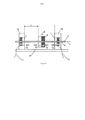
[0094] As figuras 4 e 5 mostram uma outra realização do dispositivo da presente invenção como um acionador magnético.[0094] Figures 4 and 5 show another embodiment of the device of the present invention as a magnetic driver.
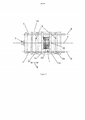
[0095] A figura 6 mostra uma outra realização do dispositivo magnético da presente invenção como um acionador magnético, que é similar à realização representada nas figuras 1 e 2.[0095] Figure 6 shows another embodiment of the magnetic device of the present invention as a magnetic driver, which is similar to the embodiment shown in Figures 1 and 2.
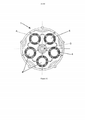
[0096] A figura 7 mostra uma outra realização do dispositivo magnético da presente invenção como um acionador magnético.[0096] Figure 7 shows another embodiment of the magnetic device of the present invention as a magnetic driver.
[0097] A figura 8 ilustra um possível acoplamento de vários acionadores magnéticos por meio de uma haste que é para ser acionada.[0097] Figure 8 illustrates a possible coupling of several magnetic actuators by means of a rod that is to be actuated.
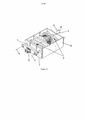
[0098] As figuras 9 a 11 mostram uma outra realização do dispositivo magnético da presente invenção como um acionador magnético.[0098] Figures 9 to 11 show another embodiment of the magnetic device of the present invention as a magnetic driver.
[0099] A figura 12 mostra uma outra realização do dispositivo magnético da presente invenção como um elemento de resistência.[0099] Figure 12 shows another embodiment of the magnetic device of the present invention as a resistance element.
[0100] A figura 13 mostra uma vista isométrica de uma outra realização do dispositivo magnético da presente inovação.[0100] Figure 13 shows an isometric view of another embodiment of the magnetic device of the present innovation.
[0101] A figura 14 mostra uma vista superior igual a uma vista inferior da realização mostrada na figura 13.[0101] Figure 14 shows a top view equal to a bottom view of the embodiment shown in figure 13.
[0102] A figura 15 mostra uma vista lateral transversal de uma realização da presente inovação dada nas figuras 13-14.[0102] Figure 15 shows a cross-sectional side view of an embodiment of the present innovation given in figures 13-14.
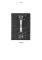
[0103] A figura 16 mostra o arranjo dos elementos usados na simulação do Método dos Elementos Finitos da realização dada nas figuras 13-15.[0103] Figure 16 shows the arrangement of the elements used in the Finite Element Method simulation of the realization given in figures 13-15.
[0104] As figuras 17-18 são referentes aos resultados da simulação do Método dos Elementos Finitos.[0104] Figures 17-18 refer to the results of the simulation of the Finite Element Method.
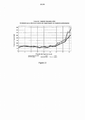
[0105] As figuras 19-20 mostram diagramas concernentes à simulação do Método dos Elementos Finitos.[0105] Figures 19-20 show diagrams concerning the simulation of the Finite Element Method.
[0106] As figuras 1 e 2 mostram uma realização do dispositivo magnético da presente invenção como um acionador magnético (20) e todas as variáveis usadas no relatório. O dispositivo magnético (20) compreende um translator (2) e estatores (1, 1’) que são dispostos lateralmente em relação ao translator (2). Os estatores (1, 1’) e o translator são eletromagnetos que são orientados ao longo do eixo - na realização exemplificadora mostrada nas figuras 1 e 2 ao longo do eixo motor do translator (3). O momento dipolar dos estatores (1, 1’) e do translator (2) é paralelo ao dito eixo.[0106] Figures 1 and 2 show an embodiment of the magnetic device of the present invention as a magnetic driver (20) and all variables used in the report. The magnetic device (20) comprises a translator (2) and stators (1, 1 ') which are arranged laterally in relation to the translator (2). The stators (1, 1 ') and the translator are electromagnets that are oriented along the axis - in the example shown in figures 1 and 2 along the driving axis of the translator (3). The dipole moment of the stators (1, 1 ') and the translator (2) is parallel to said axis.
[0107] Para sustentar uma polarização alternada do translator (2), o dito translator (2) é conectado a uma fonte de alimentação a.c. (não representada) por meio de um cabo de alimentação (11), enquanto cada um dos estatores (1, 1’) é conectado a um fonte d.c. (não representada) via cabos de alimentação adicionais (11).[0107] To support an alternating polarization of the translator (2), said translator (2) is connected to an a.c. (not shown) via a power cable (11), while each of the stators (1, 1 ’) is connected to a d.c. (not shown) via additional power cables (11).
[0108] A polarização do translator (2) é selecionada, de forma que o polo do translator (2) que está voltado para o estator esquerdo (1) é polarizado da mesma forma que o polo mais próximo do estator esquerdo (1), que ativa a força repulsiva (13) entre o estator esquerdo (1) e o translator (2); o polo do translator (2) que está voltado para o estator direito (1’) é polarizado diferentemente do polo mais próximo do estator direito (E), que ativa uma força atrativa (12) entre o estator direito (1’) e o translator (2). As forças atrativa (12) e repulsiva (13) atuam no translator (2) e causam uma força resultante em um deslocamento do translator (2) na direção de deslocamento do translator (6), conforme ilustrado na figura 1, do lado esquerdo para o direito, a direção de deslocamento do translator (6) sendo orientada no sentido do estator (E). O deslocamento do translator (2) na direção de deslocamento do translator (6) após ter alterado a polarização do translator (2) é representado na figura 2.[0108] The polarization of the translator (2) is selected, so that the pole of the translator (2) that faces the left stator (1) is polarized in the same way as the pole closest to the left stator (1), which activates the repulsive force (13) between the left stator (1) and the translator (2); the pole of the translator (2) facing the right stator (1 ') is polarized differently from the pole closest to the right stator (E), which activates an attractive force (12) between the right stator (1') and the translator (2). The attractive (12) and repulsive (13) forces act on the translator (2) and cause a force resulting in a displacement of the translator (2) in the direction of displacement of the translator (6), as shown in figure 1, on the left side for the right, the direction of travel of the translator (6) being oriented in the direction of the stator (E). The displacement of the translator (2) in the direction of travel of the translator (6) after having changed the polarization of the translator (2) is shown in figure 2.
[0109] Quando o acionador magnético (20) está em operação, o translator (2) sempre é posicionado em uma distância r maior do que zero em relação ao estator (1). Por meio desse aspecto (ver parte de caracterização da reivindicação 1) qualquer contato entre o translator (2) e um dos estatores (1, 1’) quando se opera o acionador magnético (20) da invenção pode ser excluído. A distância r é definida como a distância entre a extremidade do polo do translator (2) e a do respectivo estator (1, 1’) que estão de frente um para o outro.[0109] When the magnetic actuator (20) is in operation, the translator (2) is always positioned at a distance r greater than zero in relation to the stator (1). Through this aspect (see the characterization part of claim 1) any contact between the translator (2) and one of the stators (1, 1 ') when operating the magnetic driver (20) of the invention can be excluded. The distance r is defined as the distance between the end of the pole of the translator (2) and that of the respective stator (1, 1 ’) facing each other.
[0110] No caso de um deslocamento linear do translator (2) na direção de deslocamento do translator (6) para o lado esquerdo, o translator (2) atinge a posição (16). A posição (16) é uma posição final do deslocamento linear do translator (2) e é caracterizada pelo fato de a distância entre o translator (2) e o estator esquerdo (1) corresponder à menor distância definida r2, enquanto a distância entre o translator e o estator direito (1’) corresponde à maior distância definida n. As distâncias n e n são definidas de forma que, após a alteração da polarização do translator (2) para a realização de um deslocamento subsequente do translator (2) do lado direito para o lado esquerdo, conforme mostrado na figura 2, a força repulsiva gerada entre os polos de mesmo sinal do translator (2) e do estator esquerdo (1) é de uma magnitude máxima.[0110] In the case of a linear displacement of the translator (2) in the direction of travel of the translator (6) to the left side, the translator (2) reaches the position (16). Position (16) is a final position of the linear displacement of the translator (2) and is characterized by the fact that the distance between the translator (2) and the left stator (1) corresponds to the smallest defined distance r2, while the distance between the translator and the right stator (1 ') corresponds to the largest defined distance n. The nen distances are defined in such a way that, after changing the polarization of the translator (2) to perform a subsequent displacement of the translator (2) from the right side to the left side, as shown in figure 2, the repulsive force generated between the poles of the same signal from the translator (2) and the left stator (1) are of maximum magnitude.
[0111] A distância r é predefinida por uma unidade de controle, a dita unidade de controle alterando a polarização do translator (2) que é um eletromagneto. Se o translator atinge a posição (16), os polos do translator (2’) são alterados, assim o translator (2) é deslocado em uma direção de deslocamento oposta à direção de deslocamento ilustrada na figura 1. Alterando-se a polarização dos estatores (1, 1’), forças repulsivas são ativadas entre o translator (2) e o estator esquerdo, enquanto forças atrativas são ativadas entre o translator (2) e o estator direito (F), as ditas forças tendo um nível de energia definido, que levam o translator (2) a se deslocar do lado direito para o lado esquerdo, conforme ilustrado na figura 2.[0111] The distance r is predefined by a control unit, said control unit changing the polarization of the translator (2) which is an electromagnet. If the translator reaches position (16), the poles of the translator (2 ') are changed, so the translator (2) is moved in a direction of travel opposite to the direction of travel illustrated in figure 1. Changing the polarization of the stators (1, 1 '), repulsive forces are activated between the translator (2) and the left stator, while attractive forces are activated between the translator (2) and the right stator (F), said forces having an energy level defined, which cause the translator (2) to move from the right side to the left side, as shown in figure 2.
[0112] O estator (1) é suportado em um suporte de estator (14) por meio de uma construção de suporte (15).[0112] The stator (1) is supported on a stator support (14) by means of a support construction (15).
[0113] O translator (2) é acoplado a um eixo motor (3), que também serve como uma unidade guia (7) para o translator (2) na realização ilustrada na figura 1. O eixo guia (8) da unidade guia (7) é paralelo à direção de deslocamento do translator (6). O eixo guia (8) se estende através dos estatores (1, 1’) e do translator (2), os respectivos campos magnéticos dos estatores (1, 1’) e do translator (2) não sendo perturbados pela presença do eixo guia (8).[0113] The translator (2) is coupled to a driving shaft (3), which also serves as a guide unit (7) for the translator (2) in the embodiment shown in figure 1. The guide axis (8) of the guide unit (7) is parallel to the direction of travel of the translator (6). The guide axis (8) extends through the stators (1, 1 ') and the translator (2), the respective magnetic fields of the stators (1, 1') and the translator (2) are not disturbed by the presence of the guide axis (8).
[0114] O volume entre os estatores (1, 1’) é um vácuo. Para se obter o dito vácuo, o acionador magnético (20) é disposto no interior de uma armação (não representada).[0114] The volume between the stators (1, 1 ') is a vacuum. In order to obtain said vacuum, the magnetic actuator (20) is arranged inside a frame (not shown).
[0115] O gráfico revelado na figura 3a mostra a dependência da força repulsiva (13) entre o translator (2) e o estator esquerdo (1), quando o translator (2) se desloca conforme ilustrado na figura 1. Na figura 3a, assim como nas figuras 3b e 3c, a distância entre o translator e o respectivo estator (1, 1’) é indicado no eixo x, enquanto a força atuando entre o translator (2) e o estator (1, 1’) é indicada no eixo y. Os gráficos revelados nas figuras 3a, 3b e 3c constituem a base pra um cálculo baseado nas equações reveladas no relatório e nas seguintes suposições:
[0116] Em uma posição Xt = 0,04m, o translator (2) entraria em contato com o estator (1). O valor y do gráfico na figura 3a chega cada vez mais perto de alcançar zero. A força repulsiva (13) atinge o seu máximo em uma distância ε. A posição (16) do translator (2) é preferivelmente escolhida pela unidade guia de uma forma que o ponto zero do translator (2) é espaçada por uma distância εmin do ponto zero do estator adjacente (1, 1’).[0116] In a position Xt = 0.04m, the translator (2) would come in contact with the stator (1). The y-value of the graph in figure 3a comes closer and closer to reaching zero. The repulsive force (13) peaks at a distance ε. The position (16) of the translator (2) is preferably chosen by the guide unit in such a way that the zero point of the translator (2) is spaced a distance εmin from the zero point of the adjacent stator (1, 1 ').
[0117] O gráfico na figura 3b mostra a dependência da força atrativa (13) em relação à distância entre o translator (2) e o estator direito (1’) de acordo com a representação na figura 1. Geralmente, a força atrativa (13) aumenta quando o translator (2) se aproxima cada vez mais do estator direito (F).[0117] The graph in figure 3b shows the dependence of the attractive force (13) in relation to the distance between the translator (2) and the right stator (1 ') according to the representation in figure 1. Generally, the attractive force ( 13) increases when the translator (2) gets closer and closer to the right stator (F).
[0118] A figura 3c mostra o gráfico resultante dos gráficos nas figuras 3a e 3b. O gráfico na figura 3c mostra a condição de força resultante do desenvolvimento da força repulsiva (13) e da força atrativa (12), dependendo da posição do translator (2) entre os estatores (1, F), a condição de força resultante sendo paralela ao eixo, em referência às figuras 1 e 2 paralela ao eixo de deslocamento (3).[0118] Figure 3c shows the graph resulting from the graphs in figures 3a and 3b. The graph in figure 3c shows the force condition resulting from the development of the repulsive force (13) and the attractive force (12), depending on the position of the translator (2) between the stators (1, F), the resulting force condition being parallel to the axis, with reference to figures 1 and 2 parallel to the displacement axis (3).
[0119] As figuras 4 e 5 mostram uma outra realização do dispositivo magnético da invenção como um acionador magnético (20), a dita realização sendo similar àquela ilustrada nas figuras 1 e 2. Em contraste com a realização representada na figura 2, na dita realização adicional mostrada na figura 3, a polarização do translator (2) permanece a mesma durante o deslocamento do translator (2), enquanto a polarização de estatores (1, F) é alterada.[0119] Figures 4 and 5 show another embodiment of the magnetic device of the invention as a magnetic driver (20), said embodiment being similar to that illustrated in figures 1 and 2. In contrast to the embodiment shown in figure 2, in said additional realization shown in figure 3, the polarization of the translator (2) remains the same during the displacement of the translator (2), while the polarization of stators (1, F) is changed.
[0120] A figura 6 mostra uma realização similar à realização ilustrada na figura 4, a dita realização compreendendo duas unidades guia, em contraste com a realização mostrada na figura 4. O campo magnético atuando entre os estatores (1, F) e o translator (2) não é perturbado pela unidade guia (7), o que constitui uma vantagem em comparação à realização mostrada na figura 4.[0120] Figure 6 shows a realization similar to the realization illustrated in figure 4, said realization comprising two guide units, in contrast to the realization shown in figure 4. The magnetic field acting between the stators (1, F) and the translator (2) is not disturbed by the guide unit (7), which is an advantage compared to the realization shown in figure 4.
[0121] A figura 7 mostra uma outra realização do acionador magnético (20) da invenção, o deslocamento do translator (2) sendo giratório. O acionador magnético (20) compreende quatro magnetos translatores individuais (5), em forma de segmento, que são dispostos em um círculo (10) ao redor de um eixo motor (3) e de um eixo translator de rotação e em um ângulo certo em relação àquele. Os magnetos translatores individuais (5) são mecanicamente acoplados ao eixo motor (3) via unidades guia, de modo que os ditos magnetos translatores individuais (5) formem um translator (2). Nas áreas entre os magnetos translatores individuais (5), quatro magnetos estatores individuais (4), igualmente em forma de segmento, são dispostos, os ditos magnetos estatores individuais (4) sendo acoplados para formar um estator (1) por meio de um acoplamento mecânico (não representado).[0121] Figure 7 shows another embodiment of the magnetic driver (20) of the invention, the displacement of the translator (2) being rotatable. The magnetic drive (20) comprises four individual translator magnets (5), in the form of a segment, which are arranged in a circle (10) around a driving axis (3) and a rotating translator axis and at a right angle in relation to that. The individual translator magnets (5) are mechanically coupled to the drive shaft (3) via guide units, so that said individual translator magnets (5) form a translator (2). In the areas between the individual translator magnets (5), four individual magnet magnets (4), also in the form of a segment, are arranged, said individual magnet magnets (4) being coupled to form a stator (1) by means of a coupling mechanical (not shown).
[0122] De acordo com a divulgação acima, os polos dos magnetos estatores individuais (4) e dos magnetos translatores individuais (5) que estão de frente um para o outro são de mesmos ou de diferentes sinais.[0122] According to the above disclosure, the poles of the individual stator magnets (4) and of the individual translator magnets (5) that face each other are of the same or different signals.
[0123] Se o deslocamento do translator (2) é giratório, o translator estará sempre espaçado do estator quando o acionador magnético (20) estiver em operação, a direção do movimento giratório (6) de um magneto translator individual (5) será sempre orientado no sentido de um magneto estator individual (4).[0123] If the displacement of the translator (2) is rotatable, the translator will always be spaced from the stator when the magnetic actuator (20) is in operation, the direction of the rotational movement (6) of an individual translator magnet (5) will always be oriented towards an individual magnet stator (4).
[0124] A figura 8 mostra o acoplamento de um primeiro acionador magnético (20) da invenção a um outro acionador magnético (20’) da invenção. O acoplamento mecânico dos acionadores magnéticos (20, 20’) é obtido por meio de um disco (17) que é suportado para girar ao redor de um centro de disco (18). Por razões geométricas, uma haste (19) é provida entre o disco (17) e cada um dos acionadores magnéticos (20, 20’), uma extremidade da dita haste sendo conectada ao disco (17) em uma posição excêntrica em relação ao centro do disco (18), a sua outra extremidade sendo engrenada ao respectivo acionador magnético (20, 20’).[0124] Figure 8 shows the coupling of a first magnetic driver (20) of the invention to another magnetic driver (20 ') of the invention. The mechanical coupling of the magnetic actuators (20, 20 ') is obtained by means of a disc (17) which is supported to rotate around a disc center (18). For geometric reasons, a rod (19) is provided between the disc (17) and each of the magnetic actuators (20, 20 '), one end of said rod being connected to the disc (17) in an eccentric position in relation to the center of the disc (18), its other end being engaged with the respective magnetic driver (20, 20 ').
[0125] Os acionadores magnéticos (20, 20’) são montados em posições fixas em relação ao centro do disco (18), de forma que o deslocamento linear gerado pelos acionadores magnéticos (20, 20’) cria um movimento giratório do disco (17). Arranjando-se a haste (19, 19’) em uma posição excêntrica, o deslocamento linear do translator (2) (não mostrado na figura 8) do acionador magnético (20, 20’) é controlado mecanicamente.[0125] The magnetic actuators (20, 20 ') are mounted in fixed positions in relation to the center of the disk (18), so that the linear displacement generated by the magnetic actuators (20, 20') creates a rotating movement of the disk ( 17). By arranging the rod (19, 19 ') in an eccentric position, the linear displacement of the translator (2) (not shown in figure 8) of the magnetic driver (20, 20') is mechanically controlled.
[0126] As figuras 9 a 11 mostram vistas de uma realização do acionador magnético que é caracterizado por vários magnetos estatores individuais (4) sendo arranjados em um estator (1, 1’) e por vários magnetos translatores individuais (5) sendo arranjados no translator (2), e vistas detalhadas do translator (2) e do estator (1, 1’).[0126] Figures 9 to 11 show views of an embodiment of the magnetic drive that is characterized by several individual stator magnets (4) being arranged in a stator (1, 1 ') and by several individual translator magnets (5) being arranged in the translator (2), and detailed views of the translator (2) and the stator (1, 1 ').
[0127] A figura 9 mostra uma realização do acionador magnético ilustrado nas figuras 9 a 11, vista de cima. O acionador magnético compreende dois estatores (1, 1’) dispostos ao longo de um eixo (9). Além disso, duas unidades guia (7) são arranjadas, as ditas unidades guia (7) suportando o translator entre os estatores (1, 1’) de modo que ele possa ser deslocado em relação aos ditos estatores (1, 1’). O translator (2) é acoplado adicionalmente a um eixo motor (3) se estendendo através dos estatores (1, 1’) até um elemento acionador (não representado). A construção de suporte (15) também serve como um suporte para o eixo motor.[0127] Figure 9 shows an embodiment of the magnetic actuator illustrated in figures 9 to 11, seen from above. The magnetic drive comprises two stators (1, 1 ') arranged along an axis (9). In addition, two guide units (7) are arranged, said guide units (7) supporting the translator between the stators (1, 1 ') so that it can be displaced in relation to said stators (1, 1'). The translator (2) is additionally coupled to a driving shaft (3) extending through the stators (1, 1 ') to a driving element (not shown). The support construction (15) also serves as a support for the driving shaft.
[0128] A figura 10 mostra uma vista lateral do estator (1) da realização do acionador magnético da invenção mostrada nas figuras 9 a 11. O estator (1) compreende cinco magnetos estatores individuais (4) que são dispostos de forma rotacional e simétrica ao redor de um eixo motor (3). Cada um dos magnetos estatores individuais (4) é disposto do lado oposto dos magnetos translatores individuais (5).[0128] Figure 10 shows a side view of the stator (1) of the realization of the magnetic actuator of the invention shown in figures 9 to 11. The stator (1) comprises five individual stator magnets (4) which are arranged in a rotational and symmetrical way around a driving shaft (3). Each of the individual stator magnets (4) is disposed on the opposite side of the individual translator magnets (5).
[0129] A figura 11 mostra uma vista lateral do translator (2). O translator (2) compreende vários magnetos translatores individuais (5) que são dispostos de forma rotacional e simétrica ao redor do eixo motor (3), que é perpendicular à vista plana, ao longo de um polígono (10). Os magnetos translatores individuais (5), por um lado, estão dispostos no eixo motor e, por outro lado, em um suporte de translator (21) por meio de rolamentos de translator (22). Os rolamentos do translator (22) são redes, cada uma tendo uma área transversal tão pequena quanto possível.[0129] Figure 11 shows a side view of the translator (2). The translator (2) comprises several individual translator magnets (5) that are arranged in a rotational and symmetrical way around the driving axis (3), which is perpendicular to the plane view, along a polygon (10). The individual translator magnets (5), on the one hand, are arranged on the driving shaft and, on the other hand, on a translator support (21) by means of translator bearings (22). The bearings of the translator (22) are networks, each having a cross-sectional area as small as possible.
[0130] A figura 12 mostra uma outra realização do acionador magnético da invenção como um elemento de resistência. Basicamente, a construção é similar àquela das realizações descritas acima, os estatores (1, 1’), contudo, sendo polarizados em relação ao translator (2) de uma maneira que forças repulsivas (13) entre os polos do translator (2) e aquelas dos estatores (1, 1’) são ativadas. O translator (2) pode, assim, ser deslocado ao longo de uma distância entre os estatores (1, 1’), quando ele é acelerado por uma força atuando nele por meio do eixo motor (3).[0130] Figure 12 shows another embodiment of the magnetic actuator of the invention as a resistance element. Basically, the construction is similar to that of the realizations described above, the stators (1, 1 '), however, being polarized in relation to the translator (2) in a way that repulsive forces (13) between the poles of the translator (2) and those of the stators (1, 1 ') are activated. The translator (2) can thus be moved along a distance between the stators (1, 1 ’), when it is accelerated by a force acting on it through the motor axis (3).
[0131] A figura 13 mostra uma vista isométrica de uma realização do dispositivo magnético da invenção. O dispositivo magnético compreende um estator (1) disposto entre dois translatores (2), os ditos estator (1) e translatores (2) sendo dispostos no interior de uma estrutura de suporte (15) que forma uma armação. O eixo motor (3) é localizado do lado de fora da dita estrutura de suporte. O estator (1) e os translatores (2) são dispostos ao longo do eixo (9) que determina a direção (6) do deslocamento do translator.[0131] Figure 13 shows an isometric view of an embodiment of the magnetic device of the invention. The magnetic device comprises a stator (1) arranged between two translators (2), said stator (1) and translators (2) being arranged within a support structure (15) that forms a frame. The driving shaft (3) is located outside said support structure. The stator (1) and the translators (2) are arranged along the axis (9) that determines the direction (6) of the translator's displacement.
[0132] Os translatores (2) são montados em e suportados por duas unidades guia (7), os eixos guia (8) sendo orientados paralelamente à direção de deslocamento dos translatores (6). As unidades guia (8) são dispostas lateralmente em relação aos translatores (2) de forma que não interfiram no campo magnético entre os translatores (2) e os estatores (1).[0132] The translators (2) are mounted on and supported by two guide units (7), the guide axes (8) being oriented parallel to the direction of travel of the translators (6). The guide units (8) are arranged laterally in relation to the translators (2) so that they do not interfere in the magnetic field between the translators (2) and the stators (1).
[0133] As unidades guia (8) são suportadas pela estrutura de suporte (15). O dispositivo magnético mostrado na figura 13 possui essencialmente aquelas características acima mencionadas que sejam apropriadas. Os translatores (2) são magnetos de grau N45. O estator é um eletromagneto compreendendo um núcleo magnético (22) e uma bobina (23) enrolada em torno do dito núcleo (22).[0133] Guide units (8) are supported by the support structure (15). The magnetic device shown in figure 13 essentially has those characteristics mentioned above that are appropriate. The translators (2) are N45 grade magnets. The stator is an electromagnet comprising a magnetic core (22) and a coil (23) wound around said core (22).
[0134] A figura 14 mostra uma vista superior, correspondente a uma vista inferior, do dispositivo magnético da invenção mostrado na figura 13. As características do dispositivo descrito com referência à figura 13 podem ser vistas essencialmente na figura 14.[0134] Figure 14 shows a top view, corresponding to a bottom view, of the magnetic device of the invention shown in figure 13. The characteristics of the device described with reference to figure 13 can be seen essentially in figure 14.
[0135] Na figura 14, as posições dos translatores (2) e do estator (1) e do eixo motor (3) ao longo do eixo (9) podem ser vistas.[0135] In figure 14, the positions of the translators (2) and the stator (1) and the driving axis (3) along the axis (9) can be seen.
[0136] O estator (1) é montado na estrutura de suporte (15) por meio de um suporte de estator (14). O núcleo (22) do estator (1) se estende na direção do eixo (9), projetando-se a partir da estrutura de suporte (15), de modo que o campo magnético entre o estator (1) e os translatores (2) não seja interferido pelo suporte de estator (14).[0136] The stator (1) is mounted on the support structure (15) by means of a stator support (14). The stator core (22) extends in the direction of the axis (9), projecting from the support structure (15), so that the magnetic field between the stator (1) and the translators (2 ) is not interfered by the stator support (14).
[0137] O formato do suporte de translator (24), por meio do qual os translatores (2) são montados na unidade guia (7), é adaptado à tensão do momento, evidente para aqueles que são técnicos no assunto, e as forças de oscilação causadas, entre outras coisas, pelo movimento oscilatório dos translatores (2).[0137] The shape of the translator support (24), by means of which the translators (2) are mounted on the guide unit (7), is adapted to the current tension, evident for those who are technicians in the subject, and the forces oscillations caused, among other things, by the oscillatory movement of the translators (2).
[0138] A figura 15 mostra uma vista em corte do dispositivo magnético mostrado nas figuras 13 e 14. Em adição às características acima mencionadas, uma área de cálculo (21) pode ser vista; para essa área, uma curva de força de campo magnético foi determinada usando-se o Método dos Elementos Finitos (“Finite Elements Method” - FEM). Para tornar os cálculos mais fáceis, a área de cálculo (21) cobre apenas uma metade simétrica; o eixo de simetria na figura 15 corresponde ao eixo (9).[0138] Figure 15 shows a sectional view of the magnetic device shown in figures 13 and 14. In addition to the features mentioned above, a calculation area (21) can be seen; for this area, a magnetic field strength curve was determined using the Finite Elements Method (FEM). To make calculations easier, the calculation area (21) covers only a symmetrical half; the axis of symmetry in figure 15 corresponds to the axis (9).
[0138] Os resultados do cálculo pelo FEM (ver figuras 17 e 18) serão discutidos nos parágrafos abaixo.[0138] The results of the calculation by the FEM (see figures 17 and 18) will be discussed in the paragraphs below.
[0139] A figura 16 mostra uma vista detalhada da metade simétrica para a qual os cálculos pelo FEM foram realizadas. O eixo de simetria novamente corresponde ao eixo (9). As metades simétricas dos translatores podem ser vistas na figura 16.[0139] Figure 16 shows a detailed view of the symmetrical half for which the FEM calculations were performed. The axis of symmetry again corresponds to the axis (9). The symmetrical halves of the translators can be seen in figure 16.
[0140] O estator (1) compreende um núcleo (22) e uma bobina (23); de novo, as respectivas metades simétricas podem ser vistas.[0140] The stator (1) comprises a core (22) and a coil (23); again, the respective symmetrical halves can be seen.
[0141] Na figura 16, uma outra área de cálculo (21) é mostrada.[0141] In figure 16, another calculation area (21) is shown.
[0142] Nas figuras 17 e 18 os resultados da simulação pelo FEM são ilustrados. O cálculo pelo FEM é baseado na suposição de que o estator é um eletromagneto de 90 A e que os translatores (2) são magnetos permanentes de grau N45 de 1.050 kA/m.[0142] In figures 17 and 18 the results of the FEM simulation are illustrated. The calculation by FEM is based on the assumption that the stator is a 90 A electromagnet and that the translators (2) are permanent N45 grade magnets of 1,050 kA / m.
[0143] Na figura 17, a distância r entre a posição do translator (2) e do estator é de 1,00 mm. A força repulsiva (13) entre o estator (1) e o translator (2) constitui uma grande parte da força de translação atuando no translator (2), enquanto o deslocamento do translator (2’) é causado pela força atrativa (12) entre o translator (2’) e o estator (1).[0143] In figure 17, the distance r between the position of the translator (2) and the stator is 1.00 mm. The repulsive force (13) between the stator (1) and the translator (2) constitutes a large part of the translational force acting on the translator (2), while the displacement of the translator (2 ') is caused by the attractive force (12) between the translator (2 ') and the stator (1).
[0144] A figura 18 mostra os resultados da simulação pelo FEM quando os translatores (2) são posicionados em distâncias iguais em relação ao estator (1).[0144] Figure 18 shows the results of the FEM simulation when the translators (2) are positioned at equal distances from the stator (1).
[0145] A figura 19 mostra um gráfico que compara a força de translação medida no dispositivo de ensaio com a força de translação calculada com base em uma simulação pelo FEM. Em ambos os casos, os translatores contemplados foram magnetos permanentes de 1.050,0 kA/m. Para os cálculos, o estator foi provido com uma energia de 9 A, e os valores obtidos foram extrapolados para 90 A.[0145] Figure 19 shows a graph that compares the translation force measured in the test device with the translation force calculated based on a simulation by the FEM. In both cases, the contemplated translators were permanent magnets of 1,050.0 kA / m. For calculations, the stator was provided with an energy of 9 A, and the values obtained were extrapolated to 90 A.
[0146] O gráfico mostrado na figura 19 mostra claramente que a simulação baseada nas teorias discutidas acima e as medições são essencialmente consistentes.[0146] The graph shown in figure 19 clearly shows that the simulation based on the theories discussed above and the measurements are essentially consistent.
[0147] A figura 20 compara as forças de translação de translatores que são magnetos permanentes magnetizados diferentemente, as ditas forças de translação sendo calculadas por meio de uma simulação FEM baseada na teoria discutida acima. O eixo y do gráfico mostra os valores calculados da força de translação, enquanto o eixo x mostra a posição do translator. O gráfico na figura 20 mostra a influência da magnetização dos magnetos permanentes usados como translatores, quando os estatores são providos com uma energia de 9 A, extrapolada para 90 A. O gráfico inclui a curva “Força simulada [N]”, que mostra o comportamento geral das outras curvas. A curva “Força simulada [N]” também é incluída na figura 19.[0147] Figure 20 compares the translational forces of translators that are permanent magnets differently magnetized, said translational forces being calculated by means of an FEM simulation based on the theory discussed above. The y-axis of the graph shows the calculated values of the translational force, while the x-axis shows the position of the translator. The graph in figure 20 shows the influence of the magnetization of the permanent magnets used as translators, when the stators are provided with an energy of 9 A, extrapolated to 90 A. The graph includes the curve “Simulated force [N]”, which shows the general behavior of the other curves. The “Simulated Force [N]” curve is also included in figure 19.
Claims (8)


Applications Claiming Priority (3)
| Application Number | Priority Date | Filing Date | Title |
|---|---|---|---|
| ATA1260/2011 | 2011-09-05 | ||
| ATA1260/2011A AT510941B1 (en) | 2011-09-05 | 2011-09-05 | MAGNETIC DEVICE |
| PCT/EP2012/063713 WO2013034339A2 (en) | 2011-09-05 | 2012-07-12 | Magnet device |
Publications (2)
| Publication Number | Publication Date |
|---|---|
| BR112014005056A2 BR112014005056A2 (en) | 2017-05-16 |
| BR112014005056B1 true BR112014005056B1 (en) | 2020-11-03 |
Family
ID=46750036
Family Applications (1)
| Application Number | Title | Priority Date | Filing Date |
|---|---|---|---|
| BR112014005056-2A BR112014005056B1 (en) | 2011-09-05 | 2012-07-12 | magnetic device |
Country Status (14)
| Country | Link |
|---|---|
| US (1) | US8952578B2 (en) |
| EP (1) | EP2754159B1 (en) |
| JP (1) | JP6213782B2 (en) |
| KR (1) | KR101898102B1 (en) |
| CN (1) | CN103946932B (en) |
| AR (1) | AR087783A1 (en) |
| AT (1) | AT510941B1 (en) |
| BR (1) | BR112014005056B1 (en) |
| EA (1) | EA034418B1 (en) |
| IL (1) | IL231315A0 (en) |
| MX (1) | MX2014002607A (en) |
| TW (1) | TWI578666B (en) |
| WO (1) | WO2013034339A2 (en) |
| ZA (1) | ZA201402175B (en) |
Families Citing this family (5)
| Publication number | Priority date | Publication date | Assignee | Title |
|---|---|---|---|---|
| WO2015047938A1 (en) * | 2013-09-26 | 2015-04-02 | Means Industries, Inc. | Electromagnetic system for overrunning coupling assembly |
| EP2998801A1 (en) * | 2014-09-19 | 2016-03-23 | The Swatch Group Research and Development Ltd. | Magnetic clock escapement and device for controlling the operation of a clock movement |
| DE102014214439A1 (en) * | 2014-07-23 | 2016-01-28 | Micro-Epsilon Messtechnik Gmbh & Co. Kg | Actuator-sensor assembly and method of use in such an arrangement |
| AT515114B1 (en) | 2014-09-23 | 2015-06-15 | Seh Ltd | Magnetic device comprising stators and translators |
| FR3064764B1 (en) * | 2017-03-28 | 2019-06-28 | Hutchinson | DYNAMIC EFFORTS GENERATOR COMPRISING AT LEAST TWO BALOURS AND ACTUATOR COMPRISING SUCH GENERATORS |
Family Cites Families (35)
| Publication number | Priority date | Publication date | Assignee | Title |
|---|---|---|---|---|
| US3238397A (en) * | 1963-01-21 | 1966-03-01 | Norman B Maness | Electrical reciprocation apparatus |
| GB1392010A (en) * | 1972-08-18 | 1975-04-23 | Bell Punch Co Ltd | Printing machines |
| JPS5633620A (en) * | 1979-08-28 | 1981-04-04 | Canon Inc | Light scanner |
| JPS5731367A (en) * | 1980-08-01 | 1982-02-19 | Sumitomo Heavy Ind Ltd | Linear motion vs. electric energy converter |
| JPS5913084U (en) * | 1982-07-16 | 1984-01-26 | ミサワホ−ム株式会社 | Electromagnetic reciprocating device |
| US5166563A (en) * | 1990-03-02 | 1992-11-24 | Stuart Bassine | Magnetically actuated linear displacement compressor |
| US5203172A (en) * | 1990-05-17 | 1993-04-20 | Simpson Alvin B | Electromagnetically powered hydraulic engine |
| JPH04117157A (en) * | 1990-05-25 | 1992-04-17 | Sony Corp | Voice coil type actuator |
| US5175455A (en) * | 1990-10-31 | 1992-12-29 | Otis Elevator Company | Permanent magnet linear door motor |
| EP0580117A3 (en) * | 1992-07-20 | 1994-08-24 | Tdk Corp | Moving magnet-type actuator |
| JP3371041B2 (en) * | 1994-11-02 | 2003-01-27 | 住友特殊金属株式会社 | Magnet movable linear actuator |
| JP3341696B2 (en) * | 1998-02-16 | 2002-11-05 | 株式会社村田製作所 | Linear actuator |
| US6657847B1 (en) * | 1999-07-13 | 2003-12-02 | Siemens Automotive Corporation | Method of using inductance for determining the position of an armature in an electromagnetic solenoid |
| DE10003928A1 (en) * | 1999-11-25 | 2001-06-07 | Daimler Chrysler Ag | Electromagnetic actuator to operate gas change valve of internal combustion engine; has electromagnets and spring mechanism to adjust valve connected to armature between two end positions |
| JP3791402B2 (en) * | 2001-01-26 | 2006-06-28 | 松下電工株式会社 | Drive control method and drive control apparatus for linear vibration motor |
| JP2002335662A (en) * | 2001-05-10 | 2002-11-22 | Act Giken:Kk | Tristable self-holding magnet |
| DE10207828B4 (en) * | 2002-02-25 | 2004-10-07 | Technische Universität Dresden | Electromagnetic solenoid |
| JP2003339188A (en) * | 2002-05-21 | 2003-11-28 | Matsushita Electric Ind Co Ltd | Linear motor drive apparatus |
| JP2005245047A (en) * | 2004-02-24 | 2005-09-08 | Nippon Pulse Motor Co Ltd | Linear actuator |
| JP4725910B2 (en) * | 2004-09-07 | 2011-07-13 | 日本パルスモーター株式会社 | Linear actuator |
| JP2006121856A (en) * | 2004-10-25 | 2006-05-11 | Mitsubishi Electric Corp | Electromagnetic actuator |
| JP2006325381A (en) * | 2005-05-18 | 2006-11-30 | Mutsuo Hirano | Reciprocating linear engine |
| JP5092206B2 (en) * | 2005-06-09 | 2012-12-05 | シンフォニアテクノロジー株式会社 | Linear actuator positioning control method and apparatus |
| WO2007034195A1 (en) * | 2005-09-21 | 2007-03-29 | Ricardo Uk Ltd. | Linear actuator |
| FR2894377B1 (en) * | 2005-12-02 | 2008-05-16 | Valeo Sys Controle Moteur Sas | ELECTROMAGNETIC ACTUATOR WITH TWO ELECTRO-MAGNETS COMPRISING MAGNETS OF DIFFERENT FORCES, AND METHOD OF MANAGING AN INTERNAL COMBUSTION ENGINE VALVE USING THE SAME. |
| JP2008206356A (en) * | 2007-02-22 | 2008-09-04 | Jtekt Corp | Moving magnet linear actuator |
| JP2009022087A (en) * | 2007-07-11 | 2009-01-29 | Sharp Corp | Linear motor, and stirling freezer equipped with the same |
| JP2010019934A (en) * | 2008-07-08 | 2010-01-28 | Seiko Epson Corp | Actuator, optical scanner and image forming apparatus |
| US7705493B2 (en) * | 2008-08-01 | 2010-04-27 | Van Os Ron | Magnetic mirror air bearing for Michelson interferometer with lateral motion |
| JP2010104078A (en) * | 2008-10-21 | 2010-05-06 | Jtekt Corp | Linear actuator |
| JP5396400B2 (en) * | 2008-11-17 | 2014-01-22 | コマツ産機株式会社 | Linear actuator |
| RO126256A2 (en) * | 2009-06-30 | 2011-04-29 | Ciprian Astratini-Enache | Miniature short stroke actuator with permanent magnets |
| JP2011062032A (en) * | 2009-09-14 | 2011-03-24 | Honda Motor Co Ltd | Linear servo actuator mechanism |
| DE202009014192U1 (en) * | 2009-10-20 | 2011-03-03 | Eto Magnetic Gmbh | Monostable electromagnetic actuator device |
| JP3158466U (en) * | 2010-01-18 | 2010-04-02 | 登冠科技股▲ふん▼有限公司 | Ultra-compact power generator |
-
2011
- 2011-09-05 AT ATA1260/2011A patent/AT510941B1/en not_active IP Right Cessation
-
2012
- 2012-07-12 EP EP12756120.7A patent/EP2754159B1/en active Active
- 2012-07-12 WO PCT/EP2012/063713 patent/WO2013034339A2/en active Application Filing
- 2012-07-12 EA EA201490572A patent/EA034418B1/en not_active IP Right Cessation
- 2012-07-12 JP JP2014527545A patent/JP6213782B2/en active Active
- 2012-07-12 MX MX2014002607A patent/MX2014002607A/en active IP Right Grant
- 2012-07-12 KR KR1020147009188A patent/KR101898102B1/en active IP Right Grant
- 2012-07-12 CN CN201280054289.4A patent/CN103946932B/en active Active
- 2012-07-12 BR BR112014005056-2A patent/BR112014005056B1/en active IP Right Grant
- 2012-08-31 US US13/600,709 patent/US8952578B2/en active Active
- 2012-09-04 TW TW101132166A patent/TWI578666B/en active
- 2012-09-05 AR ARP120103271A patent/AR087783A1/en unknown
-
2014
- 2014-03-05 IL IL231315A patent/IL231315A0/en active IP Right Grant
- 2014-03-25 ZA ZA2014/02175A patent/ZA201402175B/en unknown
Also Published As
| Publication number | Publication date |
|---|---|
| WO2013034339A3 (en) | 2013-09-06 |
| US20130057086A1 (en) | 2013-03-07 |
| TW201325036A (en) | 2013-06-16 |
| EA034418B1 (en) | 2020-02-05 |
| TWI578666B (en) | 2017-04-11 |
| AT510941A4 (en) | 2012-07-15 |
| CN103946932B (en) | 2016-10-12 |
| KR101898102B1 (en) | 2018-09-12 |
| WO2013034339A2 (en) | 2013-03-14 |
| EP2754159A2 (en) | 2014-07-16 |
| AT510941B1 (en) | 2012-07-15 |
| MX2014002607A (en) | 2014-07-24 |
| US8952578B2 (en) | 2015-02-10 |
| EP2754159B1 (en) | 2019-01-02 |
| AR087783A1 (en) | 2014-04-16 |
| JP6213782B2 (en) | 2017-10-18 |
| ZA201402175B (en) | 2016-01-27 |
| CN103946932A (en) | 2014-07-23 |
| IL231315A0 (en) | 2014-04-30 |
| KR20140072086A (en) | 2014-06-12 |
| BR112014005056A2 (en) | 2017-05-16 |
| EA201490572A1 (en) | 2014-08-29 |
| JP2014528230A (en) | 2014-10-23 |
Similar Documents
| Publication | Publication Date | Title |
|---|---|---|
| BR112014005056B1 (en) | magnetic device | |
| KR101308317B1 (en) | Electric motor which serves as power generator also using coil plate having devided coil and reciprocating sliding plate having devided magnet | |
| US10230292B2 (en) | Permanent magnet operating machine | |
| KR102498082B1 (en) | Electromechanical actuators and improvements therewith | |
| JP6367924B2 (en) | Scanner device | |
| Tsai et al. | Design and analysis of magnetically-drive actuator applied for linear compressor | |
| BRPI0716949A2 (en) | ELECTROMAGNETIC MACHINE | |
| BR112013009476B1 (en) | ELECTRIC MOTOR PAIRING AND METHOD FOR PRODUCING A MOTOR MECHANISM COURSE CYCLE | |
| TW201725314A (en) | Fluid electricity generation device with dual-housing and rotor assembly | |
| US20120242174A1 (en) | Hybrid Electro-Magnetic Reciprocating Motor | |
| BR112015015004B1 (en) | MAGNETIC DEVICE COMPRISING AN ACCELERATION UNIT THAT ACT ON THE TRANSFERER | |
| JP6135944B2 (en) | Magnetic device | |
| RU2550793C1 (en) | Controlled magneto-liquid shock absorber | |
| KR100953385B1 (en) | Device for generating stiffness using complex application of PM-type and VCM-type, and joint of robot manipulator comprising the same | |
| GB2533943A (en) | Improvements in and relating to electromechanical actuators | |
| RU2488936C1 (en) | Cylindrical linear induction motor | |
| RU2343491C2 (en) | Magnetic damper | |
| SU917270A1 (en) | Oscillatory motion electromagnetic motor | |
| RU142162U1 (en) | ELECTROMAGNETIC MOTOR | |
| RU142163U1 (en) | ELECTROMAGNETIC MOTOR | |
| KR102486934B1 (en) | Rotor for motor | |
| EP3043087A1 (en) | Improvements in and relating to electromechanical actuators | |
| RU2537103C2 (en) | Vibration unit | |
| Schuck et al. | Analysis and design of a passive electrodynamic bearing for an ultra-high speed spinning ball motor | |
| BR102013018837B1 (en) | VIBRATION SINK ELECTROMAGNETIC DEVICE FOR ROTARY SYSTEMS |
Legal Events
| Date | Code | Title | Description |
|---|---|---|---|
| B08F | Application dismissed because of non-payment of annual fees [chapter 8.6 patent gazette] | ||
| B08G | Application fees: restoration [chapter 8.7 patent gazette] | ||
| B06F | Objections, documents and/or translations needed after an examination request according [chapter 6.6 patent gazette] | ||
| B06U | Preliminary requirement: requests with searches performed by other patent offices: procedure suspended [chapter 6.21 patent gazette] | ||
| B09A | Decision: intention to grant [chapter 9.1 patent gazette] | ||
| B16A | Patent or certificate of addition of invention granted [chapter 16.1 patent gazette] |
Free format text: PRAZO DE VALIDADE: 20 (VINTE) ANOS CONTADOS A PARTIR DE 12/07/2012, OBSERVADAS AS CONDICOES LEGAIS. |