BR112014004045B1 - cover for an architectural opening - Google Patents
cover for an architectural opening Download PDFInfo
- Publication number
- BR112014004045B1 BR112014004045B1 BR112014004045-1A BR112014004045A BR112014004045B1 BR 112014004045 B1 BR112014004045 B1 BR 112014004045B1 BR 112014004045 A BR112014004045 A BR 112014004045A BR 112014004045 B1 BR112014004045 B1 BR 112014004045B1
- Authority
- BR
- Brazil
- Prior art keywords
- cell
- light
- absorbing element
- interface
- cover
- Prior art date
Links
Images


Classifications
-
- E—FIXED CONSTRUCTIONS
- E06—DOORS, WINDOWS, SHUTTERS, OR ROLLER BLINDS IN GENERAL; LADDERS
- E06B—FIXED OR MOVABLE CLOSURES FOR OPENINGS IN BUILDINGS, VEHICLES, FENCES OR LIKE ENCLOSURES IN GENERAL, e.g. DOORS, WINDOWS, BLINDS, GATES
- E06B9/00—Screening or protective devices for wall or similar openings, with or without operating or securing mechanisms; Closures of similar construction
- E06B9/24—Screens or other constructions affording protection against light, especially against sunshine; Similar screens for privacy or appearance; Slat blinds
- E06B9/26—Lamellar or like blinds, e.g. venetian blinds
- E06B9/262—Lamellar or like blinds, e.g. venetian blinds with flexibly-interconnected horizontal or vertical strips; Concertina blinds, i.e. upwardly folding flexible screens
-
- E—FIXED CONSTRUCTIONS
- E06—DOORS, WINDOWS, SHUTTERS, OR ROLLER BLINDS IN GENERAL; LADDERS
- E06B—FIXED OR MOVABLE CLOSURES FOR OPENINGS IN BUILDINGS, VEHICLES, FENCES OR LIKE ENCLOSURES IN GENERAL, e.g. DOORS, WINDOWS, BLINDS, GATES
- E06B9/00—Screening or protective devices for wall or similar openings, with or without operating or securing mechanisms; Closures of similar construction
- E06B9/24—Screens or other constructions affording protection against light, especially against sunshine; Similar screens for privacy or appearance; Slat blinds
- E06B9/26—Lamellar or like blinds, e.g. venetian blinds
- E06B9/38—Other details
- E06B9/386—Details of lamellae
-
- G—PHYSICS
- G02—OPTICS
- G02B—OPTICAL ELEMENTS, SYSTEMS OR APPARATUS
- G02B5/00—Optical elements other than lenses
- G02B5/20—Filters
- G02B5/22—Absorbing filters
-
- E—FIXED CONSTRUCTIONS
- E06—DOORS, WINDOWS, SHUTTERS, OR ROLLER BLINDS IN GENERAL; LADDERS
- E06B—FIXED OR MOVABLE CLOSURES FOR OPENINGS IN BUILDINGS, VEHICLES, FENCES OR LIKE ENCLOSURES IN GENERAL, e.g. DOORS, WINDOWS, BLINDS, GATES
- E06B9/00—Screening or protective devices for wall or similar openings, with or without operating or securing mechanisms; Closures of similar construction
- E06B9/24—Screens or other constructions affording protection against light, especially against sunshine; Similar screens for privacy or appearance; Slat blinds
- E06B2009/2405—Areas of differing opacity for light transmission control
-
- E—FIXED CONSTRUCTIONS
- E06—DOORS, WINDOWS, SHUTTERS, OR ROLLER BLINDS IN GENERAL; LADDERS
- E06B—FIXED OR MOVABLE CLOSURES FOR OPENINGS IN BUILDINGS, VEHICLES, FENCES OR LIKE ENCLOSURES IN GENERAL, e.g. DOORS, WINDOWS, BLINDS, GATES
- E06B9/00—Screening or protective devices for wall or similar openings, with or without operating or securing mechanisms; Closures of similar construction
- E06B9/24—Screens or other constructions affording protection against light, especially against sunshine; Similar screens for privacy or appearance; Slat blinds
- E06B9/26—Lamellar or like blinds, e.g. venetian blinds
- E06B9/262—Lamellar or like blinds, e.g. venetian blinds with flexibly-interconnected horizontal or vertical strips; Concertina blinds, i.e. upwardly folding flexible screens
- E06B2009/2627—Cellular screens, e.g. box or honeycomb-like
Landscapes
- Engineering & Computer Science (AREA)
- Structural Engineering (AREA)
- Architecture (AREA)
- Civil Engineering (AREA)
- Physics & Mathematics (AREA)
- Optics & Photonics (AREA)
- General Physics & Mathematics (AREA)
- Blinds (AREA)
- Building Environments (AREA)
- Securing Of Glass Panes Or The Like (AREA)
- Finishing Walls (AREA)
- Optical Filters (AREA)
- Optical Elements Other Than Lenses (AREA)
- Laminated Bodies (AREA)
- Roof Covering Using Slabs Or Stiff Sheets (AREA)
Abstract
COBERTURA PARA UMA ABERTURA ARQUITETÔNICA E PAINEL CELULAR PARA COBRIR UMA ABERTURA ARQUITETÔNICA. A presente invenção refere-se a uma cobertura (10) para uma abertura arquitetônica. A cobertura inclui um painel celular tendo pelo menos duas unidades celulares (22) ou fileiras. A cobertura também inclui um elemento absorvente de luz posicionado na interface entre as pelo menos duas unidades celulares (22). O primeiro elemento absorvente de luz pode absorver substancialmente todos os comprimentos de onda de luz visível.COVERAGE FOR AN ARCHITECTURAL OPENING AND CELLULAR PANEL TO COVER AN ARCHITECTURAL OPENING. The present invention relates to a cover (10) for an architectural opening. The cover includes a cell panel having at least two cell units (22) or rows. The cover also includes a light-absorbing element positioned at the interface between the at least two cell units (22). The first light absorbing element can absorb substantially all wavelengths of visible light.
Description
[001] Esse pedido reivindica o benefício sob 35 U.S.C. 119(e) do Pedido Provisório U.S. No. 61/528.028, depositado em 26 de agosto de 2011, que é incorporado, com isso, por referência aqui na sua íntegra.[001] This claim claims the benefit under 35 U.S.C. 119 (e) of U.S. Provisional Application No. 61 / 528,028, filed on August 26, 2011, which is hereby incorporated by reference here in its entirety.
[002] A presente invenção refere-se, de forma geral, a coberturas para aberturas arquitetônicas e, mais especificamente, para coberturas celulares para aberturas arquitetônicas.[002] The present invention relates, in general, to covers for architectural openings and, more specifically, for cellular covers for architectural openings.
[003] Coberturas para aberturas arquitetônicas, tais como janelas, portas, arcadas e assim por diante, adotaram várias formas por muitos anos com algumas dessas coberturas sendo retráteis por natureza de modo a ser móveis entre uma posição estendida através da abertura e uma posição retraída adjacente a um ou mais lados da abertura.[003] Covers for architectural openings, such as windows, doors, arcades and so on, have taken various forms for many years with some of these covers being retractable in nature so as to be movable between an extended position through the opening and a retracted position adjacent to one or more sides of the opening.
[004] Mais recentemente, coberturas retráteis foram feitas em um formato celular. As células em tais coberturas são tipicamente tubos alongados ou células que se estendem lateralmente através de uma abertura. Quando a cobertura está aberta e estendida através da abertura de uma janela, as próprias células são expandidas, mas quando a cobertura está retraída, as células fecham, de modo que cada célula fica empilhada com a célula adjacente e coletivamente ficam empilhadas juntas em um pequeno espaço.[004] More recently, retractable covers have been made in a cellular format. The cells in such covers are typically elongated tubes or cells that extend laterally through an opening. When the cover is open and extended through the opening of a window, the cells themselves are expanded, but when the cover is retracted, the cells close, so that each cell is stacked with the adjacent cell and collectively they are stacked together in a small space.
[005] Exemplos da revelação incluem uma cobertura para uma abertura arquitetônica. A cobertura inclui um painel celular tendo pelo menos duas unidades celulares ou fileiras empilhadas uma em cima da outra. A cobertura também inclui um primeiro elemento absorvente de luz posicionado em uma interface entre as pelo menos duas unidades celulares. O primeiro elemento absorvente de luz pode absorver substancialmente todos os comprimentos de onda de luz visível. Cada unidade celular pode incluir uma célula externa e uma célula interna pelo menos parcialmente recebida dentro da célula externa. Pelo menos uma porção da superfície externa da célula interna pode ficar exposta na interface, tal que a célula externa de outra unidade celular é posicionada adjacente à porção exposta da célula interna. O primeiro elemento absorvente de luz pode ser posicionado na célula interna ou na célula externa. Em uma configuração, o primeiro elemento absorvente de luz é posicionado em uma superfície externa da célula interna exposta em uma interface entre unidades celulares adjacentes. A cobertura pode ainda incluir um segundo elemento absorvente de luz posicionado em um lado oposto da interface do primeiro elemento absorvente de luz.[005] Examples of the revelation include a cover for an architectural opening. The cover includes a cell panel having at least two cell units or rows stacked on top of each other. The cover also includes a first light-absorbing element positioned at an interface between the at least two cell units. The first light absorbing element can absorb substantially all wavelengths of visible light. Each cell unit can include an outer cell and an inner cell at least partially received within the outer cell. At least a portion of the outer surface of the inner cell may be exposed at the interface, such that the outer cell of another cell unit is positioned adjacent to the exposed portion of the inner cell. The first light-absorbing element can be positioned in the inner or outer cell. In one configuration, the first light-absorbing element is positioned on an outer surface of the exposed inner cell at an interface between adjacent cell units. The cover may further include a second light-absorbing element positioned on an opposite side of the interface of the first light-absorbing element.
[006] Outros exemplos da revelação incluem um painel celular para cobrir uma abertura arquitetônica. O painel celular inclui uma primeira fileira celular e uma segunda fileira celular conectada operativamente na primeira fileira celular. A primeira fileira celular inclui uma primeira célula externa e uma primeira célula interna pelo menos parcialmente recebida dentro da primeira célula externa. Similarmente, a segunda fileira celular inclui uma segunda célula externa e uma segunda célula interna pelo menos parcialmente recebida dentro da segunda célula externa. A primeira célula interna e a segunda célula interna podem ser de um material absortivo de luz. O painel celular também inclui um primeiro elemento absorvente de luz posicionado em uma interface entre a primeira fileira celular e a segunda fileira celular. O primeiro elemento absorvente de luz pode ser posicionado em uma superfície externa da segunda célula interna, e a primeira célula externa pode definir um vão através do qual o primeiro elemento absorvente de luz fica exposto. Adicional ou alternativamente, o primeiro elemento absorvente de luz pode ser posicionado adjacente a uma primeira borda longitudinal da primeira célula interna. Em algumas configurações, o painel celular inclui uma terceira fileira celular conectada operativamente na segunda fileira celular e um segundo elemento absorvente de luz posicionado adjacente a uma interface entre a segunda fileira celular e a terceira fileira celular. Nessas configurações, o primeiro e o segundo elementos absorventes de luz podem ter larguras diferentes. Por exemplo, o segundo elemento absorvente de luz pode ter uma largura menor do que o primeiro elemento absorvente de luz.[006] Other examples of the revelation include a cell panel to cover an architectural opening. The cell panel includes a first cell row and a second cell row operatively connected to the first cell row. The first cell row includes a first outer cell and a first inner cell at least partially received within the first outer cell. Similarly, the second cell row includes a second outer cell and a second inner cell at least partially received within the second outer cell. The first inner cell and the second inner cell can be made of a light-absorbing material. The cell panel also includes a first light-absorbing element positioned at an interface between the first cell row and the second cell row. The first light-absorbing element can be positioned on an outer surface of the second inner cell, and the first outer cell can define a gap through which the first light-absorbing element is exposed. Additionally or alternatively, the first light absorbing element can be positioned adjacent a first longitudinal edge of the first inner cell. In some configurations, the cell panel includes a third cell row operatively connected to the second cell row and a second light absorbing element positioned adjacent an interface between the second cell row and the third cell row. In these configurations, the first and second light-absorbing elements may have different widths. For example, the second light-absorbing element may have a smaller width than the first light-absorbing element.
[007] Ainda outros exemplos da revelação incluem uma cobertura para uma abertura arquitetônica. A cobertura inclui um trilho principal, um painel celular e um trilho inferior. O painel celular é conectado operativamente no trilho principal e inclui pelo menos duas unidades celulares. Cada unidade celular do painel inclui uma célula externa e uma célula interna pelo menos parcialmente recebida dentro da célula externa. O painel celular ainda inclui um primeiro elemento absorvente de luz posicionado em uma interface entre as pelo menos duas unidades celulares. Além do mais, o trilho inferior é conectado operativamente em uma extremidade oposta do painel celular do trilho principal e se move verticalmente à medida que a cobertura se move entre uma posição estendida e uma posição retraída. O primeiro elemento absorvente de luz pode ser embutido em pelo menos uma da célula interna ou da célula externa e absorver substancialmente todo o comprimento de onda de luz visível. O primeiro elemento absorvente de luz pode ser Mylar tingido que absorve substancialmente todo o comprimento de onda de luz. Em algumas configurações, pelo menos uma porção da superfície externa da célula interna pode ficar exposta em uma interface entre unidades celulares adjacentes, tal que a célula externa de outra unidade celular fica posicionada adjacente à célula interna. Nessas configurações, o primeiro elemento absorvente de luz pode ser posicionado na célula interna e o elemento pode ainda ser posicionado na porção da superfície externa da célula interna que fica exposta na interface.[007] Still other examples of the revelation include a cover for an architectural opening. The cover includes a main rail, a cell panel and a bottom rail. The cell panel is operatively connected to the main rail and includes at least two cell units. Each cell unit of the panel includes an external cell and an internal cell at least partially received within the external cell. The cell panel further includes a first light-absorbing element positioned at an interface between the at least two cell units. In addition, the bottom rail is operatively connected at an opposite end of the main rail cell panel and moves vertically as the cover moves between an extended position and a retracted position. The first light-absorbing element can be embedded in at least one of the inner or outer cell and absorb substantially the entire wavelength of visible light. The first light-absorbing element can be dyed Mylar which absorbs substantially the entire wavelength of light. In some configurations, at least a portion of the outer surface of the inner cell may be exposed at an interface between adjacent cell units, such that the outer cell of another cell unit is positioned adjacent to the inner cell. In these configurations, the first light-absorbing element can be positioned in the inner cell and the element can also be positioned in the portion of the outer surface of the inner cell that is exposed at the interface.
[008] Esse sumário da revelação é apresentado para ajudar no entendimento e um versado na técnica entenderá que cada um dos vários aspectos e recursos da revelação pode ser usado vantajosamente de forma separada em alguns casos ou em combinação com outros aspectos e recursos da revelação em outros casos.[008] This summary of the disclosure is presented to aid understanding and one skilled in the art will understand that each of the various aspects and features of the disclosure can be used advantageously separately in some cases or in combination with other aspects and features of the disclosure in other cases.
[009] A Fig. 1A é uma vista isométrica de uma cobertura para uma abertura arquitetônica.[009] Fig. 1A is an isometric view of a roof for an architectural opening.
[0010] A Fig. 1B é uma vista isométrica da cobertura da Fig. 1A em uma posição retraída.[0010] Fig. 1B is an isometric view of the cover of Fig. 1A in a retracted position.
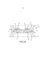
[0011] A Fig. 2A é uma vista em projeção lateral ampliada de uma interface entre unidades celulares adjacentes de um painel celular.[0011] Fig. 2A is an enlarged side projection view of an interface between adjacent cell units of a cell panel.
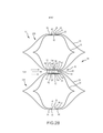
[0012] A Fig. 2B é uma vista em projeção lateral ampliada de um painel celular incluindo um elemento absorvente de luz.[0012] Fig. 2B is an enlarged side view of a cell panel including a light-absorbing element.
[0013] A Fig. 2C é uma vista em projeção lateral ampliada do painel celular da Fig. 2B com um elemento absorvente de luz embutido em uma parede da célula.[0013] Fig. 2C is an enlarged side view of the cellular panel of Fig. 2B with a light absorbing element embedded in a cell wall.
[0014] A Fig- 3 é uma vista em projeção lateral ampliada tomada ao longo da linha 3-3 da Fig. 1A.[0014] Fig-3 is an enlarged side projection view taken along line 3-3 of Fig. 1A.
[0015] A Fig- 4A é uma vista isométrica explodida ilustrando um exemplo de uma unidade celular.[0015] Fig-4A is an exploded isometric view illustrating an example of a cell unit.
[0016] A Fig- 4B é uma vista isométrica ampliada de uma unidade celular conectada operativamente em uma segunda unidade celular.[0016] Fig-4B is an enlarged isometric view of a cell unit operatively connected in a second cell unit.
[0017] A Fig. 5 é uma vista em projeção lateral de uma unidade celular.[0017] Fig. 5 is a side view of a cell unit.
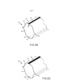
[0018] A Fig. 5A é uma vista isométrica superior de um exemplo de uma célula interna.[0018] Fig. 5A is a top isometric view of an example of an internal cell.
[0019] A Fig. 5B é uma vista isométrica inferior da célula interna da Fig. 5A.[0019] Fig. 5B is a lower isometric view of the inner cell of Fig. 5A.
[0020] A figura 5C é uma vista isométrica superior de outro exemplo de uma célula interna.[0020] Figure 5C is a top isometric view of another example of an internal cell.
[0021] A figura 6 é uma vista isométrica ampliada de outro exemplo de uma unidade celular conectada operativamente em uma segunda unidade celular.[0021] Figure 6 is an enlarged isometric view of another example of a cell unit operatively connected in a second cell unit.
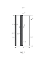
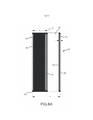
[0022] A figura 7 é uma vista plana superior de uma célula interna não formada exemplar incluindo dois elementos absorventes de luz.[0022] Figure 7 is a top plan view of an exemplary unformed internal cell including two light-absorbing elements.
[0023] A figura 7A é uma vista plana superior da célula interna não formada da figura 7 com um terceiro elemento absorvente de luz.[0023] Figure 7A is a top plan view of the unformed inner cell of Figure 7 with a third light absorbing element.
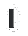
[0024] A figura 8 é uma vista plana superior de uma célula interna não formada exemplar incluindo um elemento absorvente de luz.[0024] Figure 8 is a top plan view of an exemplary unformed internal cell including a light-absorbing element.
[0025] A figura 8A é uma vista plana superior da célula interna não formada da figura 8 com um segundo elemento absorvente de luz.[0025] Figure 8A is a top plan view of the unformed inner cell of Figure 8 with a second light absorbing element.
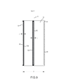
[0026] A figura 9 é uma vista plana superior de uma célula interna não formada exemplar incluindo dois elementos absorventes de luz que são menores na largura do que os elementos absorventes de luz mostrados na figura 7.[0026] Figure 9 is a top plan view of an exemplary unformed internal cell including two light absorbing elements that are smaller in width than the light absorbing elements shown in figure 7.
[0027] A figura 9A é uma vista plana superior da célula interna não formada da figura 9 com um terceiro elemento absorvente de luz.[0027] Figure 9A is a top plan view of the unformed inner cell of Figure 9 with a third light-absorbing element.
[0028] Uma cobertura celular tipicamente inclui uma pluralidade de células alongadas verticalmente alinhadas, que se estendem lateralmente, que podem ser fechadas transversalmente que são aderidas longitudinalmente em células adjacentes superiores e inferiores para formar uma pilha vertical de células. O corte transversal de cada célula pode adotar numerosas formas, tais como hexagonal, octogonal ou suas variações. Embora tais coberturas utilizando células que podem ser fechadas transversalmente sejam orientadas tipicamente, de modo que as células se estendam lateral ou horizontalmente, painéis de tal material podem também ser orientados de modo que as células se estendam verticalmente ou em um ângulo entre o horizontal e vertical.[0028] A cell cover typically includes a plurality of vertically aligned elongated cells, which extend laterally, which can be closed transversely which are adhered longitudinally to adjacent upper and lower cells to form a vertical cell stack. The cross-section of each cell can take on numerous shapes, such as hexagonal, octagonal or their variations. Although such covers using cells that can be closed transversely are typically oriented, so that the cells extend laterally or horizontally, panels of such material can also be oriented so that the cells extend vertically or at an angle between the horizontal and vertical .
[0029] Em algumas modalidades aqui, uma veneziana celular é revelada. Os painéis da cobertura celular são geralmente formados pela montagem de cada célula de uma unidade celular a partir de uma ou mais tiras de material dobrado, curvado ou vincado ao longo de linhas que se estendem longitudinalmente ao longo do comprimento do material. Cada célula formada é então fixada ao longo de uma linha de fixação superior em uma célula posicionada adjacente, mas acima da célula. A célula é também geralmente fixada ao longo de uma linha de fixação inferior em uma célula posicionada adjacente, porém abaixo da célula. Dessa maneira, é formado um painel de células empilhadas.[0029] In some modalities here, a cell shutter is revealed. The cell cover panels are generally formed by assembling each cell of a cell unit from one or more strips of folded, curved or creased material along lines that extend longitudinally along the length of the material. Each formed cell is then attached along an upper attachment line to an adjacent positioned cell, but above the cell. The cell is also generally attached along a lower attachment line to an adjacent, but below the cell. In this way, a panel of stacked cells is formed.
[0030] As unidades celulares são fixadas ao longo das linhas de fixação (superior e inferior) por uma camada fina de adesivo tendo larguras ajustáveis para conectar com segurança as células em células adjacentes acima e abaixo para formar o painel. Tipicamente, ambas as células externa e interna são feitas de um material trançado, não trançado ou de malha. O material não trançado pode incluir fibras naturais ou sintéticas e uma resina para unir as fibras.[0030] Cell units are attached along the attachment lines (top and bottom) by a thin layer of adhesive having adjustable widths to securely connect cells in adjacent cells above and below to form the panel. Typically, both the outer and inner cells are made of a braided, non-braided or mesh material. The non-woven material can include natural or synthetic fibers and a resin to bond the fibers.
[0017] Na conexão das células, a permeabilidade à luz da cobertura pode ser afetada, já que a luz pode ser capaz de atravessar as linhas de conexão entre cada célula adjacente superior e inferior. Isso pode impedir que a cobertura bloqueie completamente a luz (o que pode ser desejado em alguns casos), bem como pode afetar adversamente as qualidades isolantes da cobertura.[0017] When connecting cells, the light permeability of the roof can be affected, since the light may be able to cross the connecting lines between each adjacent upper and lower cell. This can prevent the covering from blocking light completely (which may be desired in some cases), as well as may adversely affect the insulating qualities of the covering.
[0018] Para substancialmente prevenir ou significativamente reduzir a passagem da luz através das linhas de conexão entre cada célula superior e inferior adjacente, um elemento absorvente de luz é posicionado na interface entre as células. O elemento absorvente de luz é formado em uma linha que se estende ao longo do comprimento de uma célula nas regiões de interface entre células adjacentes. O elemento absorvente de luz pode ser contínuo ou segmentado, pode ser linear ou curvado, pode ter larguras variadas e pode ter espessuras variadas. O elemento absorvente de luz pode ser formado como uma parte integral de uma célula ou pode ser um componente separado fixado na célula. Por exemplo, o elemento absorvente de luz pode ser um corante aplicado na superfície de, ou embutido em, uma tira do material que forma a célula. Adicional ou alternativamente, o elemento absorvente de luz pode ser uma peça separada de material, tal como uma camada fina de plástico tendo qualidades absorventes de luz, fixada em uma superfície de uma célula. O elemento absorvente de luz pode ser de várias cores, incluindo cores escuras, dependendo da absorção desejada da luz. Além do mais, o elemento absorvente de luz pode ser posicionado em várias localizações onde a infiltração da luz pode ocorrer entre células adjacentes, tais como entre células adjacentes, entre células internas e externas ou ambos. Dessa maneira, a luz que pode atravessar o lado traseiro ou do caminho de um painel celular na interface de conexão entre as células pode ser absorvida pelo elemento absorvente de luz ao invés de ser transmitida para o lado frontal ou do ambiente do painel celular.[0018] To substantially prevent or significantly reduce the passage of light through the connecting lines between each adjacent upper and lower cell, a light-absorbing element is positioned at the interface between the cells. The light-absorbing element is formed in a line that extends along the length of a cell in the interface regions between adjacent cells. The light-absorbing element may be continuous or segmented, may be linear or curved, may have varying widths and may have varying thicknesses. The light-absorbing element can be formed as an integral part of a cell or it can be a separate component attached to the cell. For example, the light-absorbing element may be a dye applied to the surface of, or embedded in, a strip of the material that forms the cell. Additionally or alternatively, the light-absorbing element may be a separate piece of material, such as a thin layer of plastic having light-absorbing qualities, attached to a cell surface. The light-absorbing element can be of various colors, including dark colors, depending on the desired light absorption. Furthermore, the light-absorbing element can be positioned in various locations where light infiltration can occur between adjacent cells, such as between adjacent cells, between internal and external cells, or both. In this way, light that can pass through the back side or path of a cell panel at the connection interface between cells can be absorbed by the light absorbing element instead of being transmitted to the front or environment side of the cell panel.
[0019] Com referência às figuras 1A e 1B, um painel celular 16 inclui uma pluralidade de unidades celulares 22. Cada unidade celular 22 é conectada operativamente em pelo menos uma unidade celular 22 adjacente. As unidades celulares 22 são fixadas ao longo de linhas de fixação ou regiões de interface. A combinação das unidades celulares 22 forma o painel celular 16. Cada unidade celular 22 pode incluir um volume interior (célula única), dois volumes interiores (célula dupla) definidos por uma célula externa 24 e uma célula interna 26 ou mais volumes interiores em algumas configurações. Se a unidade celular 22 é uma célula dupla, a célula interna 26 pode ser substancialmente recebida dentro da célula externa 24. As duas células 24, 26 podem ser unidas operativamente (por exemplo, via adesivo, costura ou outros prendedores). As duas células 24, 26 formam uma única fileira ou unidade celular 22. Em ou perto da localização de conexão ou interface de cada unidade celular 22, qualquer uma ou ambas a célula externa 24 e a célula interna 26 podem incluir um elemento de absorção de luz. O elemento de absorção de luz pode ser posicionado adjacente ou no ponto de conexão ou interface entre as células 24, 26 e/ou unidades celulares 22.[0019] With reference to figures 1A and 1B, a
[0020] A Fig. 1A é uma vista isométrica de uma cobertura 10 para uma abertura arquitetônica em uma posição estendida. A Fig. 1B é uma vista isométrica da cobertura 10 em uma posição retraída. A cobertura 10 pode incluir um trilho principal 12, um trilho inferior ou final 14 e um painel celular flexível 16 interligando o trilho principal 12 e o trilho inferior 14. A cobertura 10 pode ser movida da posição estendida ilustrada na Fig. 1A para a posição retraída ilustrada na Fig. 1B operando um cordão de controle 18 tendo uma borla 20 localizada em uma extremidade livre do cordão de controle 18. O cordão de controle 18 pode ser conectado em um mecanismo de içamento (tal como cordões de içamento, não mostradas). O mecanismo de içamento pode se estender através do painel 16 desde o trilho principal 12 para o trilho inferior 14 e é operativo para içar o trilho inferior 14 em direção ao trilho principal 12. A cobertura 10 pode incluir uma trava de cordão (não mostrada) dentro do trilho principal 12 para firmar o cordão de controle 18 para manter o painel 16 em uma posição desejada entre totalmente estendido e totalmente retraído. Para estender a cobertura 10, a borla 20 pode subir, proporcionando comprimento extra para o mecanismo de içamento e o trilho inferior 14 (através da gravidade) pode cair. Em outros exemplos, a cobertura 10 pode incluir mecanismos de controle alternados, tais como um sistema automático ou motorizado, sistema de polia e assim por diante.[0020] Fig. 1A is an isometric view of a roof 10 for an architectural opening in an extended position. Fig. 1B is an isometric view of the cover 10 in a retracted position. The cover 10 can include a
[0021] Com referência ainda às figuras 1A e 1B, o painel 16 inclui uma pluralidade de unidades celulares 22 ou fileiras. Cada unidade celular 22 se estende horizontal ou lateralmente através da largura do painel 16 e é verticalmente alinhada com cada outra unidade celular 22. Cada unidade celular 22 é conectada operativamente ao longo do seu comprimento em unidades celulares 22 superiores e inferiores imediatamente adjacentes (descritas em mais detalhes abaixo). Adicionalmente, cada unidade celular 22 pode ser fechada transversalmente, tal que quando a cobertura 10 é retraída, as unidades celulares 22 reduzem na altura e empilham. Por exemplo, a área da seção transversal de cada unidade celular 22 tomada em um ângulo reto com relação ao comprimento do painel 16 fecha em uma maneira desejada para permitir o empilhamento.[0021] With reference also to figures 1A and 1B,
[0022] Com referência às figuras 2B até a 6 (a Fig. 2A é citada abaixo), cada unidade celular 22 pode incluir uma célula externa 24 e uma célula interna 26 pelo menos parcialmente recebida dentro da célula externa 24. A célula externa 24 pode ser formada de uma tira longa, estreita de material tendo bordas longitudinais geralmente paralelas 28. A tira é geralmente curvada ao redor de linhas de curvatura que se estendem ao longo do comprimento da tira para formar uma estrutura geralmente tubular. Quando a célula externa 24 é formada na forma da célula tubular oca, as bordas 28 podem ser posicionadas substancialmente adjacentes, porém separadas uma da outra para definir um vão 29. Nesses exemplos, uma porção da célula interna 26 (por exemplo, a parede superior da célula interna 26) pode ficar exposta através do vão 29.[0022] With reference to figures 2B through 6 (Fig. 2A is cited below), each
[0023] Em outros exemplos, as bordas 28 podem ser posicionadas diretamente adjacentes (incluindo tocando) ou até mesmo se sobrepondo, de modo que não possa existir substancialmente vão entre cada borda 28, ver, por exemplo, a Fig. 5C. Como a célula externa 24 pode ser formada de uma única tira de material, o fundo 36 da célula 24, que pode estar posicionada no lado oposto das bordas 28, pode ser substancialmente contínuo sem vão formado. As bordas 28 da célula externa 24 podem definir uma parede superior 42 da célula 24, de modo que cada célula pode ter uma parede superior 42, uma parede inferior 36 e paredes laterais opostas 30. Cada parede lateral oposta pode definir um vinco externo 34.[0023] In other examples, the
[0024] Ainda com referência às figuras 2B até 6, a célula externa 24 pode incluir paredes laterais superiores 30 movendo-se para baixo e para fora das bordas 28. A superfície interna 33 das paredes laterais 30 pode ficar virada para a célula interna 26 e a superfície externa 35 das paredes laterais 30 pode ficar virada para a abertura arquitetônica ou do ambiente. O vinco externo longitudinal 34 pode ser espaçado de maneira substancialmente igual das bordas 28 e se estender coextensivamente em relação um ao outro. Cada vinco 34 pode ser pelo menos parcialmente pontudo e pode produzir uma curva ou linha de dobra ao longo do comprimento da célula externa 24. Quando o painel celular 16 é retraído e a célula fecha para empilhar, as paredes laterais da célula externa 24 dobram ao longo do vinco 34. Por exemplo, a célula externa 24 pode fechar na linha do vinco 34 quando o trilho inferior 14 retrai o painel celular 16. Abaixo da linha do vinco 34, o material que forma as células externas 24 transita para formar as paredes laterais inferiores 31 que se estendem para baixo e para longe da linha do vinco 34 para formar o fundo 36 da célula externa 24.[0024] Still with reference to figures 2B through 6, the
[0025] Como mostrado nas figuras 2B até 5 e 6, a célula interna 26 pode ter substancialmente a mesma forma de seção transversal e recursos estruturais que a célula externa 24. A célula interna 26, quando o painel celular 16 é estendido, engata a célula externa 24 nas suas paredes superior e inferior 42 e 36, assim formando um vão entre paredes laterais adjacentes. A célula interna 26 pode ser formada de uma tira de material que pode incluir bordas paralelas 46 (ver, por exemplo, figuras 7 a 9). Em algumas implementações, a célula interna 26 pode ser invertida em relação à célula externa 24. Por exemplo, as bordas longitudinais 46 podem ser conectadas operativamente no fundo 36 da célula externa 24 e uma parede superior contínua 50 da célula interna 26 pode ser conectada nas bordas 28 (formando a parede superior 42) da célula externa 24. Adicionalmente, a célula interna 26 pode incluir duas paredes laterais superiores 54 que se estendem para cima e para fora das bordas 46 e duas paredes laterais inferiores 55 que se estendem abaixo dos vincos 60 e transitam para o fundo 57, que inclui as bordas longitudinais 46. Como a célula externa 24, a célula interna 26 fecha ao longo dos vincos 60 da parede lateral quando o painel celular 16 é retraído e as células são empilhadas.[0025] As shown in figures 2B through 5 and 6, the
[0026] As paredes laterais 54, 55 da célula interna 26 podem ser posicionadas, tal que a superfície externa da parede lateral 54, 55 fica virada para a célula externa 24 e a superfície interna 21 fica virada para dentro em direção à parede lateral oposta 54, 55. As paredes laterais superiores 54 transitam para formar as paredes laterais inferiores 55 no vinco 60, e como o vinco 34 na célula externa 24, o vinco 60 pode permitir que a célula interna 26 feche quando o painel celular 16 é retraído. O vinco 60 da célula interna 26 pode ficar aproximadamente alinhado e coextensive com o vinco 34 na célula externa 24, tal que as duas células 24, 26 podem dobrar em alinhamento longitudinal uma com a outra.[0026] The
[0027] Deve ser observado que, em algumas implementações, qualquer uma ou ambas a célula interna 26 e a célula externa 24 podem ser formadas, de modo que possa não existir um vão entre as bordas 28, 46 e, no lugar disso, somente uma costura onde as bordas se tocam ou sobrepõem. Por exemplo, a Fig. 5C é uma vista isométrica da célula interna 26 formada sem um vão entre as bordas 46. A célula externa 24 pode ser formada similarmente, de modo que pode não existir um vão 29 entre as bordas 28. Alternativamente, cada uma das células interna e externa 26, 24 pode ser formada de duas ou mais tiras de material e, assim, podem existir vãos ou costuras formados em ambos o topo e o fundo de cada célula respectiva.[0027] It should be noted that, in some implementations, either or both the
[0028] Similarmente, em alguns exemplos, a forma da seção transversal da célula externa 24 e da célula interna 26 pode ser variada uma da outra. Por exemplo, a célula interna 26 pode ter uma seção transversal circular enquanto que a célula externa 24 pode ter uma seção transversal hexagonal.[0028] Similarly, in some examples, the shape of the cross section of
[0029] Com referência ainda às figuras 2B a 5 e 6, a célula externa 24 e a célula interna 26 podem ter uma forma similar, embora a célula interna 26 possa ser menor do que a célula externa 24. As duas células 24, 26 podem proporcionar isolamento, já que cada célula 24, 26 pode capturar o ar; assim, criando bolsas de ar entre um primeiro lado do painel celular 16 e um segundo lado do painel celular 16. As duas células 24, 26 podem ser substancialmente de qualquer forma, mas podem cada uma geralmente definir um volume. O volume definido por cada célula 24, 26 pode geralmente incluir pelo menos duas aberturas, por exemplo, uma em cada lado da unidade celular 22 em cada lado da cobertura 10. O volume definido, como descrito acima, pode funcionar para capturar o ar de modo a prover o isolamento. Adicionalmente, quando o painel celular 16 é retraído, o volume para cada célula 24, 26 pode diminuir à medida que a unidade celular 22 fecha transversalmente.[0029] With reference also to figures 2B to 5 and 6, the
[0030] Adicionalmente, as duas células 24, 26 podem cooperar para impedir que a luz seja transmitida através do painel celular 16. Por exemplo, qualquer uma ou ambas a célula externa 24 e a célula interna 26 podem incluir materiais de bloqueio ou reflexão do comprimento de onda visível. Em um exemplo, a célula interna 26 pode ser feita de um material de bloqueio de luz (por exemplo, Mylar) e a célula externa 24 pode ser feita de outro material (ou translúcido ou opaco). O material pode ser um material de malha, trançado ou não trançado ou pode ser um tecido e também pode ser feito de material artificial, natural ou uma combinação de materiais. Nesse exemplo, o painel celular 16 pode ter uma aparência estética melhorada, enquanto ainda provendo as funções de bloqueio da luz. Além do mais, as duas células 24, 26 podem também produzir o isolamento de ondas sonoras já que os comprimentos de onda sonoros podem ser reduzidos como de um primeiro lado do painel 16 para um segundo lado do painel 16. Deve ser observado que outros materiais são possíveis para as células 24, 26 e os materiais listados aqui são exemplos somente.[0030] Additionally, the two
[0031] Com referência às figuras 2A a 5 e 6 a 9, a célula externa 24 e a célula interna 26 podem ser unidas operativamente em várias maneiras. A célula interna 26 e a célula externa 24 podem ser unidas através de adesivo 62 posicionado em uma superfície externa da parede superior 50 da célula interna 26. Em algumas implementações, pode existir uma linha de adesivo 62 para cada borda 28 da célula externa 24. Adicionalmente, as duas células 24, 26 podem ser unidas em uma segunda localização. A célula interna 26 pode incluir adesivo 66 posicionado ao longo de uma superfície inferior externa das bordas 46. Como com o adesivo 62, podem existir duas linhas de adesivo 66 para cada borda 46 da célula interna 26.[0031] With reference to figures 2A to 5 and 6 to 9, the
[0032] A primeira unidade celular 22A e a segunda unidade celular 22B podem ser conectadas em uma interface 48, como mostrado nas figuras 2B e 3, tal que uma superfície superior da primeira unidade celular 22A pode ser alinhada e posicionada adjacente a uma superfície inferior da segunda unidade celular 22B. As unidades celulares 22A, 22B podem ser unidas operativamente através de linhas de adesivo 64 posicionadas em uma superfície externa superior de cada célula externa 24. Deve ser observado que a linha de conexão entre as unidades celulares 22A, 22B pode incluir mais do que uma linha de adesivo 64. Juntas as linhas de adesivo 64 podem formar uma região de conexão linear ao longo do comprimento das unidades celulares 22A, 22B.[0032] The
[0033] Com referência à Fig. 2A, em alguns painéis celulares onde cada célula é feita de material ou é de outra forma modelada para pelo menos parcialmente bloquear a passagem da luz através delas, a luz pode escapar através das localizações de conexão 48 entre fileiras de célula, formando uma faixa de luz entre as células quando vista pelo lado frontal ou do ambiente das células. Por exemplo, a luz de um lado traseiro ou do ambiente do painel celular pode ser transmitida ou refletida através do adesivo 64 ou através do material que forma as células (se material sem bloqueio de luz) ou uma combinação de ambos. Listas ou faixas de luz podem ocorrer em várias relações de aspecto do adesivo. Como mostrado na Fig. 2A, a luz pode ser transmitida através das localizações de conexão 48 em várias direções, já que o adesivo 64 (ou outro mecanismo de conexão) pode refratar parcialmente a luz. A dispersão da luz na junção de duas células adjacentes pode ser devido ao material da célula, tal como um tecido, ter um perfil de superfície desigual, a abertura e/ou porosidade do material e/ou quaisquer superfícies refletivas associadas com as células.[0033] With reference to Fig. 2A, in some cell panels where each cell is made of material or is otherwise modeled to at least partially block the passage of light through them, the light may escape through the
[0034] Nesses painéis celulares, mesmo embora a célula externa e/ou a célula interna possa incluir material de reflexão de luz ou não transmissor de luz, a luz pode ser transmitida assim através do painel. O escape da luz através da localização de conexão entre as células passa através ou ao redor do adesivo usado para unir as células adjacentes. Em um exemplo, isso faz com que faixas de luz sejam vistas entre as células quando em uma sala escurecida com uma veneziana celular tendo material de blecaute nas células.[0034] In these cell panels, even though the outer cell and / or the inner cell may include light-reflecting or non-light transmitting material, light can thus be transmitted through the panel. The escape of light through the connection location between cells passes through or around the adhesive used to join adjacent cells. In one example, this causes streaks of light to be seen between cells when in a darkened room with a cell shutter having blackout material in the cells.
[0035] Com referência às figuras 2B a 9, a unidade celular 22 pode incluir um elemento absorvente de luz 70 para bloquear ou absorver a luz, de modo que a luz passando entre as células adjacentes é reduzida ou eliminada. Esse elemento 70, assim, pode reduzir ou eliminar o problema de faixa de luz. Por exemplo, uma lista preta pode ser associada com uma interface 48 e absorver substancialmente toda a luz dispersa no meio de células adjacentes. A unidade celular 22 pode incluir um ou mais elementos absorventes de luz 70 e cada elemento absorvente de luz 70 pode ser posicionado em várias localizações em qualquer uma ou ambas as células 24, 26. Em um exemplo, uma lista ou tira preta impressa é posicionada na célula interna 26. A posição do elemento absorvente de luz 70 pode ser determinada com base nas localizações do adesivo conectando as unidades celulares 22A, 22B, bem como o tipo de material da célula externa 24. Por exemplo, se a célula externa 24 é feita de material que transmite luz, a célula interna 26 pode incluir o elemento absorvente de luz 70, embora o elemento absorvente de luz possa ser parcialmente coberto pela célula externa 24. Isso é porque o elemento absorvente de luz 70 pode absorver qualquer luz que possa atravessar a célula externa 24, bem como a luz que atravessa as localizações de conexão entre as unidades celulares 22A, 22B.[0035] With reference to figures 2B to 9, the
[0036] O elemento absorvente de luz 70 absorve uma quantidade suficiente de luz visível que normalmente atravessaria o vão entre as células adjacentes. O elemento absorvente de luz pode absorver efetivamente por si próprio luz suficiente para minimizar amplamente o efeito de faixa de luz entre células adjacentes ou ele pode trabalhar em conjunto com os outros recursos estruturais na região de conexão (as tiras adesivas, o material da célula) para minimizar ou amplamente eliminar a faixa de luz entre células adjacentes. Assim, a luz que atravessa ou escapa entre as células através da região de conexão para causar a faixa de luz é absorvida ou de outra forma bloqueada pelo elemento absorvente de luz 70 somente ou em combinação com a outra estrutura de célula na proximidade da região de conexão. Em alguns exemplos, o elemento absorvente de luz 70 não é uma parte estrutural da interface 48 entre unidades celulares 22 adjacentes. Em outras palavras, em alguns exemplos, o elemento absorvente de luz 70 não une unidades celulares 22 adjacentes ou transfere cargas através de uma interface 48. Dessa maneira, o elemento absorvente de luz pode ser distinto do mecanismo ou dispositivo de união ou fixação usado para conectar ou acoplar uma unidade celular em uma unidade celular adjacente. Em alguns exemplos, o elemento absorvente de luz 70 é uma parte estrutural da interface 48 entre unidades celulares 22 adjacentes. Em alguns exemplos, o adesivo usado para conectar as células 24, 26 ou unidades celulares 22 pode ser colorido com um corante, tal como um corante preto e funcionar como um elemento absorvente de luz, além de pelo menos parcialmente prender as células ou porções de células. Onde adesivo colorido é utilizado como um elemento absorvente de luz também, o adesivo pode ser posicionado em localizações como mostrado e descrito aqui e/ou pode ser adicionalmente posicionado onde os elementos absorventes de luz separados estão localizados.[0036] The light-absorbing
[0037] Ainda com referência às figuras 2B a 9, o elemento absorvente de luz 70 pode ser um material preto, tal como uma tinta ou corante, ou pode ser um pedaço separado ou pedaços de material laminado firmemente unido no material de célula e posicionado na interface da região de conexão entre as unidades celulares 22A e 22B. Em um exemplo, o elemento absorvente de luz 70 pode ser um corante colorido de preto aplicado na tira de material que forma a célula interna 26 (ver, por exemplo, as figuras 7 a 9). O elemento absorvente de luz 70 pode também ser posicionado na tira do material que forma a célula externa 24 nas localizações apropriadas. Um exemplo de corante ou tinta adequado é uma tinta preta, FAB-PX00, Fabrasflex Black FR vendida por Tokyo Ink, e é aplicado na tira de material em uma camada tendo uma espessura de aproximadamente 0,08 mils, ou aproximadamente 2,1 microns. Um exemplo do elemento absorvente de luz 70 sendo uma peça separada de material laminado é uma camada fina de plástico colorido escuro tendo qualidades absorventes de luz visível e suficientemente unida nas mesmas localizações ou similares que a tinta é aplicada na tira do material de célula e suficientemente segura para proporcionar um apoio adequado para os adesivos usados para unir as células adjacentes. Dessa maneira, a luz que pode atravessar um primeiro lado do painel celular 16 na interface de conexão 48 entre unidades celulares 22 pode ser absorvida pelo elemento absorvente de luz 70 e pode não ser transmitida para o outro lado do painel celular 16.[0037] Still with reference to figures 2B to 9, the
[0038] Em outros exemplos, o elemento absorvente de luz 70 pode ser outras cores escuras, tais como, mas não limitados a, marrom, cinza, azul marinho, azul escuro, marrom escuro ou verde escuro. Além do mais, cada célula 24, 26 pode incluir múltiplos elementos absorventes de luz 70 posicionados em várias localizações onde a infiltração da luz pode ocorrer.[0038] In other examples, the
[0039] Com referência particularmente à Fig. 2B, o painel celular 16 inclui um elemento absorvente de luz 70, que substancialmente previne ou significativamente reduz a infiltração, escape, da luz, ou que de outra forma seja transmitida através das localizações de conexão 48 ou interfaces entre as fileiras de célula 22. Como mostrado na Fig. 2B, a luz que entra no adesivo 64 ou de outra forma entra nas localizações de conexão (por exemplo, através do material de célula externa) é altamente absorvida e substancialmente impedida de atravessar a interface 48 entre as unidades celulares 22A, 22B adjacentes do painel 16. Assim, dependendo do material e das dimensões do painel celular 16, o painel celular 16 pode ser capaz de prevenir substancialmente qualquer transmissão de luz através dele. Isso pode permitir que o painel celular 16 seja usado para criar “salas escuras” e outras áreas onde a luz possa não ser desejada. Adicionalmente, o painel celular 16 pode oferecer propriedades de mais isolamento térmico, já que menos luz pode ser transmitida através do painel 16 para aquecer uma sala. Entretanto, como o painel celular 16 pode ser estendido e retraído, a luz transmitida através de uma abertura arquitetônica particular consegue variar de aproximadamente 0 por cento a aproximadamente 100 por cento.[0039] With particular reference to Fig. 2B, the
[0040] O painel celular 16 na Fig. 2B inclui uma unidade celular inferior 22A e uma unidade celular superior 22B conectadas entre si por um par de linhas de adesivo 64 lateral mente separadas longitudinalmente estendidas. Cada unidade celular 22A, 22B inclui uma célula interna 26 e uma célula externa 24 unidas com linhas de adesivo adicionais 62, 66. Em particular, duas linhas de adesivo 62 lateralmente separadas, estendidas longitudinalmente conectam paredes superiores correspondentes 42, 50 das células externa e interna 24, 26, respectivamente. Similarmente, duas linhas de adesivo 66 lateralmente separadas longitudinalmente estendidas conectam as paredes inferiores correspondentes 36, 57 das células externa e interna 24, 26, respectivamente.[0040]
[0041] Cada célula interna 26 na Fig. 2B tem uma parede superior contínua 50 e uma parede inferior descontínua 57, enquanto que cada célula externa 24 tem uma parede superior descontínua 42 e uma parede inferior contínua 36. Assim, as linhas de adesivo 62 ficam alinhadas com as bordas longitudinais 28 da parede superior descontínua 42, se estendem lateralmente para fora das bordas 28 e são dispostas entre as paredes superiores correspondentes 42, 50. Similarmente, as linhas de adesivo 66 são alinhadas com as bordas longitudinais 46 da parede inferior descontínua 57, se estendem lateralmente para fora das bordas 46 e são dispostas entre as paredes inferiores correspondentes 36, 57.[0041] Each
[0042] As linhas de adesivo 62, 66 podem ser simétricas ao redor de um plano horizontal dividindo a interface 48 entre as unidades celulares inferior e superior 22A, 22B. Além disso, as linhas de adesivo 62, 66 podem ser simétricas ao redor de um plano vertical dividindo a interface 48 entre lados opostos do painel 16. Dentro da região de interface 48, as linhas de adesivo 62, 66 podem ser posicionadas lateralmente para dentro, ou entre, as linhas de adesivos 64. Como mostrado na Fig. 2B, um vão 29 é formado lateralmente entre as bordas longitudinais 28 e as linhas de adesivo 62. Similarmente, um vão 59 é formado lateralmente entre as bordas longitudinais 46 e as linhas de adesivo 66. Os vãos 29, 59 podem se opor dentro da interface 48.[0042] The
[0043] Ainda com referência à Fig. 2B, múltiplos elementos absorventes de luz 70A, 70B são posicionados na interface 48 entre as unidades celulares 22A, 22B adjacentes. Um primeiro elemento absorvente de luz 70A é associado com a unidade celular inferior 22A e geral mente é posicionado em uma porção inferior de um espaço interior 63 da interface 48. Mais especificamente, o primeiro elemento absorvente de luz 70A é posicionado na parede superior 50 da unidade celular inferior 22A no vão 29 e se estende lateralmente através de toda a largura do vão 29. O primeiro elemento absorvente de luz 70A tem aproximadamente a mesma altura que cada linha de adesivo 62 e é rebaixado quando comparado com a parede superior 42 da célula externa 24. Em um exemplo alternativo, como mostrado na Fig. 2C, o primeiro elemento absorvente de luz 70A pode ser embutido e/ou integral com o material de célula e ser coextensive na altura com a parede superior 50 da célula interna 26. Em um exemplo alternativo, como mostrado na Fig. 2C, o segundo elemento absorvente de luz 70B pode ser embutido e/ou integral com o material de célula e ser coextensive na altura com a parede inferior 36 da célula externa 24. Adicionalmente, o elemento absorvente de luz pode ser embutido em somente uma porção da altura (espessura da camada) do material de célula. Com referência novamente à Fig. 2B, a largura do primeiro elemento absorvente de luz 70A é maior do que a sua altura. Em uma implementação, o primeiro elemento absorvente de luz 70A pode ter uma relação de aspectos de pelo menos 5:1. A largura completa das células externa e/ou interna 24, 26 pode ser impressa com, colorida com, ou sobreposta por uma cor escura, tal como preto, que age como um elemento absorvente de luz. A espessura da área impressa ou elemento absorvente de luz 70 pode ser fina e, assim, a relação de aspectos do elemento absorvente de luz 70 pode ser relativamente grande. Por exemplo, em alguns exemplos, uma relação de aspectos do elemento absorvente de luz 70 fica entre aproximadamente 320:1 e aproximadamente 50.000:1.[0043] Still with reference to Fig. 2B, multiple
[0044] Como mostrado na Fig. 2B, o primeiro elemento absorvente de luz 70A é exposto ao espaço interior 63 da interface 48 e fica centralmente localizado na parede superior 50 da célula interna 26, lateralmente equidistante entre as linhas de adesivo 62, 64 e 66. Nessa localização, o primeiro elemento absorvente de luz 70A absorve a luz que é refratada ou direcionada para baixo dos vários recursos associados com a região de interface 48, incluindo as linhas de adesivo 62, 64, 66, as células externas 24 e as células internas 26 (nas configurações onde a célula externa 24 das unidades celulares inferior e/ou superior 22A, 22B é permeável à luz). Na Fig. 2B, a luz foi refratada do adesivo 64 e/ou refletida da parede inferior 36 para o primeiro elemento absorvente de luz 70A, como representado pelas setas dispostas dentro da interface 48. O primeiro elemento absorvente de luz 70A absorve a luz para reduzir ou eliminar substancialmente a transmissão da luz através da interface 48.[0044] As shown in Fig. 2B, the first
[0045] Na Fig. 2B, um segundo elemento absorvente de luz 70B é associado com a unidade celular superior 22B e geralmente fica posicionado em uma porção superior do espaço interior 63 da interface 48. O segundo elemento absorvente de luz 70B é posicionado acima da parede inferior 36 da célula externa 24 da unidade celular superior 22B para absorver qualquer luz que atravesse a célula externa 24 da unidade celular superior 22B (isto é, a célula externa 24 da unidade celular superior 22B é permeável à luz na Fig. 2B). Mais especificamente, o segundo elemento absorvente de luz 70B é conectado na parede inferior 36 e é posicionado no vão 59 e se estende lateralmente através de toda a largura do vão 59. O segundo elemento absorvente de luz 70B tem aproximadamente a mesma altura que cada linha de adesivo 66 e, assim, é rebaixado quando comparado com a parede inferior 57 da célula interna 26. Em um exemplo alternativo, como mostrado na Fig. 2C, o segundo elemento absorvente de luz 70B pode ser embutido no material da célula e ser coextensive na altura com a parede inferior 36 da célula externa 24. Com referência novamente à Fig. 2B, a largura do segundo elemento absorvente de luz 70B é maior do que a sua altura. Em uma implementação, o segundo elemento absorvente de luz 70B pode ter uma relação de aspectos de pelo menos 5:1. A seção transversal vertical da interface 48, se movendo para cima ao longo de um plano vertical dividindo as unidades celulares 22A, 22B inclui a parede superior 50 da célula interna 26 da unidade celular inferior 22A, o primeiro elemento absorvente de luz 70A, um espaço 63, uma parede inferior 36 da célula externa 24 da unidade celular superior 22B e o segundo elemento absorvente de luz 70B.[0045] In Fig. 2B, a second light-absorbing
[0046] Como mostrado na Fig. 2B, o segundo elemento absorvente de luz 70B fica localizado centralmente na parede inferior 36 da célula externa 24, lateralmente equidistante entre as linhas de adesivo 62, 64 e 66. Nessa localização, o segundo elemento absorvente de luz 70B absorve a luz que é refratada ou direcionada para cima a partir dos vários recursos associados com a região de interface 48, incluindo as linhas de adesivo 62, 64, 66, as células externas 24 e as células internas 26 (nas configurações onde a célula externa 24 das unidades celulares inferior e/ou superior 22A, 22B é permeável à luz). Na Fig. 2B, o segundo elemento absorvente de luz 70B é lateralmente alinhado com, mas verticalmente separado de, o primeiro elemento absorvente de luz 70A.[0046] As shown in Fig. 2B, the second light-absorbing
[0047] Em operação, a luz se aproximando da região de interface 48 entre as unidades celulares 22A, 22B adjacentes geralmente encontra as células externas 24 das unidades celulares 22A, 22B, o adesivo 64 ou ambos. Se as células externas 24 são impermeáveis à luz, as células externas 24 refletem os raios de luz, alguns dos quais podem encontrar o adesivo 64. Se as células externas 24 são permeáveis à luz, alguns dos raios de luz atravessam as células externas 24 e podem encontrar inicialmente pelo menos um dos componentes de interface 48, que incluem as linhas de adesivo 62, 64, 66, porções das células externas 24, porções das células internas 26 e o elemento(s) absorvente de luz 70.[0047] In operation, the light approaching the
[0048] Na Fig. 2B, os elementos absorventes de luz 70A, 70B são posicionados interiores às linhas de adesivo 62, 64, 66 e, assim, os raios de luz que chegam precisam atravessar pelo menos uma das linhas de adesivo 62, 64, 66 ou a célula externa 24 antes de alcançarem os elementos absorventes de luz 70A, 70B. Cada linha de adesivo 62, 64, 66 e a célula externa 24, se permeável à luz, geral mente absorvem e/ou refletem uma porção dos raios de luz que chegam. Assim, esses raios de luz absorvidos ou refletidos não são transmitidos através da interface 48 para o outro lado do painel celular 16. Em outras palavras, somente uma porção da luz que se aproxima da interface 48 de um lado do painel é transmitida para o espaço interior 63 da interface 48.[0048] In Fig. 2B, the
[0049] As linhas de adesivo 62, 64, 66 e a célula externa 24 geralmente não incluem superfícies polidas, espelhadas ou especulares, mas preferivelmente têm muitas superfícies desiguais ou pequenas facetas exteriores, algumas das quais podem ser microscópicas. Assim, os raios de luz que atravessam o adesivo 62, 64, 66 ou a célula externa 24 geralmente saem na superfície em um padrão difuso. A maior parte de, se não todos, os raios de luz difundidos encontram e são absorvidos pelos elementos absorventes de luz 70A, 70B, que são seletivamente posicionados no fundo e topo da interface 48, respectivamente. Uma pequena porcentagem dos raios de luz pode passar lateralmente pelos elementos absorventes de luz 70A, 70B. Entretanto, esses raios de luz precisam atravessar pelo menos uma linha adicional de adesivo 62, 64, 66 ou célula externa 24 antes de saírem da interface 48 no outro lado do painel 16. Similar à discussão prévia, as linhas adicionais de adesivo 62, 64, 66 e célula externa 24 absorvem e refletem uma porção desses raios de luz. Assim, qualquer quantidade de luz atravessando as linhas adicionais de adesivo 62, 64, 66 ou célula externa 24 para o outro lado do painel 16 geralmente é minúscula e imperceptível. Em outras palavras, a configuração das linhas de adesivo 62, 64, 66, da célula externa 24, dos elementos absorventes de luz 70A, 70B ou uma combinação desses substancialmente elimina ou significativamente reduz qualquer quantidade de luz atravessando a interface 48. De forma geral, nenhuma quantidade de luz perceptível para o homem é transmitida através da interface 48 a partir de um primeiro lado, que pode ser o lado traseiro ou do caminho, para um segundo lado, que pode ser o lado frontal ou do ambiente, do painel 16, já que a maior parte, se não toda, a luz passando para o espaço interior 63 da interface 48 é absorvida pelo elemento(s) absorvente de luz 70.[0049]
[0050] Como deve ser verificado, embora os elementos absorventes de luz 70A, 70B sejam mostrados como sendo um componente separado fixado em uma unidade celular 22A, 22B, os elementos absorventes de luz 70A, 70B podem ser integrais com a parede de uma unidade celular 22A, 22B. Por exemplo, como previamente descrito, os elementos absorventes de luz 70A, 70B podem ser um corante que é aplicado em uma porção do material de uma unidade celular 22A, 22B associada com a interface 48. Adicionalmente, deve ser verificado, embora dois elementos absorventes de luz 70A, 70B sejam mostrados, que outros números de elementos absorventes de luz podem ser usados. Exemplos incluem somente um elemento absorvente de luz ou mais do que dois elementos absorventes de luz por interface 48.[0050] As should be seen, although light
[0051] Com referência agora à Fig. 3, outra interface 48 exemplar entre painéis celulares 22A, 22B adjacentes é apresentada. De forma geral, nesse exemplo, as linhas de adesivo 62, 64, 66 são posicionadas aproximadamente na mesma localização como no exemplo representado na Fig. 2B. Entretanto, a relação de aspectos das linhas de adesivo 64 lateralmente para fora é alterada. Mais especificamente, a relação de aspectos das linhas de adesivo 64 na Fig. 3 é aproximadamente 3:1, enquanto que a relação de aspectos das linhas de adesivo 64 na Fig. 2B é aproximadamente 1:1. Em alguns exemplos, a relação de aspectos das linhas de adesivo fica entre aproximadamente 1:1 e aproximadamente 10:1. Em alguns exemplos, a relação de aspectos das linhas de adesivo fica entre aproximadamente 1:1 e aproximadamente 5:1 (relação da largura relativa à altura). Em alguns exemplos, a relação de aspectos das linhas de adesivo é aproximadamente 2:1.[0051] Referring now to Fig. 3, another
[0052] Similar ao exemplo representado na Fig. 2B, na Fig. 3, múltiplos elementos absorventes de luz 70A, 70B são posicionados na interface 48 entre unidades celulares 22A, 22B adjacentes. Um primeiro elemento absorvente de luz 70A fica centralmente localizado na parede superior 50 da célula interna 26 da unidade celular inferior 22A e fica posicionado abaixo de duas linhas de adesivo 62, que conectam a parede superior 50 da célula interna 26 na parede superior 42 da célula externa 24. As linhas de adesivo 62 são lateralmente separadas uma da outra por um vão 29, e o elemento absorvente de luz 70A se estende continuamente abaixo de toda a largura de cada linha de adesivo 62 e através do vão 29. Em outras palavras, a largura do primeiro elemento absorvente de luz 70A é o agregado da largura das duas linhas de adesivo 62 e a largura do vão 29.[0052] Similar to the example shown in Fig. 2B, in Fig. 3, multiple
[0053] Ainda com referência à Fig. 3, um segundo elemento absorvente de luz 70B é associado com a unidade celular superior 22B. Em particular, o segundo elemento absorvente de luz 70B é posicionado adjacente a uma borda 46 da parede inferior 57, abaixo da parede inferior 57 e acima de uma linha de adesivo 66, que une as paredes inferiores 57, 36. Em outras palavras, o segundo elemento absorvente de luz 70B é posicionado verticalmente entre a parede inferior 57 da unidade celular superior 22B e uma linha de adesivo 66.[0053] Still with reference to Fig. 3, a second light-absorbing
[0054] O segundo elemento absorvente de luz 70B da Fig. 3 é lateralmente deslocado do centro da parede inferior 36 da célula externa 24 para um lado do painel 16, que pode ser o lado traseiro ou do caminho do painel 16. O segundo elemento absorvente de luz 70B se estende continuamente através de toda a largura da linha de adesivo 66. Em outras palavras, a largura do segundo elemento absorvente de luz 70B é aproximadamente idêntica à largura de uma das linhas de adesivo 66.[0054] The second light-absorbing
[0055] Na configuração representada na Fig. 3, o primeiro elemento absorvente de luz 70A é posicionado abaixo do espaço interior 63 da interface 48 e o segundo elemento absorvente de luz 70B é posicionado acima do espaço interior 63 da interface 48. O primeiro elemento absorvente de luz 70A na Fig. 3 tem uma largura maior do que o elemento absorvente de luz 70A na Fig. 2B e, assim, pode absorver mais luz devido pelo menos em parte a maior área de superfície. O segundo elemento absorvente de luz 70B na Fig. 3 é lateralmente deslocado do centro da interface 48 para um lado do painel 16, de modo a absorver a luz transmitida desse lado do painel 16 antes ou depois de a luz cruzar um ponto intermediário da interface 48. Além disso, o posicionamento do segundo elemento absorvente de luz 70B adjacente a uma borda longitudinal 46 descobre o vão 59 localizado lateralmente entre as bordas opostas 46. Nas configurações onde a célula externa 24 é permeável à luz e a célula interna 26 é impermeável à luz, o vão 59 age como um recurso adicional de prevenção de luz da interface 48, já que a luz que atravessa o vão 59 entra na cavidade interior da célula interna 26, onde a luz é absorvida ou continuamente refletida dentro da cavidade, dessa forma substancialmente impedindo o escape da luz da cavidade interior da célula interna 26.[0055] In the configuration shown in Fig. 3, the first light-absorbing
[0056] Como ainda mostrado nas figuras 4A e 4B, o elemento absorvente de luz 70 pode ser posicionado adjacente à ou abaixo das linhas de adesivo 62, 64, 66. Isso pode ajudar a impedir que a luz seja transmitida através ou ao redor do adesivo 62, 64, 66, desde que a luz pode entrar nas linhas de adesivo 62, 64, 66, mas pode ser absorvida pelo elemento absorvente de luz 70. Nas figuras 4A e 4B, o primeiro elemento absorvente de luz 70A se estende abaixo de linhas de adesivo 62 espacialmente separadas similar à Fig. 3. Entretanto, em contraste com a Fig. 3, o primeiro elemento absorvente de luz 70A mostrado nas figuras 4A e 4B se estende lateralmente para fora de baixo das linhas de adesivo 62 para cada lado do painel para absolver ou coletar a luz antes que a luz encontre as linhas de adesivo 62. O primeiro elemento absorvente de luz 70A nas figuras 4A e 4B cobre uma largura substancial da parede superior 50 da célula interna 26. Por exemplo, o primeiro elemento absorvente de luz 70A cobre mais do que 50% da largura da parede superior 50. Também representado na Fig. 4A, o segundo elemento absorvente de luz 70B pode ser posicionado abaixo da linha de adesivo 66 e se estender lateral mente para fora para a transição da parede inferior 57 para dentro da parede lateral inferior 55 da célula interna 26. Em outras palavras, o segundo elemento absorvente de luz 70B tem uma largura que se estende ao longo de uma parede inferior 57 da célula interna 26 entre uma borda longitudinal 46 e o ponto de transição da parede lateral inferior 55.[0056] As still shown in figures 4A and 4B, the
[0057] Embora as figuras 2B, 3, 4A e 4B mostrem vários exemplos de onde um elemento absorvente de luz 70 pode ficar localizado, muitas outras localizações podem também ser efetivas para substancialmente prevenir a transmissão da luz através de uma interface 48 de unidades celulares 22A, 22B adjacentes. Com referência às figuras 5 a 5C, em algumas implementações, o elemento absorvente de luz 70 pode ser posicionado em localizações adjacentes ou de outra forma próximas da interface ou costura entre as células 24, 26, bem como na interface entre unidades celulares 22.[0057] Although figures 2B, 3, 4A and 4B show several examples of where a
[0058] Em um exemplo e como mostrado nas figuras 5A e 5B, um primeiro elemento absorvente de luz 70A pode ser posicionado em uma superfície superior 51 da parede superior 50 da célula interna 26 e um segundo elemento 70B pode ser posicionado ao longo da borda longitudinal inferior 46 da célula interna 26 (ver Fig. 5B). Assim, a célula interna 26 pode incluir dois elementos absorventes de luz 70A, 70B separados com cada elemento absorvente de luz 70A, 70B posicionado em uma localização de conexão diferente entre a célula externa 24 e a célula interna 26 e/ou a primeira unidade celular 22A e a segunda unidade celular 22B. Como ainda ilustrado na Fig. 5, o primeiro elemento absorvente de luz 70A fica centralmente localizado na parede superior 50 da célula interna 26 e se estende lateralmente para fora através do vão 29, abaixo de ambas as linhas de adesivo 62 espacial mente separadas e lateral mente para fora da borda externa de cada uma das linhas de adesivo 62. O primeiro elemento absorvente de luz 70A tem uma largura que é uma porção substancial de toda a largura da parede superior 50. A largura do primeiro elemento absorvente de luz 70A pode ser pelo menos 50% de toda a largura da parede superior 50. Também ilustrado na Fig. 5, o segundo elemento absorvente de luz 70B é posicionado abaixo da linha de adesivo 66 e se estende da borda longitudinal 46 da parede inferior 57 através de toda a largura da linha de adesivo 66 e lateralmente para fora de uma borda externa da linha de adesivo 66.[0058] In one example and as shown in figures 5A and 5B, a first
[0059] A Fig 5C ilustras com as bordas longitudinais 46 espaçadas diretamente próximas entre si (sem um vão entre elas). A célula interna 26 da Fig. 5C inclui um primeiro elemento absorvente de luz 70A posicionado na parede superior 50 e um segundo elemento absorvente de luz 70B posicionado na parede inferior 57. Como ilustrado, o primeiro elemento absorvente de luz 70A é posicionado centralmente na parede superior 50 aproximadamente equidistante dos lados da célula interna 26. O primeiro elemento absorvente de luz 70A na Fig. 5C tem uma largura que é aproximadamente um terço de toda a largura da parede superior 50. O segundo elemento absorvente de luz 70B é posicionado na parede inferior 57 e é lateral mente deslocado do primeiro elemento absorvente de luz 70A. Embora as figuras 5 a 5C mostrem somente uma única célula, pode existir outra célula, bem como unidades celulares superior e inferior adjacentes que funcionam com os elementos absorventes de luz 70A, 70B para absorver a luz entre as unidades celulares e as células.[0059] Fig 5C illustrated with the
[0060] Como previamente descrito, em algumas implementações, o elemento absorvente de luz 70 pode ser posicionado na célula externa 24. A Fig. 6 é uma vista isométrica da primeira unidade celular 22A e da segunda unidade celular 22B operativamente unidas. O elemento absorvente de luz 70 pode ser conectado operativamente na superfície externa da célula externa 24 perto de uma ou ambas as bordas 28. Alternativa ou adicionalmente, em alguns casos, o elemento absorvente de luz 70 pode ser posicionado na superfície externa da parede inferior 36 da célula externa 24 (como mostrado na unidade celular 22B na Fig. 6B). Assim, o elemento absorvente de luz 70 pode ser posicionado em uma costura ou localização de interface entre as unidades celulares 22. Como ilustrado na Fig. 6, o elemento absorvente de luz 70 se estende lateralmente da borda longitudinal 28 da parede superior 42 da célula externa 24 para a borda interna da linha de adesivo 64. O elemento absorvente de luz 70 pode se estender abaixo da linha de adesivo 64 e lateralmente para fora da borda externa da linha de adesivo 64 em alguns exemplos.[0060] As previously described, in some implementations, the
[0061] O elemento absorvente de luz 70 pode ter larguras variadas que podem depender da configuração particular das células 24, 26 e/ou unidade celular 22, bem como da largura, espessura e colocação do adesivo. Por exemplo, se a interface de conexão entre as unidades celulares 22A, 22B tem uma quantidade maior de adesivo ou costuras adicionais, um elemento absorvente de luz 70 mais largo pode ser necessário a fim de absorver quantidades apropriadas de luz. Adicionalmente, em alguns exemplos, pode ser desejável que o elemento absorvente de luz 70 tenha uma largura menor, de modo que ele não possa ficar visível de um ângulo de visualização normal por um usuário. Isso pode ser especialmente desejável nos casos onde a célula externa 24 pode ser formada de um material colorido mais claro, tal que a cor do elemento absorvente de luz 70 possa ficar visível através da célula externa 24. O elemento absorvente de luz 70 pode se estender somente abaixo do adesivo ou pode se estender lateralmente de debaixo de qualquer um ou ambos os lados do adesivo.[0061] The light-absorbing
[0062] Em algumas implementações, o elemento absorvente de luz 70 pode ser incorporado em ou no material usado para criar a célula interna 26 e/ou a célula externa 24. Por exemplo, as figuras 7 a 10 ilustram vistas planas de uma célula interna não formada 26 incluindo o elemento absorvente de luz 70. Como descrito acima, a célula interna 26 pode ser um material de bloqueio de luz ou de redução de luz, tais como Mylar, poliuretano e poliolefinas, e os elementos absorventes de luz 70A, 70B podem ser porções enegrecidas ou tingidas do material da célula interna 26. absorventes de luz 70A e 70B separados posicionados na célula interna não formada 26. Como observado acima, as células 24, 26 são feitas de tiras longas e estreitas de material dobrado, curvado ou vincado ao longo de linhas longitudinais. A tira de material 76 pode ter uma largura total F e os elementos absorventes de luz 70A, 70B podem ter larguras G, H que são menores do que a largura F do material 76. Como brevemente descrito acima, a tira de material 76 pode ter uma primeira cor e o elemento absorvente de luz 70 pode ser uma porção tingida de preto do material 76.[0062] In some implementations, the
[0063] A Fig. 7 e um primeiro examplo ilustrando dois elementos absorvente de luz 70A e 70B[0063] Fig. 7 and a first example illustrating two light
[0064] O primeiro elemento absorvente de luz 70A pode ser posicionado perto de uma linha média ou central 77 da tira de material 76, tal que quando a célula interna 26 é formada, o primeiro elemento absorvente de luz 70A pode ser posicionado na superfície externa da parede superior contínua 50 da célula interna 26 (ver Fig. 5). O primeiro elemento absorvente de luz 70A pode ser ligeiramente fora de centro da linha central 77 do material 76. Por exemplo, como mostrado na Fig. 7, o primeiro elemento absorvente de luz 70A pode terminar em uma linha central 77 da largura F do material 76. As linhas de adesivo 62 para conectar cooperativamente a célula interna 26 na célula externa 24 podem ser posicionadas em cima do elemento absorvente de luz 70, tal que o elemento absorvente de luz 70 pode se estender além de qualquer lado das linhas de adesivo 62. Em outros exemplos, as linhas de adesivo 62 podem ser posicionadas fora do centro e adjacentes ao elemento absorvente de luz 70.[0064] The first
[0065] O segundo elemento absorvente de luz 70B pode ser posicionado adjacente a uma das bordas longitudinais 46 da célula interna 26. Por exemplo, com referência às figuras 5, 7 e 8A, o segundo elemento absorvente de luz 70B pode ser posicionado na superfície inferior 53 da célula interna 26 em ou adjacente à borda longitudinal 46. Como com o primeiro elemento absorvente de luz 70A, as linhas de adesivo 66 podem ser posicionadas em cima de ou adjacentes ao segundo elemento absorvente de luz 70B. O segundo elemento absorvente de luz 70B pode ser especialmente útil para absorver a luz que pode entrar através do material da célula externa 24. Como descrito acima, em algumas implementações, a célula externa 24 pode ser um material transmissor de luz. Nessa implementação, o segundo elemento absorvente de luz 70B pode ser pelo menos parcialmente coberto da interface 48 entre unidades celulares 22A, 22B (ver figuras 3 e 5) e ainda funcionar para absorver a luz que poderia ser transmitida potencialmente de outra forma de um lado do painel 16 para o outro. Isso é porque a luz poderia entrar através da célula externa 24 e sem o elemento absorvente de luz 70B conseguiria ser transmitida através do topo 30 da célula externa 24 e através da interface 48. Mas, com o segundo elemento absorvente de luz 70B, a luz é absorvida antes de ser transmitida através da interface 48.[0065] The second light-absorbing
[0081] Um terceiro elemento absorvente de luz 70C pode ser posicionado adjacente a outra das bordas longitudinais 46 da célula interna 26. Por exemplo, com referência a ambas as figuras 7A e 9A, o terceiro elemento absorvente de luz 70C pode ser posicionado na superfície inferior 53 da célula interna 26 em ou adjacente à borda longitudinal 46. Como com o primeiro e o segundo elementos absorventes de luz 70A, 70B, as linhas de adesivo 66 podem ser posicionadas em cima de ou adjacentes ao terceiro elemento absorvente de luz 70C.[0081] A third light-absorbing
[0082] As larguras do primeiro elemento absorvente de luz 70A, do segundo elemento absorvente de luz 70B e do terceiro elemento absorvente de luz 70C podem ser variadas. Por exemplo, as figuras 7 e 7A ilustram o primeiro elemento absorvente de luz 70A como tendo uma largura G, o segundo elemento absorvente de luz como tendo uma largura H e o terceiro elemento absorvente de luz como tendo uma largura J. Nesse exemplo, dependendo da largura F do material, a largura G do primeiro elemento absorvente de luz pode ser aproximadamente 1,27 cm (% polegada), a largura H do segundo elemento absorvente de luz 70B pode ser aproximadamente 0,71 cm (9/32 de uma polegada) e a largura J do terceiro elemento absorvente de luz 70C pode ser aproximadamente 0,71 cm (9/32 de uma polegada) e a largura J do terceiro elemento absorvente de luz 70C pode ser aproximadamente 0,40 cm (5/32 de uma polegada). Embora dimensões diferentes sejam possíveis, em alguns casos, a largura do primeiro elemento absorvente de luz 70A pode ser aproximadamente 1/6 da largura F do material 76. Nesse exemplo, as larguras G, H, J dos elementos absorventes de luz 70A, 70B, 70C podem ser mais finas, de modo que o usuário não consiga ver substancialmente os elementos absorventes de luz 70A, 70B por ângulos de visualização normais.[0082] The widths of the first light-absorbing
[0083] As figuras 8 e 8A são outro exemplo de uma tira do material 76 usado para formar a célula interna 26 ou a célula externa 24. Como mostrado no exemplo da figura 8, pode existir um único elemento absorvente de luz 70 com uma largura K que pode ser aproximadamente metade da largura F do material 76. Dessa maneira, metade da superfície externa da célula interna 26 pode incluir o elemento absorvente de luz 70A. Similarmente, embora não mostrado na figura 8, em alguns casos, o elemento absorvente de luz 70 pode ser posicionado em toda a superfície externa da célula interna 26. Em outras palavras, toda a superfície externa da célula interna 26 pode ser tingida de preto. Como mostrado na figura 8A, um segundo elemento absorvente de luz 70B com uma largura J pode ser posicionado adjacente a uma borda longitudinal 46. Nesse exemplo, mais da metade da superfície externa da célula interna 26 é associada ∞m um elemento absorvente de luz 70.[0083] Figures 8 and 8A are another example of a strip of
[0066] A figura 9 é outro exemplo dos elementos absorventes de luz 70A, 70B. Nesse exemplo, as larguras dos elementos absorventes de luz 70A, 70B podem ser substancialmente reduzidas. Isso pode permitir que o material da célula externa 24 seja de uma cor mais clara desde que a cor dos elementos absorventes de luz 70A, 70B pode ser escura, as larguras maiores podem ser visíveis através da célula externa 24. Com uma largura mais estreita, é menos provável que os elementos 70A e 70B sejam vistos através de um material mais claro. Em um exemplo, a largura F do material pode ser aproximadamente 7,62 cm (3 polegadas). O primeiro elemento absorvente de luz 70A pode ter uma largura L que pode ser aproximadamente 0,48 cm (3/16 de uma polegada) e o segundo elemento absorvente de luz 70B pode ter uma largura J que pode ser aproximadamente 0,40 cm (5/32 de uma polegada). Entretanto, outras dimensões são também aplicáveis, dependendo da largura do material 76 e/ou das larguras desejadas dos elementos absorventes de luz 70A, 70B. Nesse exemplo, os elementos absorventes de luz 70A, 70B podem ser de largura substancialmente reduzida, mas podem ainda ser capazes de impedir substancialmente a transmissão da luz de um lado do painel celular 16 para um segundo lado do painel celular 16. A Fig. 9A inclui um terceiro elemento absorvente de luz 70C tendo a mesma largura J que o segundo elemento absorvente de luz 70B. Como representado, o segundo e o terceiro elementos absorventes de luz 70B, 70C são simétricos ao redor da linha central 77. Embora não representado na Fig. 9A, o primeiro elemento absorvente de luz 70A pode ser centralizado ao longo da linha central 77, de modo que a linha central delineia a tira do material 76 em duas metades ou partes longitudinais iguais.[0066] Figure 9 is another example of the
[0067] A descrição precedente tem aplicação ampla. Por exemplo, embora os exemplos revelados aqui possam focalizar na posição ou largura do elemento absorvente de luz, deve ser verificado que os conceitos revelados aqui podem ser aplicados igualmente a geralmente qualquer posição ou largura do elemento absorvente de luz. Similarmente, embora o elemento absorvente de luz tenha sido discutido com relação a ser um elemento separado, os dispositivos e as técnicas são igualmente aplicáveis em modalidades onde a célula interna ou a célula externa é formada integralmente com o elemento absorvente de luz. Por exemplo, o material absorvente de luz pode ser embutido na tira de material que forma a célula (na localização posicionai desejada) ou pode ser abrangido por toda a espessura (na localização posicionai certa) da tira do material que forma a célula. Adicionalmente, o elemento absorvente de luz pode ser formado de um pedaço separado de material laminado, tal como um tecido trançado ou não trançado feito de material natural ou artificial. O elemento absorvente de luz desse tipo pode ser posicionado e/ou firmado em localizações desejadas por costura, adesivo, prendedores ou outros tipos de fixação. Dessa forma, a discussão de qualquer modalidade é planejada somente para ser explicativa e não é planejada para sugerir que o escopo da revelação, incluindo as reivindicações, é limitado a esses exemplos. Também, embora os materiais usados para formar as células nos exemplos descritos aqui sejam geralmente material flexível, é considerado que eles possam ser rígidos ou semirrígidos ou uma combinação e feitos de material artificial ou natural ou uma combinação de materiais. Todas as referências de direção (por exemplo, proximal, distal, superior, inferior, para cima, para baixo, esquerda, direita, lateral, longitudinal, frontal, traseira, topo, fundo, acima, abaixo, vertical, horizontal, radial, axial, horário e anti-horário) são somente usadas com finalidades de identificação para ajudar no entendimento do leitor da presente revelação e não para criar limitações, particularmente quanto à posição, orientação ou uso dessa revelação. Referências de conexão (por exemplo, fixado, acoplado, conectado e unido) devem ser interpretadas amplamente e podem incluir membros intermediários entre uma coleção de elementos e movimento relativo entre os elementos a menos que indicado de outra forma. Como tal, as referências de conexão não sugerem necessariamente que dois elementos estão diretamente conectados e em relação fixa entre si. Os desenhos são com finalidades de ilustração somente e as dimensões, posições, ordem e tamanhos relativos refletidos nos desenhos anexos a eles podem variar.[0067] The preceding description has wide application. For example, while the examples disclosed here may focus on the position or width of the light absorbing element, it should be noted that the concepts disclosed here can be applied equally to generally any position or width of the light absorbing element. Similarly, although the light-absorbing element has been discussed with respect to being a separate element, the devices and techniques are equally applicable in modalities where the inner cell or the outer cell is integrally formed with the light-absorbing element. For example, the light-absorbing material can be embedded in the cell-forming material strip (at the desired positional location) or can be covered by the entire thickness (at the right positional location) of the cell-forming material strip. In addition, the light-absorbing element may be formed of a separate piece of laminated material, such as a woven or nonwoven fabric made of natural or artificial material. The light-absorbing element of this type can be positioned and / or secured in desired locations by sewing, adhesive, fasteners or other types of fixation. Accordingly, the discussion of any modality is intended only to be explanatory and is not intended to suggest that the scope of the disclosure, including the claims, is limited to these examples. Also, although the materials used to form the cells in the examples described here are generally flexible material, it is considered that they can be rigid or semi-rigid or a combination and made of artificial or natural material or a combination of materials. All direction references (for example, proximal, distal, upper, lower, up, down, left, right, lateral, longitudinal, front, rear, top, bottom, above, below, vertical, horizontal, radial, axial , clockwise and counterclockwise) are only used for identification purposes to assist the reader's understanding of the present disclosure and not to create limitations, particularly as to the position, orientation or use of that disclosure. Connection references (for example, fixed, coupled, connected and joined) should be interpreted widely and may include intermediate members between a collection of elements and relative movement between the elements unless otherwise indicated. As such, the connection references do not necessarily suggest that two elements are directly connected and in fixed relation to each other. The drawings are for illustration purposes only and the relative dimensions, positions, order and sizes reflected in the drawings attached to them may vary.
Claims (14)
Applications Claiming Priority (3)
| Application Number | Priority Date | Filing Date | Title |
|---|---|---|---|
| US201161528028P | 2011-08-26 | 2011-08-26 | |
| US61/528,028 | 2011-08-26 | ||
| PCT/US2012/052473 WO2013032997A1 (en) | 2011-08-26 | 2012-08-27 | Feature for inhibiting light stripe between cellular elements in a covering for an architectural opening |
Publications (2)
| Publication Number | Publication Date |
|---|---|
| BR112014004045A2 BR112014004045A2 (en) | 2017-03-07 |
| BR112014004045B1 true BR112014004045B1 (en) | 2020-11-17 |
Family
ID=47756782
Family Applications (1)
| Application Number | Title | Priority Date | Filing Date |
|---|---|---|---|
| BR112014004045-1A BR112014004045B1 (en) | 2011-08-26 | 2012-08-27 | cover for an architectural opening |
Country Status (16)
| Country | Link |
|---|---|
| US (2) | US9885812B2 (en) |
| EP (1) | EP2748399B1 (en) |
| JP (2) | JP6140165B2 (en) |
| KR (1) | KR102022442B1 (en) |
| CN (1) | CN104040105B (en) |
| AU (1) | AU2012300268B2 (en) |
| BR (1) | BR112014004045B1 (en) |
| CA (1) | CA2844515C (en) |
| CL (1) | CL2014000423A1 (en) |
| CO (1) | CO6920275A2 (en) |
| DK (1) | DK2748399T3 (en) |
| HK (1) | HK1201897A1 (en) |
| MX (1) | MX359417B (en) |
| PL (1) | PL2748399T3 (en) |
| TW (2) | TWI563949B (en) |
| WO (1) | WO2013032997A1 (en) |
Families Citing this family (20)
| Publication number | Priority date | Publication date | Assignee | Title |
|---|---|---|---|---|
| CN102061878B (en) | 2003-12-22 | 2016-03-30 | 亨特道格拉斯有限公司 | As the retractible shading piece of building apertured cover |
| US9366080B2 (en) | 2008-11-18 | 2016-06-14 | Hunter Douglas Inc. | Slatted roller blind |
| KR101926779B1 (en) | 2010-04-16 | 2018-12-07 | 헌터더글라스인코포레이티드 | A process and system for manufacturing a roller blind |
| MX361607B (en) * | 2010-06-23 | 2018-12-05 | Hunter Douglas Inc Star | Plastic double-cell covering for architectural openings. |
| SG194164A1 (en) | 2011-04-15 | 2013-11-29 | Hunter Douglas | Covering for architectural opening including cell structures biased to open |
| CA2844518C (en) | 2011-08-26 | 2019-10-29 | Hunter Douglas Inc. | Double pleat cellular shade element |
| US9885812B2 (en) | 2011-08-26 | 2018-02-06 | Hunter Douglas Inc. | Feature for inhibiting light stripe between cellular elements in a covering for an architectural opening |
| USD734061S1 (en) * | 2013-04-01 | 2015-07-14 | Hunter Douglas Inc. | Portion of a cellular shade component |
| USD734060S1 (en) | 2013-04-01 | 2015-07-14 | Hunter Douglas Inc. | Cellular shade component |
| WO2015175451A1 (en) * | 2014-05-12 | 2015-11-19 | Hunter Douglas, Inc. | Cell-in-cell configurations for a cellular shade assembly |
| USD764836S1 (en) | 2014-09-08 | 2016-08-30 | Hunter Douglas Inc. | Covering for an architectural opening having multiple columns of double cells |
| USD789116S1 (en) * | 2014-12-09 | 2017-06-13 | Hunter Douglas Inc. | Sample deck for selecting a covering for an architectural opening |
| US10604998B2 (en) | 2015-02-13 | 2020-03-31 | Hunter Douglas Inc. | Shading display and sample |
| CA2956655A1 (en) | 2016-06-30 | 2017-12-30 | Hunter Douglas Inc. | Architectural covering and method of manufacturing |
| US10597935B2 (en) | 2017-01-25 | 2020-03-24 | Hunter Douglas Inc. | Vertical cellular drape for an architectural structure |
| CN107023127A (en) * | 2017-05-23 | 2017-08-08 | 清华大学 | A kind of fixed sunshade expanded metals |
| US11459821B2 (en) | 2019-02-05 | 2022-10-04 | Hunter Douglas Inc. | Headrail for an architectural-structure covering |
| EP4013268A4 (en) * | 2019-08-13 | 2023-09-06 | Molo Design, Ltd. | Flexible furniture with wood panels and related methods |
| USD951662S1 (en) * | 2019-10-03 | 2022-05-17 | Molo Design, Ltd. | Adjustable partition |
| USD944020S1 (en) * | 2019-10-03 | 2022-02-22 | Molo Design, Ltd. | Adjustable partition |
Family Cites Families (184)
| Publication number | Priority date | Publication date | Assignee | Title |
|---|---|---|---|---|
| USRE22311E (en) | 1943-05-11 | Louver bund | ||
| US2118134A (en) | 1937-11-17 | 1938-05-24 | Allison Charles Fred | Collapsible blind or shade |
| US2201356A (en) | 1938-11-21 | 1940-05-21 | Gertrude H Terrell | Window fixture |
| US2264140A (en) * | 1939-02-01 | 1941-11-25 | Rudolph Axel | Transparent sunshade |
| US2318525A (en) | 1942-05-26 | 1943-05-04 | American Pulley Co | Blind |
| US2625689A (en) * | 1950-12-28 | 1953-01-20 | Bourne Mills | Drapery |
| US3370972A (en) | 1964-09-11 | 1968-02-27 | Du Pont | Coated biaxially oriented polypropylene film |
| US3386490A (en) | 1967-01-30 | 1968-06-04 | Kandel Walter | Fringed venetian blind |
| US3487875A (en) | 1968-01-23 | 1970-01-06 | Tudoran Tradeshop Inc | Self-operating drapery |
| US3490515A (en) | 1968-05-06 | 1970-01-20 | Walter Kandel | Venetian blind with detachably mounted fringe elements |
| USRE29340E (en) | 1970-12-29 | 1977-08-02 | Toyo Boseki Kabushiki Kaisha | Composite film |
| DK133073C (en) | 1974-04-29 | 1976-08-30 | M O H Rasmussen | HEAT INSULATING CURTAIN |
| JPS5231078U (en) | 1975-08-26 | 1977-03-04 | ||
| US4069857A (en) | 1976-04-12 | 1978-01-24 | Clopay Corporation | Roman shade and method for making same |
| DE2843405A1 (en) | 1978-10-05 | 1980-04-24 | Franz Halouska | Venetian blind swivelling slats - have light absorbing as well as light reflecting side |
| AU542729B2 (en) * | 1979-06-08 | 1985-03-07 | Koster Patente G.m.b.H. | Plant for the automatic control of the incident solar flux |
| US5037700A (en) | 1981-01-19 | 1991-08-06 | National Starch And Chemical Investment Holding Corporation | Flexible laminates |
| US4397346A (en) | 1981-06-01 | 1983-08-09 | Warm Window, Inc. | Insulated window shade |
| USD277061S (en) | 1982-06-24 | 1985-01-08 | Picoy Anthony R | Roman shade |
| US4542602A (en) | 1982-07-01 | 1985-09-24 | Hoverson William D | Method and apparatus for making a Roman shade |
| US4647488B1 (en) | 1984-08-07 | 1994-12-27 | Hunter Douglas | Method and apparatus for mounting and sealing honeycomb insulation |
| US4625786A (en) * | 1984-12-05 | 1986-12-02 | Neil A. Carter | Insulated window shade assembly |
| JPS61234552A (en) | 1985-04-10 | 1986-10-18 | Nippon Gakki Seizo Kk | Conducting plate material |
| US4739816A (en) | 1985-08-30 | 1988-04-26 | Levolor Lorentzen, Inc. | Venetian blind system for greenhouses |
| US4915153A (en) | 1985-10-17 | 1990-04-10 | Toti Andrew J | Vertical window covering systems |
| US4677013A (en) | 1985-10-25 | 1987-06-30 | Hunter Douglas Inc. | Honeycomb structure having a longitudinally extending back face |
| US4676855A (en) | 1985-10-25 | 1987-06-30 | Hunter Douglas, Inc. | Method of fabricating honeycomb structures |
| US4677012A (en) | 1985-11-07 | 1987-06-30 | Hunter Douglas Inc. | Honeycomb structure with band joined folded material and method of making same |
| GB8609550D0 (en) | 1986-04-18 | 1986-05-21 | Mobil Plastics Europ Inc | Polypropylene films |
| US4698276A (en) | 1986-05-23 | 1987-10-06 | Guilford Mills, Inc. | Differential density fabric |
| US4751115A (en) * | 1986-11-06 | 1988-06-14 | Smith James P | Reflective sun screen |
| US4999073A (en) | 1987-03-11 | 1991-03-12 | Jamee Kao | Honeycomb pleater |
| US5620035A (en) | 1987-03-25 | 1997-04-15 | Judkins; Ren | Material utilizing flexible strands |
| WO1988007345A1 (en) | 1987-03-25 | 1988-10-06 | Verosol Usa, Inc. | Shade and method for the manufacture thereof |
| US4974656A (en) | 1987-03-25 | 1990-12-04 | Verosol Usa Inc. | Shade and method for the manufacture thereof |
| US5205333A (en) | 1987-03-25 | 1993-04-27 | Verosol Usa Inc. | Shade and method for the manufacture thereof |
| US4943454A (en) | 1987-08-28 | 1990-07-24 | Hunter Douglas, Inc. | Expandable collapsible product and method and apparatus for its manufacture |
| US4884612A (en) | 1988-06-20 | 1989-12-05 | Comfortex Corporation | Pleated blind with articulative slat extensions |
| US4884618A (en) | 1988-08-05 | 1989-12-05 | Christopher Steeves | Roller blind mounting and rolling system |
| US4846243A (en) | 1988-08-19 | 1989-07-11 | Graber Industries, Inc. | Foldable window covering |
| US4921032A (en) | 1988-12-02 | 1990-05-01 | Appropriate Technology Corporation | Roman shades |
| US5193601A (en) | 1988-12-22 | 1993-03-16 | Comfortex Corporation | Multi-cellular collapsible shade |
| US5043039A (en) | 1989-01-25 | 1991-08-27 | Hunter Douglas Inc. | Method of manufacture of expandable and collapsible cellular shades of sheer fabric |
| US5702552A (en) * | 1989-10-05 | 1997-12-30 | Springs Window Fashions Division, Inc. | Method for making a pleated expandable cellular product for window coverings |
| US5160563A (en) | 1989-10-05 | 1992-11-03 | Graber Industries, Inc. | Method and apparatus for making an expandable cellular shade |
| US4984617A (en) | 1989-11-02 | 1991-01-15 | Comfortex Corporation | Enveloped blind assembly using independently actuated slats within a cellular structure |
| US5097884A (en) | 1989-11-06 | 1992-03-24 | Hunter Douglas Inc. | Roman shade |
| US5090098A (en) | 1989-11-06 | 1992-02-25 | Hunter Douglas Inc. | Method of manufacturing a roman shade |
| NL9000804A (en) | 1990-04-05 | 1991-11-01 | Schoen Bv | PULL-UP CURTAIN, PROFILE THEREFOR AND METHOD FOR FOLDING A TRACK OF MATERIAL WITH THE PROFILE. |
| US5104469A (en) | 1990-05-09 | 1992-04-14 | Hunter Douglas Inc. | Method of making a roman shade |
| US5129440A (en) | 1990-05-09 | 1992-07-14 | Hunter Douglas Inc. | Roman shade |
| US5603368A (en) | 1990-05-09 | 1997-02-18 | Hunter Douglas Inc. | Roll up roman shade |
| NZ248872A (en) | 1990-09-06 | 1994-10-26 | Hunter Douglas International | Forming honeycomb type window shades: side by side strips adhered between two webs |
| US5158632A (en) | 1990-10-15 | 1992-10-27 | Hunter Douglas Inc. | Method of making an expandable and collapsible window covering |
| US5482750A (en) * | 1991-01-02 | 1996-01-09 | Hunter Douglas Inc. | Multiple cell honeycomb insulating panel and method of hanging |
| JPH0519306A (en) * | 1991-07-16 | 1993-01-29 | Nippon Sheet Glass Co Ltd | Fully solid-state dimming device and dimming method with the same |
| US5205334A (en) | 1991-10-03 | 1993-04-27 | Verosol Usa Inc. | Double layer shade |
| US6066382A (en) | 1991-11-13 | 2000-05-23 | Hunter Douglas Inc. | Treated fabric and expandable and retractable fabric structures made therefrom |
| US5207257A (en) | 1992-09-25 | 1993-05-04 | Springs Window Fashions Division, Inc. | Adjustable expandable and collapsible shade |
| US6068039A (en) | 1992-09-28 | 2000-05-30 | Judkins; Ren | Material for venetian type blinds |
| US5490533A (en) | 1993-04-05 | 1996-02-13 | Carter Mark C | Collapsible shelter with elevated canopy |
| US5547006A (en) | 1993-05-04 | 1996-08-20 | Hunter Douglas Inc. | Roll-up cellular shades |
| US5390720A (en) | 1993-07-09 | 1995-02-21 | Hunter Douglas, Inc. | Tubular cell window covering with undulations along the length of the cells |
| US5409050A (en) | 1993-09-24 | 1995-04-25 | Hong; Amy | Venetian blind |
| US5455098A (en) | 1994-01-07 | 1995-10-03 | Cheng; Tai-Ping | Decorative pleats and method of manufacture |
| US5485875A (en) | 1994-03-31 | 1996-01-23 | Springs Window Fashions Division, Inc. | Window shade with break-away attachment of lift cords to bottom rail |
| EP0688935A1 (en) | 1994-06-21 | 1995-12-27 | Newell Operating Company | Blind with curtain |
| US5560976A (en) | 1994-11-29 | 1996-10-01 | Teh Yor Industrial Co., Ltd. | Dual cell honeycomb structure |
| US5566735A (en) | 1995-03-28 | 1996-10-22 | Verosol Usa Inc. | Roman-type shade |
| US5630898A (en) | 1995-03-29 | 1997-05-20 | Judkins; Ren | Pleated and cellular materials and method for the manufacture thereof using a splitter |
| USD439785S1 (en) | 1995-05-10 | 2001-04-03 | Hunter Douglas Inc. | Curved tail vane for use in coverings for architectural openings |
| US5632316A (en) | 1995-08-07 | 1997-05-27 | Cohen; Leone A. | Venetian blind with individually adjustable slats |
| US5837084A (en) | 1995-09-14 | 1998-11-17 | Comfortex Corporation | Method of making a single-cell honeycomb fabric structure |
| US5787951A (en) | 1995-12-15 | 1998-08-04 | Kabushiki Kaisha Nichibei | Roman shade |
| JP2000505517A (en) | 1996-03-01 | 2000-05-09 | パスケヴイシウス,ステフアン,ジグマス | Blind improvements |
| US5649583A (en) | 1996-04-29 | 1997-07-22 | Ching Feng Blinds Ind. Co., Ltd. | Waterfall-like window curtain structure |
| US5706876A (en) | 1996-07-29 | 1998-01-13 | Lysyj; Phillip A. | Cordless, roller bar cellular shade |
| US5813447A (en) | 1996-07-29 | 1998-09-29 | Lysyj; Phillip A. | Cordless cellular and pleated shade |
| AUPO343896A0 (en) | 1996-11-06 | 1996-12-05 | Brownlie, Michael Andrew | Roman shade fold forming batten |
| US5791390A (en) | 1997-02-06 | 1998-08-11 | Rollease, Inc. | Single control system for operating top-down-bottom-up shades |
| US6024819A (en) * | 1997-10-09 | 2000-02-15 | Comfortex Corporation | Fabric venetian blind and method of fabrication |
| US5999316A (en) * | 1997-12-06 | 1999-12-07 | 3M Innovative Properties Company | Light valve with rotating polarizing element |
| US6302181B1 (en) | 1998-01-07 | 2001-10-16 | Springs Window Fashions Lp | Window covering with artificial creases and method of manufacturing same |
| US5974763A (en) | 1998-01-23 | 1999-11-02 | Hunter Douglas Inc. | Cell-inside-a-cell honeycomb material |
| US6103336A (en) * | 1998-01-28 | 2000-08-15 | Hunter Douglas Inc. | Laminate honeycomb material |
| US6006812A (en) | 1998-03-17 | 1999-12-28 | Comfortex Corporation | Sheer support window covering |
| US6223804B1 (en) | 1998-05-13 | 2001-05-01 | Andrew J. Toti | Hinge mechanism and window cover system |
| JP2000185360A (en) | 1998-12-24 | 2000-07-04 | Kanegafuchi Chem Ind Co Ltd | Functional material laminate and its manufacture |
| US6416842B1 (en) * | 1999-01-22 | 2002-07-09 | Hunter Douglas Inc. | Dual-laminate honeycomb material |
| DE29910899U1 (en) | 1999-06-22 | 1999-09-23 | Sks Stakusit Bautechnik Gmbh | Roller shutters |
| JP3589100B2 (en) * | 1999-07-22 | 2004-11-17 | 富士電機ホールディングス株式会社 | Fluorescence conversion filter and organic light emitting device having fluorescence conversion filter |
| USD436783S1 (en) | 1999-09-24 | 2001-01-30 | James S Cooper | Interchangable vertical blind |
| CA2344617C (en) | 2000-04-19 | 2009-08-04 | Hunter Douglas Inc. | Enclosed retractable panel made from cell-inside-a-cell honeycomb material |
| US7377084B2 (en) | 2000-04-24 | 2008-05-27 | Hunter Douglas Inc. | Compressible structural panel |
| US6497266B1 (en) * | 2000-06-14 | 2002-12-24 | Newell Window Furnishings | Window covering slat |
| US6354353B1 (en) | 2000-06-14 | 2002-03-12 | Newell Window Furnishings, Inc. | Door and window coverings employing longitudinally rigid vanes |
| AUPQ908000A0 (en) | 2000-07-31 | 2000-08-24 | Mardo Australia Pty Ltd | A blind |
| GB0020110D0 (en) | 2000-08-15 | 2000-10-04 | Louver Lite Ltd | Fabric blinds |
| US6644372B2 (en) | 2001-03-22 | 2003-11-11 | Ren Judkins | Cordless blind |
| TW551421U (en) | 2002-05-16 | 2003-09-01 | Nien Made Entpr Co Ltd | Horizontal venetian blinds with cloth curtains with weight affixes |
| CN2545343Y (en) | 2002-05-27 | 2003-04-16 | 亿丰综合工业股份有限公司 | Light transverse cloth curtain blind |
| US6662845B1 (en) | 2002-06-19 | 2003-12-16 | Newell Operating Company | Roman shade with separated backing sheet |
| US6807772B2 (en) * | 2002-09-03 | 2004-10-26 | John C. Halter | Rotating/sliding shade assembly |
| US20040065417A1 (en) | 2002-10-08 | 2004-04-08 | Vanpoelvoorde Leah J. | Sound-attenuation system for a window shade |
| WO2004033836A1 (en) | 2002-10-11 | 2004-04-22 | Huang, David | Cellular structure with internal limiting member and method for making the cellular structure |
| US6792994B2 (en) | 2002-10-23 | 2004-09-21 | Henry Lin | Double-layer drape |
| US6989066B2 (en) | 2002-10-28 | 2006-01-24 | Teh Yor Co., Ltd. | Cellular structure and a method for making a cellular structure |
| TW549346U (en) | 2002-12-02 | 2003-08-21 | Nien Made Entpr Co Ltd | Venetian blinds with suspended shade cloth |
| CN2588034Y (en) | 2002-12-17 | 2003-11-26 | 亿丰综合工业股份有限公司 | Hanging type blind window curtain |
| US7131479B1 (en) | 2002-12-20 | 2006-11-07 | Comfortex Corporation | Window covering having indicator markings |
| US6988526B2 (en) | 2003-02-10 | 2006-01-24 | Ren Judkins | Roman shade with liner |
| US7546866B2 (en) | 2003-03-20 | 2009-06-16 | Springs Window Fashions Lp | Cordless blinds |
| US7143802B2 (en) | 2003-03-20 | 2006-12-05 | Springs Window Fashions Lp | Cordless blinds |
| USD514859S1 (en) | 2003-03-21 | 2006-02-14 | Hunter Douglas Inc. | Pearlescent honeycomb blind |
| US6767615B1 (en) | 2003-04-02 | 2004-07-27 | Ren Judkins | Cellular material having cells with swirled strands |
| US6932138B2 (en) | 2003-05-01 | 2005-08-23 | Teh Yor Co., Ltd. | Roman style shade |
| US6792996B1 (en) | 2003-04-14 | 2004-09-21 | Teh Yor Industrial Co., Ltd. | Venetian blind |
| US7275580B2 (en) | 2003-05-01 | 2007-10-02 | Teh Yor Co., Ltd. | Roman style shade |
| AU2003285801A1 (en) | 2003-05-14 | 2004-12-03 | Chang-Ryeol Kim | Roman shade |
| CN2627184Y (en) | 2003-05-19 | 2004-07-21 | 亿丰综合工业股份有限公司 | Window shade curtain with light-screening cloths |
| CA2430180C (en) | 2003-05-21 | 2010-03-16 | Royal Group Technologies Limited | Cascade shade |
| USD501749S1 (en) | 2003-07-31 | 2005-02-15 | Hunter Douglas Inc. | Static cellular shade |
| EP1664471B1 (en) | 2003-08-20 | 2019-01-23 | Hunter Douglas Inc. | Retractable shade with collapsible vanes |
| TWM243150U (en) | 2003-10-06 | 2004-09-11 | Progrex Internat Co Ltd | Improvement on shielding member of window curtain |
| USD498105S1 (en) | 2003-10-16 | 2004-11-09 | Ita, Inc. | Roman shade |
| JP2005139668A (en) | 2003-11-05 | 2005-06-02 | Toru Kimori | Ultraviolet ray preventive sheet for paper sliding screen |
| US7513292B2 (en) | 2003-12-19 | 2009-04-07 | Hunter Douglas Inc. | Cellular coverings for roll-up shades |
| CN102061878B (en) | 2003-12-22 | 2016-03-30 | 亨特道格拉斯有限公司 | As the retractible shading piece of building apertured cover |
| US9702185B2 (en) | 2003-12-22 | 2017-07-11 | Hunter Douglas, Inc. | Retractable shade for coverings for architectural openings |
| TWM251549U (en) | 2004-01-15 | 2004-12-01 | Nien Made Entpr Co Ltd | Roman curtain with adjustable light transmittance |
| EP1561896A3 (en) | 2004-02-04 | 2005-10-12 | Nien Made Enterprise Co., Ltd. | Slat |
| EP1561986A1 (en) | 2004-02-07 | 2005-08-10 | Roth Werke GmbH | Pipe fitting |
| WO2005098309A1 (en) | 2004-04-06 | 2005-10-20 | John Warwick Ellemor | Light absorbing elements |
| EA200602136A1 (en) | 2004-05-17 | 2007-04-27 | Тиботек Фармасьютикалз Лтд. | COMBINATIONS OF SUBSTITUTED 1-PHENYL-1,5-DIHYDROPYRIDO [3,2-B] INDOL-2-ONES AND OTHER HIV INHIBITORS |
| EP1619348A1 (en) | 2004-07-22 | 2006-01-25 | Nien Made Enterprise Co., Ltd. | Cloth venetian blind |
| JP3971451B2 (en) | 2004-08-09 | 2007-09-05 | デビッド、 フアン | Window cover |
| USD622964S1 (en) | 2004-08-20 | 2010-09-07 | Hunter Douglas Inc. | Retractable cellular fabric with right angle triangular cells having arcuate vanes |
| TWM267968U (en) | 2004-09-08 | 2005-06-21 | Hsiao-Wei Nien | Improved structure of window curtain body |
| US20060225846A1 (en) | 2005-04-06 | 2006-10-12 | Marusak Thomas J | Segmented Roman window shade |
| US7290582B2 (en) | 2005-04-21 | 2007-11-06 | Ke-Min Lin | Roman shade having suspension structure |
| DE102005027350A1 (en) | 2005-06-13 | 2006-12-14 | Tesa Ag | Double-sided pressure-sensitive adhesive tapes for the production or bonding of LC displays with light-absorbing properties |
| US7353856B2 (en) | 2005-07-22 | 2008-04-08 | Nien Made Enterprise Co., Ltd. | Window covering having roll-up shade segments |
| US8362135B2 (en) | 2005-08-02 | 2013-01-29 | Rory E. Brennan | Compositions and methods for adhesion |
| US20070029052A1 (en) | 2005-08-03 | 2007-02-08 | Nien Made Enterprise Co., Ltd. | Equilibrium device for a blind without pull cords |
| TWI277511B (en) * | 2005-08-17 | 2007-04-01 | Metal Ind Res & Dev Ct | Honeycomb insulating panel and method of making the same |
| JP2007092245A (en) | 2005-09-29 | 2007-04-12 | Diatex Co Ltd | Light-shading sheet |
| CN2862889Y (en) | 2005-11-18 | 2007-01-31 | 谢南平 | Folding door/window curtains capable of preventing mosquitoes |
| US20070163732A1 (en) * | 2006-01-13 | 2007-07-19 | Konvin Associates Ltd. | Method and device for controlling the passage of radiant energy into architectural structures |
| USD568082S1 (en) | 2006-08-31 | 2008-05-06 | Hunter Douglas Industries Bv | Roman shade of washi fabric |
| US7984743B2 (en) | 2006-09-07 | 2011-07-26 | Newell Window Furnishing, Inc. | Shade construction |
| GB0625769D0 (en) | 2006-12-22 | 2007-02-07 | Disposable Cubicle Curtains Lt | Improvements in or relating to cubicle curtains |
| RU2457105C2 (en) | 2007-02-09 | 2012-07-27 | Хантер Дуглас Инк. | Device for cutting inner sections of sectional device for closing architecture embrasures that comprises inner and outer concentric sections |
| US7415845B1 (en) | 2007-07-20 | 2008-08-26 | Claus Graichen | Window shade |
| US7832450B2 (en) | 2007-07-25 | 2010-11-16 | Hunter Douglas Inc. | Lift cord system for retractable covering |
| US7763555B2 (en) | 2007-08-27 | 2010-07-27 | Honeywell International Inc. | Hurricane resistant composites |
| JP5231078B2 (en) | 2008-04-23 | 2013-07-10 | オリンパス株式会社 | Endoscope |
| WO2010009513A1 (en) | 2008-07-25 | 2010-01-28 | Spp Industries Holdings Pty Ltd | A head rail for a blind |
| USD605885S1 (en) | 2009-01-07 | 2009-12-15 | Flexo Solutions, Llc | Combination cellular and pleated window shade |
| US7975747B2 (en) | 2009-01-29 | 2011-07-12 | Ching Feng Home Fashions Co., Ltd. | Roman shade with hidden ropes |
| US20100212844A1 (en) * | 2009-02-24 | 2010-08-26 | Gow-Ten Chien | Roller shade and manufacturing method thereof |
| US8967224B2 (en) | 2009-05-15 | 2015-03-03 | Newell Window Furnishings, Inc. | Shade construction |
| IT1395311B1 (en) | 2009-05-19 | 2012-09-05 | Butler Eng & Marketing | BREAKER GROUP FOR MOUNT-TIRE CHANGER MACHINE |
| US20100294439A1 (en) | 2009-05-21 | 2010-11-25 | Ching Feng Home Fashion Co., Ltd. | Cellular Shade |
| TWM376238U (en) | 2009-10-20 | 2010-03-21 | Ching Feng Home Fashions Co | Improved construction of window covering |
| US20110155331A1 (en) * | 2009-12-31 | 2011-06-30 | Kerry Lopin | Two tone venetian blind for absorbing and reflecting heat |
| CN102240151B (en) | 2010-05-10 | 2013-08-28 | 德侑股份有限公司 | Double-honeycomb structure for window curtain and manufacturing process thereof |
| MX361607B (en) | 2010-06-23 | 2018-12-05 | Hunter Douglas Inc Star | Plastic double-cell covering for architectural openings. |
| USD636204S1 (en) | 2010-08-09 | 2011-04-19 | Mariak Industries, Inc. | Window covering |
| USD646516S1 (en) | 2010-09-16 | 2011-10-11 | Anna Ehrsam | Reconfigurable shade |
| US8642156B2 (en) | 2010-11-05 | 2014-02-04 | Edgar Forrest Jessee, III | System and method for forming a support article |
| USD663147S1 (en) | 2010-12-13 | 2012-07-10 | Li-Ming Cheng | Blind with honeycomb structure |
| US8459326B2 (en) * | 2011-01-06 | 2013-06-11 | Hunter Douglas, Inc. | Cellular shade assembly and method for constructing same |
| US8316911B2 (en) | 2011-01-06 | 2012-11-27 | Lafayette Venetian Blind, Inc. | Child safety lift cord system for window coverings |
| US20120193038A1 (en) * | 2011-01-27 | 2012-08-02 | Comfortex Corporation | Window shade assembly and side channel therefor having light-absorbing surface |
| USD668090S1 (en) | 2011-04-15 | 2012-10-02 | Hunter Douglas Inc. | Cell for a shade |
| US9885812B2 (en) * | 2011-08-26 | 2018-02-06 | Hunter Douglas Inc. | Feature for inhibiting light stripe between cellular elements in a covering for an architectural opening |
| USD685210S1 (en) | 2011-08-26 | 2013-07-02 | Hunter Douglas Inc. | Cellular shade component |
| CA2844518C (en) | 2011-08-26 | 2019-10-29 | Hunter Douglas Inc. | Double pleat cellular shade element |
| USD686022S1 (en) | 2011-08-26 | 2013-07-16 | Hunter Douglas Inc. | Cellular shade component |
| BR112014017101A8 (en) | 2012-01-12 | 2017-07-04 | Judkins Ren | cellular material for window coverings and its production process |
| USD711156S1 (en) | 2012-11-08 | 2014-08-19 | Hunter Douglas, Inc. | Cellular and blind shade assembly |
| TWM467414U (en) | 2013-08-09 | 2013-12-11 | Ching Feng Home Fashions Co | Improvement of Roman curtain structure |
| WO2015175451A1 (en) | 2014-05-12 | 2015-11-19 | Hunter Douglas, Inc. | Cell-in-cell configurations for a cellular shade assembly |
| USD764836S1 (en) | 2014-09-08 | 2016-08-30 | Hunter Douglas Inc. | Covering for an architectural opening having multiple columns of double cells |
-
2012
- 2012-08-27 US US14/240,290 patent/US9885812B2/en active Active
- 2012-08-27 BR BR112014004045-1A patent/BR112014004045B1/en active IP Right Grant
- 2012-08-27 CA CA2844515A patent/CA2844515C/en active Active
- 2012-08-27 TW TW101131069A patent/TWI563949B/en active
- 2012-08-27 WO PCT/US2012/052473 patent/WO2013032997A1/en active Application Filing
- 2012-08-27 MX MX2014001970A patent/MX359417B/en active IP Right Grant
- 2012-08-27 JP JP2014528490A patent/JP6140165B2/en active Active
- 2012-08-27 EP EP12827687.0A patent/EP2748399B1/en active Active
- 2012-08-27 PL PL12827687T patent/PL2748399T3/en unknown
- 2012-08-27 AU AU2012300268A patent/AU2012300268B2/en active Active
- 2012-08-27 CN CN201280052649.7A patent/CN104040105B/en active Active
- 2012-08-27 TW TW105130662A patent/TWI629960B/en active
- 2012-08-27 KR KR1020147007762A patent/KR102022442B1/en active IP Right Grant
- 2012-08-27 DK DK12827687.0T patent/DK2748399T3/en active
-
2014
- 2014-02-21 CL CL2014000423A patent/CL2014000423A1/en unknown
- 2014-03-26 CO CO14064581A patent/CO6920275A2/en unknown
-
2015
- 2015-03-09 HK HK15102328.2A patent/HK1201897A1/en not_active IP Right Cessation
-
2017
- 2017-04-20 JP JP2017083517A patent/JP6463794B2/en active Active
-
2018
- 2018-01-02 US US15/859,839 patent/US11674350B2/en active Active
Also Published As
| Publication number | Publication date |
|---|---|
| EP2748399A1 (en) | 2014-07-02 |
| AU2012300268A1 (en) | 2014-02-06 |
| PL2748399T3 (en) | 2020-04-30 |
| US11674350B2 (en) | 2023-06-13 |
| HK1201897A1 (en) | 2015-09-11 |
| KR102022442B1 (en) | 2019-09-18 |
| TW201315419A (en) | 2013-04-16 |
| TWI629960B (en) | 2018-07-21 |
| CA2844515C (en) | 2019-10-29 |
| TWI563949B (en) | 2017-01-01 |
| CN104040105B (en) | 2016-03-09 |
| JP2017150299A (en) | 2017-08-31 |
| CN104040105A (en) | 2014-09-10 |
| KR20140060545A (en) | 2014-05-20 |
| JP2014525528A (en) | 2014-09-29 |
| DK2748399T3 (en) | 2020-01-02 |
| CO6920275A2 (en) | 2014-04-10 |
| EP2748399A4 (en) | 2015-11-04 |
| MX2014001970A (en) | 2014-03-21 |
| US9885812B2 (en) | 2018-02-06 |
| WO2013032997A1 (en) | 2013-03-07 |
| CL2014000423A1 (en) | 2014-09-22 |
| MX359417B (en) | 2018-09-27 |
| EP2748399B1 (en) | 2019-10-09 |
| TW201700042A (en) | 2017-01-01 |
| AU2012300268B2 (en) | 2017-05-25 |
| JP6140165B2 (en) | 2017-05-31 |
| US20180128950A1 (en) | 2018-05-10 |
| CA2844515A1 (en) | 2013-03-07 |
| JP6463794B2 (en) | 2019-02-06 |
| US20140168779A1 (en) | 2014-06-19 |
| BR112014004045A2 (en) | 2017-03-07 |
Similar Documents
| Publication | Publication Date | Title |
|---|---|---|
| BR112014004045B1 (en) | cover for an architectural opening | |
| US9351548B2 (en) | Privacy umbrella | |
| JP6639019B2 (en) | Lighting slats and lighting devices | |
| BR102013029610B1 (en) | cover for architectural openings with coordinated fin assemblies | |
| US20200190901A1 (en) | Light-redirecting window covering | |
| US10648228B2 (en) | System for biasing sheet of material to gather in predetermined direction | |
| ES2949856T3 (en) | Light blocking fabric and manufacturing procedure thereof | |
| KR20130109019A (en) | Plastic double-cell covering for architectural openings | |
| US20190316413A1 (en) | Window shade and panel assembly thereof | |
| US5701939A (en) | Sun blocking shade device | |
| KR101855173B1 (en) | Dual window having the awning effect | |
| JP2007301235A (en) | Umbrella | |
| TWM529054U (en) | Magnetic suction type Roman blinds | |
| JPH0519519Y2 (en) | ||
| CN208491675U (en) | A kind of curtain of adjusting transmission of light amount | |
| WO2024072652A1 (en) | Cellular slats for a covering for an architectural structure with improved light control and related coverings | |
| WO2024058946A1 (en) | Internal cell liner for a cellular panel of a covering | |
| JP2017107213A (en) | Natural lighting sheet, window glass, and roll screen | |
| KR20160133823A (en) | Blind apparatus | |
| JP2016042186A (en) | Natural lighting sheet, window glass, and roll screen |
Legal Events
| Date | Code | Title | Description |
|---|---|---|---|
| B06F | Objections, documents and/or translations needed after an examination request according [chapter 6.6 patent gazette] | ||
| B06U | Preliminary requirement: requests with searches performed by other patent offices: procedure suspended [chapter 6.21 patent gazette] | ||
| B09A | Decision: intention to grant [chapter 9.1 patent gazette] | ||
| B16A | Patent or certificate of addition of invention granted [chapter 16.1 patent gazette] |
Free format text: PRAZO DE VALIDADE: 20 (VINTE) ANOS CONTADOS A PARTIR DE 27/08/2012, OBSERVADAS AS CONDICOES LEGAIS. |