BR112012033696B1 - media accumulation device - Google Patents
media accumulation device Download PDFInfo
- Publication number
- BR112012033696B1 BR112012033696B1 BR112012033696-7A BR112012033696A BR112012033696B1 BR 112012033696 B1 BR112012033696 B1 BR 112012033696B1 BR 112012033696 A BR112012033696 A BR 112012033696A BR 112012033696 B1 BR112012033696 B1 BR 112012033696B1
- Authority
- BR
- Brazil
- Prior art keywords
- accumulation table
- accumulation
- accumulated
- notes
- sensor
- Prior art date
Links
Images


Classifications
-
- B—PERFORMING OPERATIONS; TRANSPORTING
- B65—CONVEYING; PACKING; STORING; HANDLING THIN OR FILAMENTARY MATERIAL
- B65H—HANDLING THIN OR FILAMENTARY MATERIAL, e.g. SHEETS, WEBS, CABLES
- B65H31/00—Pile receivers
- B65H31/04—Pile receivers with movable end support arranged to recede as pile accumulates
- B65H31/12—Devices relieving the weight of the pile or permitting or effecting movement of the pile end support during piling
- B65H31/14—Springs
-
- B—PERFORMING OPERATIONS; TRANSPORTING
- B65—CONVEYING; PACKING; STORING; HANDLING THIN OR FILAMENTARY MATERIAL
- B65H—HANDLING THIN OR FILAMENTARY MATERIAL, e.g. SHEETS, WEBS, CABLES
- B65H43/00—Use of control, checking, or safety devices, e.g. automatic devices comprising an element for sensing a variable
- B65H43/02—Use of control, checking, or safety devices, e.g. automatic devices comprising an element for sensing a variable detecting, or responding to, absence of articles
-
- G—PHYSICS
- G07—CHECKING-DEVICES
- G07D—HANDLING OF COINS OR VALUABLE PAPERS, e.g. TESTING, SORTING BY DENOMINATIONS, COUNTING, DISPENSING, CHANGING OR DEPOSITING
- G07D11/00—Devices accepting coins; Devices accepting, dispensing, sorting or counting valuable papers
- G07D11/20—Controlling or monitoring the operation of devices; Data handling
- G07D11/22—Means for sensing or detection
-
- B—PERFORMING OPERATIONS; TRANSPORTING
- B65—CONVEYING; PACKING; STORING; HANDLING THIN OR FILAMENTARY MATERIAL
- B65H—HANDLING THIN OR FILAMENTARY MATERIAL, e.g. SHEETS, WEBS, CABLES
- B65H2220/00—Function indicators
- B65H2220/09—Function indicators indicating that several of an entity are present
-
- B—PERFORMING OPERATIONS; TRANSPORTING
- B65—CONVEYING; PACKING; STORING; HANDLING THIN OR FILAMENTARY MATERIAL
- B65H—HANDLING THIN OR FILAMENTARY MATERIAL, e.g. SHEETS, WEBS, CABLES
- B65H2511/00—Dimensions; Position; Numbers; Identification; Occurrences
- B65H2511/20—Location in space
-
- B—PERFORMING OPERATIONS; TRANSPORTING
- B65—CONVEYING; PACKING; STORING; HANDLING THIN OR FILAMENTARY MATERIAL
- B65H—HANDLING THIN OR FILAMENTARY MATERIAL, e.g. SHEETS, WEBS, CABLES
- B65H2553/00—Sensing or detecting means
- B65H2553/40—Sensing or detecting means using optical, e.g. photographic, elements
- B65H2553/41—Photoelectric detectors
- B65H2553/412—Photoelectric detectors in barrier arrangements, i.e. emitter facing a receptor element
-
- B—PERFORMING OPERATIONS; TRANSPORTING
- B65—CONVEYING; PACKING; STORING; HANDLING THIN OR FILAMENTARY MATERIAL
- B65H—HANDLING THIN OR FILAMENTARY MATERIAL, e.g. SHEETS, WEBS, CABLES
- B65H2553/00—Sensing or detecting means
- B65H2553/40—Sensing or detecting means using optical, e.g. photographic, elements
- B65H2553/41—Photoelectric detectors
- B65H2553/414—Photoelectric detectors involving receptor receiving light reflected by a reflecting surface and emitted by a separate emitter
-
- B—PERFORMING OPERATIONS; TRANSPORTING
- B65—CONVEYING; PACKING; STORING; HANDLING THIN OR FILAMENTARY MATERIAL
- B65H—HANDLING THIN OR FILAMENTARY MATERIAL, e.g. SHEETS, WEBS, CABLES
- B65H2553/00—Sensing or detecting means
- B65H2553/40—Sensing or detecting means using optical, e.g. photographic, elements
- B65H2553/44—Involving light guide, e.g. optical fibres
-
- B—PERFORMING OPERATIONS; TRANSPORTING
- B65—CONVEYING; PACKING; STORING; HANDLING THIN OR FILAMENTARY MATERIAL
- B65H—HANDLING THIN OR FILAMENTARY MATERIAL, e.g. SHEETS, WEBS, CABLES
- B65H2701/00—Handled material; Storage means
- B65H2701/10—Handled articles or webs
- B65H2701/19—Specific article or web
- B65H2701/1912—Banknotes, bills and cheques or the like
Abstract
DISPOSITIVO DE ACÚMULO DE MEIO. Um dispositivo de acúmulo de meio tem uma tabela de acúmulo sobre a qual um meio é acumulado, em membro elástico que suporta a tabela de acúmulo, e um detector de tabela de acúmulo que detecta descida da tabela de acúmulo. É percebida que a tabela de acúmulo inclinada em relação a uma direção de elevação e descida da tabela de acúmulo desce abaixo de uma posição predeterminada para assim determinar se ou não meio é acumulado na tabela de acúmulo. Isto fornece o dispositivo de acúmulo de meio capaz de determinar se ou não um meio é acumulado independente da posição a tabela de acúmulo pode ocupar.MEDIA ACCUMULATION DEVICE. A medium accumulation device has an accumulation table on which a medium is accumulated, in an elastic member that supports the accumulation table, and an accumulation table detector that detects descent from the accumulation table. It is noticed that the accumulation table tilted in relation to a direction of raising and lowering the accumulation table drops below a predetermined position to determine whether or not medium is accumulated in the accumulation table. This provides the media accumulation device capable of determining whether or not a media is accumulated regardless of the position the accumulation table may occupy.
Description
A presente invenção refere-se a um dispositivo de acúmulo de meio e, por exemplo, um dispositivo de acúmulo de meio vantajosamente aplicado a dispositivos de transação automáticos dispostos em instrumentos financeiros.The present invention relates to a medium accumulation device and, for example, a medium accumulation device advantageously applied to automatic transaction devices arranged in financial instruments.
Nos últimos anos, dispositivos de transação automáticos tipificados por caixas automáticos (ATM) em instalações financeiras foram instalados em vários locais, como bancos, instalações de estações e lojas de conveniência. Os clientes podem fazer várias operações na tela exibida em um dispositivo de transação automático sob uma variedade de situações para fazer transações incluindo fazer depósito e retirada de dinheiro e perguntar saldos.In recent years, automatic transaction devices typified by automatic teller machines (ATMs) in financial facilities have been installed in various locations, such as banks, station facilities and convenience stores. Customers can perform various operations on the screen displayed on an automatic transaction device under a variety of situations to make transactions including making deposits and withdrawing money and asking for balances.
Tal dispositivo de transação automático é fornecido com um depósito de armazenamento/descarga de nota que armazena e descarrega notas. Um mecanismo de acúmulo de nota no depósito de armazenamento/descarga de nota convencional é geralmente fornecido com um caminho de transferência de tal forma que as notas são transferidas para uma tabela de acúmulo de nota na direção horizontal. As notas transferidas ao longo do caminho de transferência na direção horizontal são verticalmente acumuladas na tabela de acúmulo de nota na posição horizontal da mesma.Such an automatic transaction device is provided with a note storage / unloading deposit that stores and unloads notes. A banknote accumulation mechanism in the conventional banknote storage / discharge depot is usually provided with a transfer path in such a way that the banknotes are transferred to a banknote accumulation table in the horizontal direction. The banknotes transferred along the transfer path in the horizontal direction are vertically accumulated in the banknote accumulation table in its horizontal position.
A Publicação Revelada de Patente Japonesa No. 2010- 128536 propõe um mecanismo de acúmulo de nota no qual a tabela de acúmulo de nota tem uma superficie inclinada fornecida, na qual as notas serão acumuladas na posição inclinada da mesma. O acúmulo de notas na posição inclinada permite o comprimento do armazenamento de nota na direção da largura de notas ser mais curto do que o comprimento de um lado das notas na direção de transferir as notas, desse modo reduzindo a espessura do armazenamento de nota.Japanese Patent Publication No. 2010-128536 proposes a banknote accumulation mechanism in which the banknote accumulation table has an inclined surface provided, in which banknotes will be accumulated in the slanted position of the banknote. The accumulation of banknotes in the tilted position allows the length of the note storage in the direction of the note width to be shorter than the length of one side of the notes in the direction of transferring the notes, thereby reducing the thickness of the note storage.
No mecanismo de acúmulo de nota de acordo com a técnica convencional, o palco, isto é, tabela de acúmulo, para acumular notas nele é movido verticalmente por meio de uma correia ou mola de acionamento. Portanto, a fim de detectar se ou não uma nota é colocada na tabela de acúmulo, é necessário fornecer um conjunto de sensor óptico-emissor de luz que forma um caminho óptico na mesma direção que a direção de deslocamento da tabela de acúmulo de tal forma que uma nota pode ser sentida independentemente da posição a tabela de acúmulo pode ocupar.In the note accumulation mechanism according to conventional technique, the stage, that is, the accumulation table, to accumulate notes in it is moved vertically by means of a belt or actuation spring. Therefore, in order to detect whether or not a note is placed in the accumulation table, it is necessary to provide a set of optical-light-emitting sensor that forms an optical path in the same direction as the direction of displacement of the accumulation table in such a way. that a note can be felt regardless of the position the accumulation table may occupy.
No entanto, se a tabela de acúmulo é adaptada para mover uma distância mais longa, o emissor de luz e sensor óptico são separados de acordo com uma distância mais longa, o que exige um sensor de maior sensibilidade dispendioso, o que resulta em um aumento nos custos. Por outro lado, se o sensor óptico é fornecido de modo a formar seu caminho óptico em uma direção diferente da direção de deslocamento da tabela de acúmulo, ele não requer tal distância maior entre o emissor de luz e o sensor óptico que concorda à distância de movimento da tabela de acúmulo. No entanto, a tabela de acúmulo pode tomar sua posição de modo que a tabela de acúmulo não interfere com o caminho óptico do sensor, assim, o sensor não consegue detectar a tabela de acúmulo, o que é uma desvantagem.However, if the accumulation table is adapted to move a longer distance, the light emitter and optical sensor are separated according to a longer distance, which requires an expensive sensor with higher sensitivity, which results in an increase in costs. On the other hand, if the optical sensor is provided so as to form its optical path in a direction other than the direction of travel of the accumulation table, it does not require such a greater distance between the light emitter and the optical sensor that it agrees at a distance of accumulation table movement. However, the accumulation table can take its position so that the accumulation table does not interfere with the optical path of the sensor, so the sensor cannot detect the accumulation table, which is a disadvantage.
É um objeto da presente invenção fornecer um novo e melhorado dispositivo de acúmulo de meio.It is an object of the present invention to provide a new and improved medium accumulation device.
É outro objeto da presente invenção fornecer um dispositivo de acúmulo de meio com uma configuração Simples, o que pode determinar se ou não um meio tal como uma nota é acumulado sobre uma tabela de acúmulo independente da posição a tabela de acúmulo pode ocupar.It is another object of the present invention to provide a medium accumulation device with a Simple configuration, which can determine whether or not a medium such as a note is accumulated on an accumulation table regardless of the position the accumulation table can occupy.
De acordo com a presente invenção, um dispositivo de acúmulo de meio inclui uma tabela de acúmulo tendo uma superficie pelo menos parcialmente suportando um meio acumulado, um membro elástico de modo móvel suportando a tabela de acúmulo em uma direção de acúmulo do meio, e um detector de tabela de acúmulo detectando descida da tabela de acúmulo.According to the present invention, a media accumulation device includes an accumulation table having a surface at least partially supporting an accumulated medium, a movable elastic member supporting the accumulation table in a direction of accumulation of the medium, and a accumulation table detector detecting accumulation table descent.
Neste caso, o detector de tabela de acúmulo pode ser configurado para detectar se ou não a tabela de acúmulo desce abaixo de uma posição predeterminada.In this case, the accumulation table detector can be configured to detect whether or not the accumulation table drops below a predetermined position.
A tabela de acúmulo pode ter uma superficie inclinada relativamente a uma direção de elevação e descida da tabela de acúmulo.The accumulation table may have an inclined surface in relation to a direction of raising and lowering the accumulation table.
O dispositivo de acúmulo de meio pode ainda incluir um detector de meio que pode detectar se ou não o meio é acumulado na tabela de acúmulo quando a tabela de acúmulo está localizada acima da posição predeterminada. Nesse caso, o dispositivo de acúmulo de meio pode incluir ainda um determinador utilizando um resultado de detecção do detector de tabela de acúmulo e um resultado de detecção do detector de meio para determinar se ou não o meio é acumulado na tabela de acúmulo. Neste caso adicional, o determinador pode ser configurado para determinar que o meio é acumulado na tabela de acúmulo quando a tabela de acúmulo desce abaixo da posição predeterminada ou é detectado que o meio é acumulado na tabela de acúmulo.The media accumulation device may further include a media detector that can detect whether or not the media is accumulated in the accumulation table when the accumulation table is located above the predetermined position. In such a case, the media accumulation device may further include a determiner using an accumulation table detector detection result and a media detector detection result to determine whether or not the medium is accumulated in the accumulation table. In this additional case, the determiner can be configured to determine that the medium is accumulated in the accumulation table when the accumulation table falls below the predetermined position or it is detected that the medium is accumulated in the accumulation table.
O determinador pode ser configurado para determinar que nenhum meio é acumulado quando a tabela de acúmulo está localizada acima da posição predeterminada e que é detectado que nenhum meio é acumulado na tabela de acúmulo.The determiner can be configured to determine that no media is accumulated when the accumulation table is located above the predetermined position and that it is detected that no media is accumulated in the accumulation table.
0 detector de tabela de acúmulo pode incluir um primeiro conjunto de emissor de luz e sensor óptico que forma um caminho óptico em uma direção intersectando a direção de elevação e descida da tabela de acúmulo, e o detector de meio pode incluir um segundo conjunto de emissor de luz e sensor óptico que forma um caminho óptico na direção intersectando a direção de elevação e descida da tabela de acúmulo. Neste caso, o detector de tabela de acúmulo e o detector de meio podem ser fornecidos em um lado em relação à tabela de acúmulo, e o dispositivo de acúmulo de meio pode incluir ainda um primeiro membro de guia de luz guiando um primeiro caminho óptico para o sensor óptico do primeiro conjunto, e um segundo membro de guia de luz guiando um segundo caminho óptico para o sensor óptico do segundo conjunto.The accumulation table detector may include a first set of light emitter and optical sensor that forms an optical path in one direction intersecting the direction of raising and lowering the accumulation table, and the medium detector may include a second set of emitter light and optical sensor that forms an optical path in the direction intersecting the direction of elevation and descent of the accumulation table. In this case, the accumulation table detector and the medium detector can be provided on one side in relation to the accumulation table, and the medium accumulation device can also include a first light guide member guiding a first optical path for the optical sensor of the first set, and a second light guide member guiding a second optical path to the optical sensor of the second set.
A tabela de acúmulo pode incluir um membro de bloqueio de luz bloqueando o primeiro caminho óptico quando a tabela de acúmulo está localizada acima da posição predeterminada.The accumulation table can include a light blocking member blocking the first optical path when the accumulation table is located above the predetermined position.
A tabela de acúmulo pode incluir um membro de guia de luz guiando um primeiro caminho óptico para o sensor óptico do primeiro conjunto quando a tabela de acúmulo está localizada acima da posição predeterminada.The accumulation table may include a light guide member guiding a first optical path to the optical sensor of the first set when the accumulation table is located above the predetermined position.
O detector de tabela de acúmulo pode incluir um conjunto de emissor de luz e sensor óptico que forma um caminho óptico em uma direção intersectando uma direção de elevação e descida da tabela de acúmulo, e o dispositivo de acúmulo de meio pode incluir um membro de bloqueio de luz descendo para uma posição na qual o membro de bloqueio de luz bloqueia o caminho óptico quando a tabela de acúmulo desce. Neste caso, o detector de tabela de acúmulo pode ser configurado para detectar se ou não o caminho óptico passa uma área de acúmulo de meio da tabela de acúmulo e o meio é acumulado na tabela de acúmulo.The accumulation table detector may include a light emitter and optical sensor assembly that forms an optical path in one direction intersecting an up and down direction of the accumulation table, and the media accumulation device may include a locking member of light descending to a position in which the light blocking member blocks the optical path when the accumulation table descends. In this case, the accumulation table detector can be configured to detect whether or not the optical path passes an accumulation area of medium from the accumulation table and the medium is accumulated in the accumulation table.
O dispositivo de acúmulo de meio pode incluir ainda um determinador utilizando um resultado de detecção do detector de tabela de acúmulo para determinar se ou não um meio é acumulado na tabela de acúmulo.The media accumulation device may further include a determiner using an accumulation table detector detection result to determine whether or not a medium is accumulated in the accumulation table.
De acordo com a presente invenção, é possivel fornecer um dispositivo de acúmulo de meio que é mais simples na configuração e é capaz de determinar se ou não meio tais como as notas são acumuladas independente da posição a tabela de acúmulo pode ocupar.According to the present invention, it is possible to provide a medium accumulation device that is simpler in configuration and is able to determine whether or not medium such as notes are accumulated regardless of the position the accumulation table may occupy.
Os objetos e as características da presente invenção serão mais evidentes a partir da consideração da seguinte descrição detalhada tomada em conjunto com os desenhos anexos, em que:The objects and characteristics of the present invention will be more evident from the consideration of the following detailed description taken in conjunction with the accompanying drawings, in which:
A Figura 1 é uma vista de aparência em perspectiva esquemática de um dispositivo de transação automático de acordo com uma modalidade da presente invenção;Figure 1 is a schematic perspective view of an automatic transaction device according to an embodiment of the present invention;
A Figura 2 é um diagrama de blocos funcional mostrando esquematicamente a configuração do dispositivo de transação automático de acordo com a modalidade da presente invenção representada na Figura 1;Figure 2 is a functional block diagram showing schematically the configuration of the automatic transaction device according to the embodiment of the present invention represented in Figure 1;
A Figura 3 é um diagrama de blocos funcional esquemático mostrando a configuração de uma porta de entrada/saida de nota de acordo com a modalidade mostrada na Figura 2;Figure 3 is a schematic functional block diagram showing the configuration of a note entry / exit door according to the modality shown in Figure 2;
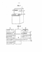
As Figuras 4A e 4B são vistas em corte verticais esquemáticas mostrando a configuração de um cassete de rejeição de acordo com o Exemplo Comparativo 1;Figures 4A and 4B are schematic vertical section views showing the configuration of a rejection cassette according to Comparative Example 1;
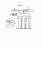
As Figuras 5A e 5B são vistas em corte verticais esquemáticas mostrando a configuração de um cassete de rejeição de acordo com o Exemplo Comparativo 2;Figures 5A and 5B are schematic vertical section views showing the configuration of a rejection cassette according to Comparative Example 2;
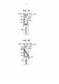
As Figuras 6A e 6B são vistas em corte verticais esquemáticas mostrando a configuração de um cassete de rejeição de acordo com o Exemplo Comparativo 3;Figures 6A and 6B are schematic vertical section views showing the configuration of a rejection cassette according to Comparative Example 3;
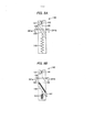
As Figuras 7A e 7B são vistas em corte verticais esquemáticas mostrando a configuração de um cassete de rejeição de acordo com o Exemplo Comparativo 4;Figures 7A and 7B are schematic vertical section views showing the configuration of a rejection cassette according to Comparative Example 4;
As Figuras 8A e 8B são vistas em corte verticais esquemáticas mostrando a configuração de um cassete de rejeição de acordo com o Exemplo Comparativo 5;Figures 8A and 8B are schematic vertical section views showing the configuration of a rejection cassette according to Comparative Example 5;
A Figura 9 é uma vista em corte vertical esquemática mostrando a configuração de um cassete de rejeição de acordo com o Exemplo Comparativo 6;Figure 9 is a schematic vertical section view showing the configuration of a rejection cassette according to Comparative Example 6;
A Figura 10 é uma vista em corte vertical esquemática mostrando a configuração de um cassete de rejeição de acordo com a primeira modalidade da presente invenção;Figure 10 is a schematic vertical cross-sectional view showing the configuration of a rejection cassette according to the first embodiment of the present invention;
As Figura 11A, 11B e 11C são vistas em corte verticais esquemáticas mostrando uma transição de estado durante o acúmulo de notas no cassete de rejeição mostrado na Figura 10;Figures 11A, 11B and 11C are seen in schematic vertical sections showing a state transition during the accumulation of notes in the rejection cassette shown in Figure 10;
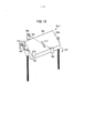
A Figura 12 é uma vista em perspectiva esquemática mostrando o cassete de rejeição mostrado na Figura 10;Figure 12 is a schematic perspective view showing the rejection cassette shown in Figure 10;
A Figura 13 é uma vista em perspectiva esquemática mostrando um estado em que as notas são acumuladas no cassete de rejeição mostrado na Figura 10;Figure 13 is a schematic perspective view showing a state in which notes are accumulated in the rejection cassette shown in Figure 10;
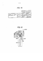
A Figura 14 mostra combinação de lógicas de resultados de detecção de sensores na primeira modalidade para utilização em um determinador determinando se ou não as notas são acumuladas;Figure 14 shows the combination of logic of sensor detection results in the first modality for use in a determiner determining whether or not the grades are accumulated;
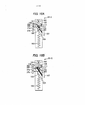
A Figura 15 é uma vista em corte vertical esquemática mostrando a configuração de um cassete de rejeição de acordo com a segunda modalidade da presente invenção;Figure 15 is a schematic vertical cross-sectional view showing the configuration of a rejection cassette according to the second embodiment of the present invention;
As Figuras 16A, 16B e 16C são vistas em corte verticais esquemáticas mostrando uma transição de estado durante o acúmulo de notas no cassete de rejeição mostrado na Figura 15;Figures 16A, 16B and 16C are seen in schematic vertical section showing a state transition during the accumulation of notes in the rejection cassette shown in Figure 15;
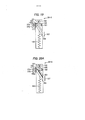
A Figura 17 é uma vista em perspectiva esquemática mostrando o cassete de rejeição em um caso em que um sensor de nota adicional é disposto na modalidade mostrada na Figura 15;Figure 17 is a schematic perspective view showing the rejection cassette in a case where an additional note sensor is arranged in the manner shown in Figure 15;
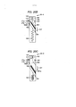
A Figura 18 é uma vista em perspectiva esquemática mostrando um estado em que notas são acumuladas no cassete de rejeição mostrado na Figura 17;Figure 18 is a schematic perspective view showing a state in which notes are accumulated on the rejection cassette shown in Figure 17;
A Figura 19 é uma vista em corte vertical esquemática mostrando a configuração de um cassete de rejeição de acordo com a terceira modalidade da presente invenção;Figure 19 is a schematic vertical cross-sectional view showing the configuration of a rejection cassette according to the third embodiment of the present invention;
As Figuras 20A, 20B e 20C são vistas em corte verticais esquemáticas mostrando uma transição de estado durante o acúmulo de notas no cassete de rejeição mostrado na Figura 19;Figures 20A, 20B and 20C are seen in schematic vertical section showing a state transition during the accumulation of notes in the rejection cassette shown in Figure 19;
A Figura 21 é uma vista em perspectiva esquemática mostrando o cassete de rejeição mostrado na Figura 19;Figure 21 is a schematic perspective view showing the rejection cassette shown in Figure 19;
A Figura 22 é uma vista em corte vertical esquemática mostrando a configuração de um cassete de rejeição de acordo com a quarta modalidade da presente invenção;Figure 22 is a schematic vertical cross-sectional view showing the configuration of a rejection cassette according to the fourth embodiment of the present invention;
A Figura 23 é uma vista em elevação esquemática mostrando notas acumuladas na posição horizontal, eFigure 23 is a schematic elevation view showing notes accumulated in a horizontal position, and
A Figura 24 é uma vista em elevação esquemática mostrando notas acumuladas na posição inclinada.Figure 24 is a schematic elevation view showing notes accumulated in the tilted position.
A seguir, modalidades de um dispositivo de acúmulo de meio de acordo com a presente invenção serão descritas em pormenor com referência às figuras anexas. No presente pedido, constituintes semelhantes são dados os mesmos números de referência e descrição repetitiva deles será evitada.In the following, modalities of a media accumulation device according to the present invention will be described in detail with reference to the accompanying figures. In the present application, similar constituents are given the same reference numbers and repetitive description of them will be avoided.
No presente pedido, uma pluralidade de constituintes tendo substancialmente a mesma configuração funcional pode ser distinguida uns dos outros por adição de diferentes indices para o mesmo número de referência. Por exemplo, como descrito mais adiante, a Figura 3 mostra três cassetes de armazenamento de nota 34 que têm substancialmente a mesma configuração funcional, o que é necessário para distingui-los um do outro, eles são designados com números de referência, por exemplo, 34A, 34B e 34C. Se não precisarem ser distinguidos um do outro, eles são designados com o cassete de armazenamento de nota 34 sem subscrito.In the present application, a plurality of constituents having substantially the same functional configuration can be distinguished from each other by adding different indices to the same reference number. For example, as described later, Figure 3 shows three note 34 storage cassettes that have substantially the same functional configuration, which is necessary to distinguish them from each other, they are designated with reference numbers, for example, 34A, 34B and 34C. If they do not need to be distinguished from each other, they are designated with the unsigned 34 note storage cassette.
Com as modalidades da invenção que serão descritas a seguir, meios a serem acumulados em uma tabela de acúmulo são notas, o que é simplesmente um exemplo e a invenção não deve ser limitada às modalidades. Por exemplo, o meio a ser acumulado na tabela de acúmulo pode ser cartões magnéticos ou cartões de IC (Circuito Integrado), tais como cartões de dinheiro ou cartões de crédito, livros de banco, titulos, ou bilhetes de transporte ou eventos, tais como bilhetes de transporte ferroviário, bilhetes de barco, bilhetes de embarque ou cupons.With the modalities of the invention that will be described below, means to be accumulated in an accumulation table are notes, which is simply an example and the invention should not be limited to the modalities. For example, the medium to be accumulated in the accumulation table can be magnetic cards or IC (Integrated Circuit) cards, such as cash cards or credit cards, bank books, titles, or transportation tickets or events, such as rail tickets, boat tickets, boarding tickets or coupons.
Referindo em primeiro lugar às Figuras 1 e 2, a configuração de um dispositivo de transação automático de acordo com uma modalidade da presente invenção será descrita. A Figura 1 é uma vista de aparência em perspectiva esquemática do dispositivo de transação automático de acordo com a modalidade da presente invenção. Como mostrado na figura, o dispositivo de transação automático linclui uma operação/tela 10, um manipulador de cartão/indicação 11, um manipulador de livro de banco 12, uma porta de entrada/saida de nota 13 e uma porta de entrada/saida de moeda 14.Referring first to Figures 1 and 2, the configuration of an automatic transaction device according to an embodiment of the present invention will be described. Figure 1 is a schematic perspective view of the automatic transaction device according to the embodiment of the present invention. As shown in the figure, the automatic transaction device includes an operation /
O dispositivo de transação automático 1 é instalado em vários locais, tais como bancos e estações, e nesta modalidade, é um dispositivo terminal ligado a um sistema de processamento central, tal como um servidor ou um computador hospedeiro de uma facilidade financeira sobre uma rede de telecomunicações 501, Figura 2, para fazer transações necessárias do cliente. Especificamente, a operação/tela 10 do dispositivo de transação automático 1 inclui funções de apresentação de uma tela de guiar uma transação para o cliente e de aceitar entradas por uma transação manual do cliente. À medida que a função de aceitar a entrada de transação, a operação/tela 10 pode ser implementada por, por exemplo, um painel de toque que detecta toques na tela aceitar entrada.The
O manipulador de cartão/indicação 11 é uma seção funcional que recebe ou descarrega um cartão magnético ou um cartão de circuito integrado, tal como um cartão bancário, isto é, um cartão de plástico, não representado, para uso em transação, e descarrega uma tira de papel, ou seja, indicação, não mostrada também, em que detalhes da transação são registrados. O manipulador de livro de banco 12 é uma seção funcional que recebe ou descarrega um livro de banco, não mostrado, para utilização na transação. A porta de entrada/saida de nota 13 é uma seção funcional que recebe ou ejeta notas. A porta de entrada/saida de moeda 14 é uma seção funcional que recebe ou ejeta moedas. A porta de entrada/saida de nota 13 e a porta de entrada/saida de moeda 14 são fornecidas com respectivas persianas, ambas não mostradas, que são movidas por um acionador ou acionadores para proteger mecanicamente contra o lado de fora.The card /
A Figura 2 é um diagrama de blocos funcional esquemático mostrando a configuração do dispositivo de transação automático 1 de acordo com a modalidade mostrada na Figura 1. Como mostrado na figura, o dispositivo de transação automático 1 inclui, além da operação/tela 10, manipulador de cartão/indicação 11, manipulador de livro de banco 12, porta de entrada/saida de nota 13 e porta de entrada/saida de moeda 14, um controlador 15, um dispositivo de disco rigido (HDD) 16, um console de manutenção 17, um autenticador de veia 18 e um comunicadorFigure 2 is a schematic functional block diagram showing the configuration of the
A operação/tela 10 inclui uma seção da tela que exibe uma tela de orientação das operações para o cliente, e uma seção de operação de cliente que detecta a manipulação do cliente. A função da seção de tela é implementada por, por exemplo, um dispositivo de tela de tubo de raios catódicos (CRT), um dispositivo de tela de cristal liquido (LCD) ou um dispositivo de diodo emissor de luz orgânico (OLED). A função da seção de operação de cliente é implementada por, por exemplo, um painel de toque ou um botão mecânico, não mostrados. No dispositivo de transação automático na modalidade imediata, as funções da seção de tela e a seção de operação de cliente são integradas umas com as outras, mas as funções da seção de tela e a seção de operação de cliente podem ser separadas umas das outras.Operation /
0 manipulador de cartão/indicação 11 é uma seção funcional que lê dados de um cartão magnético ou cartão de IC, como um cartão de dinheiro que o cliente apresenta, e imprime os detalhes da transação em uma tira de papel para emitir e descarregá-los como uma indicação de transação. O manipulador de livro de banco 12 é uma seção funcional que imprime o conteúdo da transação efetuada pelo dispositivo de transação automático 1 em um livro de banco inserido pelo cliente.The card /
A porta de entrada/saida de nota 13 é uma seção funcional que conta notas a serem retornadas ao cliente ou notas a serem retiradas em uma transação de retirada de acordo com as denominações de nota, e transfere notas para a posição onde o cliente pode ter as notas. A porta de entrada/saida de nota 13 também tem a função de fiscalizar as notas inseridas pelo cliente em uma transação de depósito, e contar as notas de acordo com as denominações de nota para armazenar as notas no dispositivo de transação automático 1.The
A porta de entrada/saida de moeda 14 é uma seção funcional que inspeciona moedas inseridas pelo cliente em uma transação de depósito, e conta as moedas de acordo com as denominações de moedas para armazenar as moedas no dispositivo de transação automático 1. A porta de entrada/saida de moeda 14 também tem uma função de contagem de moedas a serem retiradas em uma transação de retirada, e transfere as moedas para a posição em que o cliente pode ter as moedas.The coin input /
O controlador de 15 tem uma função de controle geral de geralmente controlar operações do dispositivo de transação automático 1 no todo. O controlador 15 inclui, por exemplo, funções de um controle de comunicação que controla a comunicação entre o comunicador 19 e um computador hospedeiro, não representado, e uma tela de controle que controla telas a serem exibidas na operação/tela 10. O controlador 15 inclui ainda um determinador 20, que é uma seção funcional que é sensivel aos resultados de sensor de um sensor de tabela de acúmulo 37 e um sensor de meio 38, descrito mais adiante, Figura 3 para determinar se ou não uma nota é colocada sobre uma tabela de acúmulo 164, Figura 10, em um cassete de rejeição 35. Detalhes do determinador 20 serão descritos mais tarde com referência à Figura 14.The controller 15 has a general control function of generally controlling operations of the
A unidade de disco rigido (HDD) 16 é um dispositivo de armazenamento que armazena sequências de programa de controle, arquivos e semelhantes, que são necessários para o funcionamento do dispositivo de transação automático 1.The hard disk drive (HDD) 16 is a storage device that stores control program sequences, files and the like, which are necessary for the operation of the
O console de manutenção 17 é uma interface para o funcionário, e tem as funções de exibição de informação, como falhas e problemas das respectivas seções deste dispositivo, e de aceitar uma operação do funcionário para lidar com falhas ou problemas dessas seções.The
O autenticador de veia 18 é um autenticador para confirmar a identificação pessoal. Na modalidade imediata, o cliente é identificado por leitura de um padrão de veia de uma palma do cliente e comparar o padrão de veia lido com um padrão de veia gravado antecipadamente no chip de IC, não mostrado, de um cartão de dinheiro inserido no manipulador de cartão/indicação 11 pelo cliente.The vein authenticator 18 is an authenticator for confirming personal identification. In immediate mode, the customer is identified by reading a vein pattern from a customer's palm and comparing the vein pattern read with a vein pattern recorded in advance on the IC chip, not shown, from a cash card inserted in the handler card /
O comunicador 19 é um interface com um computador hospedeiro para a transmissão e recepção de informação necessária para a transação de e para o computador hospedeiro através de uma linha de telecomunicações 501. As informações necessárias para a transação incluem, por exemplo, informações de cliente como um número de conta, uma senha e um saldo na conta do cliente, e informações sobre o conteúdo de transação, como o valor depositado ou retirado de dinheiro.
A seguir, referindo-se à Figura 3, descrição será feita sobre a configuração esquemática da porta de entrada/saida de nota 13 do dispositivo de transação automático 1. A Figura 3 é um diagrama de blocos funcional esquemática mostrando um exemplo da configuração da porta de entrada/saida de nota 13. Como pode ser visto a partir da figura, a porta de entrada/saida de nota 13 inclui uma seção servindo cliente 31, um discriminador 32, um armazenamento temporário 33, cassetes de armazenamento de nota 34A, 34B e 34C, cassete de rejeição 35, um depósito de nota deixada 36, um sensor de tabela de acúmulo 37, e um sensor de nota 38.Next, referring to Figure 3, a description will be made of the schematic configuration of the entry / exit door of
A seção servindo cliente 31 funciona como uma seção de entrada que separa as notas colocadas pelo cliente uma a uma em uma transação de depósito e transfere as notas, por exemplo, ao discriminador 32. A seção servindo cliente 31 recolhe notas a serem retornadas ao cliente ou notas a serem entregues ao cliente em uma transação de retirada.The
O discriminador 32 determina a denominação verdadeira/falsa e danos de notas transferidas da seção servindo cliente 31, bem como detecta uma falha de transferência e conta as notas cuja denominação foi estabelecida. No contexto, a denominação de nota é direcionada para a denominação de notas predominantemente circulando em uma região, como notas de 1000-ienes, 5000- ienes e 10000-ienes.The
O armazenamento temporário 33 é uma seção funcional que mantém temporariamente uma nota discriminada a ser aceitável pelo discriminador 32 em uma transação de depósito até o depósito ser estabelecido.
Os cassetes de armazenamento de nota 34A, 34B e 34C são armazenamentos que armazenam as notas inseridas na seção servindo cliente 31 pelo cliente. Notas a serem retiradas para o cliente também são armazenadas nos cassetes de armazenamento de nota 34A, 34B e 34C para serem retiradas do mesmo. 0 cassete de rejeição 35 é uma seção de armazenamento que armazena notas que o discriminador 32 determinou não serem transmitidas para o cliente em uma transação de retirada ou depósito, mas serem coletadas. Por exemplo, o discriminador 32 pode ser configurado para discriminar notas de denominação não fixa, denominação especificada, danificada ou suja como notas a serem recolhidas. As notas armazenadas no cassete de rejeição 35 serão retiradas e recolhidas pelo operador. Tal cassete de rejeição 35 e o dispositivo de transação automático 1 com tal cassete de rejeição 35 são específicos de caixas automáticos, que são adaptados para acumular notas como meio, e são um mero exemplo de dispositivo de acúmulo de meio de acordo com a presente invenção.Note
O depósito de nota deixada 36 é um armazenamento que armazena notas deixadas pelo cliente em uma transação de retirada ou depósito.The
O sensor de tabela de acúmulo 37 é um sensor óptico que detecta a tabela de acúmulo 164, Figura 10, no cassete de rejeição 35, em que notas serão acumuladas. O sensor de nota 38 é um sensor óptico que detecta se ou não uma nota é acumulada na tabela de acúmulo 164 no cassete de rejeição 35.The
A configuração especifica que detecta se ou não uma nota é colocada na tabela de acúmulo 164 no cassete de rejeição 35 vai ser descrita em comparação com exemplos comparativos. Em primeiro lugar, o cassete de rejeição que acumula um meio na sua posição horizontal irá ser descrito com referência às Figuras 4A a 5B.The configuration specifies that it detects whether or not a note is placed in the accumulation table 164 in the
A Figura 4A é uma vista em corte vertical esquemática mostrando a configuração de um cassete de rejeição 100 em conformidade com o Exemplo Comparativo 1. O cassete de rejeição 100 inclui um rolo de acionamento 101, um rolo ocioso 102, uma tabela de acúmulo 104, e uma mola de fase 103. A fim de determinar se ou não notas 301 são acumuladas no cassete de rejeição 100, Figura 4B, são fornecidos do lado de fora do cassete de rejeição 100 um detector de residue 201 na forma de um conjunto de emissor de luz 201a e sensor óptico 201b, e um detector de residue 202 na forma de um conjunto de emissor de luz 202a e sensor óptico 202b.Figure 4A is a schematic vertical cross-sectional view showing the configuration of a
Uma vez que o cassete de rejeição 100 é um cassete que é dedicado para a acúmulo, tal como descrito acima, e não alimenta notas acumuladas para fora, nenhum componente elétrico é fornecido em um espaço de acúmulo de meio 105, mas, como mostrado na Figura 4A, os detectores de residuo 201 e 202 são fornecidos no exterior do cassete de rejeição 100. Uma vez que o cassete de rejeição 100 pode armazenar uma nota dobrada, é necessário fornecer tal uma pluralidade de detectores de residuo 201 e 202 de modo a monitorar pontos plurais na tabela de acúmulo 104.Since the
No cassete de rejeição 100 no Exemplo Comparativo 1, as notas 301 são retiradas do caminho de transferência, não mostrado, pelo rolo de acionamento 101 e o rolo ocioso 102 no cassete 100 a ser acumulado na tabela de acúmulo 104. A tabela de acúmulo 104 é suportada pela mola de fase 103 e guiada por uma ranhura de deslizamento e um eixo, não ilustrado, a ser descido na direção de uma seta 107 pelo peso próprio das notas acumuladas 301, Figura 4B.In the
Os detectores de residuo 201 e 202 fornecidos no cassete de rejeição 100 formam respectivos caminhos ópticos 109 e 111 substancialmente na mesma direção que a direção de deslocamento da tabela de acúmulo 104, e são dispostos de modo que os caminhos ópticos 109 e 111 passem respectivos, buracos opticamente transparentes 113 e 115, que são fornecidos na tabela de acúmulo 104. Por conseguinte, quando a tabela de acúmulo 104 está localizada em qualquer posição na direção vertical 107, isto é, em qualquer altura, o caminho óptico 109 ou 111 é bloqueado enquanto as notas 301 são acumuladas na tabela de acúmulo 104, de modo que possa ser determinado que as notas 301 existem no cassete 100.Residue detectors 201 and 202 provided in the
A Figura 5A é uma vista em corte vertical esquemática mostrando a configuração de um cassete de rejeição 110 em conformidade com o Exemplo Comparativo 2. No caso em que a distância entre um detector de residuo 211 incluindo um emissor de luz 211a e um sensor óptico 211b e a tabela de acúmulo 104 é pequena, e a sensibilidade do detector de residuo 211 é suficiente, um prisma óptico 112 que refrata e guia caminho óptico 109 como mostrado na figura pode ser fornecido na tabela de acúmulo 104 de tal forma que o caminho óptico 109 é bloqueado pelas notas 301, como mostrado na Figura 5B. Isto pode reduzir o número e o espaço de montagem dos sensores, assim miniaturizando o dispositivo.Figure 5A is a schematic vertical cross-sectional view showing the configuration of a
Nos cassetes de rejeição 100 e 110 nos exemplos comparativos acima mencionados, a largura do cassete de rejeição, o que corresponde ao lado da nota 301 na direção de transferência, quando vista a partir da direção de acúmulo 107 das notas 301, isto é, a partir de cima nas figuras, deve ser equivalente à soma da largura do caminho de transferência, maior que uma das larguras do rolo de acionamento e o rolo ocioso, e a largura da seção de armazenamento de nota (tabela de acúmulo), o que restringiria a miniaturização.In
Por outro lado, no Exemplo comparativo 3, a tabela de acúmulo 124 tem sua superficie de acúmulo de nota inclinada, como mostrado na Figura 6A, e as notas 301 transferidas sobre um caminho de transferência, não representado, fornecidas acima de um cassete de rejeição 120 são acumuladas na vertical na posição inclinada do mesmo ao longo da superficie inclinada, como mostrado na Figura 6B. Isso permite que a largura do cassete de rejeição 120 que corresponde ao lado da nota na direção de transferência seja reduzida com menos restrições, implementando desse modo o cassete mais fino.On the other hand, in Comparative Example 3, the accumulation table 124 has its inclined note accumulation surface, as shown in Figure 6A, and the
Neste exemplo comparativo, um detector de residuo 221 incluindo um emissor de luz 221a e um sensor óptico 221b, bem como um detector de residuo 222 incluindo um emissor de luz 222a e um sensor óptico 222b são fornecidos de modo a formar os respectivos caminhos ópticos 109 e 111 na mesma direção que o movimento, isto é, direção de elevação e descida 107 da tabela de acúmulo 124. Assim, tal como no Exemplo Comparativo 1, em que a tabela de acúmulo 104 está localizada em qualquer posição na direção vertical 107, o caminho óptico 109 ou 111 é bloqueado enquanto as notas 301 são acumuladas na tabela de acúmulo 124, para que possa ser determinado que as notas 301 existem no cassete 120.In this comparative example, a residue detector 221 including a
Em um cassete de rejeição 130 no Exemplo Comparativo 4, como mostrado na Figura 7A, quando a distância entre o detector de residuo 231 incluindo um emissor de luz 231a e um sensor óptico 231b e uma tabela de acúmulo 134 é pequena, e a sensibilidade do detector de residuo 231 é suficiente, um prisma óptico 131 que refrata e guia o caminho óptico 109 é fornecido na tabela de acúmulo 134 de tal modo que o caminho óptico 109 é bloqueado pelas notas 301, como mostrado na Figura 7B. Isto pode reduzir o número e o espaço de montagem dos sensores, assim miniaturizando o dispositivo.In a
Os cassetes de rejeição finos 130 e 140 nos Exemplos Comparativos 3 e 4 são configurados de forma a acumular as- notas 301 na posição inclinada dos mesmos. Tal acúmulo na posição inclinada pode diminuir a largura necessária do espaço de acúmulo 105, implementando cassetes de rejeição mais finos. Agora, a altura do espaço de acúmulo 105, o que é necessário para o acúmulo na posição inclinada, será descrito em relação à altura necessária para o acúmulo na posição horizontal.The
Em primeiro lugar, a altura do espaço de acúmulo, a qual é necessária para o acúmulo na posição horizontal, será descrita com referência à Figura 23. Como pode ser visto a partir da figura, a altura do espaço de acúmulo, a qual é necessária para acumular as notas 301 na posição horizontal, é, obviamente, igual à altura H em que as notas 301 são acumuladas.First, the height of the accumulation space, which is necessary for the accumulation in the horizontal position, will be described with reference to Figure 23. As can be seen from the figure, the height of the accumulation space, which is necessary to accumulate
A altura do espaço de acúmulo 105, que é necessária quando o mesmo número de notas 301 como o exemplo mostrado na Figura 23 são acumuladas na posição de inclinada, será descrita com referência à Figura 24. Como pode ser visto a partir da figura, a altura do espaço de acúmulo, a qual é necessária quando as notas 301 são acumuladas em um ângulo de inclinação θ, encontra-se de acordo com a seguinte expressão (1) . [Expressão 1] Bsinθ + H/cosθ (D onde 0<θ<90 °, 0 < sinθ < 1 e 0 < cosθ < 0.The height of the
Assim, com cassetes de rejeição finos 120 e 130 que acumulam as notas 301 na posição inclinada, como o ângulo θ das notas 301 é maior, a largura do espaço de acúmulo 105 pode ser menor, mas a altura do espaço de acúmulo 105 precisa ser maior. Por conseguinte, com o cassete de rejeição fino 120 que é mais curto na direção de largura e mais longo na direção de altura, a distância entre o emissor de luz e o sensor óptico em cada um dos caminhos ópticos 109 e 111 formados pelos detectores de residuo 221 e 222, respectivamente, é maior do que no exemplo mostrado na Figura 4A pelos comprimentos representados por linhas tracejadas 109a e 111a na Figura 6A. Isto requer um sensor altamente sensivel caro, assim problematicamente levando a um aumento dos custos. Além disso, como um rolo de acionamento 121 e um rolo ocioso 122 existem entre o emissor de luz 221a e o sensor óptico 221b, o arranjo de posição do emissor de luz 221a e o sensor óptico 221b, que formam o caminho óptico 109 é restringido desvantaj osamente.Thus, with
Assim, no Exemplo Comparativo 5, mostrado na Figura 8A, o problema acima mencionado é resolvido por arranjar um detector de residuo 241 de modo a formar o caminho óptico 109 a partir de um emissor de luz 241a a um sensor óptico 241b em uma direção que é diferente da do movimento, ou seja, direção de elevação e descida 107 de uma tabela de acúmulo 144, Figura 8B. No cassete de rejeição 140, quando o caminho óptico 109 formado pelo detector de residuo 241 não é bloqueado pelas notas 301, é determinado que não existe nota. No entanto, dependendo do peso e da espessura das notas 301 acumuladas na tabela de acúmulo 144, a tabela de acúmulo 144 pode descer através de um comprimento excedendo um valor concebido, de modo que as notas 301, embora acumuladas conforme mostrado na Figura 8B, não interrompem o caminho óptico 109 para ser determinado que nenhuma nota existe.Thus, in Comparative Example 5, shown in Figure 8A, the aforementioned problem is solved by arranging a residue detector 241 so as to form the
Agora, um cassete de rejeição 150 em conformidade com o Exemplo Comparativo 6 mostrado na Figura 9 tem pluralidade de caminhos ópticos 109, 111, 118 e 119 formados em uma distância sobre a qual a tabela de acúmulo 144 move para assim detectar se ou não as notas 301 são acumuladas independente da posição a tabela de acúmulo 144 pode ocupar.Now, a
Alternativamente, um atuador não mostrado que levanta e baixa a tabela de acúmulo 144 pode ser adicionado, e a superficie superior das notas acumuladas mais acima 301 pode ser controlada em altura de forma a cair dentro do caminho óptico 109 formado pelo detector de residuo.Alternatively, an actuator not shown that raises and lowers the accumulation table 144 can be added, and the upper surface of the uppermost accumulated
No entanto, qualquer das configurações acima mencionadas no Exemplo Comparativo 6 desvantajosamente causa um aumento de custos e espaço do dispositivo.However, any of the configurations mentioned above in Comparative Example 6 disadvantageously causes an increase in costs and space of the device.
Assim, tendo em conta estas circunstâncias, o inventor fez a presente invenção. De acordo com modalidades da presente invenção, é detectada uma tabela de acúmulo sobre a qual notas são acumuladas é reduzida, tornando assim possivel determinar se é ou não meios são acumulados na tabela de acúmulo. Modalidades da presente invenção serão descritas em detalhe.Thus, taking these circumstances into account, the inventor made the present invention. According to the modalities of the present invention, an accumulation table is detected on which notes are accumulated is reduced, thus making it possible to determine whether or not means are accumulated in the accumulation table. Modalities of the present invention will be described in detail.
A Figura 10 é uma vista em corte vertical esquemática mostrando a configuração de um cassete de rejeição 35-1 de acordo com a primeira modalidade da presente invenção. A Figura 12 é uma vista em perspectiva esquemática do cassete de rejeição 35-1 de acordo com a modalidade mostrada na Figura 10. Como pode ser visto a partir das Figuras 10 e 12, o cassete de rejeição 35-1, de acordo com a modalidade instantânea inclui um rolo de acionamento 161, um rolo ocioso 162, uma mola de fase 163, uma tabela de acúmulo 164 e um detector de fase 165.Figure 10 is a schematic vertical cross-sectional view showing the configuration of a 35-1 rejection cassette according to the first embodiment of the present invention. Figure 12 is a schematic perspective view of the 35-1 rejection cassette according to the embodiment shown in Figure 10. As can be seen from Figures 10 and 12, the 35-1 rejection cassette according to Instantaneous mode includes a
Fora do cassete de rejeição 35-1, é fornecido um sensor de nota 38 incluindo um conjunto de emissor de luz 38a e sensor óptico 38b, que formam um caminho óptico 109 em uma direção intersectando a direção de deslocamento 107 da tabela de acúmulo 164 e detecta se ou não notas 301 são acumuladas. Fora do cassete de rejeição 35-1, proporciona- se também um sensor de tabela de acúmulo 37 incluindo emissor de luz 37a e sensor óptico 37b, que detectam também a descida da tabela de acúmulo 164. Constituintes do cassete de rejeição 35-1 serão descritos abaixo.Outside the rejection cassette 35-1, a
O rolo de acionamento 161 e o rolo ocioso 162 são membros de alimentação que sugam as notas 301 do caminho de transferência, não mostrado. A mola de fase 163 é um membro elástico que suporta a tabela de acúmulo 164. Embora a Figura 10 mostre uma mola de fase 163 como um exemplo do membro elástico, a presente invenção não está limitada a este exemplo. Por exemplo, uma pluralidade de molas pode ser fornecida como membros elásticos suportando a tabela de acúmulo 164. Além disso, embora a Figura 10 mostre exemplarmente a mola como um membro elástico, um membro elástico deformável elasticamente dependendo da carga de notas pode ser usado.The
A tabela de acúmulo 164 tem a sua superficie inclinada 164a com respeito à direção de elevação e descida 107 da tabela de acúmulo 164. A superficie inclinada 164a pode ser suficiente para suportar pelo menos parcialmente as notas acumuladas 301, Figura 11A, isto é, pode ser parcialmente aberta ou reticulada. De preferência, a superficie inclinada 164a forma uma superficie plana. As notas 301, Figura 13, sugadas pelo rolo de acionamento 161 e o rolo ocioso 162 são acumuladas na superficie inclinada 164a. Como as notas 301 são acumuladas na tabela de acúmulo 164, a mola de fase 163 é comprimida pelo peso das notas acumuladas 301. Mais especificamente, como as notas 301 são acumuladas na tabela de acúmulo 164, a tabela dβ' acúmulo 164 apoiada pela mola de fase 163 desce na direção da seta 107 com a compressão da mola de fase 163.The accumulation table 164 has its inclined
Como mostrado na Figura 12, o detector de fase 165 é fixado na tabela de acúmulo 164 em tal posição, fora da região em que as notas 301 serão acumuladas, para não interferir com o caminho óptico 109 formado pelo sensor de nota 38. Assim, o detector de fase 165 desloca-se na direção de elevação e descida 107, juntamente com a tabela de acúmulo 164. O detector de fase 165 é fornecido em uma posição em que um caminho óptico 117 formado pelo sensor de tabela de acúmulo 37 é bloqueado pela tabela de acúmulo 164, quando é levantada acima de uma altura predeterminada, isto é, posição predeterminada na direção de elevação e descida 107, da tabela de acúmulo 164. A posição predeterminada pode ser, por exemplo, uma posição inicial da tabela de acúmulo 164, ou uma altura tomada quando as notas 301 são dificilmente acumuladas.As shown in Figure 12, the
Tal como descrito acima, o cassete de rejeição 35-1 de acordo com a presente modalidade está disposto, como mostrado na Figura 12, de tal modo que, quando a tabela de acúmulo 164 eleva acima da posição predeterminada, o detector de fase 165 fornecido na tabela de acúmulo 164 bloqueia o caminho óptico 117 formado pelo sensor de tabela de acúmulo 37. Por outro lado, quando a tabela de acúmulo 164 desce abaixo da posição predeterminada, o detector de fase 165 desce em conjunto com a tabela de acúmulo 164, resultando em que o caminho óptico 117 formado pelo sensor de tabela de acúmulo 37 não é bloqueado pelo detector de fase 165. Como descrito acima, dependendo se é ou não o caminho óptico 117 formado pelo sensor de tabela de- acúmulo 37 está bloqueado pelo detector de fase 165, pode ser determinado se ou não a tabela de acúmulo 164 desce abaixo da posição predeterminada.As described above, the rejection cassette 35-1 according to the present embodiment is arranged, as shown in Figure 12, in such a way that, when the accumulation table 164 rises above the predetermined position, the
O sensor de nota 38 inclui, como descrito acima, o emissor de luz 38a e o sensor óptico 38b. O emissor de luz 38a e o sensor óptico 38b são, como se mostra na Figura 12, opostos um ao outro através da tabela de acúmulo 164. Como pode ser visto a partir da figura, quando nenhuma nota 301 é acumulada na tabela de acúmulo 164, que está localizada na posição mais acima na distância de elevação e descida, isto é, a posição inicial, o caminho óptico 109 formado a partir do emissor de luz 38 através do sensor óptico 38b passa através de uma fenda óptica 113 formada na tabela de acúmulo 164. Em contraste, como mostrado na Figura 13, quando as notas 301 são acumuladas na tabela de acúmulo 164, o caminho óptico 109 formado a partir do emissor de luz 38a através do sensor óptico 38b é bloqueado pelas notas 301, enquanto a tabela de acúmulo 164 está localizada acima da posição predeterminada. Como descrito acima, o cassete de rejeição 35-1 é configurado de tal forma que, quando o detector de fase 165 bloqueia o caminho óptico 117 formado pelo sensor de tabela de acúmulo 37, o sensor de nota 38 pode detectar que as notas 301 são acumuladas na tabela de acúmulo 164. Apesar da tabela de acúmulo 164 ter pelo menos uma parte sua, isto é, a fenda óptica 113 na modalidade presente, opticamente transparente, a tabela de acúmulo inteira 164 pode ser transparente.The
Na modalidade mostrada na Figura 2, o determinador 20 utiliza os resultados de detecção do sensor de tabela de acúmulo 37 e o sensor de meio 38 para determinar se ou não as notas 301 são acumuladas na tabela de acúmulo 164 do cassete de rejeição 35-1. Referindo à Figura 14, a função de determinação do determinador 20 será descrita especificamente a seguir.In the modality shown in Figure 2,
A Figura 14 mostra os resultados de detecção do sensor de tabela de acúmulo 37 e o sensor de nota 38 e lógicas de determinação do determinador 20. Na modalidade imediata, visto que os sensores 37 e 38 são sensores ópticos, quando feixes de luz 109 e 111 emitidos dos emissores de luz 37a e 38b, respectivamente, são recebidos pelos sensores ópticos 37b e 38b, os resultados de detecção mostram "brilho", e quando os caminhos ópticos 109 e 111 são bloqueados pelas notas 301 e o detector de fase 165, respectivamente, mostram os resultados de detecção "escuro".Figure 14 shows the detection results of the
Como pode ser visto a partir da figura 14, o determinador 20 determina que as notas 301 são acumuladas na tabela de acúmulo 164 quando o resultado de detecção do sensor de tabela de acúmulo 37 mostra "brilho" ou o resultado de detecção do sensor de nota 38 mostra "escuro". Em outras palavras, o determinador 20 determina que as notas 301 são acumuladas na tabela de acúmulo 164, quando o sensor de tabela de acúmulo 37 detecta que a tabela de acúmulo 164 desce abaixo da posição predeterminada ou o sensor de nota 38 detecta que as notas 301 são acumuladas.As can be seen from figure 14,
Por outro lado, quando os resultados de detecção do sensor de tabela de acúmulo 37 e sensor de nota 38 mostram "escuro" e "brilho", respectivamente, o determinador 20 determina que nenhuma nota 301 está acumulada na tabela de acúmulo 164. Em outras palavras, quando o sensor de tabela de acúmulo 37 detecta que a tabela de acúmulo 164 está localizada acima da posição predeterminada, e o sensor de nota 38 não detecta que as notas 301 são acumuladas, o determinador 20 determina que nenhuma nota 301 é acumulada na tabela de acúmulo 164.On the other hand, when the detection results of the
A seguir, referindo-se às Figuras 11A, 11B e 11C, descrição será feita em uma transição de estado durante o acúmulo das notas 301 no cassete de rejeição 35-1, ou seja, um processo de descer a tabela de acúmulo 164 será descrito. Essas figuras são vistas esquemáticas em corte vertical mostrando especificamente a transição de estado durante o acúmulo das notas 301 no cassete de rejeição 35- 1.In the following, referring to Figures 11A, 11B and 11C, description will be made in a state transition during the accumulation of
Quando nenhuma nota 301 é acumulada na tabela de acúmulo 164 do cassete de rejeição 35-1, como mostrado na Figura 10, a tabela de acúmulo 164 é levantada para a sua posição inicial pela mola de fase 163. Depois disso, quando as notas 301 são acumuladas na tabela de acúmulo 164, como mostrado na Figura 11A, o caminho óptico 109 formado pelo sensor de nota 38 é bloqueado pelas notas 301. Se a tabela de acúmulo 164 desce mais ou menos devido ao peso das notas acumuladas 301, desde que a tabela de acúmulo 164 localiza- se acima da posição predeterminada, o caminho óptico 109 formado pelo sensor de tabela de acúmulo 37 é então bloqueado pelo detector de fase 165. Neste momento, uma vez que os resultados de detecção de ambos os sensores de tabela de acúmulo 37 e 38 mostram o sensor de nota "escuro", o determinador 20 determina que as notas sejam acumuladas na tabela de acúmulo 164 de acordo com a relação de lógica representada na Figura 14.When no
Em seguida, como mostrado na Figura 11B, quando as notas 301 são ainda acumuladas na tabela de acúmulo 164, a tabela de acúmulo 164 desce devido ao peso das notas 301, e o caminho óptico 117 formado pelo sensor de tabela de acúmulo 37 se torna não bloqueado pelo detector de fase 165 fornecido na tabela de acúmulo 164, ao passo que o caminho óptico 109 formado pelo sensor de nota 38 é ainda bloqueado pelas notas 301. Assim, uma vez que os resultados de detecção do sensor de tabela de acúmulo 37 e 38 mostram o sensor de nota "brilho" e "escuro", respectivamente, o determinador 20 determina que as notas 301 são acumuladas na tabela de acúmulo 164 de acordo com a relação de lógica representada na Figura 14.Then, as shown in Figure 11B, when notes 301 are still accumulated in the accumulation table 164, the accumulation table 164 goes down due to the weight of the
No entanto, dependendo do peso ou espessura das notas 301, por exemplo, quando as notas 301 estão molhadas, como mostrado na Figura 11C, a tabela de acúmulo 164 pode ser reduzida ainda mais a partir da sua posição normal e, assim, o caminho óptico 109 formado pelo sensor de nota 38 pode tornar-se não bloqueado pelas notas 301. No entanto, neste caso, uma vez que os resultados de detecção de ambos os sensores da tabela de acúmulo 37 e o sensor de nota 38 mostram "brilho", o determinador 20 determina que as notas 301 são acumuladas na tabela de acúmulo 164 de acordo com a relação de lógica mostrada na Figura 14.However, depending on the weight or thickness of the 301 banknotes, for example, when the 301 banknotes are wet, as shown in Figure 11C, the accumulation table 164 can be reduced further from its normal position and thus the path optical 109 formed by the
No entanto, quando o operador remove todas as notas 301 do cassete de rejeição 35-1, o peso de nota torna-se zero, e a tabela de acúmulo 164 é elevada a um batente, não mostrado, pela força de repulsão da mola de fase 163 e retorna à sua posição inicial. Na posição inicial, como mostrado na Figura 10, o caminho óptico 117 formado pelo sensor de tabela de acúmulo 37 é bloqueado pelo detector de fase 165. No entanto, o caminho óptico 109 formado pelo sensor de nota 38 não é bloqueado pelas notas 301. Assim, desde que o resultado de detecção do sensor de tabela de acúmulo 37 e sensor de nota 38 mostre "escuro" e "brilho", respectivamente, o determinador 20 determina que nenhuma nota 301 está acumulada na tabela de acúmulo 164 de acordo com a relação de lógica mostrada na Figura 14.However, when the operator removes all
Em resumo, na modalidade imediata, é detectado se ou não a tabela de acúmulo 164 desce abaixo da posição predeterminada dependendo se ou não o caminho óptico 117 formado pelo sensor de tabela de acúmulo 37 é bloqueado pelo detector de fase 165. Na modalidade, quando a tabela de acúmulo 164 desce abaixo da posição predeterminada, o determinador 20 determina que as notas existem em qualquer caso. Dependendo do peso das notas 301, no entanto, quando a tabela de acúmulo 164 não desce abaixo da posição predeterminada, as notas 301 podem ser acumuladas na tabela de acúmulo 164, como mostrado na Figura 11A. Assim, o sensor de nota 38 é configurado de modo a determinar se ou não as notas 301 são acumuladas na tabela de acúmulo 164, pelo menos quando a tabela de acúmulo 164 está localizada acima da posição predeterminada. Pode, assim, ser determinado mais corretamente se ou não as notas 301 são acumuladas.In summary, in the immediate mode, it is detected whether or not the accumulation table 164 falls below the predetermined position depending on whether or not the
Na modalidade imediata, os caminhos ópticos 109 e 111 dos sensores 37, 38 podem ser formados em uma direção que é diferente da direção de elevação e descida 107 da tabela de acúmulo 164, caso em que o determinador 20 pode corretamente determinar se ou não as notas 301 são acumuladas, independentemente da posição da tabela de acúmulo 164, ou o estado de acúmulo de nota.In the immediate mode, the
De acordo com a presente modalidade, se ou não as notas acumuladas 301 são acumuladas na tabela de acúmulo 164 pode ser corretamente determinado com um pequeno número de sensores sem fornecer, tal como no Exemplo Comparativo 6 mostrado na Figura 9, sensores plurais 251 na direção de elevação e descida 107 da tabela de acúmulo 144, reduzindo assim os custos de todo o dispositivo.According to the present modality, whether or not the accumulated
Na presente modalidade, uma vez que o caminho óptico 109 do sensor não necessita ser paralelo à elevação e descida, isto é, direção de deslocamento 107 da tabela de acúmulo 164, os sensores podem ser aplicados ao cassete fino 120, Figura 6A, como no Exemplo Comparativo 3, em que as notas são acumuladas na posição inclinada, a distância entre os sensores não será estendida. Por isso, um sensor de baixo custo pode ser utilizado em vez de um sensor de longa distância caro.In the present modality, since the
Na modalidade imediata, uma vez que o caminho óptico 109 do sensor pode ser formado em uma direção que é diferente da direção de elevação e inferior 107 da tabela de acúmulo 164, o caminho óptico do sensor não é afetado pelo rolo de acionamento 161 e o rolo ocioso 162, e, por conseguinte, o sensor pode ser livremente disposto em posição.In the immediate mode, since the
Bem, a Figura 15 é uma vista em corte vertical esquemática mostrando a configuração de um cassete de rejeição 35-2 de acordo com a segunda modalidade da presente invenção. Como mostrado na figura, o cassete de rejeição 35-2 de acordo com a modalidade instantânea tem primeiro e segundo prismas 171 e 173 além do rolo de acionamento 161, o rolo ocioso 162, a mola de fase 163, a tabela de acúmulo 164 e o detector de fase 165.Well, Figure 15 is a schematic vertical cross-sectional view showing the configuration of a 35-2 rejection cassette according to the second embodiment of the present invention. As shown in the figure, the rejection cassette 35-2 according to the instantaneous mode has first and
De um lado do cassete de rejeição 35-2, ou seja, no lado esquerdo na Figura 15, um sensor de nota 38 incluindo um conjunto de emissor de luz 38a e sensor óptico 38b é fornecido de modo a formar o caminho óptico 109 na direção intersectando com a direção de deslocamento 107 da tabela de acúmulo 164 para detectar se ou não as notas 301 são acumuladas. Fora do cassete de rejeição 35-1, o sensor de tabela de acúmulo 37 é fornecido o qual inclui um conjunto de emissor de luz 37a e um sensor óptico 37b para detectar a tabela de acúmulo 164 sendo descida. Os componentes serão descritos a seguir.On one side of the rejection cassette 35-2, that is, on the left side in Figure 15, a
Uma vez que o rolo de acionamento 161, o rolo ocioso 162, a mola de fase 163, a tabela de acúmulo 164 e o detector de fase 165 podem ser os mesmos que os da primeira modalidade, a descrição dos mesmos não será repetida.Since the
O primeiro prisma 171 é um elemento óptico que tem o seu lado em formato como ilustração, e refrata o feixe de luz 109 emitido a partir do emissor de luz 38a do sensor de nota 38 para guiar este último para o sensor óptico 38b. O segundo prisma 173 também é um elemento óptico que tem o seu lado em formato como ilustração, e refrata o feixe de luz 111 a partir do emissor de luz 37a do sensor de tabela de acúmulo 37 para guiar este último para o sensor óptico 37b. Os prismas 171 e 173 podem ser fixamente fornecidos em uma posição que não move com o movimento da tabela de acúmulo 164, por exemplo, no alojamento do cassete 35-2.The
Como descrito acima, na modalidade imediata, o fornecimento dos prismas 171 e 173 que guiam os feixes de luz 109 e 111, respectivamente, torna os dois sensores 37 e 38 dispostos de um lado do cassete de rejeição 35-2. Isso faz o espaço de montagem para os sensores 37 e 38 diminuídos em aproximadamente metade do que na primeira modalidade, reduzindo ainda mais o tamanho de todo o dispositivo. O sensor de nota 38, incluindo assim o primeiro prisma 171, sozinho faz os dois caminhos ópticos 109 serem formados de modo a intersectar com a direção de deslocamento 107 da tabela de acúmulo 164. Isto pode reduzir ainda mais o número de sensores, reduzindo assim os custos de todo o dispositivo.As described above, in the immediate embodiment, the provision of the
O determinador 20 mostrado na Figura 2 utiliza os resultados de detecção do sensor de tabela de acúmulo 37 e o sensor de meio 38 para determinar se ou não as notas 301 são acumuladas na tabela de acúmulo 164 do cassete de rejeição 35-2. A relação de lógica representada na Figura 14 é aplicada à lógica de determinação do determinador 20 como ela é.The
Em seguida, uma transição de estado durante o acúmulo das notas 301 no cassete de rejeição 35-2, ou seja, descer a tabela de acúmulo 164 será descrito com referência às Figuras 16A, 16B e 16C. Essas figuras são vistas em corte verticais esquemáticas mostrando especificamente a transição de estado durante o acúmulo das notas 301 no cassete de rejeição 35-2. Quando nenhuma nota é acumulada, a tabela de acúmulo 164 do cassete de rejeição 35-2 é levantada até a posição inicial pela mola de fase 163, como mostrado na Figura 15.Then, a state transition during the accumulation of
Em seguida, como mostrado na Figura 16A, quando as notas 301 são acumuladas na tabela de acúmulo 164, o caminho óptico 109 formado pelo sensor de nota 38 é bloqueado pelas notas 301. Quando a tabela de acúmulo 164 desce mais ou menos, devido ao peso das notas acumuladas 301, e mantém-se acima da posição predeterminada, o caminho óptico 117 formado pelo sensor de tabela de acúmulo 37 é bloqueado pelo detector de fase 165. Neste momento, uma vez que os resultados de detecção de ambos os sensores de tabela de acúmulo 37 e sensor de nota 38 mostram "escuro", o determinador 20 determina que as notas 301 são acumuladas na tabela de acúmulo 164 de acordo com a relação de lógica representada na Figura 14.Then, as shown in Figure 16A, when notes 301 are accumulated in the accumulation table 164, the
Depois disto, como mostrado na Figura 16B, quando as notas 301 são ainda acumuladas na tabela de acúmulo 164, a tabela de acúmulo 164 desce devido ao peso das notas 301, e o caminho óptico 117 formado pelo sensor de tabela de acúmulo 37 torna-se desbloqueado pelo detector de fase 165 fornecido na tabela de acúmulo 164. No entanto, como mostrado na figura, o caminho óptico 109 formado pelo sensor de nota 38 é ainda bloqueado pelas notas 301. Assim, os resultados de detecção do sensor de tabela de acúmulo 37 e o sensor de nota 38 mostram "brilho" e "escuro", respectivamente, de modo que o determinador 20 determina que as notas são acumuladas na tabela de acúmulo 164 de acordo com a relação de lógica mostrada na Figura 14.After that, as shown in Figure 16B, when notes 301 are still accumulated in the accumulation table 164, the accumulation table 164 goes down due to the weight of the
Tal como na modalidade descrita anterior, de acordo com o peso ou espessura das notas 301, por exemplo, quando as notas são molhadas 301, como mostrado na Figura 16C, a tabela de acúmulo 164 pode ser descida ainda mais a partir da sua posição normal e, assim, o caminho óptico 109 formado pelo sensor de nota 38 pode tornar-se não bloqueado pelas notas 301. No entanto, neste caso, uma vez que os resultados de detecção de ambos o sensor de tabela de acúmulo 37 e sensor de nota 38 mostram "brilho", o determinador 20 determina que as notas são acumuladas na tabela de acúmulo 164 de acordo com a relação de lógica representada na Figura 14.As in the modality described above, according to the weight or thickness of the
Agora, quando o operador remove todas as notas 301 do cassete de rejeição 35-2, o peso de nota torna-se zero, e a tabela de acúmulo 164 é elevada para o batente, não mostrado, pela força de repulsão da mola de fase 163 e volta para a posição inicial. Na posição inicial, como mostrado na Figura 15, o caminho óptico 117 formado pelo sensor de tabela de acúmulo 37 é bloqueado pelo detector de fase 165 que o caminho óptico 109 formado pelo sensor de nota 38 não é bloqueado pelas notas 301. Assim, o resultado de detecção do sensor de tabela de acúmulo 37 mostra "escuro", ou o resultado de detecção do sensor de nota 38 mostra "brilho", de modo que o determinador 20 determina que nenhuma nota é acumulada na tabela de acúmulo 164 de acordo com a relação de lógica mostrada na Figura 14.Now, when the operator removes all
Em resumo, na presente modalidade, a provisão dos prismas 171 e 173 que guiam os caminhos ópticos 109 e 117, respectivamente, permite os sensores 38 e 37 serem dispostos em um dos lados do cassete de rejeição 35-2. Isso faz o espaço de montagem de sensor ser reduzido cerca de metade do que na modalidade descrita anterior, permitindo redução adicional do tamanho de dispositivo.In summary, in the present embodiment, the provision of
Ainda que a modalidade mostrada nas Figuras 15 e 16 tenha os prismas 171 e 173 que refratam ou refletem os feixes de luz 105 e 117, respectivamente, isto é apenas um exemplo, e a presente invenção não está limitada a tal exemplo. Em lugar dos prismas, outros membros de guia de luz que refletem e guiam a luz, tais como placas refletoras e fibras ópticas, podem ser aplicados.Although the embodiment shown in Figures 15 and 16 has
Na modalidade imediata, o sensor de nota 38 pode ser fornecido no plural, de modo a formar uma pluralidade de caminhos ópticos que correspondem ao tamanho das notas 301 a serem detectadas. Por exemplo, como mostrado na Figura 17, o cassete de rejeição 35-2 é fornecido com dois conjuntos de sensores de notas 38 para formar quatro caminhos ópticos 109.In the immediate mode, the
No exemplo mostrado na Figura 17, os caminhos ópticos 109 passando através da tabela de acúmulo 164 são fornecidos em alturas diferentes um do outro. Assim, como mostrado na Figura 18, mesmo quando uma nota quebrada ou dobrada 301a é colocada na tabela de acúmulo 164, a nota 301a pode ser detectada uma vez que pelo menos um dos caminhos ópticos 109 formados pelo sensor de nota 38 é interrompido.In the example shown in Figure 17,
A Figura 19 é uma vista em corte vertical esquemática mostrando a configuração de um cassete de rejeição 35-3 de acordo com uma terceira modalidade da presente invenção. A Figura 21 é uma vista em perspectiva esquemática do cassete de rejeição 35-3 de acordo com esta modalidade. Como pode ser visto a partir das Figuras 19 e 21, o cassete de rejeição 35-3 tem um prisma 181 em adição ao rolo de acionamento 161, o rolo ocioso 162, a mola de fase 163 e a tabela de acúmulo 164. O rolo de acionamento 161, rolo ocioso 162, mola de fase 163 e tabela de acúmulo 164 podem ser os mesmos que nas modalidades acima mencionadas..Figure 19 is a schematic vertical cross-sectional view showing the configuration of a 35-3 rejection cassette according to a third embodiment of the present invention. Figure 21 is a schematic perspective view of the 35-3 rejection cassette according to this embodiment. As can be seen from Figures 19 and 21, the rejection cassette 35-3 has a
O prisma 181 é configurado de modo a refratar o feixe de luz 117 emitido a partir do emissor de luz 37a do sensor de tabela de acúmulo 37 e guiar este último para o sensor óptico 37b, e é fixamente fornecido em tal ponto que não se move com o movimento da tabela de acúmulo 164, por exemplo, o alojamento do cassete 35-3.The
Na modalidade imediata, entre o cassete de rejeição 35-3 e o sensor de tabela de acúmulo 37 uma persiana 182 é fornecida. A persiana 182 é geralmente feita de um material de bloqueio de luz opticamente opaco, que bloqueia o caminho óptico 117, mas tem sua parte cortada em um orificio através óptico 182a que permite o caminho óptico 117 formado pelo sensor de tabela de acúmulo 37 passar através do mesmo.In immediate mode, between the rejection cassette 35-3 and the
A persiana 182 é disposta de modo a engatar com a tabela de acúmulo 164, para levantar e descer em conjunto com a tabela de acúmulo 164. A persiana 182 pode ser configurada para elevar e baixar ao longo de uma ranhura de deslizamento, não mostrada, ou rodar em torno do seu eixo de rotação. Em qualquer caso, como mostrado na Figura 21, quando a tabela de acúmulo 164 está localizada acima da posição predeterminada, a persiana 182 é levantada pela tabela de acúmulo 164. Neste estado, o caminho óptico 117 formado pelo sensor de tabela de acúmulo 37 passa através do orificio 182a fornecido na persiana 182 e uma fenda 113 fornecida na tabela de acúmulo 164. Quando as notas 301 são acumuladas na tabela de acúmulo 164, o caminho óptico 117 passando através do orificio 182a fornecido na persiana 182 é bloqueado pelas notas 301. Como descrito acima, o sensor de tabela de acúmulo 37 na presente modalidade* também funciona como o sensor de nota 38.The blind 182 is arranged to engage with the accumulation table 164, for raising and lowering together with the accumulation table 164. The blind 182 can be configured to raise and lower along a sliding groove, not shown, or rotate around its axis of rotation. In any case, as shown in Figure 21, when the accumulation table 164 is located above the predetermined position, the blind 182 is raised by the accumulation table 164. In this state, the
Quando a tabela de acúmulo 164 desce, devido ao peso próprio das notas acumuladas 301, a persiana 182 também desce em conjunto com a tabela de acúmulo 164, para uma posição em que a persiana bloqueia o caminho óptico 117, e cessará lá. Especificamente, como mostrado na Figura 21, a persiana 182 é fornecida com uma protrusão 183, e quando a persiana 182 desce em conjunto com a tabela de acúmulo 164, a protrusão 183 engata com um batente 401. Isto impede uma maior descida da persiana 182.When the accumulation table 164 goes down, due to the proper weight of the accumulated
O determinador 20 mostrado na Figura 2 utiliza o resultado de detecção do sensor de tabela de acúmulo 37 que tem a configuração acima mencionada para determinar se ou não as notas 301 são acumuladas na tabela de acúmulo 164 do cassete de rejeição 35-3. Uma vez que o sensor 37 na modalidade instantânea é o sensor óptico, quando o feixe de luz 117 emitido a partir do emissor de luz 37a pé recebido pelo sensor óptico 37b, o resultado de detecção mostra "brilho", ao passo que, quando o caminho óptico 117 é bloqueado pela as notas 301 ou a persiana 182, o resultado de detecção mostra "escuro".The
Assim, quando o resultado de detecção do sensor de tabela de acúmulo 37 mostra "brilho", o determinador 20 determina que nenhuma nota 301 é acumulada na tabela de acúmulo 164. Este é o caso em que o sensor de tabela de acúmulo 37 detecta que a tabela de acúmulo 164 está localizada acima da posição predeterminada, ou não consegue detectar o acúmulo das notas 301. Em ambos os casos, o determinador 20 irá determinar que nenhuma nota é acumulada na tabela de acúmulo 164.Thus, when the detection result of the
Por outro lado, quando o resultado de detecção do sensor de tabela de acúmulo 37 mostra "escuro", o determinador 20 determina que as notas 301 são acumuladas na tabela de acúmulo 164. Este é o caso em que o sensor de tabela de acúmulo 37 detecta que a tabela de acúmulo 164 desce abaixo da posição predeterminada, ou detecta as notas 301 acumuladas. Em ambos os casos, o determinador 20 irá determinar que as notas são acumuladas na tabela de acúmulo 164.On the other hand, when the detection result of the
Em seguida, uma transição de estado enquanto as notas 301 são acumuladas no cassete de rejeição 35-3 e o cassete 35-3 desce será descrita com referência às Figuras 20A, 20B e 20C. Essas figuras são vistas em corte verticais esquemáticas especificamente mostrando a transição de estado durante o acúmulo das notas 301 no cassete de rejeição 35-3.Then, a state transition while
Quando nenhuma nota 301 é acumulada na tabela de acúmulo 164 do cassete de rejeição 35-3, como mostrado na Figura 19, a tabela de acúmulo 164 é levantada para a sua posição inicial pela mola de fase 163. Depois disso, quando as notas 301 são acumuladas na tabela de acúmulo 164, como mostrado na Figura 20A, o caminho óptico 117 formado pelo sensor de tabela de acúmulo 37 é bloqueado pelas notas 301. Neste momento, uma vez que o sensor de tabela de acúmulo 37 mostra "escuro", o determinador 20 determina que nenhuma nota é acumulada na tabela de acúmulo 164.When no
Em seguida, como mostrado na Figura 20B, quando as notas 301 são adicionalmente acumuladas na tabela de acúmulo 164, a tabela de acúmulo 164 desce, devido ao peso das notas 301, e a persiana 182 também desce em conjunto com a tabela de acúmulo 164. Isso faz o caminho óptico 117 formado pelo sensor de tabela de acúmulo 37 ser bloqueado pela persiana 182. Neste momento, uma vez que o resultado de detecção do sensor de tabela de acúmulo 37 mostra "escuro", o determinador 20 determina que nenhuma nota 301 é acumulada na tabela de acúmulo 164.Then, as shown in Figure 20B, when notes 301 are additionally accumulated in the accumulation table 164, the accumulation table 164 goes down, due to the weight of the
Agora, como mostrado na Figura 20C, dependendo do peso ou espessura das notas 301a, por exemplo, quando as notas são molhadas, a tabela de acúmulo 164 pode ainda ser descida a partir da posição normal mostrada na Figura 20B. Neste caso, embora a persiana 182 também desça em conjunto com a tabela de acúmulo 164, a protrusão 183 fornecida na persiana 182 engata com o batente 401, tal como descrito acima, de modo que a persiana 182 deixa de descer em uma altura em que a persiana 182 bloqueia o caminho óptico 117 formado pelo sensor de tabela de acúmulo 37. Por conseguinte, como mostrado na Figura 20C, o caminho óptico 117 formado pelo sensor de tabela de acúmulo 37 é bloqueado pela persiana 182. Neste momento, uma vez que o sensor de tabela de acúmulo 37 mostra "escuro", o determinador 20 determina que nenhuma nota 301 é acumulada na tabela de acúmulo 164.Now, as shown in Figure 20C, depending on the weight or thickness of the
Em seguida, quando o operador remove completamente as notas 301 do cassete de rejeição 35-3, o peso de nota torna-se zero, e a tabela de acúmulo 164 é levantada para a sua posição inicial pela mola de fase 163 novamente. Na posição inicial, como mostrado na Figura 19, o caminho óptico 117 formado pelo sensor de tabela de acúmulo 37 não está bloqueado. Neste momento, uma vez que o resultado de detecção do sensor de tabela de acúmulo 37 mostra "brilho", o determinador 20 determina que nenhuma nota 301 é acumulada na tabela de acúmulo 164.Then, when the operator completely removes the
Em resumo, na modalidade imediata, a persiana 182 trabalhando com à tabela de acúmulo 164 é arranjada. Isto permite o sensor óptico único 37 ser usado para mais corretamente determinar se ou não as notas 301 são acumuladas. Assim, o número de sensores é reduzido, permitindo as interligações e o tamanho de placas de circuito a serem reduzidos, implementando desse modo um dispositivo completamente reduzido em tamanho e custo.In summary, in the immediate modality, the blind 182 working with the accumulation table 164 is arranged. This allows the single
Na primeira e segunda modalidades descritas anteriormente, quando o resultado de detecção do sensor de tabela de acúmulo 37 mostra "escuro", o determinador 20 determina que a tabela de acúmulo é localizada acima da posição predeterminada. No entanto, a presente invenção não está limitada a essas modalidades especificas. Por exemplo, dependendo da configuração do cassete de rejeição 35, o determinador 20 pode determinar que a tabela de acúmulo 164 está localizada acima da posição predeterminada quando o resultado de detecção do sensor de tabela de acúmulo 37 mostra "brilho". Assim, uma quarta modalidade será mostrada na Figura 22, em que os prismas 191 podem ser ligados à tabela de acúmulo 164 de modo que o determinador 20 determina que a tabela de acúmulo 164 está localizada acima da posição predeterminada quando o resultado de detecção do sensor de tabela de acúmulo 37 mostra "brilho".In the first and second modalities described above, when the detection result of the
Com referência à Figura 22, o cassete de rejeição 35-4 de acordo com a quarta modalidade tem um prisma 191 em adição ao rolo de acionamento 161, o rolo ocioso 162, a mola de fase 163 e a tabela de acúmulo 164. O rolo de acionamento 161, rolo ocioso 162, mola de fase 163 e tabela de acúmulo 164 podem ser os mesmos que nas modalidades acima mencionadas.Referring to Figure 22, the rejection cassette 35-4 according to the fourth embodiment has a
O prisma 191 refrata o feixe de luz 117 emitido a partir do emissor de luz 37a do sensor de tabela de acúmulo 37 para guiar este último para p sensor óptico 37b. O prisma 191 está ligado à tabela de acúmulo 164, de modo a mover-se com o movimento da tabela de acúmulo 164, em uma posição onde o prisma 191 orienta o feixe de luz 117 emitido a partir do emissor de luz 37a para o sensor óptico 37b quando a tabela de acúmulo 164 está localizada acima da posição predeterminada.
Uma vez que o sensor 37 de acordo com a quarta modalidade é um sensor óptico, quando o feixe de luz 117 emitido a partir do emissor de luz 37a é recebido pelo sensor óptico 37b, o resultado de detecção do sensor 37 mostra "brilho", ao passo que quando o feixe de luz 117 não é recebido, o resultado de detecção do sensor 37 mostra "escuro". Assim, no cassete de rejeição 35-4 de acordo com a quarta modalidade, quando a tabela de acúmulo 164 está localizada acima da posição predeterminada, o prisma 191 orienta o feixe de luz 117 emitido a partir do emissor de luz 37a para o sensor óptico 37b, de modo que o resultado de detecção do sensor de tabela de acúmulo 37 mostra "brilho". O resultado de detecção do sensor de tabela de acúmulo 37 mostrando assim "brilho" faz com o determinador 20 determinar que a tabela de acúmulo 164 está localizada acima da posição predeterminada.Since the
Embora a presente invenção tenha sido descrita com referência a modalidades particulares ilustrativas, ela não deve ser limitada pelas modalidades. É para ser apreciado que os peritos na arte podem alterar ou modificar as modalidades sem se afastar do escopo e do espirito da presente invenção.Although the present invention has been described with reference to particular illustrative modalities, it should not be limited by the modalities. It is to be appreciated that those skilled in the art can alter or modify the modalities without departing from the scope and spirit of the present invention.
Por exemplo, nas modalidades acima descritas, os sensores ópticos são utilizados como o sensor de tabela de acúmulo 37 e o sensor de nota 38. No entanto, a presente invenção não está limitada a este exemplo. Em lugar de ou em adição aos sensores ópticos, sensores confiando em outros principies de funcionamento, tais como sensores de contacto ou sensores magnéticos, podem ser utilizados como sensor de tabela de acúmulo 37 e o sensor de nota 38.For example, in the embodiments described above, optical sensors are used as the
Apesar de um conjunto de sensores de nota 38 ser fornecido em modalidades, a presente invenção não está limitada a este exemplo. Por exemplo, um número necessário de sensores de nota, por exemplo, dois ou três conjuntos de sensores de notas, pode ser disposto de acordo com o tamanho e forma de notas alvo.Although a set of
Embora os sensores estejam dispostos do lado de fora do cassete de rejeição nas modalidades, os sensores podem ser apresentados dentro do cassete de rejeição.Although the sensors are arranged on the outside of the rejection cassette in the modalities, the sensors can be presented inside the rejection cassette.
Nas modalidades, a tabela de acúmulo 164 tem a superficie inclinada, em que as notas são acumuladas na posição inclinada. No entanto, a presente invenção não está limitada a este exemplo. Por exemplo, a superficie de acúmulo pode ter formado horizontal, em que as notas podem ser verticalmente acumuladas na posição horizontal. Também neste caso, a tabela de acúmulo sendo baixada pode ser detectada para determinar se ou não as notas são acumuladas na tabela de acúmulo.In the embodiments, the accumulation table 164 has an inclined surface, where the notes are accumulated in an inclined position. However, the present invention is not limited to this example. For example, the accumulation surface may have formed horizontally, in which notes can be vertically accumulated in a horizontal position. Also in this case, the accumulation table being downloaded can be detected to determine whether or not grades are accumulated in the accumulation table.
A revelação completa de Pedido de Patente Japonesa No. 2010-189233 depositado em 26 de Agosto 2010, incluindo a especificação, reivindicações, desenhos anexos e resumo da descrição, é aqui incorporada por referência na sua totalidade.The full disclosure of Japanese Patent Application No. 2010-189233 filed on August 26, 2010, including the specification, claims, attached drawings and summary of the description, is hereby incorporated by reference in its entirety.
Claims (10)
Applications Claiming Priority (3)
| Application Number | Priority Date | Filing Date | Title |
|---|---|---|---|
| JP2010-189233 | 2010-08-26 | ||
| JP2010189233A JP5440445B2 (en) | 2010-08-26 | 2010-08-26 | Media accumulator |
| PCT/JP2011/062503 WO2012026178A1 (en) | 2010-08-26 | 2011-05-31 | Medium accumulating device |
Publications (2)
| Publication Number | Publication Date |
|---|---|
| BR112012033696A2 BR112012033696A2 (en) | 2016-12-06 |
| BR112012033696B1 true BR112012033696B1 (en) | 2020-12-01 |
Family
ID=45723194
Family Applications (1)
| Application Number | Title | Priority Date | Filing Date |
|---|---|---|---|
| BR112012033696-7A BR112012033696B1 (en) | 2010-08-26 | 2011-05-31 | media accumulation device |
Country Status (6)
| Country | Link |
|---|---|
| US (1) | US8973916B2 (en) |
| JP (1) | JP5440445B2 (en) |
| CN (3) | CN104658098B (en) |
| BR (1) | BR112012033696B1 (en) |
| RU (2) | RU2532711C2 (en) |
| WO (1) | WO2012026178A1 (en) |
Families Citing this family (15)
| Publication number | Priority date | Publication date | Assignee | Title |
|---|---|---|---|---|
| JP6255695B2 (en) | 2012-10-05 | 2018-01-10 | 株式会社リコー | Non-aqueous photopolymerizable composition, inkjet ink, and ink cartridge |
| JP6102487B2 (en) * | 2013-05-10 | 2017-03-29 | 沖電気工業株式会社 | Medium storage apparatus and medium transaction apparatus |
| JP6060806B2 (en) * | 2013-05-10 | 2017-01-18 | 沖電気工業株式会社 | Medium storage apparatus and medium transaction apparatus |
| CN104123785A (en) * | 2014-07-18 | 2014-10-29 | 广州广电运通金融电子股份有限公司 | Sheet medium storing device |
| JP6439371B2 (en) * | 2014-10-17 | 2018-12-19 | 沖電気工業株式会社 | Medium accommodation apparatus and medium transaction apparatus |
| CN104537760B (en) * | 2014-12-19 | 2018-03-02 | 深圳怡化电脑股份有限公司 | Cash box, ATM and banknote state monitoring method |
| JP6459619B2 (en) * | 2015-02-24 | 2019-01-30 | 沖電気工業株式会社 | Medium storage and medium processing apparatus |
| CN105006060B (en) * | 2015-07-28 | 2019-10-11 | 深圳怡化电脑股份有限公司 | Paper money case, ATM and paper money case state monitoring method |
| US9875593B1 (en) * | 2015-08-07 | 2018-01-23 | Cummins-Allison Corp. | Systems, methods and devices for coin processing and coin recycling |
| JP6751535B2 (en) * | 2015-10-19 | 2020-09-09 | 日東電工株式会社 | Flat plate work cutting and recovery system, and flat plate work cutting and recovery method |
| US11395566B2 (en) | 2016-04-11 | 2022-07-26 | Gpcp Ip Holdings Llc | Sheet product dispenser |
| US11412900B2 (en) | 2016-04-11 | 2022-08-16 | Gpcp Ip Holdings Llc | Sheet product dispenser with motor operation sensing |
| CN109399260B (en) * | 2018-10-23 | 2020-11-03 | 山东叶华纸制品包装有限公司 | Material supply method for carton printing process |
| JP7405583B2 (en) | 2019-12-03 | 2023-12-26 | シャープ株式会社 | banknote storage device |
| WO2022029944A1 (en) * | 2020-08-05 | 2022-02-10 | 富士通フロンテック株式会社 | Paper sheet storage device and paper sheet handling device |
Family Cites Families (23)
| Publication number | Priority date | Publication date | Assignee | Title |
|---|---|---|---|---|
| JP2641275B2 (en) | 1988-11-28 | 1997-08-13 | 株式会社日立製作所 | Paper sheet stacking and feeding device |
| JPH02225238A (en) * | 1989-02-23 | 1990-09-07 | Hitachi Ltd | Detection of piling quantity of paper in paper handling device |
| JPH03105160A (en) * | 1989-09-18 | 1991-05-01 | Hitachi Ltd | Screw type freezer |
| JPH03105160U (en) * | 1990-02-16 | 1991-10-31 | ||
| JP3420787B2 (en) | 1992-08-03 | 2003-06-30 | 沖電気工業株式会社 | Conveyance medium detection device |
| JP3218812B2 (en) * | 1993-06-22 | 2001-10-15 | オムロン株式会社 | Paper storage amount detection device |
| US6145826A (en) * | 1997-10-27 | 2000-11-14 | Canon Kabushiki Kaisha | Image forming apparatus |
| JP3620967B2 (en) * | 1998-06-30 | 2005-02-16 | 沖電気工業株式会社 | Banknote storage box |
| RU2175210C2 (en) * | 1999-11-02 | 2001-10-27 | Российский Федеральный Ядерный Центр - Всероссийский Научно-Исследовательский Институт Экспериментальной Физики | Article storage apparatus |
| JP2001335236A (en) | 2000-05-25 | 2001-12-04 | Canon Inc | Sheet processing device and image forming device provided therewith |
| JP4160362B2 (en) * | 2002-10-30 | 2008-10-01 | グローリー株式会社 | Accumulator and circulating banknote deposit and withdrawal machine |
| JP2005015123A (en) | 2003-06-25 | 2005-01-20 | Canon Inc | Sheet conveying device |
| US6848688B1 (en) | 2003-09-08 | 2005-02-01 | Xerox Corporation | Automatically elevating sheet tamper and sheet input level for compiling large printed sets |
| JP4238193B2 (en) | 2004-05-18 | 2009-03-11 | 株式会社リコー | Paper folding apparatus and image forming apparatus |
| JP4446806B2 (en) * | 2004-06-16 | 2010-04-07 | 日立オムロンターミナルソリューションズ株式会社 | Banknote handling equipment |
| CN100562472C (en) | 2004-09-16 | 2009-11-25 | 株式会社理光 | Sheet processing apparatus and imaging device |
| JP4579296B2 (en) | 2005-08-05 | 2010-11-10 | グローリー株式会社 | Paper sheet storage and feeding device |
| RU2366789C1 (en) * | 2006-05-29 | 2009-09-10 | Федеральное государственное унитарное предприятие "Российский федеральный ядерный центр-Всероссийский научно-исследовательский институт технической физики имени академика Е.И. Забабахина" | Device for storage and distribution of objects |
| US7690637B2 (en) | 2007-02-01 | 2010-04-06 | Toshiba Tec Kabushiki Kaisha | Sheet processing apparatus and sheet processing method |
| JP5045164B2 (en) * | 2007-03-13 | 2012-10-10 | 沖電気工業株式会社 | Automatic banknote deposit and withdrawal machine |
| JP2009102096A (en) * | 2007-10-22 | 2009-05-14 | Ricoh Elemex Corp | Paper sheet post-processing device |
| JP5120226B2 (en) | 2008-11-20 | 2013-01-16 | 沖電気工業株式会社 | Media handling device |
| JP5267072B2 (en) * | 2008-11-25 | 2013-08-21 | 沖電気工業株式会社 | Banknote accumulation mechanism |
-
2010
- 2010-08-26 JP JP2010189233A patent/JP5440445B2/en active Active
-
2011
- 2011-05-31 CN CN201510017553.2A patent/CN104658098B/en active Active
- 2011-05-31 WO PCT/JP2011/062503 patent/WO2012026178A1/en active Application Filing
- 2011-05-31 US US13/807,911 patent/US8973916B2/en active Active
- 2011-05-31 CN CN201180032546.XA patent/CN102971244B/en active Active
- 2011-05-31 BR BR112012033696-7A patent/BR112012033696B1/en active IP Right Grant
- 2011-05-31 RU RU2012156273/08A patent/RU2532711C2/en active
- 2011-05-31 CN CN201410012383.4A patent/CN103778725B/en active Active
-
2014
- 2014-08-12 RU RU2014133185/08A patent/RU2584962C2/en active
Also Published As
| Publication number | Publication date |
|---|---|
| JP2012046301A (en) | 2012-03-08 |
| CN104658098A (en) | 2015-05-27 |
| CN102971244B (en) | 2016-01-27 |
| CN103778725A (en) | 2014-05-07 |
| US20130099442A1 (en) | 2013-04-25 |
| RU2014133185A (en) | 2016-03-10 |
| US8973916B2 (en) | 2015-03-10 |
| RU2584962C2 (en) | 2016-05-20 |
| RU2532711C2 (en) | 2014-11-10 |
| BR112012033696A2 (en) | 2016-12-06 |
| JP5440445B2 (en) | 2014-03-12 |
| RU2012156273A (en) | 2014-06-27 |
| CN104658098B (en) | 2018-02-02 |
| CN102971244A (en) | 2013-03-13 |
| WO2012026178A1 (en) | 2012-03-01 |
| CN103778725B (en) | 2016-10-12 |
Similar Documents
| Publication | Publication Date | Title |
|---|---|---|
| BR112012033696B1 (en) | media accumulation device | |
| JP5564915B2 (en) | Banknote deposit and withdrawal machine | |
| JP5919953B2 (en) | Drawer and medium transaction device | |
| JP2009023822A (en) | Paper sheet treating device | |
| WO2016059839A1 (en) | Medium accommodating device and medium transaction device | |
| KR102106865B1 (en) | Paper money storage cassette | |
| KR101467581B1 (en) | Appratus for receiving and dispensing notes in automated teller machine | |
| KR100603936B1 (en) | Shutter device and method for operating the shutter device | |
| KR101866992B1 (en) | Locking device for cassette push plate | |
| KR100722876B1 (en) | Method of rejecting bills in apparatus for drawing bills in a cash transaction machine | |
| KR101520493B1 (en) | Appratus for receiving and dispensing notes in automated teller machine | |
| JP5338503B2 (en) | Banknote handling equipment | |
| JP4774263B2 (en) | Interlock device and medium conveying device | |
| JP5258681B2 (en) | Banknote handling equipment | |
| JP6421665B2 (en) | Media processing device | |
| JP2015095023A (en) | Paper money detection device, light-emitting device, and automatic transaction device | |
| JP6070476B2 (en) | Rotating device and medium transaction device | |
| KR101940733B1 (en) | Banknote storage and financial device thereof | |
| WO2024075395A1 (en) | Medium transaction device and control method | |
| JP4248031B2 (en) | Coin deposit and withdrawal machine | |
| KR101284762B1 (en) | Coin containing module | |
| KR20200079918A (en) | Detecting apparatus of thickness and financial device having the same | |
| KR200391304Y1 (en) | Dispenser sensor structure of cash transaction machine | |
| JP4881962B2 (en) | Coin deposit / withdrawal device | |
| JP4881963B2 (en) | Automatic transaction equipment |
Legal Events
| Date | Code | Title | Description |
|---|---|---|---|
| B06F | Objections, documents and/or translations needed after an examination request according [chapter 6.6 patent gazette] | ||
| B06T | Formal requirements before examination [chapter 6.20 patent gazette] | ||
| B07A | Technical examination (opinion): publication of technical examination (opinion) [chapter 7.1 patent gazette] | ||
| B09A | Decision: intention to grant [chapter 9.1 patent gazette] | ||
| B16A | Patent or certificate of addition of invention granted |
Free format text: PRAZO DE VALIDADE: 20 (VINTE) ANOS CONTADOS A PARTIR DE 31/05/2011, OBSERVADAS AS CONDICOES LEGAIS. |