BR112012018010B1 - "set for securing tissue or a prosthetic element in an opening provided in a human or animal bone". opening provided in a human or animal bone - Google Patents
"set for securing tissue or a prosthetic element in an opening provided in a human or animal bone". opening provided in a human or animal bone Download PDFInfo
- Publication number
- BR112012018010B1 BR112012018010B1 BR112012018010-0A BR112012018010A BR112012018010B1 BR 112012018010 B1 BR112012018010 B1 BR 112012018010B1 BR 112012018010 A BR112012018010 A BR 112012018010A BR 112012018010 B1 BR112012018010 B1 BR 112012018010B1
- Authority
- BR
- Brazil
- Prior art keywords
- fastener
- anchoring
- graft
- opening
- bone
- Prior art date
Links
Images


Classifications
-
- A—HUMAN NECESSITIES
- A61—MEDICAL OR VETERINARY SCIENCE; HYGIENE
- A61B—DIAGNOSIS; SURGERY; IDENTIFICATION
- A61B17/00—Surgical instruments, devices or methods, e.g. tourniquets
- A61B17/56—Surgical instruments or methods for treatment of bones or joints; Devices specially adapted therefor
- A61B17/58—Surgical instruments or methods for treatment of bones or joints; Devices specially adapted therefor for osteosynthesis, e.g. bone plates, screws, setting implements or the like
- A61B17/68—Internal fixation devices, including fasteners and spinal fixators, even if a part thereof projects from the skin
- A61B17/84—Fasteners therefor or fasteners being internal fixation devices
- A61B17/86—Pins or screws or threaded wires; nuts therefor
- A61B17/8645—Headless screws, e.g. ligament interference screws
-
- A—HUMAN NECESSITIES
- A61—MEDICAL OR VETERINARY SCIENCE; HYGIENE
- A61B—DIAGNOSIS; SURGERY; IDENTIFICATION
- A61B17/00—Surgical instruments, devices or methods, e.g. tourniquets
- A61B17/56—Surgical instruments or methods for treatment of bones or joints; Devices specially adapted therefor
- A61B17/58—Surgical instruments or methods for treatment of bones or joints; Devices specially adapted therefor for osteosynthesis, e.g. bone plates, screws, setting implements or the like
- A61B17/68—Internal fixation devices, including fasteners and spinal fixators, even if a part thereof projects from the skin
- A61B17/686—Plugs, i.e. elements forming interface between bone hole and implant or fastener, e.g. screw
-
- A—HUMAN NECESSITIES
- A61—MEDICAL OR VETERINARY SCIENCE; HYGIENE
- A61B—DIAGNOSIS; SURGERY; IDENTIFICATION
- A61B17/00—Surgical instruments, devices or methods, e.g. tourniquets
- A61B17/04—Surgical instruments, devices or methods, e.g. tourniquets for suturing wounds; Holders or packages for needles or suture materials
- A61B17/0401—Suture anchors, buttons or pledgets, i.e. means for attaching sutures to bone, cartilage or soft tissue; Instruments for applying or removing suture anchors
-
- A—HUMAN NECESSITIES
- A61—MEDICAL OR VETERINARY SCIENCE; HYGIENE
- A61B—DIAGNOSIS; SURGERY; IDENTIFICATION
- A61B17/00—Surgical instruments, devices or methods, e.g. tourniquets
- A61B17/56—Surgical instruments or methods for treatment of bones or joints; Devices specially adapted therefor
- A61B17/58—Surgical instruments or methods for treatment of bones or joints; Devices specially adapted therefor for osteosynthesis, e.g. bone plates, screws, setting implements or the like
- A61B17/68—Internal fixation devices, including fasteners and spinal fixators, even if a part thereof projects from the skin
- A61B17/84—Fasteners therefor or fasteners being internal fixation devices
- A61B17/86—Pins or screws or threaded wires; nuts therefor
- A61B17/8625—Shanks, i.e. parts contacting bone tissue
-
- A—HUMAN NECESSITIES
- A61—MEDICAL OR VETERINARY SCIENCE; HYGIENE
- A61B—DIAGNOSIS; SURGERY; IDENTIFICATION
- A61B17/00—Surgical instruments, devices or methods, e.g. tourniquets
- A61B17/56—Surgical instruments or methods for treatment of bones or joints; Devices specially adapted therefor
- A61B17/58—Surgical instruments or methods for treatment of bones or joints; Devices specially adapted therefor for osteosynthesis, e.g. bone plates, screws, setting implements or the like
- A61B17/68—Internal fixation devices, including fasteners and spinal fixators, even if a part thereof projects from the skin
- A61B17/84—Fasteners therefor or fasteners being internal fixation devices
- A61B17/86—Pins or screws or threaded wires; nuts therefor
- A61B17/864—Pins or screws or threaded wires; nuts therefor hollow, e.g. with socket or cannulated
-
- A—HUMAN NECESSITIES
- A61—MEDICAL OR VETERINARY SCIENCE; HYGIENE
- A61F—FILTERS IMPLANTABLE INTO BLOOD VESSELS; PROSTHESES; DEVICES PROVIDING PATENCY TO, OR PREVENTING COLLAPSING OF, TUBULAR STRUCTURES OF THE BODY, e.g. STENTS; ORTHOPAEDIC, NURSING OR CONTRACEPTIVE DEVICES; FOMENTATION; TREATMENT OR PROTECTION OF EYES OR EARS; BANDAGES, DRESSINGS OR ABSORBENT PADS; FIRST-AID KITS
- A61F2/00—Filters implantable into blood vessels; Prostheses, i.e. artificial substitutes or replacements for parts of the body; Appliances for connecting them with the body; Devices providing patency to, or preventing collapsing of, tubular structures of the body, e.g. stents
- A61F2/02—Prostheses implantable into the body
- A61F2/08—Muscles; Tendons; Ligaments
- A61F2/0811—Fixation devices for tendons or ligaments
-
- A—HUMAN NECESSITIES
- A61—MEDICAL OR VETERINARY SCIENCE; HYGIENE
- A61B—DIAGNOSIS; SURGERY; IDENTIFICATION
- A61B17/00—Surgical instruments, devices or methods, e.g. tourniquets
- A61B17/56—Surgical instruments or methods for treatment of bones or joints; Devices specially adapted therefor
- A61B17/58—Surgical instruments or methods for treatment of bones or joints; Devices specially adapted therefor for osteosynthesis, e.g. bone plates, screws, setting implements or the like
- A61B17/68—Internal fixation devices, including fasteners and spinal fixators, even if a part thereof projects from the skin
- A61B17/84—Fasteners therefor or fasteners being internal fixation devices
- A61B17/86—Pins or screws or threaded wires; nuts therefor
- A61B17/8685—Pins or screws or threaded wires; nuts therefor comprising multiple separate parts
-
- A—HUMAN NECESSITIES
- A61—MEDICAL OR VETERINARY SCIENCE; HYGIENE
- A61B—DIAGNOSIS; SURGERY; IDENTIFICATION
- A61B17/00—Surgical instruments, devices or methods, e.g. tourniquets
- A61B2017/00831—Material properties
- A61B2017/00955—Material properties thermoplastic
-
- A—HUMAN NECESSITIES
- A61—MEDICAL OR VETERINARY SCIENCE; HYGIENE
- A61F—FILTERS IMPLANTABLE INTO BLOOD VESSELS; PROSTHESES; DEVICES PROVIDING PATENCY TO, OR PREVENTING COLLAPSING OF, TUBULAR STRUCTURES OF THE BODY, e.g. STENTS; ORTHOPAEDIC, NURSING OR CONTRACEPTIVE DEVICES; FOMENTATION; TREATMENT OR PROTECTION OF EYES OR EARS; BANDAGES, DRESSINGS OR ABSORBENT PADS; FIRST-AID KITS
- A61F2/00—Filters implantable into blood vessels; Prostheses, i.e. artificial substitutes or replacements for parts of the body; Appliances for connecting them with the body; Devices providing patency to, or preventing collapsing of, tubular structures of the body, e.g. stents
- A61F2/02—Prostheses implantable into the body
- A61F2/08—Muscles; Tendons; Ligaments
- A61F2/0805—Implements for inserting tendons or ligaments
-
- A—HUMAN NECESSITIES
- A61—MEDICAL OR VETERINARY SCIENCE; HYGIENE
- A61F—FILTERS IMPLANTABLE INTO BLOOD VESSELS; PROSTHESES; DEVICES PROVIDING PATENCY TO, OR PREVENTING COLLAPSING OF, TUBULAR STRUCTURES OF THE BODY, e.g. STENTS; ORTHOPAEDIC, NURSING OR CONTRACEPTIVE DEVICES; FOMENTATION; TREATMENT OR PROTECTION OF EYES OR EARS; BANDAGES, DRESSINGS OR ABSORBENT PADS; FIRST-AID KITS
- A61F2/00—Filters implantable into blood vessels; Prostheses, i.e. artificial substitutes or replacements for parts of the body; Appliances for connecting them with the body; Devices providing patency to, or preventing collapsing of, tubular structures of the body, e.g. stents
- A61F2/02—Prostheses implantable into the body
- A61F2/08—Muscles; Tendons; Ligaments
- A61F2/0811—Fixation devices for tendons or ligaments
- A61F2002/0847—Mode of fixation of anchor to tendon or ligament
- A61F2002/0858—Fixation of tendon or ligament between anchor and bone, e.g. interference screws, wedges
-
- A—HUMAN NECESSITIES
- A61—MEDICAL OR VETERINARY SCIENCE; HYGIENE
- A61F—FILTERS IMPLANTABLE INTO BLOOD VESSELS; PROSTHESES; DEVICES PROVIDING PATENCY TO, OR PREVENTING COLLAPSING OF, TUBULAR STRUCTURES OF THE BODY, e.g. STENTS; ORTHOPAEDIC, NURSING OR CONTRACEPTIVE DEVICES; FOMENTATION; TREATMENT OR PROTECTION OF EYES OR EARS; BANDAGES, DRESSINGS OR ABSORBENT PADS; FIRST-AID KITS
- A61F2/00—Filters implantable into blood vessels; Prostheses, i.e. artificial substitutes or replacements for parts of the body; Appliances for connecting them with the body; Devices providing patency to, or preventing collapsing of, tubular structures of the body, e.g. stents
- A61F2/02—Prostheses implantable into the body
- A61F2/08—Muscles; Tendons; Ligaments
- A61F2/0811—Fixation devices for tendons or ligaments
- A61F2002/0876—Position of anchor in respect to the bone
- A61F2002/0882—Anchor in or on top of a bone tunnel, i.e. a hole running through the entire bone
-
- A—HUMAN NECESSITIES
- A61—MEDICAL OR VETERINARY SCIENCE; HYGIENE
- A61F—FILTERS IMPLANTABLE INTO BLOOD VESSELS; PROSTHESES; DEVICES PROVIDING PATENCY TO, OR PREVENTING COLLAPSING OF, TUBULAR STRUCTURES OF THE BODY, e.g. STENTS; ORTHOPAEDIC, NURSING OR CONTRACEPTIVE DEVICES; FOMENTATION; TREATMENT OR PROTECTION OF EYES OR EARS; BANDAGES, DRESSINGS OR ABSORBENT PADS; FIRST-AID KITS
- A61F2210/00—Particular material properties of prostheses classified in groups A61F2/00 - A61F2/26 or A61F2/82 or A61F9/00 or A61F11/00 or subgroups thereof
- A61F2210/0085—Particular material properties of prostheses classified in groups A61F2/00 - A61F2/26 or A61F2/82 or A61F9/00 or A61F11/00 or subgroups thereof hardenable in situ, e.g. epoxy resins
Abstract
CONJUNTO PARA PRENDER TECIDO OU UM ELEMENTO PROTÉTICO EM UMA ABERTURA PROPORCIONADA EM UM OSSO HUMANO OU ANIMAL. A presente invenção refere-se a um enxerto (1) ou elemento protético adequado, por exemplo, para substituir um tendão ou ligamento que é preso em um túnel ósseo ou abertura cega com o auxílio de um prendedor (3). Em uma primeira etapa, o enxerto (1) ou elemento protético é encaixado por pressão no túnel ou abertura forçando o prendedor (3) na abertura ou posicionando o prendedor na abertura e, então, expandindo o mesmo, sendo que o prendedor (3) está em contato com o enxerto (1) ou elemento protético e com a parede óssea do túnel ou abertura cega. Em uma segunda etapa, o prendedor (3) é ancorado na parede óssea do túnel ou abertura cega. Em uma segunda etapa, o prendedor (3) é ancorado na parede óssea do túnel ou abertura cega com o auxílio de um material liquidificável que é liquefeito na proximidade da parede óssea em que o mesmo está em contato com o prendedor e fazendo com que o material liquefeito penetre na parede óssea. Para a segunda etapa, um elemento de ancoragem (6) que compreende o material liquidificável é avançado em relação ao prendedor (3) e a energia,(...).ASSEMBLY TO HOLD TISSUE OR A PROSTHETIC ELEMENT IN AN OPENING PROVIDED IN A HUMAN OR ANIMAL BONE. The present invention relates to a graft (1) or suitable prosthetic element, for example, to replace a tendon or ligament that is attached to a bone tunnel or blind opening with the aid of a fastener (3). In a first step, the graft (1) or prosthetic element is fitted by pressure in the tunnel or opening, forcing the fastener (3) into the opening or positioning the fastener in the opening and then expanding it, with the fastener (3) it is in contact with the graft (1) or prosthetic element and with the bone wall of the tunnel or blind opening. In a second step, the fastener (3) is anchored to the bone wall of the tunnel or blind opening. In a second step, the fastener (3) is anchored to the bone wall of the tunnel or blind opening with the help of a liquidizable material that is liquefied in the vicinity of the bone wall where it is in contact with the fastener and causing the liquefied material penetrates the bone wall. For the second stage, an anchor element (6) that comprises the liquefiable material is advanced in relation to the fastener (3) and the energy, (...).
Description
[0001] A invenção refere-se ao campo de cirurgia ortopédica e refere-se a um método para prender um tecido ou um elemento protético correspondente em uma abertura fornecida em um osso animal ou humano. A invenção refere-se, adicionalmente, a um prendedor que é adequado para o método.[0001] The invention relates to the field of orthopedic surgery and relates to a method for securing a tissue or a corresponding prosthetic element in an opening provided in an animal or human bone. The invention additionally relates to a fastener that is suitable for the method.
[0002] O tecido ou elemento protético a ser fixado, com a ajuda do método e prendedor de acordo com a invenção, em uma abertura fornecida em um osso animal ou humano tem a função de um tecido mole e é, em particular, um ligamento ou enxerto de tendão (por exemplo, enxerto osso-tendão-osso ou enxerto de tendão com pelo menos uma extremidade suturada) ou um ligamento artificial ou substituto de tendão ou substituto parcial para substituir ou fortalecer um tendão ou ligamento rompido ou de outra forma defeituoso, mas esse tecido também pode ser um tendão ou ligamento natural para ser reacoplado a um osso a partir do qual foi desacoplado por ferimento ou cirurgia. Isso significa que o tecido ou elemento protético correspondente é, em particular, um tecido mole, um enxerto de tecido mole ou um substituto de tecido mole ou substituto parcial, o qual pode, entretanto, quando este for preso ao osso, compreender um pedaço de um tecido ósseo ou de um material de substituição correspondente, o qual é acoplado ao tecido mole e que neste caso é preso na abertura. Uma ou ambas as extremidades do tecido ou elemento protético correspondente a ser preso podem ser fortalecidas ou, em particular, no caso de um enxerto que compreende uma pluralidade de filamentos podem ser retidas juntas por costura, em que as extremidades de sutura que se estende para longe do enxerto também podem ser usadas para o posicionamento e tensionamento do enxerto.[0002] The tissue or prosthetic element to be fixed, with the help of the method and fastener according to the invention, in an opening provided in an animal or human bone has the function of a soft tissue and is, in particular, a ligament or tendon graft (for example, bone-tendon-bone graft or tendon graft with at least one sutured end) or an artificial ligament or partial tendon or substitute to replace or strengthen a torn or otherwise defective tendon or ligament , but that tissue can also be a natural tendon or ligament to be re-coupled to a bone from which it was uncoupled by injury or surgery. This means that the corresponding prosthetic tissue or element is, in particular, a soft tissue, a soft tissue graft or a soft tissue substitute or partial substitute, which may, however, when attached to the bone, comprise a piece of a bone tissue or a corresponding replacement material, which is attached to the soft tissue and which in this case is trapped in the opening. One or both ends of the corresponding tissue or prosthetic element to be attached can be strengthened or, in particular, in the case of a graft comprising a plurality of filaments, they can be retained together by sewing, where the suture ends extending to away from the graft can also be used for graft positioning and tensioning.
[0003] A abertura fornecida no osso para prender é, em uma forma conhecida por si só, um túnel que leva através do osso ou uma abertura cega que se estende no interior do osso de uma superfície de osso e que compreende dentro do osso uma extremidade fechada. Essa abertura é fornecida, preferencialmente, por perfuração, mas também pode ser fornecida por, por exemplo, punção (por exemplo, punção ultrassónica), isto é, essa abertura terá, frequentemente, uma seção transversal não circular ou circular que permanece constante sobre a maioria da profundidade da abertura, mas isso não é uma condição para a invenção. A abertura também pode ser uma pluralidade de seções com seções transversais diferentes, pode ter uma forma cônica, ou pode ser um corte inferior, (por exemplo, feita por moagem a qual permite a produção de geometrias tridimensionais dentro da abertura).[0003] The opening provided in the bone for clamping is, in a way known per se, a tunnel that leads through the bone or a blind opening that extends within the bone of a bone surface and that comprises within the bone a closed end. This opening is preferably provided by perforation, but it can also be provided by, for example, punch (for example, ultrasonic punch), that is, that opening will often have a non-circular or circular cross section that remains constant over the most of the depth of the opening, but that is not a condition for the invention. The opening can also be a plurality of sections with different cross sections, it can have a conical shape, or it can be a lower cut, (for example, made by grinding which allows the production of three-dimensional geometries within the opening).
[0004] Uma aplicação exemplificativa do método e prendedor de acordo com a invenção é a substituição de um ligamento cruzado anterior rompido (ACL) em um joelho humano por um enxerto o qual é preso por um lado em uma abertura que se estende a partir do prato tibial e por outro lado em uma abertura que se estende da superfície articular da extremidade de fêmur distai.[0004] An exemplary application of the method and fastener according to the invention is the replacement of a ruptured anterior cruciate ligament (ACL) in a human knee with a graft which is attached on one side in an opening that extends from the tibial plate and on the other hand in an opening that extends from the articular surface of the distal femur end.
[0005] De acordo com o estado da técnica, um ligamento cruzado anterior rompido é substituído, por exemplo, por um enxerto, tal como, por exemplo, um enxerto de tendão patelar que compreende dois blocos de osso terminal, um enxerto de tendão jarrete (tendão semitendinoso, possivelmente combinado com tendão grácil), geralmente sendo sobradas e suturadas na região de extremidade, isto é, sendo que não compreende blocos de osso terminal, ou um enxerto de tendão de quadriceps, o qual é geralmente colhido com um bloco de osso terminal. Os enxertos nomeados são geralmente autoenxertos, mas também podem ser enxertos de doador (aloenxerto). Os enxertos de doador também podem ser feitos de tendões de aquiles. É proposto, adicionalmente, usar fitas sintéticas (no presente documento chamadas de “enxertos artificiais”) e material de tendão tratado adequadamente de animais abatidos (xenoenxertos), por exemplo, porcos. Os autoenxertos e aloenxerto nomeados podem, além disso, ser reforçados com material sintético e serem combinados com enxertos de osso ou substitutos de osso sintético.[0005] According to the state of the art, a ruptured anterior cruciate ligament is replaced, for example, by a graft, such as, for example, a patellar tendon graft comprising two blocks of terminal bone, a hock tendon graft (semitendinosus tendon, possibly combined with gracile tendon), usually being left over and sutured in the extremity region, that is, it does not comprise blocks of terminal bone, or a quadriceps tendon graft, which is usually harvested with a block of terminal bone. The named grafts are usually autografts, but they can also be donor grafts (allografts). Donor grafts can also be made from Achilles tendons. It is proposed, in addition, to use synthetic tapes (in this document called "artificial grafts") and tendon material properly treated from slaughtered animals (xenografts), for example, pigs. The named autografts and allografts can, in addition, be reinforced with synthetic material and be combined with bone grafts or synthetic bone substitutes.
[0006] As regiões de extremidade de todos os enxertos nomeados (autoenxertos, aloenxerto, xenoenxertos e enxertos artificiais) precisam ser presas na tíbia e fêmur, para cujo propósito, um túnel ou um orifício cego é fornecido em qualquer um dos dois ossos. O orifício cego se origina a partir da superfície articular e termina dentro do osso. O túnel tem uma primeira boca situada na superfície articular e uma segunda boca a qual não está situada na superfície articular, em que a primeira boca e porção de túnel adjacente podem ter uma seção transversal maior que a segunda boca e porção de túnel adjacente. Para prender o enxerto na abertura fornecida, uma pluralidade de tipos de prendedor é conhecida.[0006] The end regions of all named grafts (autografts, allografts, xenografts and artificial grafts) need to be attached to the tibia and femur, for whose purpose, a tunnel or blind hole is provided in either of the two bones. The blind hole originates from the joint surface and ends within the bone. The tunnel has a first mouth located on the articular surface and a second mouth which is not located on the articular surface, where the first mouth and the adjacent tunnel portion may have a larger cross section than the second mouth and the adjacent tunnel portion. To attach the graft to the provided opening, a plurality of types of fastener are known.
[0007] Um túnel permite prender em uma parede óssea interna do túnel (fixação interna) e/ou na proximidade da segunda boca de túnel (fixação externa), uma abertura cega somente permite fixação interna. De acordo com o estado da técnica, a fixação interna em uma abertura de osso é efetuada, por exemplo, com o auxílio de um parafuso de interferência, o qual é aparafusado no interior da abertura quando enxerto for posicionado nisto; com o auxílio de um elemento de encaixe por pressão não expansível ou mecanicamente expansível não rosqueado, o qual é forçado sem rotação no interior da abertura quando o enxerto é posicionado nisto ou junto com o enxerto; ou com o auxílio de um pino de cabeça cruzada o qual é implantado em um ângulo ao eixo geométrico da abertura e engata, por exemplo, uma extremidade dobrada do enxerto ou um laço de sutura anexado à extremidade de enxerto. Em aberturas cegas, a fixação interna também pode ser efetuada com o auxílio de um parafuso de osso que compreende uma seção de cabeça para a qual o enxerto é fixado (parafuso gancho) e o qual é aparafusado no fundo da abertura cega. A fixação interna em um túnel é geralmente completada ao fechar a segunda boca de túnel com um plugue de osso ou elemento protético semelhante. Diversos dispositivos e métodos para fixação interna são descritos, por exemplo, nas publicações US-5454811 e US-6099530 (ambas para Smith&Nephew), EP-0317406 (Laboureau), ou US-2009/222090 (Mayr).[0007] A tunnel allows it to be attached to an internal bone wall of the tunnel (internal fixation) and / or in the vicinity of the second tunnel mouth (external fixation), a blind opening only allows internal fixation. According to the state of the art, internal fixation in a bone opening is carried out, for example, with the aid of an interference screw, which is screwed into the opening when the graft is positioned in this; with the aid of a non-expandable or mechanically expandable non-threaded snap-in element, which is forced without rotation into the opening when the graft is positioned in this or with the graft; or with the aid of a crosshead pin which is implanted at an angle to the geometric axis of the opening and engages, for example, a folded end of the graft or a suture loop attached to the graft end. In blind openings, internal fixation can also be performed with the aid of a bone screw that comprises a head section to which the graft is attached (hook screw) and which is screwed into the bottom of the blind opening. Internal fixation in a tunnel is usually completed by closing the second tunnel mouth with a bone plug or similar prosthetic element. Various devices and methods for internal fixation are described, for example, in publications US-5454811 and US-6099530 (both for Smith & Nephew), EP-0317406 (Laboureau), or US-2009/222090 (Mayr).
[0008] A fixação externa (fixação na aérea de uma segunda boca de túnel não situada na superfície articular), de acordo com o estado da técnica, é efetuada, por exemplo, com o auxílio de um botão através do qual o enxerto dobrado ou um laço de sutura anexado a uma extremidade de enxerto é rosqueado e o qual é maior que a seção transversal da segunda boca, ou com o auxílio de um parafuso de osso ou elemento de âncora semelhante, o qual retém o enxerto ou extremidades de sutura anexadas a isto e é aparafusado ou impactado no interior do osso na proximidade da segunda boca de túnel. Tal fixação externa também é proposta para reforçar uma fixação interna dentro do túnel.[0008] External fixation (fixation in the air of a second tunnel mouth not located on the articular surface), according to the state of the art, is carried out, for example, with the aid of a button through which the graft is bent or a suture loop attached to a graft end is threaded and which is larger than the cross section of the second mouth, or with the aid of a bone screw or similar anchor element, which retains the attached graft or suture ends to this and is screwed or impacted inside the bone in the vicinity of the second tunnel mouth. Such an external fixation is also proposed to reinforce an internal fixation inside the tunnel.
[0009] Para uma fixação interna em um túnel de osso ou abertura cega com o auxílio de um prendedor tal como um parafuso de interferência ou um elemento de encaixe por pressão, o enxerto ou uma porção de extremidade do enxerto, respectivamente, é pressionada contra um lado da abertura, quando o prendedor ocupa o outro lado da abertura. Essa, assim chamada, fixação de enxerto externo é principalmente usada para enxertos de um filamento e para enxertos que compreendem a bloco de osso terminal, mas também pode ser usada para enxertos de multifilamentos. Para enxertos que compreendem dois ao, por exemplo, serem dobrados, o prendedor também pode ser posicionado entre os filamentos, separando-os um do outro, em que os filamentos separados são pressionados contra paredes opostas da abertura de osso. Tal fixação é chamada de fixação de enxerto interno. A fixação de enxerto interno também é usada para enxertos de quatro ou mais que quatro filamentos, em que os filamentos do enxerto são pressionados contra a parede da abertura de osso, de preferência substancial e regularmente espaçados ao redor do prendedor e em que, entre filamentos vizinhos, o prendedor pode ou não estar em contato com a parede óssea da abertura. A fixação de enxerto interno é proposta, em particular, para a extremidade de enxerto na qual o filamento ou filamentos são dobrados.[0009] For an internal fixation in a bone tunnel or blind opening with the aid of a fastener such as an interference screw or a pressure fitting element, the graft or an end portion of the graft, respectively, is pressed against one side of the opening, when the fastener occupies the other side of the opening. This so-called external graft fixation is mainly used for grafts of a filament and for grafts that comprise the terminal bone block, but it can also be used for multifilament grafts. For grafts that comprise two by, for example, being folded, the fastener can also be positioned between the filaments, separating them from each other, in which the separate filaments are pressed against opposite walls of the bone opening. Such fixation is called internal graft fixation. Internal graft fixation is also used for grafts of four or more than four filaments, in which the graft filaments are pressed against the bone opening wall, preferably substantially and regularly spaced around the fastener and where, between filaments neighbors, the fastener may or may not be in contact with the bone wall of the opening. Internal graft fixation is proposed, in particular, for the graft end at which the filament or filaments are folded.
[0010] A publicação WO 2006/023661 (Scandious Biomedical) revela um grande número de métodos conhecidos de fixação de ACL, em particular, fixação de enxerto interno com o auxílio de prendedores de encaixe por pressão os quais são, adicionalmente, presos no túnel de osso ou orifício cego.[0010] The publication WO 2006/023661 (Scandious Biomedical) discloses a large number of known methods of fixing ACL, in particular, fixing the internal graft with the aid of snap-on fasteners which are additionally attached to the tunnel of bone or blind hole.
[0011] A qualidade de fixações de enxerto mais internas é, em particular, dependente da interface entre o enxerto e o prendedor por um lado e entre o enxerto e a parede da abertura por outro lado, mas na maioria dos casos também é dependente da interface entre o prendedor e a parede da abertura, em que estabilidade primária boa é desejada em todas as interfaces nomeadas e estabilidade a longo prazo boa, em particular, na interface entre o enxerto e o tecido ósseo (integração boa do enxerto no tecido natural por crescimento de tecido natural após a operação de fixação). Observa-se que a qualidade de fixação é dependente, adicionalmente, da localização de fixação na abertura, em que fixação tão próxima da superfície articular parece ser vantajosa. Para encurtar convalescença, estabilidade primária boa é desejada, para estabilidade a longo prazo boa, crescimento de osso na abertura. Para permitir um máximo de crescimento de osso na abertura, parafusos de interferência e elementos de encaixe por pressão biorreabsorvíveis são propostos. Além disso, é importante que o prendedor cause tão pouco dano quanto possível ao enxerto nem quando está a ser implantado, nem mais tarde, e que o enxerto cause o mínimo possível de ampliação ou outro dano à boca da abertura, em particular, para o caso no qual essa boca está situada em uma superfície articular.[0011] The quality of more internal graft fixations is, in particular, dependent on the interface between the graft and the fastener on the one hand and between the graft and the opening wall on the other hand, but in most cases it is also dependent on the interface between the fastener and the opening wall, where good primary stability is desired at all named interfaces and good long-term stability, in particular, at the interface between the graft and bone tissue (good integration of the graft into the natural tissue by growth of natural tissue after the fixation operation). It is observed that the quality of fixation is additionally dependent on the location of fixation in the opening, in which fixation so close to the articular surface seems to be advantageous. To shorten convalescence, good primary stability is desired, for good long-term stability, bone growth in the opening. To allow maximum bone growth at the opening, interference screws and bioresorbable pressure fitting elements are proposed. In addition, it is important that the fastener causes as little damage as possible to the graft, either when it is being implanted, or later, and that the graft causes the least possible enlargement or other damage to the opening mouth, in particular, to the in which case that mouth is located on an articular surface.
[0012] As falhas mais comuns de métodos de fixação de tecido mole conhecidos são causadas por danificação de tecido ou enxerto através dos fios de parafusos de interferência os quais podem levar ao rompimento de enxerto ou tecido, deslizamento de enxerto ou tecido devido ao relaxamento de um encaixe por pressão correspondente, ou migração de prendedor no primeiro carregamento, por exemplo, devido à compressão de tecido ósseo em resposta a elementos de ancoragem tal como, por exemplo, alargamentos, os quais podem levar a perda de tensão no enxerto ou tecido mole.[0012] The most common failures of known soft tissue fixation methods are caused by tissue or graft damage through interference screw wires which can lead to graft or tissue disruption, graft or tissue slip due to relaxation of a corresponding pressure fitting, or fastener migration on the first load, for example, due to compression of bone tissue in response to anchoring elements such as, for example, enlargements, which can lead to loss of tension in the graft or soft tissue .
[0013] A fixação conhecida de ligamentos a não ser do ligamento cruzado anterior (enxerto ou elemento protético, ou reanexação de ligamento natural), de tendões (enxerto ou elemento protético, ou reanexação de tendão natural), ou de outros, principalmente tecidos moles (enxerto ou elemento protético, ou reparo) em uma abertura de osso fornecida para a fixação, com o auxílio de um prendedor é baseada nos mesmos princípios que as fixações conhecidas descritas brevemente usadas para prender enxertos de ACL em aberturas fornecidas na tíbia e fêmur. Tais fixações são, por exemplo, usadas em procedimentos cirúrgicos em relação ao tornozelo ou pé humano, tal como, por exemplo, reconstrução de tornozelo lateral, Transferência de tendão de (flexor longo dos dedos), transferência de tendão de FHL (flexor longo do hálux), ou flexor para transferência de tendão (segundo dedo); procedimentos cirúrgicos em relação à mão humana tal como, por exemplo, interposição de tendão de reconstrução de ligamento, reconstrução de ligamento escafolunato, reconstrução de ligamento colateral, ou reparo de UCL (ligamento colateral ulnar) do polegar (também conhecido como “polegar do caçador”); procedimentos cirúrgicos em relação ao cotovelo humano tal como, por exemplo, reparo de UCL (ligamento colateral ulnar), ou reparo de tendão de bíceps distai; ou procedimentos cirúrgicos em relação ao ombro humano tal como, por exemplo, reparo de tendão de bíceps proximal. Um exemplo adicional é o reparo de ligamentos cruzados craniais danificados ou rompidos (CCL) em juntas do joelho de cães, em particular, mas também de, por exemplo, gatos. O CCL é o ligamento de joelho mais comumente danificado em cachorro e o reparo nomeado é realizada, por exemplo, com o uso de faixas de náilon as quais são passadas ao redor do osso fabela na parte traseira do fêmur e são fixadas em um orifício na parte frontal da tíbia. A mesma que métodos de fixação conhecidos, a fixação de acordo com a invenção é adequada para todas as aplicações nomeadas.[0013] The known fixation of ligaments other than the anterior cruciate ligament (graft or prosthetic element, or reattachment of natural ligament), tendons (graft or prosthetic element, or reattachment of natural tendon), or others, mainly soft tissues (graft or prosthetic element, or repair) in a bone opening provided for fixation, with the aid of a fastener is based on the same principles as the known fixations described briefly used to attach ACL grafts to openings provided in the tibia and femur. Such fixations are, for example, used in surgical procedures in relation to the human ankle or foot, such as, for example, lateral ankle reconstruction, Tendon transfer (long flexor toes), transfer of FHL tendon (long flexor of the toe). hallux), or flexor for tendon transfer (second finger); surgical procedures in relation to the human hand such as, for example, interposition of tendon reconstruction ligament, reconstruction of scapholunate ligament, reconstruction of collateral ligament, or repair of UCL (ulnar collateral ligament) of the thumb (also known as "hunter's thumb" ”); surgical procedures in relation to the human elbow such as, for example, repair of UCL (ulnar collateral ligament), or repair of the distal biceps tendon; or surgical procedures in relation to the human shoulder such as, for example, repair of the proximal biceps tendon. An additional example is the repair of damaged or broken cranial cruciate ligaments (CCL) in knee joints of dogs, in particular, but also, for example, cats. The CCL is the knee ligament most commonly damaged in dogs and the named repair is performed, for example, with the use of nylon strips which are passed around the fabella bone at the back of the femur and are fixed in a hole in the frontal part of the tibia. The same as known fastening methods, the fastening according to the invention is suitable for all named applications.
[0014] O objetivo da invenção é criar um método e prendedor adicional para prender tecido ou um artificial elemento correspondente (para ser compreendido como: preensão de autoenxerto, aloenxerto, xenoenxerto, ou elemento protético correspondente que substitui o tecido natural, ou reparo de fixação de tecido natural) dentro de uma abertura (“fixação interna” dentro de um ou dentro de uma abertura cega) fornecida em um osso animal ou humano, em que método e prendedor, de acordo com a invenção, devem ser simples e adequados para número grande de tipos diferentes de tecidos e elemento protéticos bem como para um número grande de tipos diferentes de aplicações e técnicas de operação (em particular, cirurgia do tipo artroscópica) sem a necessidade de adaptação substancial. Em particular, os métodos e prendedores, de acordo com a invenção, devem ser adequados sem adaptação substancial para serem usados na cirurgia de substituição de ligamento cruzado anterior com o uso de qualquer tipo de enxerto (autoenxerto, aloenxerto, xenoenxerto ou enxerto artificial de um filamento, dois filamentos ou multifilamentos, com ou sem bloco de osso terminal ou parte de enxerto artificial correspondente e com ou sem porções de extremidade suturada).[0014] The purpose of the invention is to create an additional method and fastener for attaching tissue or a corresponding artificial element (to be understood as: autograft, allograft, xenograft, or corresponding prosthetic element that replaces natural tissue, or fixation repair of natural tissue) inside an opening (“internal fixation” inside one or inside a blind opening) provided in an animal or human bone, in which method and fastener, according to the invention, must be simple and suitable for number large number of different types of tissues and prosthetic elements as well as for a large number of different types of applications and operating techniques (in particular, arthroscopic surgery) without the need for substantial adaptation. In particular, the methods and fasteners, according to the invention, must be suitable without substantial adaptation to be used in anterior cruciate ligament replacement surgery with the use of any type of graft (autograft, allograft, xenograft or artificial graft from a filament, two filaments or multifilaments, with or without a terminal bone block or corresponding artificial graft part and with or without portions of the sutured end).
[0015] Os objetos nomeados são alcançados pelo método e prendedor conforme definidos nas reivindicações anexas.[0015] The named objects are reached by the method and fastener as defined in the attached claims.
[0016] A fixação produzida com o método e prendedor, de acordo com a invenção, é uma fixação “interna” (o prendedor é posicionado no túnel ou abertura cega e prende o tecido na parede de dentro da abertura) e é basicamente uma combinação de encaixar por pressão o enxerto na abertura com o uso de um prendedor o qual trava o enxerto contra uma primeira porção da parede da abertura e ancoragem subsequente do prendedor em uma segunda porção da parede da abertura ao estabelecer uma conexão de encaixe positivo entre a âncora e essa segunda porção de parede. Isso significa que o encaixe por pressão e o encaixe positivo são efetuados um após o outro, separados localmente entre si e completamente independentes entre si.[0016] The fixation produced with the method and fastener, according to the invention, is an “internal” fixation (the fastener is positioned in the tunnel or blind opening and fastens the fabric to the wall inside the opening) and is basically a combination to snap the graft into the opening by using a fastener which locks the graft against a first portion of the opening wall and subsequently anchoring the fastener to a second portion of the opening wall by establishing a positive fitting connection between the anchor and this second wall portion. This means that the press fit and the positive fit are carried out one after the other, separated locally from each other and completely independent from each other.
[0017] A conexão de encaixe por pressão é alcançada em uma forma conhecida por si só com o uso de um prendedor dimensionado para ser forçado na abertura (dimensionamento correspondente do prendedor e abertura) ou com o uso de um prendedor o qual é posicionado na abertura e é então expandido, em que a força ou posicionamento do prendedor na abertura é realizado seja quando o tecido ou elemento artificial a ser preso já está posicionado na abertura ou junto com isso e em que a força ou posicionamento sem rotação do prendedor é preferencial, mas não uma necessidade. O tecido ou artificial elemento a ser preso é disposto na abertura de modo que não cubra a parede inteira da abertura e o prendedor é orientado de modo que aquela uma porção de prendedor equipada para alcançar a conexão de encaixe positivo esteja voltada para uma porção de parede não coberta pelo tecido.[0017] The pressure fitting connection is achieved in a way known per se with the use of a fastener sized to be forced into the opening (corresponding size of the fastener and opening) or with the use of a fastener which is positioned in the opening and is then expanded, in which the force or positioning of the fastener in the opening is realized either when the fabric or artificial element to be fastened is already positioned in the opening or in conjunction with it and where the force or positioning without rotation of the fastener is preferred , but not a necessity. The fabric or artificial element to be fastened is arranged in the opening so that it does not cover the entire wall of the opening and the fastener is oriented so that a fastener portion equipped to achieve the positive fitting connection faces a wall portion. not covered by the fabric.
[0018] A conexão de encaixe positivo é alcançada com o auxílio de um elemento de ancoragem que compreende um material capaz de ser liquefeito por aplicação de energia (preferencialmente um material que tem propriedades termoplásticas), ao liquefazer o material in situ de modo que o material liquefeito seja capaz de penetrar, preferencialmente a estrutura trabecular do tecido ósseo da parede da abertura, em que em ressolidificação este constitui uma ancoragem na forma de uma conexão de encaixe positivo. O elemento de ancoragem é posicionado em relação ao prendedor, antes ou depois de encaixar por pressão o prendedor na abertura e é então avançado em relação ao prendedor com o uso de uma ferramenta de ancoragem a qual transmite, simultaneamente, a energia necessária para liquefação para o elemento de ancoragem ou para o prendedor. Para evitar possível enfraquecimento do encaixe por pressão estabelecido antes do processo de ancoragem, a força usada para avançar o elemento de ancoragem precisa ser pequena quando comparado com a força usada para estabelecer o encaixe por pressão e/ou precisa ser neutralizado de modo que não impulsione o prendedor em uma direção na qual foi forçado no interior da abertura.[0018] The positive fitting connection is achieved with the aid of an anchoring element that comprises a material capable of being liquefied by application of energy (preferably a material that has thermoplastic properties), by liquefying the material in situ so that the liquefied material is able to penetrate, preferably the trabecular structure of the bone tissue of the opening wall, where in resolidification it constitutes an anchorage in the form of a positive fitting connection. The anchor element is positioned in relation to the fastener, before or after pressing the fastener into the opening and is then advanced in relation to the fastener using an anchoring tool which simultaneously transmits the energy necessary for liquefaction to the anchor element or to the fastener. To avoid possible weakening of the pressure fitting established before the anchoring process, the force used to advance the anchoring element needs to be small when compared to the force used to establish the pressure fitting and / or needs to be neutralized so that it does not push the fastener in a direction in which it was forced into the opening.
[0019] Também é possível tratar, primeiramente, a parede óssea da abertura com uma primeira porção de material que se liquefaz de modo que a estrutura trabecular dessa parede seja penetrada e com isso reforçada pelo material que se liquefaz e somente então encaixar por pressão o prendedor e o enxerto na abertura e realizar a etapa de ancoragem descrita acima, em que uma segunda porção de material que se liquefaz é soldada à parede pré-tratada da abertura. Esse procedimento de ancoragem de duas etapas resulta na mesma conexão de encaixe positivo que o procedimento de etapa única descrito acima se as primeira e segunda porções de material que se liquefaz compreender o mesmo material que se liquefaz. Entretanto, as primeira e segunda porções podem compreender materiais liquidificáveis diferentes sob a condição de que dois materiais sejam soldados entre si sob as condições da etapa de ancoragem. Para alcançar uma boa ancoragem, pode ser vantajoso ou até mesmo necessário fornecer, em adição a ou no lugar de poros ou cavidades da rede trabecular do tecido ósseo, cavidades adicionais na parede óssea da abertura para serem preenchidas com o material liquefeito (por exemplo, forma de um corte inferior da abertura no tecido ósseo).[0019] It is also possible to treat, first, the bone wall of the opening with a first portion of material that liquefies so that the trabecular structure of that wall is penetrated and thereby reinforced by the material that liquefies and only then pressurizes the fastener and the graft in the opening and carry out the anchoring step described above, in which a second portion of material that liquefies is welded to the pre-treated wall of the opening. This two-step anchoring procedure results in the same positive fitting connection as the single-step procedure described above if the first and second portions of material that liquefies comprise the same material that liquefies. However, the first and second portions may comprise different liquefiable materials on the condition that two materials are welded together under the conditions of the anchoring step. To achieve good anchorage, it may be advantageous or even necessary to provide, in addition to or in place of pores or cavities in the trabecular network of bone tissue, additional cavities in the bone wall of the opening to be filled with liquefied material (for example, form of a lower cut of the opening in bone tissue).
[0020] Para separar funções de prendedor de pressionamento (conexão de encaixe por pressão com o tecido a ser preso) e ancoragem (conexão de encaixe positivo com tecido ósseo da parede da abertura), o prendedor, de acordo com a invenção, compreende porções de superfície separadas equipadas para a função de pressionamento ou para a função de ancoragem. As porções de superfície equipadas para a função de pressionamento podem, em uma forma conhecida por si só, ter uma forma côncava ou plana (sulco raso) e ser áspera ou estruturada de outra forma para retenção do tecido a ser preso, mas também pode carecer de qualquer forma específica ou estrutura. As porções de superfície equipadas para a função de ancoragem compreendem meios para guiar o material que se liquefaz compreendido pelo elemento de ancoragem do prendedor dentro ou a face de prendedor proximal a essas porções de superfícies e elas podem compreender, adicionalmente acoplamentos, fios, bordas de alargamento ou corte ou outras estruturas conhecidas por si mesmas para suporte adicional do prendedor na parede óssea da abertura.[0020] To separate functions of pressing fastener (pressure fitting connection with the tissue to be fastened) and anchoring (positive fitting connection with bone tissue of the opening wall), the fastener, according to the invention, comprises portions separate surface units equipped for the pressing function or the anchoring function. Surface portions equipped for the pressing function may, in a shape known per se, have a concave or flat shape (shallow groove) and be rough or otherwise structured to retain the tissue to be attached, but may also lack in any specific shape or structure. The surface portions equipped for the anchoring function comprise means for guiding the material that liquefies comprised by the anchor element of the fastener inside or the fastener face proximal to those surface portions and they may additionally comprise couplings, wires, edges of widening or cutting or other structures known by themselves for additional support of the fastener in the bone wall of the opening.
[0021] Em uma modalidade de prendedor preferencial, as porções de superfície equipadas para pressionar ou ancorar constituem setores de uma superfície circunferencial, em que um prendedor adequado para fixação de enxerto externo compreende um setor de pressionamento e um setor de ancoragem e um prendedor adequado para fixação de enxerto interno compreender uma pluralidade de tais pares de setor. Alternativamente, as porções de superfície de prendedor equipadas para pressionar ou ancorar podem ser dispostas uma ao lado da outra ao longo de um eixo geométrico de prendedor, ou tais porções de superfície dispostas alternativamente podem ser fornecidas sobre o prendedor em adição aos setores de superfície nomeados acima.[0021] In a preferred fastener mode, the surface portions equipped to press or anchor constitute sectors of a circumferential surface, in which a fastener suitable for fixing an external graft comprises a pressing sector and an anchoring sector and a suitable fastener for fixing an internal graft, it comprises a plurality of such sector pairs. Alternatively, fastener surface portions equipped to press or anchor can be arranged side by side along a fastener axis, or such alternately arranged surface portions can be provided on the fastener in addition to the named surface sectors above.
[0022] O prendedor, de acordo com a invenção, tem, por exemplo, uma forma geral de um cilindro, tronco ou cone (manipulação contínua ou em etapas), preferencialmente, mas não necessariamente com seções transversais substancialmente circulares, isto é, é adequado para ser encaixado no interior de uma abertura de uma seção transversal substancialmente circular (cilíndrica ou manipulação contínua ou em etapas), mas também pode ter outra forma, tal como, por exemplo, um paralelepípedo ou cunha. Um prendedor de acordo com a invenção que tem a forma de um cilindro, tronco ou cone substancialmente circular pode compreender em adição ao meio nomeado acima para guiar o material que se liquefaz e possivelmente o meio para acomodar o enxerto, um fio que se estende ao redor de toda a circunferência do prendedor ou ao redor de somente parte do mesmo.[0022] The fastener, according to the invention, has, for example, a general shape of a cylinder, trunk or cone (continuous or in stages), preferably, but not necessarily with substantially circular cross sections, that is, it is suitable to be fitted within an opening of a substantially circular cross section (cylindrical or continuous or stepped), but may also have another shape, such as, for example, a parallelepiped or wedge. A fastener according to the invention in the form of a substantially circular cylinder, trunk or cone may comprise in addition to the medium named above to guide the material that liquefies and possibly the medium to accommodate the graft, a wire that extends to the around the entire circumference of the fastener or around only part of it.
[0023] O método de acordo com a invenção compreende basicamente quatro etapas: (a) fornecer um prendedor e pelo menos um elemento de ancoragem que compreende um material que se liquefaz e fornecer uma abertura em um osso (por exemplo, por perfuração retrógrada e anterógrada ou por punção), em que o prendedor e a abertura são adaptados entre si e para o enxerto (compreendido para incluir tecido natural e um elemento artificial correspondente) a ser preso, (b) encaixar por pressão o enxerto na abertura, em que o enxerto não deve cobrir toda a parede interna da abertura, sendo que o encaixe por pressão é realizado ao forçar (ou posicionar e expandir) o prendedor no interior da abertura após posicionamento do enxerto ou junto com o enxerto, e (c) ancorar o prendedor no tecido ósseo da parede da abertura ao posicionar o pelo menos um elemento de ancoragem em relação ao prendedor e ao transferir energia para o material que se liquefaz compreendido pelo elemento de ancoragem e que avança, de forma simultânea, o elemento de ancoragem em relação ao prendedor e com isso liquefazer pelo menos parte do elemento de ancoragem e fazendo com que este penetre no interior da parede da abertura (ou ser soldada para a parede pré-tratada da abertura), em que essa parede não está coberta pelo enxerto, e (d) deixar o material liquefeito ressolidificar na parede da abertura.[0023] The method according to the invention basically comprises four steps: (a) providing a fastener and at least one anchoring element comprising a material that liquefies and providing an opening in a bone (for example, by retrograde drilling and anterograde or by puncture), in which the fastener and the opening are adapted to each other and to the graft (comprised to include natural fabric and a corresponding artificial element) to be attached, (b) press the graft into the opening, where the graft must not cover the entire internal wall of the opening, and the snap fit is performed by forcing (or positioning and expanding) the fastener inside the opening after positioning the graft or together with the graft, and (c) anchoring the fastener in the bone tissue of the opening wall by positioning the at least one anchor element in relation to the fastener and by transferring energy to the material that liquefies comprised by the anchor element and that advances simultaneously, the anchor element in relation to the fastener and thereby liquefy at least part of the anchor element and causing it to penetrate inside the opening wall (or be welded to the pre-treated opening wall), where this wall is not covered by the graft, and (d) let the liquefied material re-solidify on the opening wall.
[0024] As vantagens principais da fixação, de acordo com a invenção, é um aprimoramento da estabilidade primária da fixação conforme comparado com prendedores de encaixe por pressão como, por exemplo, descrito por H.O. Mayr et. al. em “Axial load in case of press-fit fixation of ACL graft - a fundamental study” (Z Orthop Ihre Grenzgeb, 143(5): 556 a 60 (2005)) e “Beta-tricalcium plugs for press-fit fixation in ACL reconstruction - a mechanical analysis in bovine bone” (Knee 14(3): 239 a 44 (2007)). Comparada com a fixação conhecida com o uso de um parafuso de interferência, a fixação, de acordo com a invenção, é possível com perigo substancialmente reduzido de danificar mecanicamente o enxerto a ser preso e é substancialmente menos dependente das propriedades mecânicas do tecido ósseo no qual a abertura é fornecida (permitindo a fixação em, por exemplo, tecido ósseo enfraquecido por osteoporose), porque o material que se liquefaz é capaz, adicionalmente, de fortalecer esse tecido ósseo. Comparado adicionalmente com a fixação parafuso de interferência, a fixação, de acordo com a invenção, usa preferencialmente, um prendedor sem fio e, portanto, de um diâmetro menor, que permite que uma pluralidade de prendedores sejam implantados próximos um do outro. Isso significa que, por exemplo, um enxerto de ACL pode ser fixado em mais que uma abertura que resulta em uma fixação de uma pegada mais ampla e, portanto, mais próxima de lembrar a fixação de ACL natural.[0024] The main advantages of fastening, according to the invention, is an improvement of the primary stability of the fastening as compared to pressure snap fasteners as, for example, described by H.O. Mayr et. al. in “Axial load in case of press-fit fixation of ACL graft - a fundamental study” (Z Orthop Ihre Grenzgeb, 143 (5): 556 a 60 (2005)) and “Beta-tricalcium plugs for press-fit fixation in ACL reconstruction - a mechanical analysis in bovine bone ”(Knee 14 (3): 239 to 44 (2007)). Compared with known fixation using an interference screw, fixation according to the invention is possible with substantially reduced danger of mechanically damaging the graft to be attached and is substantially less dependent on the mechanical properties of the bone tissue in which the opening is provided (allowing fixation on, for example, bone tissue weakened by osteoporosis), because the material that liquefies is capable of additionally strengthening that bone tissue. Compared in addition to the interference screw fixation, the fixation, according to the invention, preferably uses a cordless fastener and, therefore, of a smaller diameter, which allows a plurality of fasteners to be implanted next to each other. This means that, for example, an ACL graft can be fixed in more than one opening that results in a fixation of a wider footprint and, therefore, closer to remembering the natural ACL fixation.
[0025] Além disso, a fixação, de acordo com a invenção, pode ser realizada sem colocar uma carga térmica crítica sobre o enxerto a ser preso e é, portanto, adequada para tal enxerto o qual não é somente mecanicamente sensível, mas também termicamente.[0025] In addition, fixation, according to the invention, can be performed without placing a critical thermal load on the graft to be attached and is therefore suitable for such a graft which is not only mechanically sensitive, but also thermally .
[0026] Conforme já mencionado adicionalmente acima, a técnica de ancoragem aplicada no método de acordo com a invenção é baseada na liquefação in situde um material que se liquefaz, em particular, de um material que tem propriedades termoplásticas. Tais técnicas de ancoragem e dispositivos de preensão que são adequados para tais técnicas de ancoragem são revelados, por exemplo, nas publicações US-7335205, US-7008226, US 2006/0105295, US-2009/131947, WO- 2009/132472, WO-2008/034276, WO-2010/127462, e WO- 2010/045751, bem como no Pedido Provisório U.S. US-61/259383, o qual ainda não está publicado. A descrição inteira de todas as publicações nomeadas e aplicações estão encerradas no presente documento a título de referência.[0026] As already mentioned above, the anchoring technique applied in the method according to the invention is based on the liquefaction in situ of a material that liquefies, in particular, of a material that has thermoplastic properties. Such anchoring techniques and gripping devices that are suitable for such anchoring techniques are disclosed, for example, in publications US-7335205, US-7008226, US 2006/0105295, US-2009/131947, WO-2009/132472, WO -2008/034276, WO-2010/127462, and WO- 2010/045751, as well as in US Provisional Application US-61/259383, which is not yet published. The entire description of all named publications and applications is enclosed in this document for reference.
[0027] Os recursos principais das técnicas de implante nomeadas é a liquefação in situ de um material que se liquefaz, penetração do material liquefeito no interior de uma superfície de tecido duro (estrutura trabecular e/ou estruturas adequadas ou cavidades fornecidas na superfície de tecido duro) e ressolidificação do material que se liquefaz na superfície de tecido duro. Neste, o material que se liquefaz é preferencialmente um material que tem propriedades termoplásticas, e que é capaz, em seu estado sólido, de transmitir energia e, em seu estado liquefeito, de penetrar uma estrutura porosa semelhante ou trabecular. A Liquefação adequada conectada com um termocarregamento aceitável do tecido é alcançável ao usar materiais com propriedades termoplásticas que, preferencialmente, têm um módulo de elasticidade de pelo menos 0,5 GPa e uma temperatura de fusão de até cerca de 350°C e ao liquefazer somente uma quantidade mínima necessária do material. A energia aplicada para tal liquefação é, preferencialmente, energia de vibração mecânica de uma frequência, preferencialmente, na faixa de entre 2 e 200 kHz (preferencialmente vibração ultrassónica com uma frequência preferencialmente entre 15 e 30 kHz, com ainda mais preferência entre 20 e 25 kHz), em que o material que se liquefaz e possivelmente outras porções do prendedor ou elemento de ancoragem transmitem a vibração, preferencialmente com muito pouco amortecimento a localidades em que o material que se liquefaz, por exemplo, vibra contra um elemento oposto, sendo que, através disso, causa atrito e com isso liquefação.[0027] The main features of the named implant techniques are the in situ liquefaction of a material that liquefies, penetration of the liquefied material into a hard tissue surface (trabecular structure and / or suitable structures or cavities provided on the tissue surface hard) and re-solidification of the material that liquefies on the hard tissue surface. In this case, the material that liquefies is preferably a material that has thermoplastic properties, and that is capable, in its solid state, of transmitting energy and, in its liquefied state, of penetrating a similar porous or trabecular structure. Proper liquefaction connected with an acceptable fabric thermal load is achievable by using materials with thermoplastic properties that, preferably, have an elastic modulus of at least 0.5 GPa and a melting temperature of up to about 350 ° C and by liquefying only minimum necessary amount of material. The energy applied for such liquefaction is preferably mechanical vibration energy of a frequency, preferably in the range of between 2 and 200 kHz (preferably ultrasonic vibration with a frequency preferably between 15 and 30 kHz, with even more preference between 20 and 25 kHz) kHz), in which the material that liquefies and possibly other portions of the fastener or anchoring element transmit the vibration, preferably with very little damping to locations where the material that liquefies, for example, vibrates against an opposite element, being that , thereby, causes friction and thereby liquefaction.
[0028] Ao invés de usar energia vibracional para criar a termoenergia local necessária para a liquefação do material com propriedades termoplásticas, também é possível explorar outros tipos de energia, em particular, energia rotacional transformada em calor de atrito na substancialmente mesma forma que a energia vibracional, ou radiação eletromagnética (em particular, luz de laser na faixa de frequência infravermelha ou visível), a qual radiação é guiada, preferencialmente, através do material com propriedades termoplásticas e absorvido localmente por um absorvedor que é contido no material com propriedades termoplásticas ou que é disposto adjacente a esse material. A energia elétrica também pode ser usada.[0028] Instead of using vibrational energy to create the local thermoenergy required for the liquefaction of material with thermoplastic properties, it is also possible to explore other types of energy, in particular, rotational energy transformed into frictional heat in substantially the same way as energy vibrational, or electromagnetic radiation (in particular, laser light in the infrared or visible frequency range), which radiation is preferably guided through the material with thermoplastic properties and absorbed locally by an absorber that is contained in the material with thermoplastic properties or that is arranged adjacent to that material. Electricity can also be used.
[0029] Os materiais liquidificáveis adequados para o elemento de ancoragem usado no método de fixação, de acordo com a invenção, são polímeros termoplásticos, por exemplo: polímeros reabsorvíveis tal como polímeros baseados em ácido glicólico e/ou láctico (PLA, PLLA, PGA, PLGA etc.) ou alcanoatos de poli-hidróxi (PHA), policaprolactona (PCL), polissacarídeos, polidioxanos (PD) polianidridos, polipeptídeos ou copolímeros ou materiais compósitos correspondentes que contêm os polímeros nomeados como um componente; ou polímeros não reabsorvíveis tal como poliolefinas (por exemplo, polietilano), poliacrilatos, polimetacrilatos, policarbonatos, poliamidas, poliéster, poliuretanos, polissulfonas, poliarilcetonas, poli-imidas, sulfetos de polifenila ou polímeros de cristal líquido (LCPs), poliacetais, polímeros halogenados, em particular, poliolefinas halogenadas, sulfeto de polifenileno, polissulfonas, poliéteres ou copolímeros equivalentes ou materiais compósitos que contêm os polímeros nomeados como um componente.[0029] The suitable liquefiable materials for the anchoring element used in the fixation method, according to the invention, are thermoplastic polymers, for example: resorbable polymers such as polymers based on glycolic and / or lactic acid (PLA, PLLA, PGA , PLGA etc.) or polyhydroxy alkanoates (PHA), polycaprolactone (PCL), polysaccharides, polydioxanes (PD) polyanhydrides, polypeptides or copolymers or corresponding composite materials that contain the named polymers as a component; or non-resorbable polymers such as polyolefins (for example, polyethylane), polyacrylates, polymethacrylates, polycarbonates, polyamides, polyester, polyurethanes, polysulfones, polyarylketones, polyimides, polyphenyl sulfides or liquid crystal polymers (LCPs), polyacetals, polyacetals, polyacetals, polyacetals , in particular, halogenated polyolefins, polyphenylene sulfide, polysulfones, polyethers or equivalent copolymers or composite materials containing the named polymers as a component.
[0030] As modalidades específicas de materiais degradáveis são Polilactídeos como LR706 PLDLLA 70/30, R208 PLDLA 50/50, L210S, e PLLA 100% L, todos pela Bõhringer. Uma lista de materiais de polímero degradáveis adequados também pode ser encontrada em: Erich Wintermantel und Suk-Woo Haa, “Medizinaltechnik mit biokompatiblen Materialien und Verfahren”, 3. Auflage, Springer, Berlin 2002 (a seguir referido como “Wintermantel”), página 200; para informações sobre PGA e PLA veja páginas 202 ff., sobre PCL veja página 207, sobre copolímeros de PHB/PHV, veja página 206; sobre PDS de polidioxanona, veja página 209. A discussão de um material biorreabsorvível pode, por exemplo, ser encontrada em CA Bailey et al., J Hand Surg [Br], abril de 2006; 31(2):208 a 12.[0030] The specific modalities of degradable materials are Polylactides such as LR706 PLDLLA 70/30, R208 PLDLA 50/50, L210S, and PLLA 100% L, all by Bõhringer. A list of suitable degradable polymer materials can also be found at: Erich Wintermantel und Suk-Woo Haa, “Medizinaltechnik mit biokompatiblen Materialien und Verfahren”, 3. Auflage, Springer, Berlin 2002 (hereinafter referred to as “Wintermantel”), page 200; for information on PGA and PLA see pages 202 ff., on PCL see page 207, on PHB / PHV copolymers, see page 206; on polydioxanone PDS, see page 209. The discussion of a bioresorbable material can, for example, be found in CA Bailey et al., J Hand Surg [Br], April 2006; 31 (2): 208 to 12.
[0031] As modalidades específicas de materiais não degradáveis são: Polietercetona (PEEK Optima, Graus 450 e 150, Invibio Ltd), Polieterimida, Poliamida 12, Poliamida 11, Poliamida 6, Poliamida 66, Policarbonato, Polimetilmetacrilato, Polioximetileno, Policarbonatouretano (em particular, Bionate por DSM, em particular, tipo 65D e 75D). Uma Tabela geral de polímeros e aplicações é listada em Wintermantel, página 150; exemplos específicos podem ser encontrados em Wintermantel página 161 ff. (PE, Hostalen Gur 812, Hõchst AG), páginas 164 ff. (PET) 169ff. (PA, a saber PA 6 e PA 66), 171 ff. (PTFE), 173 ff. (PMMA), 180 (PUR, veja tabela), 186 ff. (PEEK), 189 ff. (PSU), 191 ff (POM-Poliacetal, nomes comerciais Delrin, Tenac, também foram usados em endopróteses por Protec).[0031] The specific modalities of non-degradable materials are: Polyetherketone (PEEK Optima, Degrees 450 and 150, Invibio Ltd), Polyetherimide, Polyamide 12, Polyamide 11,
[0032] O material que se liquefaz que tem propriedades termoplásticas pode conter fases ou compostos estranhos que servem para outras funções. Em particular, o material termoplástico pode ser fortalecido por vibrissas e fibras misturadas por adição (por exemplo, de vidros ou cerâmicas de fosfato de cálcio) e representa um material compósito. O material termoplástico pode conter, adicionalmente, componentes os quais expandem ou dissolvem (criam poros), in situ (por exemplo, poliésteres, polissacarídeos, hidrogéis, fosfatos de sódio), compostos os quais rendem o dispositivo de fusão opaco e, com isso, visível por raio X, ou compostos a serem liberados in situe que têm um efeito terapêutico, por exemplo, promoção de cura e regeneração (por exemplo, fatores de crescimento, antibióticos, inibidores de inflamação ou tampões tal como fosfato de sódio ou carbonato de cálcio contra efeitos adversos de decomposição ácida). Se o material termoplástico for reabsorvível, a liberação de tais compostos é adiada. Se o dispositivo deve ser ancorado não com a ajuda de energia de vibração, mas com a ajuda de radiação eletromagnética, o material que se liquefaz que tem propriedades termoplásticas pode conter compostos localmente (particulado ou molecular) os quais são capazes de absorver tal radiação de uma faixa de frequência específica (em particular, da faixa de frequência infravermelha ou visível), por exemplo, fosfatos de cálcio, carbonato de cálcios, fosfatos de sódio, óxido de titânio, mica, ácidos graxos saturados, polissacarídeos, glicose ou misturas dos mesmos.[0032] The material that liquefies which has thermoplastic properties may contain foreign phases or compounds that serve other functions. In particular, the thermoplastic material can be strengthened by vibrissae and fibers mixed by addition (for example, glass or calcium phosphate ceramics) and represents a composite material. The thermoplastic material can additionally contain components which expand or dissolve (create pores), in situ (for example, polyesters, polysaccharides, hydrogels, sodium phosphates), compounds which yield the opaque melting device and, with that, visible by X-ray, or compounds to be released in situ that have a therapeutic effect, for example, promoting healing and regeneration (for example, growth factors, antibiotics, inflammation inhibitors or buffers such as sodium phosphate or calcium carbonate against adverse effects of acid decomposition). If the thermoplastic material is resorbable, the release of such compounds is delayed. If the device is to be anchored not with the help of vibrating energy, but with the help of electromagnetic radiation, the liquefied material that has thermoplastic properties may contain compounds locally (particulate or molecular) which are capable of absorbing such radiation from a specific frequency range (in particular, the infrared or visible frequency range), for example, calcium phosphates, calcium carbonate, sodium phosphates, titanium oxide, mica, saturated fatty acids, polysaccharides, glucose or mixtures thereof .
[0033] Os preenchedores usados podem incluir preenchedores osseoestimulativos e degradáveis para serem usados em polímeros degradáveis, que inclui: p-Tricálciofosfato (TCP), Hidroxiapatite (HA, <90% de cristalinidade; ou misturas de TCP, HA, DHCP, Biovidros (veja Wintermantel). Preenchedores de estimulação de integração óssea que são somente parcialmente ou dificilmente degradáveis, para polímeros não degradáveis incluem: Biovidros, Hidroxiapatite (>90% de cristalinidade), HAPEX®, veja SM Rea et al., J Mater Sci Mater Med., setembro de 2004; 15(9):997 a 1.005; para hidroxiapatite, veja também L. Fang et al., Biomaterials, julho de 2006; 27(20):3.701 a 7, M. Huang et al., J Mater Sci Mater Med, julho de 2003; 14(7):655 a 60, e W. Bonfield e E. Tanner, Materials World, janeiro de 1997; 5 no. 1:18 a 20. Modalidades de preenchedores bioativos e sua discussão podem, por exemplo, ser encontradas em X. Huang eX. Miao, J Biomater App., abril de 2007; 21 (4):351 a 74), JA Juhasz et al. Biomaterials, 2004 Mar; 25(6):949 a 55. Tipos de preenchedor particulado incluem: tipo áspero: 5 a 20pm (conteúdos de, preferencialmente, 10 a 25% em volume), submíeron (nanopreenchedores como a partir de precipitação, preferencialmente razão de aspecto similar à placa > 10, 10 a 50 nm, conteúdos de 0,5 a 5% por volume). Os experimentos mostram que liquefação com a ajuda de energia de vibração ultrassónica permite o preenchimento do polímero termoplástico para um grau relativamente alto sem prejudicar a capacidade do material liquefeito de penetrar estruturas como, por exemplo, a estrutura trabecular de osso esponjoso viável.[0033] The fillers used can include osseo-stimulating and degradable fillers to be used in degradable polymers, which includes: p-Tricalcalciophosphate (TCP), Hydroxyapatite (HA, <90% crystallinity; or mixtures of TCP, HA, DHCP, Bioglasses ( see Wintermantel.) Bone integration stimulation fillers that are only partially or hardly degradable, for non-degradable polymers include: Bioglass, Hydroxyapatite (> 90% crystallinity), HAPEX®, see SM Rea et al., J Mater Sci Mater Med ., September 2004; 15 (9): 997 to 1,005; for hydroxyapatite, see also L. Fang et al., Biomaterials, July 2006; 27 (20): 3,701 to 7, M. Huang et al., J Mater Sci Mater Med, July 2003; 14 (7): 655 to 60, and W. Bonfield and E. Tanner, Materials World, January 1997; 5 nos. 1:18 to 20. Modalities of bioactive fillers and their discussion can, for example, be found in X. Huang eX. Miao, J Biomater App., April 2007; 21 (4): 351 to 74), JA Juhasz et al. Biomaterials, 2004 Mar; 25 (6): 949 to 55. Types of particulate filler include: rough type: 5 to 20pm (contents of, preferably, 10 to 25% by volume), submeron (nanopre-fillers as from precipitation, preferably aspect ratio similar to plate> 10, 10 to 50 nm, contents of 0.5 to 5% by volume). The experiments show that liquefaction with the help of ultrasonic vibration energy allows the filling of the thermoplastic polymer to a relatively high degree without impairing the ability of the liquefied material to penetrate structures such as the viable spongy bone trabecular structure.
[0034] As modalidades exemplificativas do método e o prendedor de acordo com a invenção são descritas em detalhes em conexão com as figuras anexas, em que:[0034] The exemplary modalities of the method and the fastener according to the invention are described in detail in connection with the attached figures, in which:
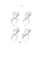
[0035] a figura 1 ilustra a invenção mostrando seis fases consecutivas de uma fixação de enxerto externo exemplificativa em um túnel ósseo com uso de uma modalidade exemplificativa do método de acordo com a invenção;[0035] figure 1 illustrates the invention showing six consecutive phases of an exemplary external graft fixation in a bone tunnel using an exemplary method of the method according to the invention;
[0036] a figura 2 mostra quatro fases consecutivas de uma cirurgia de substituição de ACL exemplificativa com uso do método mostrado na figura 1;[0036] figure 2 shows four consecutive phases of an exemplary ACL replacement surgery using the method shown in figure 1;
[0037] as figuras 3 e 4 ilustram duas aplicações exemplificativas adicionais de fixação de enxerto de acordo com a invenção, em um túnel ósseo que compreende uma porção de um diâmetro reduzido (figura 3) ou em um furo cego (figura 4);[0037] figures 3 and 4 illustrate two additional exemplary applications of graft fixation according to the invention, in a bone tunnel comprising a portion of a reduced diameter (figure 3) or in a blind hole (figure 4);
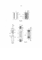
[0038] as figuras 5 a 9A/B mostram conjuntos exemplificativos adicionais que compreendem um prendedor, elemento de ancoragem e uma ferramenta de ancoragem, sendo que os conjuntos são adequados para o método de fixação de acordo com a invenção;[0038] figures 5 to 9A / B show additional exemplary sets comprising a fastener, anchoring element and an anchoring tool, the sets being suitable for the method of fixation according to the invention;
[0039] as figuras 10 a 17 são ilustrações tridimensionais ou seções axiais de modalidades exemplificativas adicionais de prendedor que são adequadas para métodos similares àqueles ilustrados nas figuras 1 e 5;[0039] figures 10 to 17 are three-dimensional illustrations or axial sections of additional exemplary fastener modalities that are suitable for methods similar to those illustrated in figures 1 and 5;
[0040] as figuras 18 a 22 são seções transversais através de enxertos que são fixados com o método de acordo com figuras 1,5,6 ou 7 em um túnel ósseo ou furo cego com o auxílio de modalidades exemplificativas adicionais de prendedor;[0040] figures 18 to 22 are cross-sections through grafts that are fixed with the method according to figures 1,5,6 or 7 in a bone tunnel or blind hole with the aid of additional exemplary fastener modalities;
[0041] a figura 23 mostra uma modalidade do método de acordo com a invenção que inclui uma etapa de pré-tratamento em que a parede da abertura é tratada com uma primeira porção de material que se liquefaz antes da introdução do prendedor;[0041] figure 23 shows an embodiment of the method according to the invention that includes a pre-treatment step in which the opening wall is treated with a first portion of material that liquefies before the fastener is introduced;
[0042] a figura 24 mostra uma modalidade do método de acordo com a invenção, em que um prendedor expansível é usado;[0042] figure 24 shows an embodiment of the method according to the invention, in which an expandable fastener is used;
[0043] a figura 25 ilustra uma modalidade exemplificativa adicional do método de acordo com a invenção, sendo que o método é adequado para a fixação de enxerto externo em um túnel ósseo ou em uma abertura cega;[0043] figure 25 illustrates an additional exemplary embodiment of the method according to the invention, the method being suitable for fixing an external graft in a bone tunnel or in a blind opening;
[0044] a figura 26 mostra uma modalidade exemplificativa adicional do método de acordo com a invenção, sendo que o método é adequado para uma fixação de enxerto externo em uma abertura cega;[0044] figure 26 shows an additional exemplary embodiment of the method according to the invention, the method being suitable for fixing an external graft in a blind opening;
[0045] as figuras 27 a 33 são seções transversais e representações tridimensionais de modalidades exemplificativas de prendedor adequadas para a fixação de enxerto interno com uso de um método similar àquele ilustrado nas figuras 1 ou 5;[0045] figures 27 to 33 are cross sections and three-dimensional representations of exemplary fastener modalities suitable for fixing an internal graft using a method similar to that illustrated in figures 1 or 5;
[0046] as figuras 34A/B mostram uma modalidade exemplificativa de um conjunto de acordo com a invenção, sendo que o conjunto compreende o prendedor, o elemento de ancoragem e a ferramenta de ancoragem e é adequado para uma fixação de enxerto interno com uso de um método similar àquele ilustrado nas figuras 6 ou 7;[0046] figures 34A / B show an exemplary embodiment of a set according to the invention, the set comprising the fastener, the anchoring element and the anchoring tool and is suitable for fixing an internal graft using a method similar to that illustrated in figures 6 or 7;
[0047] as figuras 35A/B mostram uma modalidade exemplificativa de um conjunto de acordo com a invenção, sendo que o conjunto compreende o prendedor, o elemento de ancoragem e a ferramenta de ancoragem e é adequado para uma fixação de enxerto interno com uso de um método similar àquele ilustrado na figura 25;[0047] figures 35A / B show an exemplary embodiment of a set according to the invention, the set comprising the fastener, the anchoring element and the anchoring tool and is suitable for fixing an internal graft using a method similar to that illustrated in figure 25;
[0048] a figura 36 mostra uma área de ocupação de uma fixação de um enxerto de dois filamentos de acordo com a invenção, cuja área de ocupação é particularmente adequada para a fixação de ACL tibial;[0048] figure 36 shows an area of occupation of a fixation of a graft of two filaments according to the invention, whose area of occupation is particularly suitable for fixation of tibial ACL;
[0049] as figuras 37, 38A/B e 39A/B/C mostra conjuntos de prendedor, elemento de ancoragem, ferramenta de ancoragem e ferramenta de guia, em que a ferramenta de guia é adequada não somente para guiar a ferramenta de ancoragem durante o processo de ancoragem, mas também para formar o prendedor para dentro da abertura ao longo de um fio-guia para estabelecer encaixe por pressão antes do processo de ancoragem ser iniciado.[0049] figures 37, 38A / B and 39A / B / C show fastener sets, anchor element, anchor tool and guide tool, in which the guide tool is suitable not only to guide the anchor tool during the anchoring process, but also to form the fastener into the opening along a guidewire to establish snap fit before the anchoring process is initiated.
[0050] Os itens que têm a mesma função e itens similares são denominados em todas as figuras com os mesmos numerais de referência.[0050] Items that have the same function and similar items are named in all figures with the same reference numerals.
[0051] A figura 1 mostra seis consecutivas (a) a (f) da fixação (fixação de enxerto externo) de um tecido mole em um túnel ósseo com uso de modalidades exemplificativas do método e prendedor de acordo com a invenção. O tecido mole é, por exemplo, um enxerto 1, que, conforme visto na fase (a), é posicionado para se estender através do túnel 2 e, se aplicável, é mantido com medidas conhecidas por si a uma tensão desejada durante o processo de fixação. No entanto, nem o método nem o prendedor precisam ser diferentes para prender um elemento protético ou um tecido mole natural no túnel, em que o enxerto ou tecido mole pode não se estender através do túnel, mas tem uma extremidade dentro do túnel e essa extremidade pode compreender um bloco ósseo terminal. Obviamente, no último caso a abertura pode ser também uma abertura cega, por exemplo, um furo cego. Além disso, o enxerto ou tecido mole pode compreender uma porção de extremidade suturada com extremidades de sutura que se estendem a partir da mesma, em que essa porção de extremidade é posicionada no túnel, sendo que as porções de extremidade de sutura saem através da segunda boca de túnel e são usadas, por exemplo, para tencionar o enxerto ou tecido mole (consulte também a figura 3).[0051] Figure 1 shows six consecutive (a) to (f) the fixation (fixation of external graft) of a soft tissue in a bone tunnel using exemplary modalities of the method and fastener according to the invention. The soft tissue is, for example, a graft 1, which, as seen in step (a), is positioned to extend through
[0052] O prendedor 3 é adaptado em seção transversal para ser capaz de encaixar por pressão o enxerto 1 no túnel 2. O prendedor 3 compreende uma cavidade interna 4, que é, por exemplo, substancialmente cilíndrica, que se estende a partir da face proximal do prendedor em direção à extremidade distal do prendedor, e que é conectada por uma passagem 5 ou uma pluralidade de passagens a um setor de ancoragem da superfície circunferencial do prendedor, isto é, a apenas um lado do prendedor 3. A passagem 5 pode ter a forma de um ou uma pluralidade de, por exemplo, fenestrações em formato de fenda, redondas ou poligonais ou de uma região de outra forma perfurada (por exemplo, material com uma porosidade aberta, por exemplo, metal trabecular ou sinterizado ou cerâmica). O elemento de ancoragem 6 é, por exemplo, um item em formato de pino de um material que tem propriedades termoplásticas, cujo material é adequado para ser liquefeito da maneira descrita acima, sendo que o elemento de ancoragem se encaixa na cavidade interna 4 para alcançar ao menos na região da passagem 5.[0052] The
[0053] O processo de fixação é preferencialmente executado conforme segue: O enxerto 1 posicionado através do túnel 2 conforme mostrado na (a) sofre impacto contra um lado da parede do túnel por introdução de um dilatador 10 entre o enxerto 1 e o lado oposto da parede do túnel conforme mostrado na fase (b), em que um dilatador afunilado em um lado 10 conforme ilustrado e usado com o lado afunilado voltado ao enxerto 1 se mostra mais eficaz. Esse impacto comprime o enxerto 1 ou, se aplicável, o bloco ósseo terminal do mesmo. Na fase (c), o dilatador 10 é removido e o prendedor 3 é forçado (força F.1) no espaço entre o enxerto 1 e a parede do túnel cujo espaço foi preparado na etapa de impacto. No mesmo, a passagem 5 do prendedor 3 se volta em direção à parede do túnel oposta ao enxerto 1 e o prendedor posicionado 3 é para encaixar por pressão o enxerto contra a parede do túnel. Para forçar o prendedor 5 no túnel, por exemplo, uma haste de pressão 11 que alcança a cavidade interna do prendedor 4 é usada. Ao invés de usar a haste de pressão 11 ilustrada para forçar o prendedor para dentro do túnel, uma ferramenta de êmbolo que atua na face proximal do prendedor face pode ser também usada. Na fase (d), a haste de pressão 11 é removida e um alargador 12 é introduzido na cavidade interna do prendedor 4, sua ponta distal angulada para alcançar a passagem 5. O alargador 12 é alternado para alargar a parede do túnel fora da passagem 5. Na fase (e), o alargador 12 é removido e o elemento de ancoragem 6 é introduzido na cavidade interna 4 e uma ferramenta de ancoragem 13 é colocada na face proximal do elemento de ancoragem 6 ou fixada ao mesmo. No mesmo, é vantajoso também posicionar uma ferramenta de guia 14, sendo que essa ferramenta de guia é equipara para guiar a ferramenta de ancoragem 13 e possivelmente o elemento de ancoragem 6 para ser capaz de ser avançado exatamente de modo coaxial na cavidade interna 4. A ferramenta de ancoragem 13 serve para produzir a ancoragem do prendedor através do elemento de ancoragem na parede do túnel, isto é, para transmitir ao elemento de ancoragem 6 energia, por exemplo, vibração ultrassónica, necessária para a liquefação do material que se liquefaz e uma força F.2 para avançar o elemento de ancoragem 6 em direção à extremidade distal do prendedor, de forma que o material do elemento de ancoragem 6 seja liquefeito e, em um estado líquido, seja feito fluir através da passagem 5 no tecido ósseo da parede do túnel, onde em ressolidificação este constitui uma ancoragem 15 do prendedor 3 no tecido ósseo conforme mostrado na fase (f).[0053] The fixation process is preferably performed as follows: Graft 1 positioned through
[0054] Obviamente, no método conforme ilustrado na figura 1, o estabelecimento do encaixe por pressão (fase (c)) e o estabelecimento da ancoragem (fase (e)) são executados um após o outro e independentemente entre si, em que a força F.2, que é aplicada ao elemento de ancoragem para o avanço do mesmo na etapa de ancoragem (fase (e)) é neutralizada pelo prendedor 3 e tem a mesma direção que a força F.1 que é necessária para estabelecer o encaixe por pressão (fase (c)), isto é, não tem componente em uma força de direção oposta F.1 e, sendo assim, não pode de qualquer forma enfraquecer o encaixe por pressão do enxerto ou tecido mole através do prendedor.[0054] Obviously, in the method as illustrated in figure 1, the establishment of the pressure fitting (phase (c)) and the establishment of the anchoring (phase (e)) are performed one after the other and independently of each other, in which the force F.2, which is applied to the anchoring element to advance it in the anchoring step (phase (e)) is neutralized by
[0055] Dependendo da seção transversal do enxerto 1 em um estado não impactado, a etapa de impacto (fase (b)) pode ser omitida. O uso de um prendedor afunilado ou extremidade distai de prendedor afunilado pode também tornar a etapa de impacto desnecessária. Dependendo da densidade do tecido ósseo da parede do túnel e da resistência desejada da ancoragem, a etapa de alargamento (fase (d)) pode ser omitida. O alargamento é aconselhável para tecido ósseo muito denso. Se a etapa de alargamento for executada, a ancoragem atingida na etapa (e) será mais profunda e atingira o tecido ósseo que não foi compactado pelo encaixe por pressão. No entanto, um efeito similar pode ser atingido equipando-se o prendedor com um sulco axial que se estende da extremidade distai à boca externa da passagem 5. A ferramenta de guia 14 pode ser posicionada na extremidade proximal do prendedor 3 antes da etapa de alargamento ou até mesmo antes do estabelecimento do encaixe por pressão, em que no último caso, a ferramenta de guia é usada para forçar o prendedor 3 na abertura ao invés da haste de pressão 11. Dependendo do curso de avanço do elemento de ancoragem necessário para atingir a ancoragem desejada (fase (e)) e da guiabilidade da ferramenta de ancoragem 13, o uso de uma ferramenta de guia 14 pode ser omitido.[0055] Depending on the cross section of the graft 1 in an non-impacted state, the impact step (phase (b)) can be omitted. The use of a tapered fastener or distal end of a tapered fastener can also make the impact step unnecessary. Depending on the density of the bone tissue in the tunnel wall and the desired anchorage strength, the enlargement step (phase (d)) can be omitted. Enlargement is advisable for very dense bone tissue. If the widening step is performed, the anchoring achieved in step (e) will be deeper and will reach the bone tissue that was not compacted by the pressure fitting. However, a similar effect can be achieved by equipping the fastener with an axial groove that extends from the distal end to the outer mouth of the passage 5. The
[0056] Pode ser vantajoso usar um fio-guia para introduzir o dilatador 10 e/ou o prendedor 3 na abertura do osso que necessita de uma maneira por si mesma de um canal ou furo axial (central ou excêntrico) no dilatador 10 e/ou no prendedor 3. Os experimentos mostram que é vantajoso fornecer o furo axial no dilatador 10 e/ou no prendedor 3 o mais próximo possível da superfície circunferencial do lado que deve se voltar em direção à parede da abertura. Ao invés do furo, é possível fornecer um sulco (preferencialmente um corte inferior) ao longo da superfície circunferencial do dilatador e/ou do prendedor para guiar os mesmos ao longo do fio-guia.[0056] It may be advantageous to use a guidewire to introduce the dilator 10 and / or the
[0057] A figura 1 mostra o prendedor introduzido na abertura do osso 2 com sua face proximal sendo nivelado com a superfície do osso. Essa, é claro, não é uma condição do método de acordo com a invenção. Sem alteração ao prendedor e ao método, é possível também introduzir o prendedor ainda mais no osso, de forma que a extremidade proximal do prendedor seja enterrada no osso, ou menos distante, de forma que a extremidade proximal do prendedor se projete a partir do osso.[0057] Figure 1 shows the fastener inserted in the opening of
[0058] Conforme já mencionado, a ferramenta de ancoragem 13 é, por exemplo, uma ferramenta de vibração (por exemplo, sonotrodo conectado a um transdutor ultrassónico que é, por exemplo, parte de um dispositivo ultrassónico tal como uma peça de mão ultrassónica), que transmite vibração ultrassónica ao elemento de ancoragem 6 e é simultaneamente pressionada contra a face proximal do mesmo ou é rigidamente fixada ao mesmo e pressionada contra a extremidade distai fechada do prendedor 3 juntamente com o elemento de ancoragem. Em tal caso, é vantajoso fornecer ou no elemento de ancoragem 6 ou dentro da cavidade interna 4 direcionadores de energia (pontos ou bordas protuberantes) em que a liquefação é desejada. Tal direcionador de energia para o prendedor 3 e para o elemento de ancoragem 6 no caso ilustrado é constituído pela extremidade distai afunilada do elemento de ancoragem 6. As modalidades alternativas de tais direcionadores de energia são, por exemplo, bordas ou pontos que se projetam na cavidade interna a partir da margem da boca interna da passagem 5. As modalidades adicionais de tais direcionadores de energia são reveladas no pedido provisório n° US 61/259383 (ainda não publicada), cuja descrição é incorporada ao presente em sua totalidade a título de referência.[0058] As already mentioned, the anchoring
[0059] A ferramenta de ancoragem 13 pode ser também equipada para transmitir a energia rotacional ao elemento de ancoragem que é rigidamente fixado ao mesmo, em que o calor necessário para a liquefação do elemento de ancoragem material é em tão caso produzido por atrito entre a face distal do elemento giratório de ancoragem e a superfície interna não giratória do prendedor. Alternativamente, a ferramenta de ancoragem 13 pode ser equipara para transferir energia eletromagnética (preferencialmente na faixa de frequência visível ou infravermelha) ou energia elétrica ao elemento de ancoragem 6 ou ao prendedor 3, em que ou o elemento de ancoragem 6 ou as regiões do prendedor na proximidade do elemento de ancoragem precisam ser equipados para transformar a energia transmitida em energia térmica, por exemplo, compreendendo meios de absorção de luz ou meios de resistência elétrica.[0059] The
[0060] Se o prendedor 3 de acordo com figura 1 for usado para fixação de enxerto externo em uma abertura cega, pode ser desejável ancorar o mesmo adicionalmente à ancoragem na parede circunferencial da abertura também na parede de fundo da abertura ou exclusivamente na parede de fundo da abertura (consulte também a figura 26). Em tal caso, o prendedor precisa ser introduzido no furo cego de forma que o mesmo substancialmente toque ou ao menos chegue perto da parede de fundo da abertura e precisa compreender ao menos uma passagem 5 que conecta a cavidade interna do prendedor 4 com uma face distal do prendedor, cuja passagem é fornecida adicionalmente ou em lugar da passagem lateral 5 ilustrada na figura 1. Sendo que tal superfície distal do prendedor é equipara para o prendedor ancoragem constituir uma porção de superfície de prendedor que é separada das porções de superfície de prendedor equipadas para pressionar não como um setor circunferencial (conforme descrito acima para a superfície que compreende a passagem lateral 5), mas como uma porção axial, conforme já mencionado mais acima.[0060] If
[0061] O prendedor 3 é feito de um material que pode ou não ser biologicamente reabsorvível conforme conhecido para prendedores de acordo com o estado da técnica, que servem para os mesmos fins. Se o prendedor não for reabsorvível, esse é, por exemplo, feito de um metal (por exemplo, titânio, liga de titânio, aço inoxidável), um material de cerâmica (por exemplo, óxido de alumínio, óxido de zircônio), um fosfato de cálcio ou de um polímero (por exemplo, termoplástico, por exemplo, PEEK, possivelmente revestido, por exemplo, com um revestimento interno de titânio e um revestimento externo de hidroxiapatita). Embora pareça vantajoso produzir o prendedor de um material que não seja que se liquefaz sob as condições do processo de ancoragem, os experimentos mostram que o prendedor pode ser também feito de um material que se liquefaz, até do mesmo material como o material que se liquefaz do elemento de ancoragem. Bons resultados foram, por exemplo, atingidos com prendedores feitos de titânio, ou de ácido polilático (PLA) preenchido com Hidroxiapatita ou fosfatos de cálcio, particularmente de PLLA preenchido com 60% de fosfato de tricálcio ou PDLLA a 70%/30% (70%L e 30%D/L) preenchido com 30% de fosfato de cálcio bifásico, combinado com elementos de ancoragem de PLDLLA 70%/30% (70%L e 30% D/L), conforme disponível junto à Bõhringer como LR706.[0061]
[0062] Particularmente, em um caso em que o enxerto (ou natural tecido mole ou elemento artificial correspondente) a ser preso é muito sensível ao calor é preferível para uso, ao menos para uma região de prendedor que deve estar situada na proximidade do enxerto, um material que tem algumas características de isolamento de calor. Se o enxerto a ser preso for menos sensível ao calor (por exemplo, material de substituição de tecido artificial), tal precaução não é necessária. Para tal tecido não sensível ao calor que adicionalmente é suficientemente deformável é até possível fornecer passagens 5 direcionadas também ao lado do enxerto, em que para o processo de ancoragem essas passagens serão fechadas pelo enxerto compactado e não permitirá ou dificilmente permitirá a passagem do material liquefeito (vantagem: nenhuma orientação de prendedor giratório específica na abertura é necessária).[0062] Particularly, in a case where the graft (or natural soft tissue or corresponding artificial element) to be attached is very sensitive to heat it is preferable for use, at least for a fastener region that must be located in the vicinity of the graft , a material that has some heat insulation characteristics. If the graft to be attached is less sensitive to heat (for example, artificial tissue replacement material), such a precaution is not necessary. For such non-heat-sensitive fabric that is additionally sufficiently deformable, it is even possible to provide passages 5 also directed to the side of the graft, in which for the anchoring process these passages will be closed by the compacted graft and will not allow or will hardly allow the passage of the liquefied material. (advantage: no specific swivel fastener orientation at the opening is required).
[0063] A fixação de enxerto externo conforme ilustrada na figura 1 pode ser, por exemplo, atingida por fornecimento de um túnel ou furo cego de 8 mm de diâmetro, um prendedor substancialmente cilíndrico de 7 mm de diâmetro e um enxerto que tem uma porção de extremidade suturada que passa facilmente através de um furo de 7 mm de diâmetro. Os experimentos mostram que os prendedores substancialmente cilíndricos com uma extremidade distai afunilada, particularmente com uma extremidade hemisférica conforme ilustrada na figura 1 e com uma superfície circunferencial de uma aspereza de não mais que 10 pm de profundidade geram um bom encaixe por pressão e podem ser introduzidos com forças razoáveis, enquanto os prendedores com extremidades distais planas e/ou uma aspereza de superfície maior parecem necessitar de forças de introdução maiores, mas não resultam em um encaixe por pressão maior. Um encaixe por pressão mais forte é atingido com uso de prendedores mais longos.[0063] External graft fixation as illustrated in figure 1 can, for example, be achieved by providing a tunnel or blind hole 8 mm in diameter, a substantially cylindrical fastener 7 mm in diameter and a graft that has a portion sutured end that easily passes through a 7 mm diameter hole. The experiments show that the substantially cylindrical fasteners with a tapered distal end, particularly with a hemispherical end as shown in Figure 1 and with a circumferential surface of a roughness of no more than 10 pm in depth, generate a good pressure fit and can be inserted with reasonable forces, while fasteners with flat distal ends and / or greater surface roughness appear to require greater introducing forces, but do not result in a greater pressure fit. A stronger pressure fit is achieved with the use of longer fasteners.
[0064] A figura 2 mostra de uma maneira esquemática quatro fases consecutivas (a) a (d) de um procedimento cirúrgico exemplificative para substituir um ligamento cruzado anterior (ACL) em um joelho humano, em que o enxerto 1 usado para a substituição compreende, por exemplo, dois blocos ósseos terminais e em que um desses blocos ósseos terminais é preso em um furo cego 20 no osso femoral 21 e o outro em um túnel 22 que alcança através do osso tibial 23. O procedimento conhecido por si mesmo compreende um processo de fixação femoral e tibial que podem ser ambos executados com uso do método de acordo com a invenção conforme, por exemplo, ilustrado na figura 1.[0064] Figure 2 shows schematically four consecutive phases (a) to (d) of an exemplary surgical procedure to replace an anterior cruciate ligament (ACL) in a human knee, in which the graft 1 used for the replacement comprises , for example, two terminal bone blocks and in which one of these terminal bone blocks is stuck in a
[0065] Na fase (a), o túnel tibial 22 e o furo cego femoral 20 são fornecidos e o enxerto 1 é posicionado para os processos de fixação. Na fase (b), o prendedor femoral 3.1 é encaixado por pressão no furo cego femoral 20. Na fase (c), o prendedor femoral 3.1 é ancorado na parede do furo cego femoral 20 (ancoragem 15.1). Na fase (d), o prendedor tibial 3.2 é encaixado por pressão e ancorado (ancoragem 15.2) no túnel tibial 22.[0065] In phase (a), the
[0066] A figura 3 mostra, conforme mencionado mais acima, a fixação de uma extremidade de enxerto suturada 16 na abertura do osso 2 com uso de um método de fixação similar àquele ilustrado na figura 1. A abertura do osso 2 é um túnel e compreende uma porção 2.1 de uma seção transversal maior e uma porção 2.2 de uma seção transversal menor, em que a extremidade de enxerto suturada 16 e o prendedor 3 são dispostos na porção de túnel 2.1 e as extremidades de sutura 17 que se estendem da extremidade de enxerto suturada 16 saem através da porção de túnel 2.2 e são, por exemplo, suadas para tencionar o enxerto antes de comprimir o mesmo com o dilatador ou introduzir o prendedor 3. O enxerto 1 que compreende a extremidade de enxerto suturada 16 é, por exemplo, um enxerto de dois filamentos em que os dois filamentos são fixados entre si por uma série de costuras transversais ao redor de ambos os lados laterais e feitos com uma, sendo que as duas extremidades de sutura 17 se projetam a partir da extremidade de enxerto suturada. O enxerto 1 pode também ser um enxerto de quatro filamentos que é produzido dobrando em dois um enxerto de dois filamentos com as duas extremidades sendo suturadas da maneira mencionada, sendo que o enxerto de quatro filamentos então compreende uma extremidade dobrada com extremidades de sutura e uma extremidade suturada com quatro extremidades de sutura se projetando. A etapa de ancoragem do prendedor na parede da porção de túnel 2.1 é, por exemplo, executada conforme descrito acima em conexão com a figura 1.[0066] Figure 3 shows, as mentioned above, the fixation of a sutured graft end 16 in the opening of
[0067] A figura 4 mostra a fixação de uma extremidade de enxerto suturada 16 em uma abertura do osso 2 que é a furo cego, em que a extremidade de enxerto suturada 16 é fixada ao prendedor 3 preferencialmente com o auxílio das extremidades de sutura 17 que se projetam a partir da extremidade de enxerto suturada 16. Essa fixação é estabelecida antes da introdução da extremidade do enxerto 16 e o prendedor 3 na abertura e as duas são introduzidas juntas na abertura 2 para estabelecer o encaixe por pressão. A figura 3 mostra a extremidade do enxerto 16 e o prendedor 3 posicionados na abertura do osso 2. A etapa de ancoragem do prendedor 3 na parede da abertura é estabelecida, por exemplo, da maneira conforme ilustrada na figura 1.[0067] Figure 4 shows the fixation of a sutured graft end 16 in an opening of the
[0068] A fixação de uma extremidade de enxerto suturada ao prendedor 3 pode ser, por exemplo, atingida, conforme ilustrado na figura 4, por costura de uma primeira parte da extremidade de sutura 17 através da cavidade interna 4 do prendedor 3, que para esse fim compreende uma extremidade distai aberta e uma segunda parte das extremidades de sutura 17 ao longo da superfície circunferencial do prendedor 3 e fornece um nó ou outro retentor de sutura adequado na face proximal do prendedor para conectar as duas partes das extremidades de sutura 17. A superfície circunferencial do prendedor e/ou a cavidade interna do prendedor pode compreender um sulco que se estende axialmente para acomodação das extremidades de sutura. Se a sutura for aquecida ao calor e houver um risco da sutura ser danificada pelo material liquefeito dentro da cavidade interna do prendedor, será vantajoso fornecer ao menos um túnel separado através do prendedor para a sutura (consulte também a figura 19). É também possível equipar a extremidade distal do prendedor 3 com um orifício ou meio de retenção similar ao qual a extremidades de sutura 17 que se projeta a partir da extremidade de enxerto suturada 16 pode ser fixada de uma maneira adequada antes da extremidade do enxerto 16 e o prendedor 3 são introduzidos na abertura do osso 2 juntamente. É também obviamente possível fixar uma extremidade de enxerto não suturada ao prendedor de uma maneira adequada.[0068] The fixation of a sutured graft end to the
[0069] As figuras 5 a 9A/B mostram modalidades exemplificativas adicionais de prendedores 3 juntamente com elementos de ancoragem 6 e ferramentas de ancoragem 13 adaptados, em que todos os conjuntos ilustrados de prendedor 3, elemento de ancoragem 6 e ferramenta de ancoragem 13 são adequados para uma etapa de ancoragem que é ligeiramente diferente da etapa de ancoragem ilustrada na figura 1, mas que são todos adequados para as aplicações de fixação conforme ilustradas nas figuras 1 a 4. As figuras 5 a 9 ilustram as etapas de ancoragem para a fixação de enxerto externo, mas conforme discutido mais abaixo, o princípio é aplicável para fixação de enxerto interno também.[0069] Figures 5 to 9A / B show additional exemplary types of
[0070] A figura 5 mostra uma seção axial de um prendedor 3 que é encaixado por pressão em um túnel ósseo 2 para prender um enxerto 1 no túnel ósseo. O prendedor 3 é principalmente o mesmo que o prendedor ilustrado na figura 1, mas conforme a passagem 5 que alcança a partir da cavidade interna 4 até a superfície externa do prendedor, uma pluralidade de aberturas é fornecida ao invés da fenestração do tipo uma fenda de acordo com a figura 1. O elemento de ancoragem 6 é no formato de tubo e repousa de forma frouxa na peça de pé 25 de uma extensão 26 da ferramenta de ancoragem 13, que novamente é preferencialmente uma ferramenta de vibração. Para o processo de ancoragem, a extensão 26 juntamente com o elemento de ancoragem 6 é introduzida na cavidade interna 4 do prendedor 3. A ferramenta de ancoragem 13 é então ativada e o elemento de ancoragem 6 é retido e avançado contra a peça de pé 25 por aplicação de uma força correspondente F.2 a um contra elemento 27 que atua na face proximal do elemento de ancoragem 6. O material termoplástico compreendido pelo elemento de ancoragem 6 é liquefeito na face distai do elemento de ancoragem 6 em que esse está em contato com a peça de pé da ferramenta de vibração 25. Pelo posicionamento correspondente da interface entre a peça de pé 25 e o elemento de ancoragem 6 o material liquefeito é feito fluir através da passagem 5 na parede do túnel, em que essa interface é deslocada para processos de ancoragem subsequentes através de diferentes passagens 5. A figura 5 mostra a configuração durante o processo de ancoragem, em que o material de ancoragem já foi forçado através de uma passagem distai e média 5, em que a interface mencionada é posicionada na passagem média e em que uma passagem proximal está ainda livre do material de ancoragem.[0070] Figure 5 shows an axial section of a
[0071] Com a combinação de elemento de ancoragem 6, ferramenta de ancoragem 13 e contra elemento 27 conforme mostrado na figura 5, o avanço do elemento de ancoragem 6 pode também ser efetuado por atração da peça de pé 25 em direção à face proximal do prendedor 3, enquanto mantém o contra elemento 27 substancialmente estacionário, por exemplo, pressionado contra a superfície óssea. É também possível reverter as funções da ferramenta de ancoragem e contra ferramenta, isto é, para vibrar o contra elemento 27 e usar a peça de pé 25 como um contra elemento. Além disso, para a ancoragem do prendedor conforme ilustrada na figura 5, conforme já mencionado para a ancoragem do prendedor de acordo com a figura 1, é também possível usar outros tipos de energia que a energia de vibração. Modalidades adicionais e detalhes do princípio do processo de ancoragem conforme ilustrado na figura 5 são descritos na publicação WO-2009/132472, cuja descrição é incorporada ao presente em sua totalidade a título de referência. Em uma modalidade alternativa da combinação de elemento de ancoragem 6 e ferramenta de ancoragem 13, conforme ilustrada na figura 5, o elemento de ancoragem em formato de tubo 6 constitui o elemento consumível em um dispositivo do tipo dispensador e é liquefeito em uma extremidade distal do dispositivo de uma forma similar conforme mostrado na figura 5. Tais dispositivos dispensadores são descritos na publicação WO-2010/127462 cuja descrição é incorporada ao presente em sua totalidade a título de referência.[0071] With the combination of
[0072] É óbvio que no método de fixação conforme ilustrado pela figura 5 a força F.2 necessária para avançar o elemento de ancoragem 6 não é neutralizada pelo prendedor 3. Sendo assim, essa força não pode enfraquecer o encaixe por pressão do prendedor, seja qual for sua direção e isso permite o uso de um prendedor que não tem uma extremidade distai fechada e a introdução do elemento de ancoragem a partir ou da extremidade proximal ou distal do prendedor.[0072] It is obvious that in the fastening method as shown in figure 5, the F.2 force necessary to advance the
[0073] A figura 6 é uma seção axial de um conjunto adicional de prendedor 3, elemento de ancoragem 6 e ferramenta de ancoragem 13, em que o prendedor 3 é mostrado na abertura do osso 2 antes da etapa de ancoragem, isto é, encaixado por pressão entre o enxerto 1 e a parede oposta da abertura do osso 2. Exceto o descrito acima, o prendedor 3 não compreende uma cavidade interna e passagens que conectam a cavidade interna à superfície externa do prendedor (conforme ilustrado nas figuras 1 a 5), mas, ao invés disso, para guiar o material que se liquefaz comprimido pelo elemento de ancoragem 6 de uma face proximal do prendedor face para as porções de ancoragem da superfície circunferencial do prendedor, o prendedor 3 compreende ao menos um sulco 30 que se estende a partir da face proximal do prendedor em direção à extremidade distal do prendedor e pode ter uma seção transversal ligeiramente reduzida. O elemento de ancoragem 6 é adaptado para substancialmente preencher essa seção transversal e se projetar ligeiramente a partir dessa e é pressionado para o sulco 30 do prendedor encaixado por pressão 3 a partir da face proximal do prendedor com o auxílio da ferramenta de ancoragem 13. No mesmo, o elemento de ancoragem 6 é vantajosamente acoplado de modo rígido à extremidade distal da ferramenta de ancoragem 13, de forma que a energia de vibração (ou outro tipo de energia) seja transmitida substancialmente livre de perda para o elemento de ancoragem e a liquefação ocorre onde o elemento de ancoragem entra em contato com o tecido ósseo da parede da abertura do osso e possivelmente também onde o elemento de ancoragem entra em contato com a superfície interna do sulco 30. O sulco 30 pode compreender uma superfície interna áspera ou de outra forma adequadamente estruturada de forma que a liquefação e ressolidificação do material de ancoragem podem resultar em uma conexão de encaixe positivo não somente com o tecido ósseo da parede do osso, mas ao mesmo tempo também com o sulco dentro da superfície do prendedor 30.[0073] Figure 6 is an axial section of an additional set of
[0074] Se um prendedor 3 de acordo com figura 6 compreender mais de um sulco, a ancoragem do prendedor necessita de mais de uma etapa de ancoragem, em que essas etapas de ancoragem podem ser executadas em sucessão com uso de uma e a mesma ferramenta de ancoragem para todas as etapas, ou em que as etapas de ancoragem podem ser executadas simultaneamente com uso de uma ferramenta de ancoragem em formato de garfo.[0074] If a
[0075] A figura 7 é uma seção axial através de uma modalidade adicional de um conjunto de prendedor 3, elemento de ancoragem 6 e ferramenta de ancoragem 13, cujo conjunto compreende ainda uma ferramenta de guia 14 e é adequado para um processo de ancoragem similar àquele descrito em conexão com a figura 6. O conjunto é ilustrado com o prendedor 3 encaixado por pressão juntamente com um enxerto 1 em uma abertura do osso 2, sendo que o conjunto está pronto para a etapa de ancoragem. A ferramenta de guia 14 compreende um furo de passagem axial que tem uma seção transversal adaptada à seção transversal do elemento de ancoragem 6 e à extremidade distai da ferramenta de ancoragem 13, em que o furo de passagem é angulado em relação a um eixo geométrico da ferramenta em um ângulo agudo de 2 a 10°, preferencialmente 3o. Conforme já ilustrado na figura 6, para a etapa de ancoragem, o elemento de ancoragem 6 deve ser avançado a partir da face proximal do prendedor ao longo de um sulco 30 fornecido no lado do prendedor oposto ao enxerto 1. Exceto o mostrado na figura 6, o sulco 30 de acordo com a figura 7 compreende uma porção de entrada mais ampla 30.1 e uma porção distai mais estreita 30.2, em que a porção distai preferencialmente tem uma extremidade fechada. Na preparação da etapa de ancoragem, a ferramenta de guia 31, que pode também servir para forçar o prendedor na abertura do osso 2, é posicionada na face proximal do prendedor com a boca distai de seu furo de passagem estando alinhada com a porção de entrada do sulco 30. O elemento de ancoragem 6 e a extremidade distal da ferramenta de ancoragem 13 estão posicionados no furo de passagem da ferramenta de guia 31, sendo eu a extremidade distal do elemento de ancoragem é suportada na porção de entrada 30.1 do sulco 30. Durante o processo de ancoragem, o elemento de ancoragem 6 é avançado no sulco 30, em que a posição angulada do elemento de ancoragem 6, conforme ilustrada na figura 7, em comparação com a posição axial, conforme mostrada na figura 6, força o material do elemento de ancoragem mais contra a parede da abertura do osso e com isso acentua a liquefação e penetração no tecido ósseo. Esse efeito é ampliado pelo sulco 30 que tem uma extremidade fechada.[0075] Figure 7 is an axial section through an additional embodiment of a fastener set 3,
[0076] Os experimentos mostram que a ancoragem de um prendedor que tem um diâmetro de 8 mm e uma porção distal do sulco 30.2 de uma seção transversal semicircular de 1,5 a 2 mm de rádio com uso de um elemento de ancoragem em formato de pino de 3,5 mm de diâmetro gera bons resultados.[0076] The experiments show that the anchoring of a fastener that has a diameter of 8 mm and a distal portion of the groove 30.2 of a semicircular cross section of 1.5 to 2 mm radius with the use of an anchor element in the shape of 3.5 mm diameter pin generates good results.
[0077] A figura 8 é uma seção axial através de uma modalidade adicional de um conjunto de prendedor 3, elemento de ancoragem 6, e ferramenta de ancoragem 13, sendo que o prendedor 3 e um enxerto 1 são mostrados encaixados por pressão em um túnel ósseo antes da etapa de ancoragem. O elemento de ancoragem 6 é constituído por uma parte central integrada do prendedor 3 que é, por exemplo, completamente feito do material que se liquefaz, em que esse material pode compreender compostos de carga (lâminas, fibras, partículas) cuja concentração pode diminuir em uma direção a partir da superfície circunferencial do prendedor em direção à região central do prendedor que constitui o elemento de ancoragem 6. O prendedor compreende uma cavidade interna 4 na forma de um canal axial e ao menos uma passagem 5 que conecta o canal com um setor de ancoragem da superfície circunferencial do prendedor. O canal preferencialmente tem uma porção proximal mais ampla 32 e uma porção distai mais estreita 33, e a ferramenta de ancoragem 13 adaptada ao prendedor 3 tem ao menos uma porção distai que é adaptada à porção mais ampla do canal 32 para ser guiada no mesmo. O elemento de ancoragem 6 é constituído pela porção de prendedor que cerca a porção distai (mais estreita) do canal 33 e é avançada e liquefeita forçando-se a ferramenta de ancoragem 13 da porção mais ampla do canal 32 para a porção mais estreita do canal assim pressionando o material liquefeito através das passagens 5 para a superfície externa do prendedor. Modalidades adicionais e detalhes do prendedor e processo de ancoragem conforme ilustrados na figura 8 são descritos na publicação US-2008/262517 (Stryker Trauma GmbH), cuja descrição é incorporada ao presente em sua totalidade a título de referência.[0077] Figure 8 is an axial section through an additional modality of a fastener set 3, anchoring
[0078] A figura 9A é uma seção axial através de uma modalidade adicional de um conjunto que compreende um prendedor 3, um elemento de ancoragem 6 e uma ferramenta de ancoragem 13, em que o prendedor 3 é mostrado encaixado por pressão a um enxerto 1 em uma abertura do osso 2, no lado esquerdo da figura antes da etapa de ancoragem e no lado direito da figura após a etapa de ancoragem. A modalidade pode ser considerada como sendo uma combinação da modalidade de acordo com as figuras 6 e 8, isto é, compreende ao menos um elemento de ancoragem 6 integrado no prendedor 3 que pode consistir completamente no material de ancoragem, e que possivelmente contém uma carga que tem possivelmente uma concentração menor em que o material deve ser liquefeito então em outras áreas, conforme discutido em conexão com a figura 8. No entanto, exceto o mostrado na figura 8, o elemento de ancoragem 6 ou o material a ser liquefeito respectivamente não está situado em uma área central do prendedor, mas na superfície circunferencial do mesmo, conforme discutido em conexão com a figura 6. A ferramenta de ancoragem 13, que preferencialmente tem uma extremidade distai afunilada, é forçada no material do prendedor material paralelo à parede da abertura do osso na região de superfície do material que se liquefaz. Quando após a conclusão da etapa de ancoragem a ferramenta de ancoragem é removida, essa deixa um vão 15’ entre uma área central do prendedor e a ancoragem 15 na parede do osso, que é conectada ao resto do prendedor junto ao vão 15’ conforme claramente visto na figura 9B (seção transversal através do prendedor ancorado 3).[0078] Figure 9A is an axial section through an additional modality of a set comprising a
[0079] As figuras 10 a 17 mostram várias modalidades de prendedores 3 com base no princípio do prendedor (prendedor com cavidade interna 4 conectada à superfície circunferencial do prendedor e o elemento de ancoragem adaptado para se encaixar na cavidade interna do prendedor) conforme ilustrado nas figuras 1 a 5, mas diferindo na forma. Todos esses prendedores 3 são aplicáveis nos métodos e aplicações de fixação conforme ilustrado nas figuras 1 a 5.[0079] Figures 10 to 17 show various types of
[0080] A figura 10 é uma ilustração tridimensional de um prendedor muito simples 3 que tem a forma de um cilindro circular com uma extremidade distai redonda. Esse compreende uma cavidade interna 4 e somente uma passagem em formato de fenda 5 que conecta a cavidade interna 4 com a superfície circunferencial do prendedor.[0080] Figure 10 is a three-dimensional illustration of a very
[0081] As figuras 11 a 13 são ilustrações tridimensionais de prendedores adicionais 3 similares ao prendedor da figura 10. Esses prendedores compreendem no lado direito (setor de ancoragem da superfície circunferencial do prendedor) as passagens 5 que conectam a superfície circunferencial do prendedor com a cavidade interna 4. As passagens são nas figuras 11 e 13 duas fileiras de furos que se estendem axialmente (uma fileira visível), na figura 12 uma fileira que se estende axialmente de fendas que se estendem de modo substancialmente circunferencial. Os prendedores das figuras 11 a 13 compreendem ainda no lado esquerdo (setor de pressionamento 34 da superfície circunferencial do prendedor) um setor achatado ou côncavo que forma um sulco raso para acomodar o enxerto a ser preso. Adicionalmente, o prendedor da figura 13 compreende uma crista que se estende axialmente 35 no centro do setor de pressionamento 34 cuja crista serve para reter um enxerto dobrado (não mostrado) que é dobrado sobre a extremidade distai da crista 35 para ser forçado na abertura do osso juntamente com o prendedor 3 de uma forma similar àquela discutida em conexão com a figura 4.[0081] Figures 11 to 13 are three-dimensional illustrations of
[0082] A figura 14 é uma seção axial de um prendedor adicional 3, sendo que o prendedor é ilustrado pressionado por pressão com um enxerto 1 em uma abertura do osso e a figura ilustra ainda o elemento de ancoragem 6, a ferramenta de ancoragem 13 e uma ferramenta de guia 14 similar à ferramenta de guia conforme discutida em conexão com a figura 7, sendo que todo o conjunto está pronto para a etapa de ancoragem. O prendedor 3 compreende ao menos um canal 4/5 (combinação da cavidade interna 4 e passagem 5) que se estende a um ângulo com relação ao eixo geométrico do prendedor. O ao menos um canal 4/5 compreende uma primeira boca na face proximal do prendedor que serve para introdução do elemento de ancoragem 6 e possivelmente uma extremidade distai da ferramenta de ancoragem e uma segunda boca na superfície circunferencial do prendedor, que serve para pressionar o material de ancoragem contra a parede do osso da abertura do osso, em que o material de ancoragem ou é liquefeito dentro do canal 4/5, que para esse fim preferencialmente compreende direcionadores internos de energia, ou na interface com a parede do osso.[0082] Figure 14 is an axial section of an
[0083] A figura 15 é uma seção axial de uma modalidade adicional de prendedor que compreende uma cavidade interna 4 e uma passagem 5 em que a cavidade interna 4 é disposta não coaxial com o eixo geométrico do prendedor e compreende uma etapa 4’ ou uma curva correspondente que é capaz de desviar o elemento de ancoragem 6 em direção à passagem 5. Essa disposição resulta em um efeito de forçar o material de ancoragem em direção à superfície do prendedor ou a parede do osso respectivamente de uma maneira similar conforme discutido em conexão com a figura 7.[0083] Figure 15 is an axial section of an additional fastener modality comprising an
[0084] A figura 16 é uma vista lateral de um prendedor adicional 3 que compreende uma cavidade interna 4 e as passagens 5 que conectam a cavidade interna com a superfície circunferencial do prendedor. O prendedor compreende as regiões de extremidade distai e proximal que têm uma seção transversal maior que uma região média. As duas regiões de extremidade são particularmente esféricas. Os experimentos mostram que o prendedor de acordo com a figura 16 fornece um encaixe por pressão tão bom quanto um prendedor cilíndrico, mas pode ser introduzido na abertura do osso com menos força.[0084] Figure 16 is a side view of an
[0085] A figura 17 é uma ilustração tridimensional de uma extremidade distal de um prendedor 3, que é vantajosa por ser introduzida na abertura do osso junto a um enxerto, em que o enxerto é posicionado no lado do prendedor 3 que está na figura 17 no lado esquerdo do prendedor. A extremidade distal do prendedor é afunilada nesse lado do enxerto para impedir que o enxerto se danifique na introdução do prendedor junto ao enxerto na abertura do osso. A extremidade distal do prendedor é afunilada no lado de não enxerto (lado direito na figura 17) também, mas menos, em que a boca distal de um furo de passagem axial através do prendedor para acomodação de um fio-guia está situada no mesmo. Conforme já mencionado em conexão com a figura 1, é vantajoso posicionai o furo de passagem 37 e com o mesmo o fio-guia de modo excêntrico e o mais próximo possível ao lado de ancoragem do prendedor. O furo de passagem 37 ou uma seção proximal do mesmo pode ou não servir como a cavidade interna 4 conforme descrito para as modalidades do prendedor de acordo com, por exemplo, as figuras 1 ou 5.[0085] Figure 17 is a three-dimensional illustration of a distal end of a
[0086] As figuras 18 a 22 ilustram formas em que em uma fixação de acordo com a invenção o prendedor 3 pode ser adaptado ao enxerto 1 e à abertura do osso 2. Os prendedores ilustrados são todos adequados para a fixação de enxerto externo e são parcialmente baseados no princípio do prendedor conforme ilustrado nas figuras 1 a 5 (prendedor com cavidade interna e ao menos uma passagem que conecta a cavidade à superfície circunferencial do prendedor e elemento de ancoragem adaptado para ser posicionado na cavidade interna), e parcialmente no princípio de prendedor conforme ilustrado nas figuras 6 e 7 (prendedor com ao menos um sulco de superfície que corre na direção axial e elemento de ancoragem adaptado para ser avançado no sulco). A adaptação aos princípios de prendedor de acordo com as figuras 8 e 9 (elemento de ancoragem integrado no prendedor e material de ancoragem forçado a partir do prendedor forçando-se a ferramenta de ancoragem no prendedor) pode ser facilmente contemplada por um versado na técnica que conhece a presente descrição sem afastamento da invenção.[0086] Figures 18 to 22 illustrate ways in which, in a fixation according to the invention, the
[0087] A figura 18 é uma seção transversal através do prendedor fixado 3 e do enxerto 1, em que o prendedor 3 tem uma seção transversal substancialmente redonda menor do que a seção transversal também substancialmente circular da abertura. O enxerto 1 que precisa ser facilmente compressível é compactado em uma fenda estreita entre a parede da abertura e a superfície circunferencial do prendedor 3 oposta à ancoragem 15 do prendedor nessa parede. As dimensões exemplificadoras para o prendedor 3, enxerto 1 e para a abertura de osso de acordo com a figura 18 são: diâmetro de abertura de 8 mm, diâmetro de prendedor de 7 mm, enxerto (por exemplo, com extremidade suturada) dimensionado para passar facilmente através de um furo de 7 mm.[0087] Figure 18 is a cross section through the
[0088] A figura 19 é uma vista de topo de um prendedor 3 que compreende um setor de pressionamento pelo menos parcialmente côncavo 34 que forma um sulco muito raso que se estende de maneira axial para acomodar o enxerto. O setor de ancoragem do prendedor 3 (oposto ao setor de pressionamento 34) é substancialmente circular e tem o mesmo raio que a abertura de osso 2 fornecida para o prendedor. O prendedor 3 pode compreender adicionalmente um furo passante axial 37 adaptado para ser usado para avançar o prendedor ao longo de um fio-guia e/ou para costurar extremidades de sutura que se projetam de uma porção de extremidade de enxerto suturado através do prendedor como discutido acima em conexão com as figuras 4 e 17. As dimensões exemplificadoras para o prendedor 3 de acordo com a figura 19 e um enxerto e abertura de osso adaptado entre os mesmos são, por exemplo: diâmetro de abertura de 8 mm, raio de setor de ancoragem de prendedor: 4 mm, razão de área de seções transversais de prendedor e abertura: a mesma para o prendedor da figura 18, o enxerto (por exemplo, com extremidade suturada): dimensionado para passar facilmente através de um furo de 7 mm.[0088] Figure 19 is a top view of a
[0089] A figura 20 é uma seção transversal através de um prendedor 3 e um enxerto 1 ancorado em uma abertura de osso 2. O prendedor compreende um setor de pressionamento achatado 34 conforme discutido em conexão com as figuras 11 a 13 em que o enxerto 1 é comprimido no vão entre esse setor de pressionamento 34 e a parede da abertura e em que a forma exata do setor de pressionamento 34 é adaptada para a forma do enxerto e para sua compressibilidade.[0089] Figure 20 is a cross section through a
[0090] Na figura 21, o prendedor 3 tem novamente uma seção transversal substancialmente circular que é consideravelmente menor do que a seção transversal também substancialmente circular da abertura 2. A superfície circunferencial do prendedor 3 é pressionada no enxerto 1 que não é muito deformável, enquanto em ambos os lados do prendedor 3 e possivelmente do enxerto 1 a abertura de osso 2 permanece vazia, a menos que sejam fornecidos meios no prendedor 3 para o material de ancoragem liquefeito do elemento de ancoragem para fluir nesse espaço vazio adicionalmente à penetração da parede óssea da abertura.[0090] In figure 21, the
[0091] Na figura 22, o enxerto 1 é apenas um pouco compressível e deformável e tem, por exemplo, uma seção transversal substancialmente circular. Um sulco raso (setor de pressionamento 34) é fornecido no prendedor para acomodar o enxerto 1.[0091] In figure 22, the graft 1 is only slightly compressible and deformable and has, for example, a substantially circular cross section. A shallow groove (pressing sector 34) is provided in the fastener to accommodate the graft 1.
[0092] As figuras 18 a 20 são especialmente teóricas, pois as mesmas ignoram o fato de que na verdade o tecido ósseo ao redor da abertura de osso é comprimido pelas forças que agem no mesmo na introdução do prendedor e pelo encaixe por pressão alcançado através dessa introdução de modo que a seção transversal da abertura de osso é deformada, o grau dessa deformação é dependente das propriedades mecânicas do tecido ósseo.[0092] Figures 18 to 20 are especially theoretical, since they ignore the fact that the bone tissue around the bone opening is compressed by the forces that act on it when introducing the fastener and by the pressure fitting achieved through of this introduction so that the cross section of the bone opening is deformed, the degree of this deformation is dependent on the mechanical properties of the bone tissue.
[0093] A figura 23 ilustra uma modalidade do método de acordo com a invenção em que a abertura 2 no osso é pré-tratada com uma primeira porção de material que se liquefaz a ser liquefeito in situe feito penetrar a estrutura trabecular da parede da abertura 2 e/ou das cavidades fornecidas na mesma e, na ressolidificação para formar um tipo de camada compósita 40 em que o material que se liquefaz e o tecido ósseo são conectados entre si em uma conexão de encaixe positivo. Preferencialmente, essa etapa de pré-tratamento é executada de modo que a seção transversal da abertura 2 permanece substancialmente não modificada. Seguindo a etapa de pré-tratamento, a fixação é executada exatamente conforme descrito, por exemplo, para o método conforme ilustrado na figura 1 ou 5, em que, na etapa de ancoragem uma segunda porção de material que se liquefaz compreendido pelo elemento de ancoragem é liquefeito in situe feito entrar em contato com a primeira porção e entre os mesmos para ser soldado nisto. A primeira e a segunda porção de material que se liquefaz compreendem preferencialmente o mesmo material que tem propriedades termoplásticas, mas também pode compreender diferentes tais materiais que, no entanto, precisam ser escolhidos para serem capazes de formar uma conexão soldada 41 nas condições da etapa de ancoragem. A adaptação do método ilustrado na figura 23 para outro prendedor principia conforme ilustrado nas figuras 5 a 9 e é facilmente possível para uma pessoa versada na técnica e que tenha conhecimento da presente apresentação sem se afastar do escopo da invenção.[0093] Figure 23 illustrates a modality of the method according to the invention in which the
[0094] A etapa de pré-tratamento é, por exemplo, executada da mesma maneira conforme descrito para a etapa de ancoragem do método de acordo com a figura 5 em que nenhum prendedor é posicionado na abertura de osso 2 e nas seções transversais do pedaço de pé e do elemento de ancoragem são apenas muito levemente menores do que a seção transversal da abertura de osso. Métodos exemplificadores adicionais para executar a etapa de pré-tratamento são descritos na publicação n^ WO 2009/141252 (Nexilis) e ns WO- 2010/045751, a apresentação em sua totalidade de ambas são incluídas no presente documento a título de referência.[0094] The pretreatment step is, for example, performed in the same way as described for the method anchoring step according to figure 5 in which no fastener is positioned in the
[0095] Para não prejudicar a regeneração de tecido ósseo entre o enxerto e o tecido ósseo da parede da abertura de osso, pode ser vantajoso restringir os pré-tratamento descrito acima para o lado de ancoragem do prendedor. Tal pré-tratamento seletivo da parede de uma abertura de osso é descrito na publicação acima citada n^ WO- 2010/045751 em conexão com a figura 8.[0095] In order not to hinder the regeneration of bone tissue between the graft and the bone tissue of the bone opening wall, it may be advantageous to restrict the pretreatments described above to the anchorage side of the fastener. Such selective pretreatment of the wall of a bone opening is described in the above-cited publication No. WO-2010/045751 in connection with figure 8.
[0096] A figura 24 ilustra uma modalidade exemplificadora de um prendedor expansível que é adequado para uma fixação de enxerto externo e uma etapa de ancoragem conforme descrito para o método conforme ilustrado nas figuras 1 a 5. O prendedor compreende uma parte de luva com fenda 3a e uma parte separadora 3b, que é, por exemplo, em formato de rosca. A parte de luva 3a é aberta pelo menos de maneira proximal e compreende pelo menos uma fenda axial 43 ou uma pluralidade de tais fendas que são dispostas voltadas apenas para um lado da parte de luva 3a (setor de ancoragem). A parte separadora 3b compreende um canal axial 44 e passagens 45 que conectam o canal axial 44 com a superfície circunferencial da parte separadora 3b. A parte separadora 3b é adaptada para a parte de luva 3a de modo que na introdução da parte separadora 3b na parte de luva 3a a parte de luva é expandida de maneira radial e a(s) fenda(s) 43 são abertas ou ampliadas. A abertura fornecida no osso é adaptada para a parte de luva 3a de modo que a mesma pode ser introduzida na abertura após ou conjuntamente com o enxerto sem a necessidade de uma força substancial e de modo que a introdução da parte separadora 3b na parte de luva posicionada causa uma expansão suficiente da parte de luva para alcançar um encaixe por pressão suficiente. O encaixe por pressão é produzido por meio do posicionamento da parte de luva 3a entre a parede óssea da abertura e o enxerto com a(s) fenda(s) 43 voltada(s) para a parede óssea e então mediante o rosqueamento da parte separadora 3b na parte de luva 3a. A etapa de ancoragem é executada, por exemplo, conforme descrito adicionalmente acima em conexão com as figuras 1 a 5 em que o material que se liquefaz é liquefeito no canal axial 44 da parte separadora 3b e feito fluir através das passagens 45 e das fendas 43 para entrar em contato com a parede da abertura. Como existem muitas fendas 43 apenas em um setor de ancoragem da parte de luva, a parte separadora 3b pode compreender passagens 45 por toda volta, em que tais passagens eventualmente posicionadas no setor de pressionamento se manterão fechadas pela parte de luva.[0096] Figure 24 illustrates an exemplary embodiment of an expandable fastener that is suitable for an external graft fixation and an anchoring step as described for the method as illustrated in figures 1 to 5. The fastener comprises a slotted sleeve part 3a and a separating
[0097] Uma pessoa versada na técnica conhece outras modalidades de prendedores expansíveis que podem se adaptar facilmente para serem adequadas para o método de acordo com a invenção conforme ilustrado em qualquer uma das figuras 1 a 9 ou 23.[0097] A person skilled in the art knows other modalities of expandable fasteners that can easily adapt to be suitable for the method according to the invention as illustrated in any of Figures 1 to 9 or 23.
[0098] A figura 25 ilustra uma modalidade adicional do método de acordo com a invenção em que um enxerto 1 é preso em uma abertura de osso 2 (fixação de enxerto externo em, por exemplo, um túnel ósseo). O lado esquerdo da figura 25 mostra o prendedor 3 e o enxerto 1 encaixados por pressão no túnel (contanto que a direção de introdução do topo do desenho) com o elemento de ancoragem 6 pronto para o processo de ancoragem (por exemplo, fixado de forma rígida na ferramenta de ancoragem 13) e no lado direito dos encaixes por pressão e do prendedor ancorado 3, isto é, a fixação finalizada. O prendedor 3 usado nesse método compreende pressionar novamente as porções de superfície e as porções de superfície de ancoragem, em que as diferentes porções são dispostas ao longo do eixo geométrico do prendedor (não como nas figuras anteriores, os setores dispostos ao redor da circunferência de prendedor). Em outras palavras, a porção de superfície de pressionamento se estende completamente ao redor do prendedor com a porção de superfície de ancoragem disposta de maneira proximal e possivelmente também de maneira distai nisto. O prendedor 3 pode ter até uma face proximal mas preferencialmente tem uma face proximal inclinada ou em desnível orientada para deixar mais da parede óssea livre do que a da superfície de enxerto, em que as porções selecionadas da face de prendedor proximal podem ser ásperas ou de outra forma estruturadas adequadamente. O elemento de ancoragem 6 tem uma seção transversal que pode ser substancialmente a mesma que a seção transversal do prendedor 3 e é empurrada no espaço entre a parede óssea da abertura e o enxerto 1 em direção à face de prendedor proximal e ao mesmo tempo em que a ferramenta de ancoragem 13 é vibrada (ou ativada para transmitir outra energia para o elemento de ancoragem). Entre os mesmos o material que se liquefaz é liquefeito pelo menos onde está em contato com a parede óssea do túnel, mas preferencialmente também aonde em contato com a face proximal do prendedor 3 e irá, portanto, fornecer uma ancoragem proximal para o prendedor 3 na parede óssea. Não haverá nenhuma ou quase nenhuma liquefação do material que se liquefaz onde o mesmo está em contato com o enxerto, como o enxerto, contrário à parede óssea da abertura, é em sua maioria macia e não pode fornecer diretores de energia para iniciar tal liquefação.[0098] Figure 25 illustrates an additional embodiment of the method according to the invention in which a graft 1 is attached to a bone opening 2 (external graft fixation in, for example, a bone tunnel). The left side of figure 25 shows the
[0099] Para prevenir totalmente a fricção e a transferência de energia térmica entre o elemento de ancoragem 6 e o enxerto 1 pode ser vantajoso usar no método conforme ilustrado na figura 25, um elemento de ancoragem 6 e vantajosamente uma ferramenta de ancoragem 13 de uma seção transversal que corresponde à apenas uma parte da seção transversal de prendedor (por exemplo, seção transversal semicircular para o elemento de ancoragem e para a ferramenta de ancoragem e seção transversal substancialmente circular de prendedor) e para introduzir o elemento de ancoragem 6 na abertura de osso 2 além do enxerto de modo que elemento de ancoragem 6 e o enxerto 1 não se tocam ou pelo menos não se pressionam uns contra os outros.[0099] To totally prevent friction and the transfer of thermal energy between the
[0100] Se desejado, a ancoragem distal que usa o elemento de ancoragem 6.1 é efetuada exatamente da mesma maneira que a ancoragem proximal.[0100] If desired, the distal anchorage using the 6.1 anchor element is carried out in exactly the same way as the proximal anchorage.
[0101] Conforme detalhado adicionalmente acima, é vantajoso avançar o elemento de ancoragem na mesma direção que o prendedor 3 foi forçado no túnel para ter certeza de que o processo de ancoragem não pode de maneira alguma enfraquecer o encaixe por pressão alcançado forçando o prendedor no túnel. Portanto, se a ancoragem distal também for desejada, será vantajoso efetuar primeiro a ancoragem proximal (elemento de ancoragem 6) e então a ancoragem distal (elemento de ancoragem 6.1).[0101] As further detailed above, it is advantageous to advance the anchor in the same direction as the
[0102] Os elementos de ancoragem 6 e 6.1 podem, conforme descrito acima, ter uma seção transversal substancialmente similar ao prendedor 3. No entanto, isso não é uma necessidade. Os elementos de ancoragem podem, por exemplo, compreender adicionalmente bordas com sulcos que se estendem de maneira axial ou estruturas perfuradas para gerar sulcos ou furar as paredes da abertura enquanto o elemento de ancoragem é avançado na abertura. Ademais, a abertura pode ser fornecida para ser, por exemplo, mais ampla na área em que o elemento de ancoragem deve ser posicionado do que na área em que o prendedor deve ser posicionado.[0102]
[0103] A figura 26 ilustra fixação (fixação de enxerto externo) da extremidade de um enxerto 1 em uma abertura cega com o auxílio de um prendedor 3 que compreende uma porção de superfície proximal equipada para pressionar e uma porção de superfície distai equipada para ancorar. O princípio do processo de ancoragem é o mesmo conforme ilustrado nas figuras 1 a 4 com a diferença de que o prendedor 3 é forçado na abertura 2 preferencialmente além da extremidade do enxerto para substancialmente entrar em contato com a parede de fundo da abertura 2. O prendedor 3 é então ancorado lateralmente (ancoragens 15L) e/ou de maneira distai (ancoragem 15D).[0103] Figure 26 illustrates fixation (fixation of external graft) of the end of a graft 1 in a blind opening with the aid of a
[0104] As figuras 27 a 36 ilustram as fixações de enxerto interno de acordo com a invenção. O princípio de tal fixação de enxerto interno é o mesmo como discutido acima para a fixação de enxerto externo que significa em particular que todos os princípios de ancoragem descritos acima para a fixação de enxerto externo são aplicáveis também para a fixação de enxerto interno independente se as mesmas são especificamente discutidas abaixo ou não.[0104] Figures 27 to 36 illustrate the internal graft fixations according to the invention. The principle of such internal graft fixation is the same as discussed above for external graft fixation, which means in particular that all the anchoring principles described above for external graft fixation are also applicable for internal graft fixation regardless of whether the they are specifically discussed below or not.
[0105] As figuras 27 a 29 são seções transversais através de prendedores 3 aplicáveis para a fixação de enxerto interno em uma abertura de osso que é túnel com uma seção transversal constante ou não constante ou é um furo cego. Os prendedores de acordo com as figuras 27 e 28 são aplicáveis para enxertos com dois filamentos (ou quatros filamentos separados em dois pares) e, portanto, compreendem dois setores de pressionamento 34, que são preferencialmente situados nos lados de prendedor opostos. Uma extremidade distai desses prendedores é preferencialmente equipada com um sulco transversal para acomodar o enxerto extremidade em que o enxerto está, por exemplo, dobrado. Os prendedores de acordo com as figuras 27 e 28 são ancorados na parede de uma abertura de osso com o auxílio de um elemento de ancoragem que é introduzido em uma cavidade de prendedor interna 4, o material liquefeito é forçado através da(s) passagem(s) 5 contra a parede óssea, em que de acordo com a figura 27 a(s) passagem(s) 5 é disposta em lado de prendedor apenas (um setor de ancoragem apenas), de acordo com a figura 28 nos lados de prendedor opostos (dois setores de ancoragem opostos). O prendedor de acordo com a figura 27 compreende adicionalmente um furo passante axial 37 adaptado para o uso de um fio-guia e/ou para costurar uma parte de extremidades de sutura que se projetam de extremidades de enxerto suturadas através das mesmas, conforme discutido em conexão com a figura 4.[0105] Figures 27 to 29 are cross sections through
[0106] A figura 29 ilustra o mesmo princípio de prendedor como nas figuras 27 e 28, mas é aplicável para um enxerto com quatros filamentos, os quatros filamentos são separados entre si e acomodados em quatros setores de pressionamento 34, que são dispostos ao redor do prendedor 3, por exemplo, em um padrão regular, bocas de passagens 5 (setores de ancoragem) que são dispostos entre os setores de pressionamento 34. O prendedor 3 de acordo com a figura 29 é preferencialmente usado para um enxerto que compreende dois filamentos dobrados e compreendem em suas extremidades distais preferencialmente dois sulcos transversais dispostos de maneira transversal cada um para acomodar uma das duas dobras do filamento.[0106] Figure 29 illustrates the same fastener principle as in figures 27 and 28, but it is applicable for a graft with four filaments, the four filaments are separated from each other and accommodated in four
[0107] As figuras 30 a 33 são ilustrações tridimensionais de prendedores que tem uma seção transversal similar àquela mostrada nas figuras 27 ou 28. Esses prendedores diferem entre si e dos prendedores ilustrados nas figuras 27 e 28 no projeto dos setores de pressionamento, que de acordo com a figura 30 compreendem meios de retenção na forma de nervuras transversais 38, enquanto de acordo com as figuras 31 a 33 a superfície de prendedor dos setores de pressionamento é substancialmente lisa. Os sulcos rasos constituem os setores de pressionamento 34 tem uma seção transversal constante ao longo do comprimento de prendedor para os prendedores 3 das figuras 30 e 31 e os mesmos têm uma profundidade e largura decrescente em direção à extremidade de prendedor distai para o prendedor da figura 32 e em direção à extremidade de prendedor proximal para o prendedor da figura 33. Experimentos comparativos com os prendedores de acordo com as figuras 30 a 33 mostram que o prendedor de acordo com a figura 31 alcança o melhor encaixe por pressão.[0107] Figures 30 to 33 are three-dimensional illustrations of fasteners that have a cross-section similar to that shown in figures 27 or 28. These fasteners differ from each other and from the fasteners illustrated in figures 27 and 28 in the design of the pressing sectors, which according to figure 30 comprise retention means in the form of
[0108] As figuras 34A e 34B ilustram um conjunto de prendedor 3, elementos de ancoragem 6 e ferramentas de ancoragem 13 que são adequados para uma fixação de enxerto interno de um enxerto 1 que compreende dois filamentos (ou mais do que dois filamentos separados em um par de grupos de filamento) em um túnel ósseo ou abertura cega, em particular fixação de um enxerto 1 que é dobrado sobre o prendedor 3 e é forçado no túnel ou na abertura cega conjuntamente com o prendedor 3. A fixação alcançada com o conjunto conforme ilustrado nas figuras 34A e 34B tem base no princípio de ancoragem conforme ilustrado nas figuras 6 ou 7.[0108] Figures 34A and 34B illustrate a fastener set 3,
[0109] A figura 34A é uma seção axial através do conjunto completo antes da fixação, a figura 34B compreende duas seções transversais através do prendedor 3 e o enxerto 1 antes da fixação (acima) e quando a fixação é completada (abaixo).[0109] Figure 34A is an axial section through the complete assembly before fixation, figure 34B comprises two cross sections through
[0110] O prendedor 3 de acordo com as figuras 34A e 34B compreendem dois setores de superfície equipados para pressionar e os dois setores de superfície equipados para ancorar, os diferentes setores que alternam ao redor da circunferência de prendedor. Os setores de pressionamento 34 compreendem sulcos axiais rasos que podem ter extremidades de maneira distai em um sulco transversal distal 52 em que a extremidade dobrada do enxerto é acomodada. Os setores de ancoragem são equipados como o setor de ancoragem do prendedor de acordo com figuras 6 ou 7. O processo de prender para o prendedor é substancialmente o mesmo que o descrito detalhadamente em conexão com as figuras 6 e 7 e, portanto, é feita referência à parte correspondente da descrição adicional acima.[0110]
[0111] As figuras 35A e 35B mostram uma fixação de enxerto interno para prender um enxerto de filamento duplo em uma abertura de osso 2 (túnel ou abertura cega), a fixação inclui uma ancoragem proximal similar à ancoragem proximal mostrada na figura 25 para uma fixação de enxerto externo. A figura 35A mostra o processo em uma abertura de osso seccionada de maneira axial, a figura 35B em uma seção transversal através do elemento de ancoragem 6, em que ambas as figuras e o lado esquerdo mostram a situação antes da ancoragem proximal que é efetuada e o lado direito mostra a fixação finalizada. O prendedor 3 é encaixado por pressão e possivelmente lateralmente ancorado na parede circunferencial da abertura 2 (ancoragem lateral 15L) que usa quaisquer dos métodos conforme ilustrado nas figuras anteriores. Então o elemento de ancoragem proximal 6 que tem uma seção transversal similar como o prendedor 3 e pode ter a forma de um frusto é avançado na abertura 2 e pressionado contra a face proximal do prendedor mediante o uso de uma ferramenta de ancoragem adaptada adequadamente 13, que atinge assim a ancoragem na parede da abertura de osso 2 proximal para o prendedor 3 e possivelmente também na face de prendedor proximal. Conforme discutido adicionalmente acima em conexão com a figura 25, é possível efetuar uma ancoragem similar (não mostrada) no lado de prendedor distal assim que a ancoragem proximal é feita e previne o enfraquecimento do encaixe por pressão através da força necessária para avançar o elemento de ancoragem distai através do uso de uma força que tem uma direção oposta à direção da força usada para efetuar o encaixe por pressão.[0111] Figures 35A and 35B show an internal graft fixation to secure a double filament graft in a bone opening 2 (tunnel or blind opening), the fixation includes a proximal anchor similar to the proximal anchor shown in figure 25 for a external graft fixation. Figure 35A shows the process in an axially sectioned bone opening, figure 35B in a cross section through the anchoring
[0112] Todos os prendedores ilustrados nas figuras 1 a 34 são substancialmente cilíndricos ou levemente cônicos e faz com que tenham seções transversais substancialmente circulares (sem levar em consideração os sulcos fornecidos nos setores de ancoragem da superfície de prendedor para guiar um elemento de ancoragem e formas planas ou côncavas nos setores de pressionamento 34 fornecidos para reter o tecido macio ou os filamentos de enxerto a serem fechados). Embora essa seja a forma de prendedor mais preferencial, uma vez que a mesma é adequada para ser introduzida em uma abertura perfurada que tem uma forma cilíndrica simples, essa não é uma condição para a invenção. Todos os prendedores podem ter qualquer seção transversal (por exemplo, oval, retangular, poligonal) e encaixam em uma abertura de uma seção transversal correspondente e as mesmas podem se estreitar continuamente ou por etapas em direção à extremidade distai e encaixarem em uma abertura que se estreita continuamente ou em etapas.[0112] All fasteners illustrated in figures 1 to 34 are substantially cylindrical or slightly tapered and have substantially circular cross sections (without taking into account the grooves provided in the anchor sectors of the fastener surface to guide an anchor element and flat or concave shapes in the
[0113] A figura 36 ilustra um exemplo de fixação de enxerto interno (seção transversal através do prendedor ancorado 3 e enxerto de filamento duplo 1) em uma abertura não circular de osso através do uso de um prendedor 3 que tem uma seção transversal não circular. Nisto, a abertura de osso é, por exemplo, fornecida mediante puncionamento e tem uma seção transversal alongada e de dois filamentos de enxerto um é encaixado por pressão em uma extremidade da seção transversal alongada da abertura, o outro filamento na outra extremidade, o prendedor 3 é posicionado e ancorado (ancoragem 15) no centro da seção transversal alongada. A seção transversal da abertura pode ser, por exemplo, oval ou retangular (com bordas arredondadas) e a mesma pode ser curvada conforme ilustrado, ou substancialmente reta, em particular a mesma pode ser adaptada para as características anatômicas do sítio de fixação. A fixação conforme ilustrada na figura 36 é, por exemplo, aplicável para cirurgia de ACL e permite reconstrução muito boa da situação natural em relação à área de ocupação da fixação, que permite a adaptação às situações anatômicas específicas e cruzam dos dois filamentos dentro da junta de joelho como na junta natural. Enquanto de acordo com o estado da técnica, a área de ocupação alongada pode apenas ser alcançada com a fixação em dois furos separados, que requerem uma distância mínima entre si, a fixação de acordo com a figura 36 pode ser realizada em um espaço consideravelmente menor e é, portanto, por exemplo, facilmente possível no joelho de um paciente do sexo feminino.[0113] Figure 36 illustrates an example of fixing an internal graft (cross section through anchored
[0114] As figuras 37, 38A/B e 39A/B/C ilustram adicionalmente conjuntos de prendedor 3, elementos de ancoragem 6, ferramenta de ancoragem 13 e ferramenta de guia 14, em que a ferramenta de guia 14 é adequada não apenas para guiar a ferramenta de ancoragem 13 e possivelmente o elemento de ancoragem 6 durante o progresso de ancoragem, mas também para forçar o prendedor na abertura de osso preferencialmente ao longo a fio-guia 60 para estabelecer o encaixe por pressão de enxerto 1 e a âncora 3 na abertura de osso 2. Os conjuntos ilustrados são adequados para a fixação de enxerto externo, mas podem facilmente ser adaptados para a fixação de enxerto interno.[0114] Figures 37, 38A / B and 39A / B / C additionally illustrate fastener sets 3,
[0115] A figura 37 mostra em uma seção axial um prendedor 3 e um enxerto 1 encaixado por pressão em uma abertura de osso 2, em que o prendedor é adequado para um processo de ancoragem conforme ilustrado, por exemplo, na figura 1 ou na figura 5. Também é mostrado um fio-guia 60 e uma ferramenta de guia 14, o fio-guia 60 se estende através da cavidade interna 4 do prendedor, cuja cavidade interna 4 para esse propósito compreende uma porção de extremidade distai e boca com a seção transversal adaptado para a seção transversal do fio- guia 60. A cavidade interna 4 é, por exemplo, posicionada de forma excêntrica no lado de ancoragem do prendedor 3, que facilita a introdução do prendedor na abertura de osso ao longo do fio-guia 60. A ferramenta de guia 14 é conformada, por exemplo, para a manipulação manual e a mesma compreende uma extremidade distal com uma seção transversal adaptada para a seção transversal proximal do prendedor 3, isto é, a ferramenta de guia 14 compreende um furo passante axial adaptado para continuar a cavidade interna 4 do prendedor em uma direção proximal e a mesma compreende adicionalmente meios para reter o prendedor preferencialmente com uma conexão encaixável, por exemplo, protuberância 62, que se encaixa em uma depressão correspondente do prendedor 3. O conjunto compreende adicionalmente um elemento de ancoragem 6 que tem o formato de pino e adaptado para ser introduzido através do furo axial da ferramenta de guia 14 na cavidade interna 4 do prendedor 3, e uma ferramenta de ancoragem 13, cuja porção de extremidade distai também é adaptada para ser introduzida através do furo axial da ferramenta de guia 14. O elemento de ancoragem e a ferramenta de ancoragem não são mostrados na figura 37.[0115] Figure 37 shows in an axial section a
[0116] Com o uso do conjunto de acordo com a figura 37, a fixação processo compreende as seguintes etapas: introduzir o enxerto 1 e o fio-guia 60 na abertura de osso; fixar o prendedor 3 na ferramenta de guia 14; introduzir a extremidade proximal do fio-guia 60 na boca distai da cavidade interna 4 e forçar o prendedor 3 ao longo do fio-guia 60 na abertura, por exemplo, através do uso de uma ferramenta de impacto que é aplicada na extremidade proximal da ferramenta de guia 14 ou possivelmente, para proteger a extremidade proximal do fio-guia 60, que é aplicada em um pedaço de interface canulado 63 posicionado na face proximal da ferramenta de guia 14; remover o pedaço de interface 63 e o fio-guia 60; introduzir o elemento de ancoragem 6 e a ferramenta de ancoragem 13 através do furo axial da ferramenta de guia 14 em direção ao prendedor; transmitir energia através da ferramenta de ancoragem 13 para o elemento de ancoragem 6 para o processo de ancoragem; parar a transmissão de energia e remover a ferramenta de ancoragem 13 e a ferramenta de guia 14.[0116] Using the set according to figure 37, the fixation process comprises the following steps: introducing the graft 1 and the
[0117] Se o prendedor 3 compreender um furo axial separado para o fio-guia, conforme mostrado, por exemplo, nas figuras 19 e 27, o fio- guia pode ser deixado nesse furo durante a etapa de ancoragem e pode ser removido conjuntamente com a ferramenta de ancoragem e a ferramenta de guia. Em tal caso também é possível parta a cavidade interna ser angulada em relação ao furo passante para o fio-guia para um processo de ancoragem similar àquele ilustrado na figura 14.[0117] If
[0118] As figuras 38A e 38B ilustram um conjunto adicional que compreende um prendedor 3, um elemento de ancoragem 6, uma ferramenta de ancoragem 13, e uma ferramenta de guia 13 em uma seção axial (figura 38A) e uma seção transversal (figura 38B), em que a âncora é encaixada por pressão conjuntamente com um enxerto 1 em uma abertura de osso 2 e o conjunto está pronto para a etapa de ancoragem. O conjunto é adequado para a introdução do prendedor 3 na abertura de osso 2 ao longo de um fio-guia 60 e para ancorar o prendedor 3 através do uso de um método similar àquele ilustrado na figura 25. O prendedor 3 compreende um elemento de ancoragem 6, que é fixado na face proximal do prendedor e tem uma seção transversal que constitui uma parte da seção transversal de prendedor, por exemplo, seção transversal substancialmente semicircular de elemento de ancoragem 6 e seção transversal substancialmente circular de prendedor 3. O prendedor 3 e o elemento de ancoragem são preferencialmente feitos como um pedaço e que consiste do mesmo material termoplástico. Na transição do elemento de ancoragem 6 para o prendedor 3, o elemento de ancoragem compreende uma seção transversal reduzida, por exemplo, através um sulco 70 que atravessa ao longo da superfície circunferencial entre o elemento de ancoragem 6 e o prendedor 3. A redução transversal de seção serve para concentrar a energia de vibração transmitida pela ferramenta de ancoragem para o elemento de ancoragem 6 de modo que liquefação do elemento de ancoragem começa na região da redução transversal de seção, isto é, no lado distal do elemento de ancoragem ou na face proximal do prendedor respectivamente. O prendedor 3 e possivelmente o elemento de ancoragem 6 compreendem adicionalmente um furo passante axial para acomodar o fio-guia 60.[0118] Figures 38A and 38B illustrate an additional assembly comprising a
[0119] A seção transversal da ferramenta de ancoragem 13 é adaptada para a seção transversal do elemento de ancoragem 6. A ferramenta de guia 14 compreende um furo axial para o fio-guia 60 e um canal adaptado para a seção transversal do elemento de ancoragem 6 e a ferramenta de ancoragem 13. A ferramenta de guia 14 pode ser mais facilmente fabricada se a mesma compreender uma parte interna 14.1 com o furo para o fio-guia 60 e com um sulco adaptado ao elemento de ancoragem 6, e uma parte externa 14.2 que consiste em um tubo fino em que a parte interna 14.1 é fixada e que fecha o sulco da parte interna para constituir um canal para o elemento de ancoragem 6 e a extremidade distal da ferramenta de ancoragem 13, e que alcança o lado de ancoragem (lado esquerdo na figura 38A) na abertura de osso e para uma posição axial apenas proximal do sulco 70 e assim previne a saída muito proximal do material liquefeito do elemento de ancoragem.[0119] The cross section of the
[0120] A fixação através do uso de conjunto de acordo com as figuras 38A e 38B é executada de uma maneira similar conforme descrito para o conjunto de acordo com a figura 37, em que o fio-guia 60 não precisa ser removido antes da etapa de ancoragem. A figura 38A e B mostra o conjunto pronto para a etapa de ancoragem, com o fio-guia ainda na posição.[0120] Fixing using a set according to figures 38A and 38B is performed in a similar way as described for the set according to figure 37, in which the
[0121] As figuras 39A/B/C ilustram um conjunto adicional de prendedor 3, elemento de ancoragem 6, ferramenta de ancoragem 13 e ferramenta de guia 14, o conjunto é mostrado em duas vistas laterais (figura 39A e 39B girada ao redor do eixo geométrico em 90° em relação à figura 39A) e de maneira axial seccionada (figura 39C). O conjunto é mostrado montado e pronto para a etapa de ancoragem (fio-guia removido, não mostrado). O conjunto é adequado para a ancoragem através do uso de um método conforme ilustrado na figura 1. O prendedor 3 compreende uma cavidade interna 4 que é adaptada para o elemento de ancoragem 6, é conectada à superfície circunferencial de prendedor por passagens 5 e pode compreender uma boca distai estreita para o fio-guia. Por ser montado na ferramenta de guia 14 o prendedor compreende um perfil proximal em degraus 72 e uma rosca interna proximal.[0121] Figures 39A / B / C illustrate an additional set of
[0122] A ferramenta de guia 14 compreende uma parte interna 14.1 e uma parte externa 14.2, em que as duas partes são giratórias e deslocáveis de maneira axial em relação umas com as outras. A parte interna 14.1 da ferramenta de guia 14 compreende o furo para a introdução da ferramenta de ancoragem 13 e do elemento de ancoragem 6 e, em sua extremidade distai, uma rosca externa adaptada para a rosca interna da âncora para uma conexão rosqueada 73 entre a parte de ferramenta de guia interna 14.1 e o prendedor 3. A parte de ferramenta de guia externa 14.2 compreende em sua extremidade distai um perfil em degraus 72’ que se encaixa no perfil em degraus 72 do prendedor 3. A extremidade proximal da porção de ferramenta de guia interna. 14.1 compreende a maçaneta de manipulo 74 posicionada de uma porção de extremidade proximal conformada como uma lanterna 75 da parte de ferramenta de guia externa 14.2 em que um operador pode pegara mesma com seus dedos para girara parte interna 14.1 em relação à parte externa 14.2 da ferramenta de guia 14.[0122] The
[0123] Para montar o prendedor 3 na ferramenta de guia 14, o prendedor 3 é empurrado contra a extremidade distai da ferramenta de guia 14, os perfis em degraus do prendedor 3 e a extremidade distai da parte de ferramenta de guia externa 14.1 se integram. Assim, a parte de ferramenta de guia interna 14.1 é girada por sua extremidade distai que é rosqueada para o prendedor 3 que é impedido de girar perfis em degraus integrados 72 e 72’. Se um fio-guia é usado para a introdução do prendedor 3 na abertura de osso, o conjunto montado é então usado conforme descrito para o conjunto de acordo com a figura 37, em que após a remoção do fio- guia, o elemento de ancoragem 6 e a ferramenta de ancoragem 13 são introduzidos no furo axial da ferramenta de guia 14, em que a ferramenta de ancoragem 13 já pode ser acoplada a uma fonte de alimentação (preferencialmente, fonte de vibração). Para tal acoplamento, por exemplo, o alojamento de um dispositivo ultrassónico adaptado adequadamente é rosqueado ou encaixado na porção de extremidade proximal conformada como uma lanterna da parte de ferramenta de guia externa 14.2, e assim acoplamento por encaixe da ferramenta de ancoragem para o gerador de vibração. Um dispositivo ultrassónico adequado é descrito, por exemplo, no pedido de patente n^ PCT/CH2010/000279, que ainda não foi publicado e cuja apresentação é incorporada no presente documento em sua totalidade a título de referência.[0123] To mount the
[0124] No relatório descritivo acima e nas figuras anexas uma pluralidade de modalidades de métodos, prendedores, e conjuntos de acordo com a invenção são apresentadas em que cada figura mostra uma combinação específica de recursos. Uma pessoa versada na técnica irá facilmente ser capaz de transferir de uma maneira adequada os recursos selecionados dentre esses recursos específicos de uma modalidade para outra sem a necessidade de inovações e sem se afastar do escopo da invenção.[0124] In the specification above and in the attached figures, a plurality of modalities of methods, fasteners, and sets according to the invention are presented in which each figure shows a specific combination of resources. A person skilled in the art will easily be able to properly transfer the selected resources from those specific resources from one modality to another without the need for innovation and without departing from the scope of the invention.
[0125] Resultados experimentais[0125] Experimental results
[0126] Fixações de enxerto externo de acordo com a invenção tem sido realizadas e comparadas com fixações similares efetuadas com o auxílio de roscas de interferência de acordo com o estado da técnica e efetuados com o auxílio de prendedores de acordo com a invenção mas que não são ancorados na abertura (encaixe por pressão apenas). Ademais, essas fixações foram comparadas com os dados publicados para os pinos de encaixe por pressão simples conforme descrito nas publicações inicialmente citadas por Mayr et al. As comparações em relação à força de fixação, rigidez de fixação, migração de enxerto em condições de fadiga de ciclo baixa (1.000 ciclos de uma frequência de 0,5 Hz) e causas de falha final.[0126] External graft fixations according to the invention have been carried out and compared with similar fixations made with the aid of interference threads according to the state of the art and made with the aid of fasteners according to the invention but not are anchored in the opening (snap fit only). In addition, these fixations were compared with the published data for simple pressure snap pins as described in the publications initially cited by Mayr et al. Comparisons regarding fixation force, fixation stiffness, graft migration under low cycle fatigue conditions (1,000 cycles at a frequency of 0.5 Hz) and causes of final failure.
[0127] Os prendedores usados nos experimentos foram os prendedores conforme mostrados nas figuras 10 a 13. Esses prendedores assim como as roscas de interferência usadas para a comparação tinham um diâmetro de 7 mm e um comprimento de 30 mm e foram feitos de titânio, aço inoxidável, PEEK ou HA-PLA. Os elementos de ancoragem foram feitos de PLDLLA. Os enxertos foram enxertados com quatros filamentos feitos de extensor digital bovino da pata dianteira pela duplicação através de dois tendões dimensionados, o enxerto final para passar facilmente através de um furo com 7,5 mm de diâmetro. As aberturas de osso em que os enxertos foram presos foram túneis com 8 mm de diâmetro perfurados através do osso tibial osso bovino através do uso um furado de córtex tibial.[0127] The fasteners used in the experiments were the fasteners as shown in figures 10 to 13. These fasteners as well as the interference threads used for the comparison had a diameter of 7 mm and a length of 30 mm and were made of titanium, steel stainless steel, PEEK or HA-PLA. The anchoring elements were made of PLDLLA. The grafts were grafted with four filaments made of bovine digital extensor of the forelimb by duplication through two dimensioned tendons, the final graft to easily pass through a 7.5 mm diameter hole. The bone openings in which the grafts were attached were tunnels with 8 mm in diameter drilled through the tibial bone bovine bone through the use of a pierced tibial cortex.
[0128] De maneira geral, a comparação mostrou que com o uso da fixação de acordo com a invenção é possível alcançar forças de extração iniciais que são mais elevadas em até 130%, forças de falha iniciais que são mais elevadas em até 100%, rigidez de fixação que são elevadas em 40% em migração de enxerto comparável em condições de fadiga de ciclo baixa e, comparadas com rosca de interferência, menos danos de enxerto.[0128] In general, the comparison showed that with the use of the fixation according to the invention it is possible to reach initial extraction forces that are up to 130% higher, initial failure forces that are up to 100% higher, fixation stiffness that is increased by 40% in graft migration comparable under low cycle fatigue conditions and, compared with interference threads, less graft damage.
Claims (12)
Applications Claiming Priority (3)
| Application Number | Priority Date | Filing Date | Title |
|---|---|---|---|
| US29874610P | 2010-01-27 | 2010-01-27 | |
| US61/298,746 | 2010-01-27 | ||
| PCT/CH2011/000005 WO2011091545A1 (en) | 2010-01-27 | 2011-01-19 | Method of fastening a tissue or a corresponding prosthetic element in an opening provided in a human or animal bone and fastener suitable for the method |
Publications (2)
| Publication Number | Publication Date |
|---|---|
| BR112012018010A2 BR112012018010A2 (en) | 2017-06-20 |
| BR112012018010B1 true BR112012018010B1 (en) | 2020-10-13 |
Family
ID=43667646
Family Applications (1)
| Application Number | Title | Priority Date | Filing Date |
|---|---|---|---|
| BR112012018010-0A BR112012018010B1 (en) | 2010-01-27 | 2011-01-19 | "set for securing tissue or a prosthetic element in an opening provided in a human or animal bone". opening provided in a human or animal bone |
Country Status (11)
| Country | Link |
|---|---|
| US (3) | US10709487B2 (en) |
| EP (1) | EP2528525B1 (en) |
| JP (1) | JP5767249B2 (en) |
| KR (1) | KR101758950B1 (en) |
| CN (1) | CN102711637B (en) |
| BR (1) | BR112012018010B1 (en) |
| CA (1) | CA2785942C (en) |
| ES (1) | ES2853202T3 (en) |
| IL (1) | IL220317A (en) |
| RU (2) | RU2712021C2 (en) |
| WO (1) | WO2011091545A1 (en) |
Families Citing this family (23)
| Publication number | Priority date | Publication date | Assignee | Title |
|---|---|---|---|---|
| RU2600664C2 (en) | 2011-01-28 | 2016-10-27 | СпортУэлдинг ГмбХ | Method and device for fixating suture anchor with suture in hard tissue |
| US9386976B2 (en) | 2011-01-28 | 2016-07-12 | Sportwelding Gmbh | Method and device for fixating a suture anchor with a suture in hard tissue |
| EP2734136B1 (en) * | 2011-07-18 | 2021-10-27 | Sportwelding GmbH | Fastening for a soft tissue graft in an opening provided in a human or animal bone |
| US8535350B2 (en) * | 2011-09-28 | 2013-09-17 | Depuy Mitek, Llc | Knotless suture anchor |
| CN104364067B (en) * | 2012-06-14 | 2019-06-07 | 伍德韦尔丁公司 | For reinforcing and/or the method and apparatus of lining material |
| WO2015184051A1 (en) | 2014-05-28 | 2015-12-03 | Chappuis James L | Internal pedicle insulator |
| WO2016020014A1 (en) * | 2014-08-08 | 2016-02-11 | Stryker Trauma Gmbh | Slotted augmentation sleeve |
| US10080646B2 (en) * | 2015-05-01 | 2018-09-25 | L. Pearce McCarty, III | Tendon fixation device |
| DE102015212852A1 (en) | 2015-07-09 | 2017-01-12 | Weeke Bohrsysteme Gmbh | A method of forming an engaging portion in a workpiece |
| US10052118B2 (en) | 2015-10-08 | 2018-08-21 | Olympus Corporation | Knee joint surgical treatment |
| US10052119B2 (en) | 2015-10-08 | 2018-08-21 | Olympus Corporation | Knee joint surgical treatment |
| US10383642B2 (en) | 2015-10-08 | 2019-08-20 | Olympus Corporation | Surgical procedure of knee joint |
| US10028755B2 (en) | 2015-10-08 | 2018-07-24 | Olympus Corporation | Knee joint surgical treatment |
| US20180116784A1 (en) | 2016-10-28 | 2018-05-03 | Olympus Corporation | Surgical procedure of knee joint |
| AU2017355663B2 (en) * | 2016-11-07 | 2022-11-24 | Acuitive Technologies, Inc. | In-situ curing biodegradable anchor with reinforcement |
| US10743981B2 (en) | 2017-02-16 | 2020-08-18 | L. Pearce McCarty, III | Tendon anchoring |
| US10646345B2 (en) | 2017-06-02 | 2020-05-12 | Howmedica Osteonics Corp. | Implant with hole having porous structure for soft tissue fixation |
| CN112971885B (en) * | 2017-12-30 | 2022-01-04 | 深圳市立心科学有限公司 | Extrusion nail for orthopedics and assembling tool thereof |
| WO2019154835A1 (en) | 2018-02-08 | 2019-08-15 | Spinewelding Ag | System and method for establishing an anchorage or reinforcement in an object with the aid of in situ liquefaction and displacement of a material having thermoplastic properties |
| CN108852557A (en) * | 2018-06-22 | 2018-11-23 | 黄建明 | A kind of fixing piece and fixed system of ligamentaum cruciatum reparation |
| EP3669825A1 (en) * | 2018-12-19 | 2020-06-24 | Abanza Tecnomed, S.L. | Medical fastening device for the fastening of grafts |
| US11540920B2 (en) * | 2019-10-17 | 2023-01-03 | Chap-Med, Inc. | Internal pedicle insulator |
| CN114869378A (en) * | 2022-05-24 | 2022-08-09 | 北京天星博迈迪医疗器械有限公司 | Interface nail |
Family Cites Families (53)
| Publication number | Priority date | Publication date | Assignee | Title |
|---|---|---|---|---|
| FR2623082B1 (en) | 1987-11-16 | 1990-03-09 | Laboureau Jacques | ARTIFICIAL ANKLE BY THE INTRA-BONE FASTENING OF PROSTHESIS AND LIGAMENTARY REINFORCEMENTS, AS WELL AS THE ASSOCIATED IMPACTOR PROVIDED WITH MEANS FOR MAINTAINING THE SAME |
| US4927421A (en) | 1989-05-15 | 1990-05-22 | Marlowe Goble E | Process of endosteal fixation of a ligament |
| US5632748A (en) | 1993-06-14 | 1997-05-27 | Linvatec Corporation | Endosteal anchoring device for urging a ligament against a bone surface |
| US5454811A (en) * | 1993-11-08 | 1995-10-03 | Smith & Nephew Dyonics, Inc. | Cam lock orthopedic fixation screw and method |
| US6554862B2 (en) | 1996-11-27 | 2003-04-29 | Ethicon, Inc. | Graft ligament anchor and method for attaching a graft ligament to a bone |
| US5906632A (en) * | 1997-10-03 | 1999-05-25 | Innovasive Devices, Inc. | Intratunnel attachment device and system for a flexible load-bearing structure and method of use |
| US6099530A (en) | 1998-04-09 | 2000-08-08 | Smith & Nephew, Inc. | Soft-tissue intra-tunnel fixation device |
| EP1119317A1 (en) * | 1998-09-30 | 2001-08-01 | Bionx Implants Oy | Chute for endosteal ligament fixation |
| US20020165611A1 (en) | 1998-12-22 | 2002-11-07 | Robert-Jan Enzerink | Graft material convenience package |
| AUPQ366099A0 (en) * | 1999-10-26 | 1999-11-18 | Queensland University Of Technology | Ortho paedic screw |
| EP1110510B1 (en) * | 1999-12-23 | 2002-03-27 | Karl Storz GmbH & Co. KG | Screw driven non-centrally |
| US7556638B2 (en) | 2000-05-26 | 2009-07-07 | Arthrex, Inc. | Retrograde fixation technique with insert-molded interference screw |
| US6409730B1 (en) * | 2000-05-31 | 2002-06-25 | Synthes (Usa) | Humeral spiral blade |
| AU2001269942B2 (en) | 2000-06-22 | 2005-05-26 | Arthrex, Inc. | Graft fixation using a screw or plug against suture or tissue |
| US7329272B2 (en) | 2000-06-22 | 2008-02-12 | Arthrex, Inc. | Graft fixation using a plug against suture |
| US7993369B2 (en) | 2000-06-22 | 2011-08-09 | Arthrex, Inc. | Graft fixation using a plug against suture |
| EP1363543B1 (en) * | 2001-03-02 | 2006-09-06 | Woodwelding AG | Implants and device for joining tissue parts |
| RU2204963C1 (en) * | 2001-11-01 | 2003-05-27 | Московский областной научно-исследовательский клинический институт | Fixing member for attaching transplant to femur condyle in performing plastic repair of anterior cruciate ligament |
| US7008226B2 (en) * | 2002-08-23 | 2006-03-07 | Woodwelding Ag | Implant, in particular a dental implant |
| RU2294722C2 (en) * | 2002-09-18 | 2007-03-10 | Аллерган, Инк. | Method and device for introducing eye implants |
| US7309355B2 (en) | 2003-06-27 | 2007-12-18 | Depuy Mitek, Inc. | Flexible tibial sheath |
| AU2005215073B2 (en) | 2004-02-20 | 2011-02-03 | Woodwelding Ag | Implant that can be implanted in osseous tissue, method for producing said implant and corresponding implant |
| AU2005277353B2 (en) | 2004-08-18 | 2011-08-25 | Covidien Lp | Method and apparatus for reconstructing a ligament |
| US8361113B2 (en) | 2006-02-03 | 2013-01-29 | Biomet Sports Medicine, Llc | Method and apparatus for coupling soft tissue to a bone |
| US20060111779A1 (en) | 2004-11-22 | 2006-05-25 | Orthopedic Development Corporation, A Florida Corporation | Minimally invasive facet joint fusion |
| US20090192546A1 (en) | 2005-03-30 | 2009-07-30 | Reinhold Schmieding | Fenestrated suture anchor and method for knotless fixation of tissue |
| CN101170966A (en) | 2005-04-01 | 2008-04-30 | 科罗拉多州立大学董事会 | A graft fixation device and method |
| EP1879525B8 (en) | 2005-05-11 | 2017-03-01 | Hermann Mayr | Implant for ligament reconstrction or bone reconstruction |
| US8435292B2 (en) | 2005-12-20 | 2013-05-07 | Depuy Mitek, Inc. | Methods for ligament reconstruction |
| EP2005975A4 (en) * | 2006-03-10 | 2012-09-12 | Takiron Co | Composite implant material |
| US20070260250A1 (en) * | 2006-05-05 | 2007-11-08 | Sdgi Holdings, Inc. | Reinforcement of boney material surrounding a bone implant |
| CN101505689B (en) | 2006-08-22 | 2012-08-29 | 三菱电机株式会社 | Laser processing apparatus, method of bone junction, implant member, process for producing implant member, and implant member production apparatus |
| ES2607224T3 (en) * | 2006-09-20 | 2017-03-29 | Woodwelding Ag | Device for implantation in human or animal tissue and method to implant and assemble the device |
| ES2692649T3 (en) * | 2006-09-20 | 2018-12-04 | Woodwelding Ag | Implant and implantation device |
| US8226714B2 (en) | 2006-09-29 | 2012-07-24 | Depuy Mitek, Inc. | Femoral fixation |
| EP1982662B1 (en) | 2007-04-20 | 2012-05-02 | Stryker Trauma GmbH | Device for fixing an implantation pin |
| ES2397225T3 (en) * | 2007-04-20 | 2013-03-05 | Woodwelding Ag | Implant system to attach an implant to bone tissue |
| US8551124B2 (en) | 2007-04-20 | 2013-10-08 | Stryker Trauma Gmbh | Implantation pin, fixation device and method for implanting the implantation pin |
| ES2357432T3 (en) * | 2007-07-13 | 2011-04-26 | Stryker Trauma Gmbh | DEVICE FOR THE SETTING OF BONE FRACTURES. |
| PL2205185T3 (en) | 2007-10-30 | 2014-12-31 | Woodwelding Ag | Device for producing an anchorage in human or animal tissue |
| EP2271273B1 (en) * | 2008-05-01 | 2018-02-21 | Woodwelding AG | Device for establishing an anchorage in tissue |
| CN102036618B (en) | 2008-05-21 | 2014-11-26 | 内克西利斯股份公司 | Device and method for the amelioration of recesses |
| EP2995269B1 (en) | 2008-10-23 | 2017-07-26 | Spinewelding AG | Augmentation device for anchoring objects in hard tissue |
| US9451942B2 (en) * | 2008-11-12 | 2016-09-27 | Howmedica Osteonics Corp. | Insertion tool for knotless suture anchor for soft tissue repair and method of use |
| CA2757296C (en) | 2009-03-31 | 2016-01-19 | Medicinelodge, Inc. | Double bundle acl repair |
| ES2547500T3 (en) * | 2009-04-03 | 2015-10-06 | Stryker Trauma Gmbh | Sonic screw |
| JP5735487B2 (en) | 2009-04-06 | 2015-06-17 | スミス アンド ネフュー インコーポレーテッド | Tissue graft anchor |
| US8906029B2 (en) | 2009-05-06 | 2014-12-09 | Woodwelding Ag | Device and method for dispensing a material with thermoplastic properties in a flowable state at an operation site in a human or animal patient |
| CN105962993B (en) | 2009-11-09 | 2019-04-26 | 斯伯威丁股份公司 | Medical instrument, medical device and surgical method |
| AU2010319662B2 (en) | 2009-11-10 | 2015-11-19 | Smith & Nephew, Inc. | Locking suture anchor assembly |
| CH702937A1 (en) | 2010-04-13 | 2011-10-14 | Synergy Biosurgical Ag C O Confidas Treuhand Ag | Fixation implant. |
| WO2011141067A1 (en) | 2010-05-14 | 2011-11-17 | Ludwig-Maximilians-Universität München | Bone wedge |
| EP2486856B1 (en) | 2011-02-09 | 2014-07-09 | Arthrex, Inc. | Bone anchor for scapholunate construct |
-
2011
- 2011-01-19 ES ES11701936T patent/ES2853202T3/en active Active
- 2011-01-19 RU RU2015142111A patent/RU2712021C2/en active
- 2011-01-19 CA CA2785942A patent/CA2785942C/en not_active Expired - Fee Related
- 2011-01-19 KR KR1020127021913A patent/KR101758950B1/en active IP Right Grant
- 2011-01-19 WO PCT/CH2011/000005 patent/WO2011091545A1/en active Application Filing
- 2011-01-19 CN CN201180006876.1A patent/CN102711637B/en active Active
- 2011-01-19 JP JP2012550283A patent/JP5767249B2/en not_active Expired - Fee Related
- 2011-01-19 BR BR112012018010-0A patent/BR112012018010B1/en not_active IP Right Cessation
- 2011-01-19 US US13/522,611 patent/US10709487B2/en active Active
- 2011-01-19 EP EP11701936.4A patent/EP2528525B1/en active Active
- 2011-01-19 RU RU2012136198/14A patent/RU2567603C2/en active
-
2012
- 2012-06-12 IL IL220317A patent/IL220317A/en active IP Right Grant
-
2020
- 2020-01-20 US US16/747,257 patent/US11589909B2/en active Active
-
2023
- 2023-02-17 US US18/170,703 patent/US20230210569A1/en active Pending
Also Published As
| Publication number | Publication date |
|---|---|
| US10709487B2 (en) | 2020-07-14 |
| EP2528525B1 (en) | 2020-12-23 |
| WO2011091545A1 (en) | 2011-08-04 |
| JP2013517851A (en) | 2013-05-20 |
| US20200146734A1 (en) | 2020-05-14 |
| EP2528525A1 (en) | 2012-12-05 |
| CA2785942C (en) | 2019-10-15 |
| RU2015142111A (en) | 2018-12-28 |
| ES2853202T3 (en) | 2021-09-15 |
| CA2785942A1 (en) | 2011-08-04 |
| BR112012018010A2 (en) | 2017-06-20 |
| RU2012136198A (en) | 2014-03-10 |
| US11589909B2 (en) | 2023-02-28 |
| CN102711637B (en) | 2016-03-23 |
| US20230210569A1 (en) | 2023-07-06 |
| IL220317A (en) | 2015-06-30 |
| KR101758950B1 (en) | 2017-07-17 |
| US20130006278A1 (en) | 2013-01-03 |
| RU2712021C2 (en) | 2020-01-24 |
| RU2015142111A3 (en) | 2019-04-29 |
| RU2567603C2 (en) | 2015-11-10 |
| IL220317A0 (en) | 2012-08-30 |
| KR20120127718A (en) | 2012-11-23 |
| CN102711637A (en) | 2012-10-03 |
| JP5767249B2 (en) | 2015-08-19 |
Similar Documents
| Publication | Publication Date | Title |
|---|---|---|
| BR112012018010B1 (en) | "set for securing tissue or a prosthetic element in an opening provided in a human or animal bone". opening provided in a human or animal bone | |
| JP6720284B2 (en) | Device and method for anchoring suture or headed anchors with suture in hard tissue | |
| JP6393477B2 (en) | Suture anchor and method for securing a suture to hard tissue | |
| RU2570969C2 (en) | Device and method of fastening suture fixer in solid tissue | |
| RU2600664C2 (en) | Method and device for fixating suture anchor with suture in hard tissue | |
| JP6120776B2 (en) | Device and method for securing a suture anchor with a suture or an anchor with a head in hard tissue | |
| RU2741462C2 (en) | Suture anchor, a method and a kit for securing the suture material with respect to the hard tissue | |
| JP6149033B2 (en) | Method for fastening a soft tissue graft to an opening provided in a bone of a human or animal, and a fastener suitable for the method | |
| BR112013019027B1 (en) | DEVICE FOR FIXING A SUTURE ANCHOR OR AN ANCHOR DIRECTED TO RIGID TISSUE |
Legal Events
| Date | Code | Title | Description |
|---|---|---|---|
| B06F | Objections, documents and/or translations needed after an examination request according [chapter 6.6 patent gazette] | ||
| B06U | Preliminary requirement: requests with searches performed by other patent offices: procedure suspended [chapter 6.21 patent gazette] | ||
| B06A | Patent application procedure suspended [chapter 6.1 patent gazette] | ||
| B09A | Decision: intention to grant [chapter 9.1 patent gazette] | ||
| B16A | Patent or certificate of addition of invention granted [chapter 16.1 patent gazette] |
Free format text: PRAZO DE VALIDADE: 20 (VINTE) ANOS CONTADOS A PARTIR DE 19/01/2011, OBSERVADAS AS CONDICOES LEGAIS. |
|
| B21F | Lapse acc. art. 78, item iv - on non-payment of the annual fees in time |
Free format text: REFERENTE A 12A ANUIDADE. |
|
| B24J | Lapse because of non-payment of annual fees (definitively: art 78 iv lpi, resolution 113/2013 art. 12) |
Free format text: EM VIRTUDE DA EXTINCAO PUBLICADA NA RPI 2706 DE 16-11-2022 E CONSIDERANDO AUSENCIA DE MANIFESTACAO DENTRO DOS PRAZOS LEGAIS, INFORMO QUE CABE SER MANTIDA A EXTINCAO DA PATENTE E SEUS CERTIFICADOS, CONFORME O DISPOSTO NO ARTIGO 12, DA RESOLUCAO 113/2013. |