JP2007245332A - Charging system of legged mobile robot - Google Patents
Charging system of legged mobile robot Download PDFInfo
- Publication number
- JP2007245332A JP2007245332A JP2007033344A JP2007033344A JP2007245332A JP 2007245332 A JP2007245332 A JP 2007245332A JP 2007033344 A JP2007033344 A JP 2007033344A JP 2007033344 A JP2007033344 A JP 2007033344A JP 2007245332 A JP2007245332 A JP 2007245332A
- Authority
- JP
- Japan
- Prior art keywords
- charging
- robot
- connector
- power receiving
- power
- Prior art date
- Legal status (The legal status is an assumption and is not a legal conclusion. Google has not performed a legal analysis and makes no representation as to the accuracy of the status listed.)
- Pending
Links
- 238000006073 displacement reaction Methods 0.000 claims abstract description 5
- 238000007667 floating Methods 0.000 claims description 24
- 238000013459 approach Methods 0.000 claims description 13
- 238000001514 detection method Methods 0.000 claims description 12
- 230000005484 gravity Effects 0.000 abstract description 6
- 238000010586 diagram Methods 0.000 description 8
- 241001247986 Calotropis procera Species 0.000 description 5
- 210000000078 claw Anatomy 0.000 description 5
- 230000002093 peripheral effect Effects 0.000 description 5
- 230000000007 visual effect Effects 0.000 description 4
- 210000001217 buttock Anatomy 0.000 description 3
- 210000003127 knee Anatomy 0.000 description 3
- 239000002184 metal Substances 0.000 description 3
- 238000000034 method Methods 0.000 description 3
- 230000006866 deterioration Effects 0.000 description 2
- 230000005856 abnormality Effects 0.000 description 1
- 238000011109 contamination Methods 0.000 description 1
- 238000010891 electric arc Methods 0.000 description 1
- 210000003414 extremity Anatomy 0.000 description 1
- 230000020169 heat generation Effects 0.000 description 1
Images


Classifications
-
- B—PERFORMING OPERATIONS; TRANSPORTING
- B25—HAND TOOLS; PORTABLE POWER-DRIVEN TOOLS; MANIPULATORS
- B25J—MANIPULATORS; CHAMBERS PROVIDED WITH MANIPULATION DEVICES
- B25J19/00—Accessories fitted to manipulators, e.g. for monitoring, for viewing; Safety devices combined with or specially adapted for use in connection with manipulators
- B25J19/005—Accessories fitted to manipulators, e.g. for monitoring, for viewing; Safety devices combined with or specially adapted for use in connection with manipulators using batteries, e.g. as a back-up power source
-
- B—PERFORMING OPERATIONS; TRANSPORTING
- B60—VEHICLES IN GENERAL
- B60L—PROPULSION OF ELECTRICALLY-PROPELLED VEHICLES; SUPPLYING ELECTRIC POWER FOR AUXILIARY EQUIPMENT OF ELECTRICALLY-PROPELLED VEHICLES; ELECTRODYNAMIC BRAKE SYSTEMS FOR VEHICLES IN GENERAL; MAGNETIC SUSPENSION OR LEVITATION FOR VEHICLES; MONITORING OPERATING VARIABLES OF ELECTRICALLY-PROPELLED VEHICLES; ELECTRIC SAFETY DEVICES FOR ELECTRICALLY-PROPELLED VEHICLES
- B60L53/00—Methods of charging batteries, specially adapted for electric vehicles; Charging stations or on-board charging equipment therefor; Exchange of energy storage elements in electric vehicles
- B60L53/30—Constructional details of charging stations
- B60L53/35—Means for automatic or assisted adjustment of the relative position of charging devices and vehicles
- B60L53/36—Means for automatic or assisted adjustment of the relative position of charging devices and vehicles by positioning the vehicle
-
- G—PHYSICS
- G05—CONTROLLING; REGULATING
- G05D—SYSTEMS FOR CONTROLLING OR REGULATING NON-ELECTRIC VARIABLES
- G05D1/00—Control of position, course or altitude of land, water, air, or space vehicles, e.g. automatic pilot
- G05D1/02—Control of position or course in two dimensions
- G05D1/021—Control of position or course in two dimensions specially adapted to land vehicles
- G05D1/0212—Control of position or course in two dimensions specially adapted to land vehicles with means for defining a desired trajectory
- G05D1/0225—Control of position or course in two dimensions specially adapted to land vehicles with means for defining a desired trajectory involving docking at a fixed facility, e.g. base station or loading bay
-
- H—ELECTRICITY
- H01—ELECTRIC ELEMENTS
- H01R—ELECTRICALLY-CONDUCTIVE CONNECTIONS; STRUCTURAL ASSOCIATIONS OF A PLURALITY OF MUTUALLY-INSULATED ELECTRICAL CONNECTING ELEMENTS; COUPLING DEVICES; CURRENT COLLECTORS
- H01R13/00—Details of coupling devices of the kinds covered by groups H01R12/70 or H01R24/00 - H01R33/00
- H01R13/02—Contact members
- H01R13/22—Contacts for co-operating by abutting
- H01R13/24—Contacts for co-operating by abutting resilient; resiliently-mounted
- H01R13/2407—Contacts for co-operating by abutting resilient; resiliently-mounted characterized by the resilient means
- H01R13/2421—Contacts for co-operating by abutting resilient; resiliently-mounted characterized by the resilient means using coil springs
-
- H—ELECTRICITY
- H01—ELECTRIC ELEMENTS
- H01R—ELECTRICALLY-CONDUCTIVE CONNECTIONS; STRUCTURAL ASSOCIATIONS OF A PLURALITY OF MUTUALLY-INSULATED ELECTRICAL CONNECTING ELEMENTS; COUPLING DEVICES; CURRENT COLLECTORS
- H01R13/00—Details of coupling devices of the kinds covered by groups H01R12/70 or H01R24/00 - H01R33/00
- H01R13/62—Means for facilitating engagement or disengagement of coupling parts or for holding them in engagement
- H01R13/629—Additional means for facilitating engagement or disengagement of coupling parts, e.g. aligning or guiding means, levers, gas pressure electrical locking indicators, manufacturing tolerances
- H01R13/631—Additional means for facilitating engagement or disengagement of coupling parts, e.g. aligning or guiding means, levers, gas pressure electrical locking indicators, manufacturing tolerances for engagement only
- H01R13/6315—Additional means for facilitating engagement or disengagement of coupling parts, e.g. aligning or guiding means, levers, gas pressure electrical locking indicators, manufacturing tolerances for engagement only allowing relative movement between coupling parts, e.g. floating connection
-
- H—ELECTRICITY
- H02—GENERATION; CONVERSION OR DISTRIBUTION OF ELECTRIC POWER
- H02J—CIRCUIT ARRANGEMENTS OR SYSTEMS FOR SUPPLYING OR DISTRIBUTING ELECTRIC POWER; SYSTEMS FOR STORING ELECTRIC ENERGY
- H02J7/00—Circuit arrangements for charging or depolarising batteries or for supplying loads from batteries
- H02J7/0042—Circuit arrangements for charging or depolarising batteries or for supplying loads from batteries characterised by the mechanical construction
-
- Y—GENERAL TAGGING OF NEW TECHNOLOGICAL DEVELOPMENTS; GENERAL TAGGING OF CROSS-SECTIONAL TECHNOLOGIES SPANNING OVER SEVERAL SECTIONS OF THE IPC; TECHNICAL SUBJECTS COVERED BY FORMER USPC CROSS-REFERENCE ART COLLECTIONS [XRACs] AND DIGESTS
- Y02—TECHNOLOGIES OR APPLICATIONS FOR MITIGATION OR ADAPTATION AGAINST CLIMATE CHANGE
- Y02T—CLIMATE CHANGE MITIGATION TECHNOLOGIES RELATED TO TRANSPORTATION
- Y02T10/00—Road transport of goods or passengers
- Y02T10/60—Other road transportation technologies with climate change mitigation effect
- Y02T10/70—Energy storage systems for electromobility, e.g. batteries
-
- Y—GENERAL TAGGING OF NEW TECHNOLOGICAL DEVELOPMENTS; GENERAL TAGGING OF CROSS-SECTIONAL TECHNOLOGIES SPANNING OVER SEVERAL SECTIONS OF THE IPC; TECHNICAL SUBJECTS COVERED BY FORMER USPC CROSS-REFERENCE ART COLLECTIONS [XRACs] AND DIGESTS
- Y02—TECHNOLOGIES OR APPLICATIONS FOR MITIGATION OR ADAPTATION AGAINST CLIMATE CHANGE
- Y02T—CLIMATE CHANGE MITIGATION TECHNOLOGIES RELATED TO TRANSPORTATION
- Y02T10/00—Road transport of goods or passengers
- Y02T10/60—Other road transportation technologies with climate change mitigation effect
- Y02T10/7072—Electromobility specific charging systems or methods for batteries, ultracapacitors, supercapacitors or double-layer capacitors
-
- Y—GENERAL TAGGING OF NEW TECHNOLOGICAL DEVELOPMENTS; GENERAL TAGGING OF CROSS-SECTIONAL TECHNOLOGIES SPANNING OVER SEVERAL SECTIONS OF THE IPC; TECHNICAL SUBJECTS COVERED BY FORMER USPC CROSS-REFERENCE ART COLLECTIONS [XRACs] AND DIGESTS
- Y02—TECHNOLOGIES OR APPLICATIONS FOR MITIGATION OR ADAPTATION AGAINST CLIMATE CHANGE
- Y02T—CLIMATE CHANGE MITIGATION TECHNOLOGIES RELATED TO TRANSPORTATION
- Y02T90/00—Enabling technologies or technologies with a potential or indirect contribution to GHG emissions mitigation
- Y02T90/10—Technologies relating to charging of electric vehicles
- Y02T90/12—Electric charging stations
-
- Y—GENERAL TAGGING OF NEW TECHNOLOGICAL DEVELOPMENTS; GENERAL TAGGING OF CROSS-SECTIONAL TECHNOLOGIES SPANNING OVER SEVERAL SECTIONS OF THE IPC; TECHNICAL SUBJECTS COVERED BY FORMER USPC CROSS-REFERENCE ART COLLECTIONS [XRACs] AND DIGESTS
- Y02—TECHNOLOGIES OR APPLICATIONS FOR MITIGATION OR ADAPTATION AGAINST CLIMATE CHANGE
- Y02T—CLIMATE CHANGE MITIGATION TECHNOLOGIES RELATED TO TRANSPORTATION
- Y02T90/00—Enabling technologies or technologies with a potential or indirect contribution to GHG emissions mitigation
- Y02T90/10—Technologies relating to charging of electric vehicles
- Y02T90/14—Plug-in electric vehicles
Abstract
Description
本発明は、脚式移動ロボットに備えられたバッテリを充電するシステムに関する。 The present invention relates to a system for charging a battery provided in a legged mobile robot.
脚式移動ロボットに備えられたバッテリを充電するシステムとしては、例えば下記特許文献1に以下のような構成が開示されている。まず、ロボットの臀部付近に内部バッテリの充電を行うための受電コネクタを設け、この受電コネクタの表面に受電端子を露出させる。一方、ロボットの充電を行う充電ステーションには給電コネクタを設け、その給電コネクタに給電端子を露出させる。そして、ロボットが自らの充電ステーション近傍まで移動し、受電コネクタを給電コネクタに接続させる。これにより、受電端子と給電端子とが接続され、ロボットの充電が行われる。
As a system for charging a battery provided in a legged mobile robot, for example, the following configuration is disclosed in
また、特許文献1においては、ロボット側と充電ステーション側との位置合わせの容易化のために、受電コネクタの左右側面を給電コネクタに向けて狭まる台形形状とし、給電コネクタに受電コネクタの形状に合わせた凹部を設けた構成が開示されている。このような構成により、ロボットによる充電のための位置決めに多少ずれが生じた場合であっても、台形形状の受電コネクタが給電コネクタの凹部に案内されて接続されるので、充電の際のロボットによる位置決め作業が容易になるとしている。
In
上記構成のような位置合わせを行う場合、充電ステーション側は床等に固定されているため、位置合わせに伴うコネクタの移動はロボット側で行う必要がある。特許文献1における脚式移動ロボットの場合、受電コネクタは臀部に取り付けられているため、その移動は膝や踝等の関節を動かすか、或いは足の位置をずらすことにより行う必要がある。
When performing the alignment as described above, the charging station side is fixed to the floor or the like, and therefore, the connector must be moved along with the alignment on the robot side. In the case of the legged mobile robot in
ところが、脚式移動ロボットの場合、足の位置を移動させずに膝や踝等の関節で臀部を横方向に移動させると、ロボット自体の重心位置が移動するため、各関節にモーメントが生じた状態で充電を行う必要がある。このように、各関節にモーメントが生じている状態で充電を行うと、ロボットの態勢を維持するために多くの電力が必要となり、充電中の消費電力が大きくなるおそれがある。また、足の位置を移動させて受電コネクタの位置を移動する場合、受電コネクタと給電コネクタの一部が当接した状態でロボットが足の位置をずらすことになるので、両コネクタに過大な荷重がかかり破損するおそれがある。 However, in the case of a legged mobile robot, if the buttock is moved laterally with a joint such as a knee or a heel without moving the position of the foot, the position of the center of gravity of the robot itself moves, and a moment is generated at each joint. It is necessary to charge in the state. As described above, when charging is performed in a state where a moment is generated in each joint, a large amount of electric power is required to maintain the posture of the robot, and power consumption during charging may increase. In addition, when moving the position of the power receiving connector by moving the position of the foot, the robot will shift the position of the foot while the power receiving connector and a part of the power supply connector are in contact with each other. There is a risk of damage.
また、下記特許文献1に開示された受電端子は常に外部に露出しているため、何らかの原因により端子表面が汚れた場合、受電端子と給電端子との接触不良が生じるおそれがある。また、下記特許文献1に開示された構成では、ロボットの充電に伴う受電端子と給電端子の脱着時に火花放電(アーク放電)が生じた場合、この火花放電により端子が劣化し、端子間抵抗が上昇することにより発熱するおそれがある。
本発明は、脚式移動ロボットの充電システムの改良を目的とし、さらに詳しくは前記不都合を解消するために、充電の際の位置決めが容易でロボット側に負担を生じさせることのない充電システムを提供することを目的とする。また、本発明の他の目的は、受電端子の汚れや劣化を防止すると共に、付近に人間が存在している場合にも人間に対して不快感を生じさせることのない充電システムを提供することを目的とする。 The present invention aims to improve a charging system for a legged mobile robot, and more specifically, in order to eliminate the inconvenience, a charging system that is easy to position during charging and does not cause a burden on the robot side is provided. The purpose is to do. Another object of the present invention is to provide a charging system that prevents the power receiving terminal from being soiled or deteriorated and that does not cause discomfort to humans even when humans are present nearby. With the goal.
前記目的を達成するために、本発明の脚式移動ロボットの充電システムは、脚式移動ロボットに備えられたバッテリを充電する充電システムであって、前記ロボットが充電を行う充電ステーションを備え、前記ロボットは受電端子が設けられた受電コネクタを有し、前記充電ステーションは、前記バッテリに対して充電電流を出力する充電用電源と、前記受電コネクタに接続される給電コネクタと、前記給電コネクタに設けられ前記受電端子に接触する給電端子と、前記ロボットが充電を行うために接近した際に前記ロボットが接近するに従って前記受電コネクタと前記給電コネクタとの所定方向の相対的なずれを縮小させるように案内するガイド手段と、前記ロボットの接近に伴って前記ガイド手段に生じる力によって前記ガイド手段を前記所定方向に移動させる移動手段とを有していることを特徴とする。 To achieve the above object, a charging system for a legged mobile robot according to the present invention is a charging system for charging a battery provided in a legged mobile robot, comprising a charging station for charging by the robot, The robot has a power receiving connector provided with a power receiving terminal, and the charging station is provided with a power source for charging that outputs a charging current to the battery, a power feeding connector connected to the power receiving connector, and the power feeding connector. The power feeding terminal that contacts the power receiving terminal, and the relative displacement in a predetermined direction between the power receiving connector and the power feeding connector is reduced as the robot approaches when the robot approaches to perform charging. Guide means for guiding and the guide means by the force generated in the guide means as the robot approaches It characterized in that it has a moving means for moving in a predetermined direction.
本発明の脚式移動ロボットの充電システムによれば、前記ロボットが前記充電ステーションにて充電を行う際に充電ステーションに近づくと、前記ガイド手段により前記受電コネクタと前記給電コネクタとの所定方向のずれが小さくなるように案内される。前記ガイド手段による案内が行われると、前記ロボットと前記ガイド手段との間には前記所定方向に両者を相対的に移動させる力が生じる。前記移動手段はこのような相対的な力が両者に生じたときは、前記ガイド手段を前記所定方向に移動させる。従って、ロボット側では前記相対的なずれを修正するために膝や踝等の関節を調整する必要がないので、ロボットは無理のない自然な態勢で充電を行うことができ、ロボット側の制御が容易となる。このため、従来のように無理な体勢を保つための電力が不要になるので、迅速な充電を行うことができる。 According to the charging system for the legged mobile robot of the present invention, when the robot approaches the charging station when charging at the charging station, the guide means shifts the power receiving connector and the power supply connector in a predetermined direction. Is guided to become smaller. When guidance by the guide means is performed, a force is generated between the robot and the guide means to relatively move both in the predetermined direction. The moving means moves the guide means in the predetermined direction when such relative force is generated in both. Therefore, since it is not necessary on the robot side to adjust the joints such as knees and heels in order to correct the relative displacement, the robot can be charged with a natural posture and the control on the robot side can be controlled. It becomes easy. For this reason, since the electric power for maintaining an unreasonable posture is not required as in the prior art, quick charging can be performed.
また、本発明の脚式移動ロボットの充電システムにおいては、前記所定方向を前記ロボットが充電を行うために接近する方向に対して直角かつ水平方向とすることが好ましい。垂直方向の高さの調節は、充電ステーションにおける給電コネクタの高さが一定であれば、受電コネクタの高さ調整はロボット自身で行うことができる。一方、ロボットが充電ステーションの所定位置に移動する際に、ずれが生じやすいのは前記ロボットが充電を行うために接近する方向に対して直角かつ水平方向である。従って、前記ガイド手段による案内方向と前記移動手段による移動方向とを前記ロボットが充電を行うために接近する方向に対して直角かつ水平方向とすることにより、ずれの生じやすい方向の位置決めを容易に行うことができる。 In the charging system for a legged mobile robot according to the present invention, it is preferable that the predetermined direction is a right angle and a horizontal direction with respect to a direction in which the robot approaches for charging. If the height of the power feeding connector in the charging station is constant, the height of the power receiving connector can be adjusted by the robot itself. On the other hand, when the robot moves to a predetermined position of the charging station, the deviation is likely to occur at a right angle and in a horizontal direction with respect to a direction in which the robot approaches for charging. Therefore, by setting the guide direction by the guide means and the movement direction by the moving means to be perpendicular to the direction in which the robot approaches to charge and to be horizontal, positioning in a direction in which deviation easily occurs is facilitated. It can be carried out.
また、前記移動手段は、前記充電ステーションに設けられ水平方向に延設されたスライドレールと、前記スライドレールに沿って水平方向に移動自在のスライドブロックとを有し、前記スライドブロックに前記給電コネクタが固定されている構成とすることができる。 The moving means includes a slide rail provided in the charging station and extending in the horizontal direction, and a slide block movable in the horizontal direction along the slide rail, and the power supply connector is connected to the slide block. Can be configured to be fixed.
また、本発明の脚式移動ロボットの充電システムにおいて、前記給電コネクタは、前記スライドブロックにラバーブッシュを介して固定されていることが好ましい。このような構成とすることにより、前記給電コネクタは水平方向のみならず鉛直方向にもある程度移動可能となる。従って、前記ロボットが前記充電ステーションにて充電を行う際に前記給電コネクタと前記受電コネクタとの位置が垂直方向に多少ずれた場合であっても、前記ラバーブッシュによりそのずれを吸収することができる。 In the charging system for a legged mobile robot according to the present invention, it is preferable that the power supply connector is fixed to the slide block via a rubber bush. By adopting such a configuration, the power supply connector can move to some extent not only in the horizontal direction but also in the vertical direction. Therefore, even when the position of the power feeding connector and the power receiving connector is slightly shifted in the vertical direction when the robot performs charging at the charging station, the shift can be absorbed by the rubber bush. .
また、本発明の脚式移動ロボットの充電システムにおいては、前記ガイド手段は、前記ロボット又は前記充電ステーションのいずれか一方に設けられた先端が先細り形状のガイドピンと、前記ロボット又は前記充電ステーションのいずれか他方に設けられ前記ガイドピンが挿入される開口部が拡径されたガイドスリーブとからなり、前記移動手段は、弾性により前記ガイドピン又は前記ガイドスリーブを前記所定方向に移動可能とするフローティング部であることが好ましい。 In the legged mobile robot charging system of the present invention, the guide means includes a guide pin having a tapered tip provided on either the robot or the charging station, and either the robot or the charging station. Or a guide sleeve having an opening in which the guide pin is inserted and having an enlarged diameter, and the moving means can move the guide pin or the guide sleeve in the predetermined direction by elasticity. It is preferable that
当該構成によれば、前記給電コネクタと前記受電コネクタとの位置が多少ずれている場合であっても、先細り形状の前記ガイドピンの先端が前記ガイドスリーブの拡径された開口部の内周面に当接し、前記ガイドピンが前記ガイドスリーブ内に挿入される。また、前記移動手段は前記ガイドピン又は前記ガイドスリーブを前記所定方向に移動可能であるため、前記ガイド手段の案内により前記給電コネクタを前記受電コネクタに接続可能な位置に移動させることができる。 According to this configuration, even when the positions of the power feeding connector and the power receiving connector are somewhat shifted, the tip of the tapered guide pin has an inner peripheral surface of the opening in which the diameter of the guide sleeve is increased. The guide pin is inserted into the guide sleeve. In addition, since the moving means can move the guide pin or the guide sleeve in the predetermined direction, the power feeding connector can be moved to a position connectable to the power receiving connector by the guidance of the guide means.
また、本発明の脚式移動ロボットの充電システムにおいては、前記受電端子と前記給電端子とが接続状態にあるときに、当該接続状態を維持するよう前記ロボットと前記充電ステーションとを掛止するロック機構を備えていることが好ましい。当該構成によれば、充電中に何らかの要因で外部からロボットに力が加わった場合であっても、前記ロック機構により前記受電端子と前記給電端子との接続が維持されるため、充電中のコネクタの外れ防止となる。 In the legged mobile robot charging system according to the present invention, when the power receiving terminal and the power feeding terminal are in a connected state, the lock that latches the robot and the charging station so as to maintain the connected state. A mechanism is preferably provided. According to this configuration, even if a force is applied to the robot from the outside for some reason during charging, the connection between the power receiving terminal and the power feeding terminal is maintained by the lock mechanism, so the connector being charged It will prevent detachment.
また、本発明の脚式移動ロボットの充電システムにおいては、前記ガイド手段は、前記ガイドピンが前記ガイドスリーブが挿入され、前記受電コネクタと前記給電コネクタとが接続された際に、前記ガイドスリーブから前記ガイドピンが抜けるのを防止するロック機構を備えていることが好ましい。このように、前記ガイドピンと前記ガイドスリーブに前記ロック機構を設けた場合、前記ガイド手段と前記ロック機構とを一体に形成することができる。従って、前記ガイド手段及び前記ロック機構の構成をコンパクトなものにすることができる。 In the charging system for the legged mobile robot according to the present invention, the guide means may be configured so that when the guide pin is inserted into the guide sleeve and the power receiving connector and the power feeding connector are connected, It is preferable that a lock mechanism for preventing the guide pin from coming off is provided. Thus, when the lock mechanism is provided on the guide pin and the guide sleeve, the guide means and the lock mechanism can be formed integrally. Therefore, the structure of the guide means and the lock mechanism can be made compact.
また、本発明の脚式移動ロボットの充電システムにおいては、前記受電コネクタは、開閉自在の蓋部を介して前記ロボットの内部に設けられ、前記蓋部は前記受電コネクタと前記給電コネクタとが接続状態にないときに閉じられており、前記給電コネクタの接近により開かれることが好ましい。当該構成によれば、前記受電コネクタと前記給電コネクタとが接続状態にないときは、前記蓋部により前記受電コネクタが前記ロボット内に収納され、外部と遮断された状態となるため、ロボットの移動中に受電端子が外部の障害物等に接触するおそれがない。また、充電時以外は前記受電端子及び前記受電コネクタがロボット内に収納された状態であるため、ロボット外部の環境に左右されることなく、前記受電端子及び前記受電コネクタの汚染が防止される。 In the legged mobile robot charging system according to the present invention, the power receiving connector is provided inside the robot via an openable / closable lid, and the power receiving connector and the power feeding connector are connected to the lid. It is preferably closed when not in a state and opened by the approach of the power supply connector. According to this configuration, when the power receiving connector and the power feeding connector are not in a connected state, the power receiving connector is housed in the robot by the lid and is disconnected from the outside, so that the robot moves There is no risk that the power receiving terminal will come into contact with external obstacles. Further, since the power receiving terminal and the power receiving connector are housed in the robot except during charging, contamination of the power receiving terminal and the power receiving connector is prevented without being influenced by the environment outside the robot.
また、本発明の脚式移動ロボットの充電システムにおいては、前記充電ステーションは、前記受電端子と前記給電端子とが接続状態にあるか否かを検知する接続検知手段と、前記接続検知手段により前記受電端子と前記給電端子とが接続状態にあることが検知されたときに、前記給電端子及び前記受電端子を介して、前記充電用電源から前記バッテリに充電電流を供給して前記バッテリを充電する充電制御手段とを備えていることが好ましい。当該構成によれば、前記受電端子と前記給電端子とが接続された状態で初めて充電電流が供給されるので、両コネクタの接続の際に前記受電端子と前記給電端子との間で火花放電を生じることがない。 Further, in the legged mobile robot charging system of the present invention, the charging station is configured to detect whether the power receiving terminal and the power feeding terminal are in a connected state, the connection detecting means, and the connection detecting means. When it is detected that the power receiving terminal and the power feeding terminal are connected, the battery is charged by supplying a charging current from the charging power source to the battery via the power feeding terminal and the power receiving terminal. It is preferable to include a charge control means. According to this configuration, since a charging current is supplied for the first time in a state where the power receiving terminal and the power feeding terminal are connected, a spark discharge is generated between the power receiving terminal and the power feeding terminal when both connectors are connected. It does not occur.
また、本発明の脚式移動ロボットの充電システムにおいては、前記充電制御手段は、前記バッテリの充電を停止する際に、前記受電端子と前記給電端子との接続を解除する前に前記充電用電源から前記バッテリに供給されている充電電流を遮断することが好ましい。当該構成によれば、両コネクタの接続解除前に前記充電電流が遮断されているため、前記受電端子と前記給電端子との間で火花放電を生じることがない。 Further, in the charging system for the legged mobile robot according to the present invention, the charging control means may stop the charging of the battery before releasing the connection between the power receiving terminal and the power feeding terminal. It is preferable that the charging current supplied to the battery is cut off. According to this configuration, since the charging current is interrupted before the connection between both connectors is released, no spark discharge occurs between the power receiving terminal and the power feeding terminal.
次に、本発明の充電システムの実施形態の一例について、図1乃至図9を参照して説明する。図1は本実施形態の充電システムによりロボットが充電ステーションにて充電を行っている状態を示す説明図である。図2はロボットのリアカバー内部の一部の構成を含む図1の平面図である。図3(a)は給電コネクタと受電コネクタの平面構成を示す断面図であり、(b)は(a)のb−b線断面図である。図4は本実施形態の充電システムの回路図である。図5はロボットが充電を行う際の作動を示すフローチャートである。図6(a)乃至(d)はロボットが充電を行う際の作動を示す説明図である。図7(a)及び(b)はロボットと充電ステーションの位置がずれている場合の接続状態を示す説明図である。図8(a)乃至(d)は受電コネクタと給電コネクタとの接続状態を示す説明的断面図である。図9は受電コネクタと給電コネクタとの接続を解除する際の作動を示すフローチャートである。 Next, an example of an embodiment of the charging system of the present invention will be described with reference to FIGS. FIG. 1 is an explanatory diagram showing a state in which a robot is charging at a charging station by the charging system of the present embodiment. FIG. 2 is a plan view of FIG. 1 including a partial configuration inside the rear cover of the robot. FIG. 3A is a cross-sectional view illustrating a planar configuration of the power feeding connector and the power receiving connector, and FIG. 3B is a cross-sectional view taken along the line bb of FIG. FIG. 4 is a circuit diagram of the charging system of the present embodiment. FIG. 5 is a flowchart showing an operation when the robot performs charging. FIGS. 6A to 6D are explanatory views showing the operation when the robot performs charging. FIGS. 7A and 7B are explanatory views showing a connection state when the positions of the robot and the charging station are shifted. FIGS. 8A to 8D are explanatory sectional views showing a connection state between the power receiving connector and the power feeding connector. FIG. 9 is a flowchart showing an operation when releasing the connection between the power receiving connector and the power feeding connector.
図1に示すように、脚式移動ロボットの充電システムは、脚式移動ロボット1に備えられたバッテリ2を充電ステーション20において充電するシステムである。充電ステーション20は、ロボット1の背面に設けられたリアカバー3を支持するホルダ(ガイド手段)21と、ホルダ21に設けられている給電コネクタ22と、ホルダ21及び給電コネクタ22を水平方向に移動自在に保持するスライド機構(移動手段)23と、スライド機構23を保持する支柱24と、支柱24を起立状態に保持するベースプレート25と、ロボット1のバッテリ2に充電を行う充電用電源26とを有している。また、ベースプレート25の表面には、ロボット1の頭部に設けられた視覚センサ(図示せず)によってロボット1が停止する位置を認識するための基準位置マーク27が設けられている。
As shown in FIG. 1, the charging system for the legged mobile robot is a system for charging the
図2に示すように、ホルダ21は、ロボット1側に向けて水平方向に放射状に広がる第1ガイド部21aと、ロボット1のリアカバー3の形状に合わせて平面視で略U字状に形成された第2ガイド部21bとを備えている。本実施形態では、この第1ガイド部21aと第2ガイド部21bとによりガイド手段が構成される。また、スライド機構23は、水平方向に延設され支柱24に固定されるスライドレール23aと、スライドレール23aに沿って水平方向に移動自在のスライドブロック23bとを備えている。また、ホルダ21はスライドブロック23bにラバーブッシュ23cを介して固定されている。これにより、ホルダ21はスライドブロック23bに対して上下及び左右方向にある程度移動が可能となっている。
As shown in FIG. 2, the
また、図2に示すように、ホルダ21の中央部分には、前方(図2において右側)に突出する給電コネクタ22が設けられている。給電コネクタ22は、図3(a)及び(b)に示すように、ブロック状の給電コネクタハウジング28と、給電コネクタハウジング28内に設けられた給電端子29とを備えている。給電コネクタハウジング28は、図3(a)及び(b)に示すように、受電コネクタ4側に突出する突出部28aを有している。また、給電コネクタハウジング28の左右側面には、後述する嵌合ラッチ8が挿入されるラッチ固定穴28bが設けられている。給電端子29は、充電電流を供給するための一対の充電用端子29a,29jと、信号を伝送するための8個の信号用端子29b〜29iとから構成され、充電用端子29a,29jが信号用端子29b〜29iの左右両側に配設されている。また、給電端子29は、充電用端子29a,29jが、図3(a)に示すように接触面に凹部29a’,29j’を有する平端子であり、信号用端子29b〜29iは接触面が平らな平端子となっている。
As shown in FIG. 2, a
次に、図2,図3(a)及び(b)を参照して、ロボット1側に設けられた受電コネクタ4の構成について説明する。受電コネクタ4は、バッテリ2と共にロボット1のリアカバー3内に設けられており、図3(a)及び(b)に示すように、非充電時は可動シャッタ部(蓋部)5によってリアカバー3の外部から遮断されている。可動シャッタ部5は、受電コネクタ4の表面を覆うシャッタ5aと、シャッタ5aの一側縁を回動自在に保持するシャッタケース5bと、シャッタケース5bをリアカバー3表面側に付勢するシャッタスプリング5cとから構成される。
Next, the configuration of the
受電コネクタ4は、図3(a)及び(b)に示すように、受電コネクタハウジング6と、受電コネクタハウジング6に進退自在に設けられた受電端子7とを備えている。また受電コネクタハウジング6の左右両側には、給電コネクタ22の着脱方向とは垂直に進退自在の一対の嵌合ラッチ8を備えている。受電端子7は、充電電流が供給される充電用端子7a,7jと、信号を伝送するための8個の信号用端子7b〜7iとから構成され、充電用端子7a,7jが信号用端子7b〜7iの左右両側に配設されている。また、受電端子7は、充電用端子7a,7j、信号用端子7b〜7i共に先端が半球状に形成され、スプリング9により給電端子29側に付勢されたスプリングピンタイプの端子となっている。また、充電用端子7a,7jの先端部は信号用端子7b〜7iの先端部よりも給電コネクタ22側に突出している。
As shown in FIGS. 3A and 3B, the
嵌合ラッチ8は、図3(a)に示すように、給電コネクタ22の進入側が円弧状に面取りされた進退自在の爪部8aと、爪部8aを突出方向に付勢するスプリング8bと、爪部8aを後退方向に吸引するソレノイド8cと、爪部8aが後退方向に保持されている際にラッチ解除を検出するラッチ解除検知スイッチ8dとを備えている。本実施形態では、この嵌合ラッチ8と、給電コネクタ22側に設けられたラッチ固定穴28bによりロック機構が構成される。
As shown in FIG. 3 (a), the fitting latch 8 includes an advanceable / retractable claw part 8a having a chamfered chamfered shape on the entry side of the
次に、図4を参照して、充電システムの回路図について説明する。ロボット1側には、ロボット1の手足等の動作の制御を行うと共に、充電を行う際に充電制御手段となるコントローラ30と、嵌合ラッチ8のソレノイド8cを用いてラッチ解除を行うラッチ解除スイッチ31とを備えている。また、充電用端子7a,7jに接続される一対の充電用配線32a,32jと、信号用端子7bに接続され給電出力OFF信号を伝送する給電出力OFF配線33と、ラッチ解除スイッチ31とコントローラ30とを接続するラッチ解除指示配線34とを備えている。また、コントローラ30と受電コネクタ4の信号用端子7dとは接続検知配線35で接続されている。
Next, a circuit diagram of the charging system will be described with reference to FIG. On the
この接続検知配線35は、受電コネクタ4が給電コネクタ22に接続された際に、後述する配線36を介して受電コネクタ4の信号端子7eに接続され、配線37を介してアースされるようになっている。また、接続検知配線35は、抵抗38aを介して電源Vccに接続されている。ラッチ解除スイッチ31は、ソレノイド8cへの電源Vccの供給を断続するものであり、電源Vcc側の配線とラッチ解除指示配線39とは抵抗38bを介して接続されると共に、ラッチ解除検知スイッチ8dに接続されている。
When the
また、充電ステーション20側には、充電用電源26から充電用端子29a,29jに接続される一対の充電用配線40a,40jと、信号用端子29bに接続され給電出力OFF信号を受信する給電出力OFF配線41と、信号用端子29dと29eとを接続する配線36とを備えている。本実施形態では、コントローラ30、接続検知配線35、配線36、及び配線37により接続検知手段が構成されている。
Further, on the charging
次に、図5及び図6を参照して、ロボット1が充電を行う際の作動について説明する。まず、ロボット1は、コントローラ30によってバッテリ2の容量が所定量を下回る等の要因で充電が必要と判断したときは、図示しない視覚センサによって充電ステーション20を検索し、その位置を確認する。視覚センサによって充電ステーション20の位置が確認されると、コントローラ30はロボット1を充電ステーション20の近くの所定位置まで移動させる(S1)。次に、ロボット1は、充電ステーション20のベースプレート25上の所定の位置に第1の位置合わせを行う(S2)。次に、ロボット1は180゜方向を変えてホルダ21に自己のリアカバー3側を向ける(S3)。次に、充電ステーション20のベースプレート25の表面に設けられている基準位置マーク27を基準としてロボット1は自己の停止すべき位置を決定し、第2の位置合わせを行う(S4)。次に、ロボット1は後方に重心を移すことにより腰位置を移動させ、リアカバー3をホルダ21に近づける(S5)。
Next, with reference to FIGS. 5 and 6, an operation when the
このとき、図7(a)に示すように、ホルダ21とリアカバー3との水平方向の位置が若干ずれている場合は、以下のようにホルダ21の位置合わせが行われる。まず、ホルダ21の第1ガイド部21aにリアカバー3が当接する。さらにその状態からリアカバー3がホルダ21側に移動すると、リアカバー3がホルダ21を図7(a)において左方向に押すようになる。ホルダ21はスライド機構23によって水平方向に移動自在であるため、リアカバー3がホルダ21の第1ガイド部21aを押すことにより、ホルダ21が図7(b)において上側にスライドする。そして、リアカバー3がホルダ21の第1ガイド部21aに案内されて第2ガイド部21bに収納される。これにより、受電コネクタ4と給電コネクタ22との水平方向の位置決めが行われる。
At this time, as shown in FIG. 7A, when the horizontal positions of the
尚、受電コネクタ4と給電コネクタ22との上下方向の位置決めは、ロボット1の充電が充電ステーション20のベースプレート25上で行われ、さらにロボット1自体の受電コネクタ4の高さの制御が容易であることから、上下方向の各コネクタの位置ずれは生じにくい。このため、本実施形態において、ホルダ21には、上下方向の位置調整機構として特に水平方向のスライド機構のような機構は設けておらず、ラバーブッシュ23cのような簡易な構成としている。
Note that the positioning of the
次に、図8を参照して、受電コネクタ4が給電コネクタ22に接続される際の作動について説明する。ロボット1側のリアカバー3がホルダ21の第2ガイド部21bによって案内されると、図8(a)の状態から給電コネクタハウジング28の突出部28aが可動シャッタ部5のシャッタケース5bに当接する図8(b)の状態となる。給電コネクタハウジング28の突出部28aは、側面視でシャッタ5aを跨いでシャッタケース5bと当接するように形成されているため、給電コネクタハウジング28が図8(b)において右側に押圧されると、シャッタケース5bがシャッタスプリング5cを押圧しながら右側に移動する。これにより、図8(c)に示すようにシャッタ5aが相対的に受電コネクタハウジング6に押圧される形となり、シャッタ5aが開口される。そして、さらに給電コネクタハウジング28が図8(c)の状態から右側に押圧されると、図8(d)に示すように給電端子29と受電端子7とが接触して接続される。
Next, an operation when the
ここで、図3(a)に示すように、受電端子7は充電用端子7a,7jが信号用端子7b〜7iよりも給電コネクタ22側に突出しているため、受電コネクタ4と給電コネクタ22とが接続される際には、まず充電用端子7a,7jと充電用端子29a,29jとが接触する。そして、受電コネクタ4と給電コネクタ22とがさらに接近すると、充電用端子7a,7jのスプリング9が押圧されるので、信号用端子7b〜7iと信号用端子29b〜29iとが接触する。
Here, as shown in FIG. 3 (a), the
信号用端子7dと信号用端子29dとが接触すると、図4の回路図に示すように、接続検知配線35が給電コネクタ22側の配線36及び信号用端子7e及び配線37を介してアースされるため、受電端子7と給電端子29との接続が検知される(S6でYes)。また、この状態でラッチ解除検知スイッチ8dがオープンになっていない場合は、コントローラ30は嵌合ラッチ8が正常に嵌合していると判断する(S7でYes)。コントローラ30は、以上の処理により給電コネクタ22と受電コネクタ4との接続が確認されたときは充電動作を許可し(S8)、充電用端子29a,29j及び充電用端子7a,7jを介して充電用電源26からバッテリ2へ充電電流を供給させ、バッテリ2の充電を行う(S9)。
When the
そして、外部から仕事依頼があったときを除き(S10でNo)、コントローラ30によりバッテリ2の充電の完了が確認されるまで(S11でYes)バッテリ2の充電を行う。外部から仕事依頼があったときは(S10でYes)、コントローラ30は依頼された仕事の内容をコントローラ30の記憶装置(図示せず)内に記憶されている複数の仕事モデルのから同一又は近似するモデル抽出し、その仕事量を演算する(S14)。そして、その演算された仕事量を基礎として、現在のバッテリ2の残容量でその仕事を実行できるかどうか判断し(S15)、実行可能であれば後述のように充電作業を終了させ、依頼された仕事を実行する。一方、現在のバッテリ2の残容量では指示された仕事を実行できないときは、指示をした人間に対して当該仕事が実施不可能であることを報知し(S16)、充電を続ける(S11でNo)。
Then, except when there is a job request from the outside (No in S10), the
本実施形態では、ホルダ21はスライド機構23により大きく水平方向に移動が可能である。また、受電端子7がスプリングピンタイプの端子であり給電端子29が平端子であることからその端子の特性でもある程度の接続誤差を吸収できる。従って、ほとんどの場合、上記処理によりロボット1が充電を行うことが可能となる。しかしながら、何らかの原因で上記(S5)でリアカバー3をホルダ21に接近させてから所定時間以内に上記(S6)で受電端子7と給電端子29との接続が検知されず、あるいは上記(S7)で嵌合ラッチ8の嵌合が確認されなかったときは、以下のエラー処理を行う。
In the present embodiment, the
まず、ロボット1は、図示しない視覚センサによりベースプレート25上の基準位置マーク27によって、自己の起立している位置と充電ステーション20の左右方向の中心位置との誤差を検出する。その誤差が、足を移動させることなく腰を動かすことにより修正可能な限界値内であれば(S12でYes)、ロボット1は腰を動かして受電コネクタ4の位置の調節を行う(S5)。一方、その誤差が、足を移動させなければ修正が不可能な限界値外であれば(S12でNo)、腰の位置を接続前の状態に戻し(S13)、再度第2の位置合わせ処理を行う(S4)。
First, the
次に、図5,図4及び図9を参照して、ロボット1が充電をしている状態から充電ステーション20を離脱する際の作動について説明する。まず、図5において、充電が完了した際(S11でYes)、或いは外部から仕事の指示がありその仕事を処理可能な際(S15でYes)、以下の離脱操作を開始する。まず、図4において、コントローラ30は、給電出力OFF配線33,41を介して給電出力OFF信号を充電ステーション20側に送信する。これにより、充電用電源26からバッテリ2に供給されていた充電用電流が遮断される(S21)。
Next, with reference to FIGS. 5, 4, and 9, the operation when the
次に、コントローラ30は、一対の充電用端子7a,7j間の電圧が所定の閾値を下回ったときは(S22でYes)、嵌合ラッチ8の解除処理を行う(S23)。嵌合ラッチ8の解除処理は、コントローラ30がラッチ解除スイッチ31をクローズとし、ソレノイド8cに電源Vccから通電を行うことにより行う。これにより、爪部8aがソレノイド8c側に吸引され給電コネクタ22の給電コネクタハウジング28に設けられたラッチ固定穴28bから外れるため、受電コネクタ4と給電コネクタ22との接続解除が可能な状態となる。また、このとき、ラッチ解除検知スイッチ8dがONとなり、コントローラ30に嵌合ラッチ8が解除されたことが検知される(S24でYes)。
Next, when the voltage between the pair of charging
コントローラ30は、嵌合ラッチ8の解除を確認したときは、ロボット1の腰を充電を行う前の位置に戻すようにロボット1の制御を行う(S25)。当該操作により、受電コネクタ4と給電コネクタ22との接続が解除されると、信号用端子7b〜7iと信号用端子29b〜29iとの接続も解除されるため、接続検知配線35がオープンとなる。これにより、コントローラ30は受電コネクタ4と給電コネクタ22とが正常に接続解除されたことを確認する(S26でYes)。以上の作動により、ロボット1の充電ステーション20からの離脱が終了する。このとき、シャッタスプリング5cによってシャッタケース5bが押されるため、図8(d)の状態から(a)の状態に戻り、受電コネクタ4の前方はシャッタ5aにより閉じられる。
When the
尚、上記(S22)において一対の充電用端子7a,7j間の電圧が所定の閾値を下回らない場合、上記(S24)において嵌合ラッチ8の解除が検知されなかった場合、或いは、(S27)においてロボット1の腰の移動限界を超えた場合は、ロボット1内に設けられたアラーム等により異常を周囲に報知する等のエラー処理を行う(S28)。
In (S22), when the voltage between the pair of charging
本実施形態の充電システムにおいては、ロボット1は左右方向に重心を移動させることなく充電を行うことができるため、充電の際のロボット1の制御が容易なものとなる。また、ロボット1の左右方向への重心の移動がなく、充電ステーション20にもたれかかるように充電を行うことができるため、充電時にロボット1の姿勢を維持するための電力を少なくすることができる。また、受電端子7は、非充電時はロボット1のリアカバー3内に収納されているため、ロボット1の移動が行われても外部の障害物等に接触して劣化するおそれがない。
In the charging system of the present embodiment, since the
また、受電端子7の充電用端子7a,7jが信号用端子7b〜7iよりも給電コネクタ22側に突出しているため、信号用端子7b〜7iの火花放電を防止することができるので、火花放電による端子の劣化を防ぐことができる。一方、給電コネクタ22の充電用端子29a,29jは接触面に凹部29a’,29j’が設けられており、受電コネクタ4の充電用端子7a,7jは先端が半球状に形成されている。このため、両者は面接触となり広い接触面積が確保されるので、端子間抵抗が低減される。
Further, since the
尚、上記実施形態においては、ホルダ21には第1ガイド部21a及び第2ガイド部21bを設けた構成としているが、これに限らず、ロボット1側に向けて水平方向に放射状に広がる第1ガイド部21aのような形状のみでもよい。また、上記実施形態においては、ホルダ21とスライドブロック23bとをラバーブッシュ23cにより連結しているが、これに限らず、スライドブロック23bが上下方向にもスライドできるよう、縦方向及び水平方向に移動自在のスライド機構としてもよい。
In the above-described embodiment, the
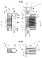
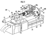
次に、図10乃至図12を参照して、本発明の脚式移動ロボットの充電システムの第2実施形態について説明する。図10は第2実施形態におけるロボットのリアカバー内に設けられた受電コネクタ等の構成を示す説明図である。図11は第2実施形態における充電ステーションの主要な内部構造を示す説明図である。図12は第2実施形態における受電コネクタと給電コネクタとの接続状態を示す説明図である。この第2実施形態の説明において、上記実施形態と同一の構成には同一の符号を付すことにより詳細な説明は省略する。また、図10ではロボット1’のリアカバー3ではシャッタ部の図示を省略している。
Next, a second embodiment of the charging system for the legged mobile robot of the present invention will be described with reference to FIGS. FIG. 10 is an explanatory diagram illustrating a configuration of a power receiving connector or the like provided in the rear cover of the robot according to the second embodiment. FIG. 11 is an explanatory diagram showing the main internal structure of the charging station in the second embodiment. FIG. 12 is an explanatory diagram showing a connection state between the power receiving connector and the power feeding connector in the second embodiment. In the description of the second embodiment, the same components as those in the above embodiment are denoted by the same reference numerals, and detailed description thereof is omitted. In FIG. 10, the shutter portion is not shown in the
この第2実施形態の充電システムは、脚式移動ロボット1’に備えられたバッテリ2(図1参照)を充電ステーション20’において充電するシステムであり、図10に示す受電コネクタ4と、図11に示す給電コネクタ22と、図4に示す回路構成(嵌合ラッチ8に関する部分を除く)は、上記実施形態と同様の構成を備えている。一方、第2実施形態の充電システムと前記実施形態とは、主にガイド手段と、ロック機構と、移動手段の構成が異なっている。
The charging system according to the second embodiment is a system for charging a battery 2 (see FIG. 1) provided in a legged
第2実施形態におけるガイド手段は、ロボット1’側に設けられた一対のガイドスリーブ50と、充電ステーション20’側に設けられた一対のガイドピン60(60a,60b)とから構成される。ガイドスリーブ50は、図10に示すように、金属製の円筒体で構成されており、その開口端は外周方向に拡径されている。このガイドスリーブ50は、ロボット1’側に設けられた受電コネクタ4の左右両側部に設けられている。ガイドピン60a,60bは、図11に示すように、金属製の円柱体で構成されており、その先端部は円錐形状となってる。このガイドピン60a,60bは、充電ステーション20’側に設けられた給電コネクタ22の左右両側部に設けられている。
The guide means in the second embodiment includes a pair of
第2実施形態におけるロック機構は、ガイドスリーブ50に設けられたガイド溝51と、ガイドピン60の外周部に設けられ前記ガイド溝51内を移動可能な係止ピン61(係止突起)と、一対のガイドピン60a,60bのうちの一方のガイドピン60aを回動させるガイドピンモータ62(回動手段)と、このガイドピンモータ62に連結されて他方のガイドピン60bを回動させるリンク機構63とから構成される。ガイド溝51は、ガイドスリーブ50の開口端に向けて軸方向に延びる縦溝51aと、縦溝51aの奥側から周方向に延びる係止溝51bとからなる。このガイド溝51は、ガイドスリーブ50の左右両側壁に一対設けられている。また、一対のガイド溝51の係止溝51bが延びている方向は、共に開口端から見て同一方向(この第2実施形態では時計回り)となっている。係止ピン61は、金属製で円柱状であり、ガイドピン60を貫通してガイドピン60に固定されている。
The locking mechanism in the second embodiment includes a
ガイドピンモータ62は、一方のガイドピン60aの根元側に配置され、給電コネクタ22及びガイドピン60a,60bを保持するコネクタホルダ64に固定されている。また、リンク機構63は、ガイドピンモータ62の回動部分と他方のガイドピン60bとを連結し、他方のガイドピン60bを一方のガイドピン60aと同様に回動させる部材である。また、コネクタホルダ64のロボット1’に対向する表面には、ロボット1’の位置を検知する位置センサ65が設けられている。この位置センサ65は、ガイドピン60がガイドスリーブ50に挿入され、係止ピン61がガイド溝51の縦溝51aの奥側に到達したことを、ロボット1’のリアカバー3’と位置センサ65との距離により検知するものである。
The
また、第2実施形態における移動手段は、図11に示す第1ラバーフローティング66と、第2ラバーフローティング67(フローティング部)とから構成される。第1ラバーフローティング66は筒状に形成され、内部にコイルスプリング66aを一体成形したものとなっている。この構成により、第1ラバーフローティング66の軸方向の長さは、所定量(第2実施形態では約25mm)伸縮自在となっている。また、この第1ラバーフローティング66は、図11に示すように、コネクタホルダ64の後端部と後述する支持ロッド68とを連結している。
In addition, the moving means in the second embodiment includes a first rubber floating 66 and a second rubber floating 67 (floating part) shown in FIG. The first rubber floating 66 is formed in a cylindrical shape, and a coil spring 66a is integrally formed therein. With this configuration, the length of the first rubber floating 66 in the axial direction can be expanded and contracted by a predetermined amount (about 25 mm in the second embodiment). Further, as shown in FIG. 11, the first rubber floating 66 connects the rear end portion of the
支持ロッド68は、図11に示すように円柱棒状の部材であり、支点ホルダ69、第2ラバーフローティング67及びフローティングホルダ70によって充電ステーション20’の内部に保持されている。また、支持ロッド68は、コネクタホルダ64と支点ホルダ69との間の部分が2重管構造となっており、コネクタホルダ64と支点ホルダ69との間の距離は変更可能となっている。また、コネクタホルダ64と支持ロッド68とは、第1ラバーフローティング66によって互いに連結されているため、コネクタホルダ64と支点ホルダ69との距離は約25mm変更自在となっている。
The
第2ラバーフローティング67は、中心に支持ロッド68が貫通する円柱状の部材であり、その外周面はフローティングホルダ70に支持されている。支持ロッド68がこの第2ラバーフローティング67により支持されることにより、支持ロッド68が第2ラバーフローティング67の弾性によって径方向に所定量(第2実施形態では約4mm)移動可能となっている。また、第2ラバーフローティング67の後方の支持ロッド68にはバランスウエイト71が設けられている。
The second rubber floating 67 is a cylindrical member through which the
また、支点ホルダ69及びフローティングホルダ70は、図11に示すように、共に充電ステーション20’内の支持プレート72に固定されている。この支持プレート72は、軸方向アクチュエータ73によって支持ロッド68の軸方向に移動自在となっている。
Further, as shown in FIG. 11, the
次に、第2実施形態の充電システムにおけるガイド手段、ロック機構及び移動手段の作動について説明する。ロボット1’が充電を行うときは、図5に示すS1からS4と同様の処理を行って充電ステーション20’の所定位置に移動させる。そして、図5に示すS5と同様に、ロボット1’は後方に重心を移すことにより腰位置を移動させ、受電コネクタ4を給電コネクタ22に近づける。
Next, the operation of the guide means, the lock mechanism, and the moving means in the charging system of the second embodiment will be described. When the
このとき、図12に示すように、受電コネクタ4と給電コネクタ22との位置が若干ずれている場合であっても、ガイドピン60の先端形状が円錐形であり、ガイドスリーブ50の開口端形状が外周方向に拡径するものであるため、ガイドピン60がガイドスリーブ50の内周面に沿ってガイドスリーブ50の奥側に挿入される。このとき、ガイドピン60はコネクタホルダ64に固定され、コネクタホルダ64は支持ロッド68に接続され、支持ロッド68は支点ホルダ69を介して揺動自在に充電ステーション20’に支持されており、支持ロッド68は第2ラバーフローティング67によって所定量径方向に移動自在に係止されているので、ガイドピン60は径方向に所定量移動可能となっている。
At this time, as shown in FIG. 12, even if the positions of the
また、ロボット1’が充電ステーション20’にもたれかかる際に、第1ラバーフローティング66によってロボット1’の移動方向の荷重を受けるため、何らかの原因によりロボット1’が急激にもたれかかった場合であっても、第1ラバーフローティング66の弾性によってその衝撃が緩和される。従って、第2実施形態の充電システムでは、常に給電コネクタ22と受電コネクタ4との接続が円滑に行われる。
Further, when the
また、ガイドピン60の係止ピン61がガイドスリーブ50のガイド溝51の縦溝51aに沿って案内され、縦溝51aの奥側に挿入されたときは、位置センサ65が作動してガイドピン60の係止ピン61が縦溝51aの奥側に到達したことがコントローラ30に検知される。このとき、コントローラ30は、ガイドピンモータ62によってガイドピン60aを回動させると共にリンク機構63によって他方のガイドピン60bを回動させ、係止ピン61をガイド溝51の係止溝51bに進入させる。そして、コントローラ30は、この状態でガイドピン60a,60bの動きを停止させる。
Further, when the locking
以上の作動により、受電コネクタ4と給電コネクタ22とが確実に接続される。そして、コントローラ30は、図4のS6と同様に受電端子7と給電端子29との接続が確認された後、ロボット1’のバッテリ2への充電を開始する。このとき、ロボット1’に何らかの要因で外部から力が加わった場合であっても、ガイドピン60とガイドスリーブ50とが係止ピン61及び係止溝51bによって係止されているので、充電中に両コネクタが外れることはない。
With the above operation, the
次に、第2実施形態の充電システムにおいて、ロボット1’が充電ステーション20’を離脱する際の作動について説明する。この第2実施形態のいても、給電コネクタ22から受電コネクタ4を離脱させるに先立って、充電用電源26からバッテリ2に供給されていた充電用電流を遮断する(図9のS21参照)。次に、コントローラ30はガイドピンモータ62を接続時とは逆方向に回動させ、ガイドピン60の係止ピン61をガイドスリーブ50に設けられたガイド溝51の係止溝51bから縦溝51aに移動させる。
Next, an operation when the robot 1 'leaves the charging station 20' in the charging system of the second embodiment will be described. Even in the second embodiment, the charging current supplied from the charging
コントローラ30は、ガイドピン60を回動させてガイドピン60とガイドスリーブ50との係止を解除した後、ロボット1’の腰を充電を行う前の位置に戻すようにロボット1’の制御を行う(図9のS25参照)。当該操作により、受電コネクタ4と給電コネクタ22との接続が解除される。その他の制御については、図9のS23とS24を除いて図9の各ステップと同様の制御が行われる。
The
以上のように、第2実施形態においては、ガイドピン60とガイドスリーブ50によってガイド手段及びロック機構が構成され、第1ラバーフローティング66及び第2ラバーフローティング67によって移動手段が構成されているため、充電システム全体の構成をコンパクトなものとすることができる。特に、上記実施形態の充電ステーション20のスライド機構23に代えて、ロボット1’の移動方向に延びるガイドピン60を設けたので、充電ステーション20’は、その幅方向がコンパクトなものとなり、充電ステーション20’を設置するためのレイアウト自由度が向上する。
As described above, in the second embodiment, the guide means 60 and the locking mechanism are configured by the guide pin 60 and the
また、第2実施形態においては、図11に示す軸方向アクチュエータ73によって支持プレート72が支持ロッド68の軸方向に移動自在となっている。従って、例えば、ロボット1’の充電時の位置合わせに誤差が生じ、受電コネクタ4と給電コネクタ22との距離が離れていることが位置センサ65によって検知された場合であっても、軸方向アクチュエータ73により各コネクタの位置の調整を行うことができる。また、軸方向アクチュエータ73により、ロボット1’が充電のために充電ステーション20’に近づいてきたときだけ給電コネクタ22及びガイドピン60を充電ステーション20’の外部に露出させ、ロボット1’の充電を行わないときには、給電コネクタ22及びガイドピン60を充電ステーション20’の内部に格納しておくことも可能となる。また、ロボット1’の充電時に、ロボット1’を充電ステーション20’に寄りかからせないで、軸方向アクチュエータ73により給電コネクタ22を受電コネクタ4側に移動させ、ロボット1’が直立の状態で充電を行うことも可能となる。
In the second embodiment, the
なお、第2実施形態においては、受電コネクタ4側にガイドスリーブ50を設け、給電コネクタ22側にガイドピン60を設けているが、これに限らず、受電コネクタ4側にガイドピン60を設け、給電コネクタ22側にガイドスリーブ50を設けてもよい。また、第2実施形態においては、ロック機構をガイドピン60に設けられた係止ピン61と、ガイドスリーブ50に設けられたガイド溝51によって形成しているが、上記実施形態と同様に嵌合ラッチ8を用いてもよい。
In the second embodiment, the
また、第2実施形態においては、移動手段を第1ラバーフローティング66と第2ラバーフローティング67とで構成しているが、給電コネクタ22及びガイドピン60が、ガイドピン60の径方向に移動可能であれば、どちらか一方のラバーフローティングのみでもよい。
In the second embodiment, the moving means includes the first rubber floating 66 and the second rubber floating 67. However, the
1…脚式移動ロボット、2…バッテリ、4…受電コネクタ、7…受電端子、
20…充電ステーション、21…ホルダ(ガイド手段)、22…給電コネクタ、23…スライド機構(移動手段)、26…充電用電源、29…給電端子。
1 ... legged mobile robot, 2 ... battery, 4 ... power receiving connector, 7 ... power receiving terminal,
DESCRIPTION OF
Claims (9)
前記ロボットが充電を行う充電ステーションを備え、
前記ロボットは受電端子が設けられた受電コネクタを有し、
前記充電ステーションは、前記バッテリに対して充電電流を出力する充電用電源と、前記受電コネクタに接続される給電コネクタと、前記給電コネクタに設けられ前記受電端子に接触する給電端子と、前記ロボットが充電を行うために接近した際に前記ロボットが接近するに従って前記受電コネクタと前記給電コネクタとの所定方向の相対的なずれを縮小させるように案内するガイド手段と、前記ロボットの接近に伴って前記ガイド手段に生じる力によって前記ガイド手段を前記所定方向に移動させる移動手段とを有していることを特徴とする脚式移動ロボットの充電システム。 A charging system for charging a battery provided in a legged mobile robot,
A charging station for charging the robot;
The robot has a power receiving connector provided with a power receiving terminal,
The charging station includes a charging power source that outputs a charging current to the battery, a power feeding connector connected to the power receiving connector, a power feeding terminal provided in the power feeding connector and in contact with the power receiving terminal, and the robot Guide means for guiding the robot to reduce a relative displacement in a predetermined direction between the power receiving connector and the power feeding connector as the robot approaches when approaching to perform charging, and as the robot approaches, the guide means A charging system for a legged mobile robot, comprising: moving means for moving the guide means in the predetermined direction by a force generated in the guide means.
前記移動手段は、弾性により前記ガイドピン又は前記ガイドスリーブを前記所定方向に移動可能とするフローティング部であることを特徴とする請求項1に記載の脚式移動ロボットの充電システム。 The guide means includes a guide pin having a tapered tip provided at one of the robot and the charging station, and an opening provided at the other of the robot or the charging station and into which the guide pin is inserted. It consists of an enlarged guide sleeve,
2. The charging system for a legged mobile robot according to claim 1, wherein the moving unit is a floating portion that allows the guide pin or the guide sleeve to move in the predetermined direction by elasticity. 3.
前記接続検知手段により前記受電端子と前記給電端子とが接続状態にあることが検知されたときに、前記給電端子及び前記受電端子を介して、前記充電用電源から前記バッテリに充電電流を供給して前記バッテリを充電する充電制御手段とを備えていることを特徴とする請求項1乃至7のいずれか1項に記載の脚式移動ロボットの充電システム。 The charging station includes connection detection means for detecting whether the power receiving terminal and the power feeding terminal are in a connected state;
When the connection detecting means detects that the power receiving terminal and the power feeding terminal are in a connected state, a charging current is supplied from the charging power source to the battery via the power feeding terminal and the power receiving terminal. The charging system for a legged mobile robot according to any one of claims 1 to 7, further comprising charging control means for charging the battery.
Priority Applications (3)
| Application Number | Priority Date | Filing Date | Title |
|---|---|---|---|
| JP2007033344A JP2007245332A (en) | 2006-02-14 | 2007-02-14 | Charging system of legged mobile robot |
| EP07003132.3A EP1819026A3 (en) | 2006-02-14 | 2007-02-14 | Charging system for legged mobile robot |
| US11/705,772 US7719229B2 (en) | 2006-02-14 | 2007-02-14 | Charging system for legged mobile robot |
Applications Claiming Priority (2)
| Application Number | Priority Date | Filing Date | Title |
|---|---|---|---|
| JP2006037151 | 2006-02-14 | ||
| JP2007033344A JP2007245332A (en) | 2006-02-14 | 2007-02-14 | Charging system of legged mobile robot |
Publications (1)
| Publication Number | Publication Date |
|---|---|
| JP2007245332A true JP2007245332A (en) | 2007-09-27 |
Family
ID=38179784
Family Applications (1)
| Application Number | Title | Priority Date | Filing Date |
|---|---|---|---|
| JP2007033344A Pending JP2007245332A (en) | 2006-02-14 | 2007-02-14 | Charging system of legged mobile robot |
Country Status (3)
| Country | Link |
|---|---|
| US (1) | US7719229B2 (en) |
| EP (1) | EP1819026A3 (en) |
| JP (1) | JP2007245332A (en) |
Cited By (16)
| Publication number | Priority date | Publication date | Assignee | Title |
|---|---|---|---|---|
| JP2009113181A (en) * | 2007-11-09 | 2009-05-28 | Honda Motor Co Ltd | Charging system for walking robot and charging method therefor |
| EP2072385A1 (en) | 2007-12-10 | 2009-06-24 | Honda Motor Co., Ltd. | Robot |
| WO2009090864A1 (en) * | 2008-01-15 | 2009-07-23 | Honda Motor Co., Ltd. | Robot |
| EP2426154A1 (en) | 2007-09-21 | 2012-03-07 | Fujifilm Corporation | Photosensitive composition, pattern forming method using the photosensitive composition and compound for use in the photosensitive composition |
| JP2013542704A (en) * | 2010-10-28 | 2013-11-21 | ローベルト ボツシユ ゲゼルシヤフト ミツト ベシユレンクテル ハフツング | Charging method for hybrid vehicle or electric vehicle |
| JP2014008563A (en) * | 2012-06-28 | 2014-01-20 | Honda Motor Co Ltd | Control device of mobile robot |
| WO2014081141A1 (en) * | 2012-11-21 | 2014-05-30 | Samsung Techwin Co., Ltd | Docking module, mobile robot comprising docking module, docking system comprising mobile robot, and method of docking mobile robot |
| KR101469204B1 (en) * | 2014-02-06 | 2014-12-09 | 한국기계연구원 | Worktable fixation device for robot |
| KR101469203B1 (en) * | 2014-02-06 | 2014-12-09 | 한국기계연구원 | Worktable fixation device for robot |
| JP2019511895A (en) * | 2016-04-01 | 2019-04-25 | ローカス ロボティクス コーポレーションLocus Robotics Corp. | Robot charging system |
| WO2019082779A1 (en) * | 2017-10-23 | 2019-05-02 | Groove X株式会社 | Robot charging station |
| JP2020036412A (en) * | 2018-08-28 | 2020-03-05 | 矢崎総業株式会社 | Vehicle charging system |
| JP2021083148A (en) * | 2019-11-14 | 2021-05-27 | 三菱電機特機システム株式会社 | Power supply device |
| JP2021097452A (en) * | 2019-12-13 | 2021-06-24 | 株式会社日立ビルシステム | Charging device |
| JP2022032202A (en) * | 2020-08-11 | 2022-02-25 | 株式会社日立ビルシステム | Charging system of mobile object |
| JP7327131B2 (en) | 2019-12-05 | 2023-08-16 | オムロン株式会社 | charging unit |
Families Citing this family (83)
| Publication number | Priority date | Publication date | Assignee | Title |
|---|---|---|---|---|
| US20040162637A1 (en) | 2002-07-25 | 2004-08-19 | Yulun Wang | Medical tele-robotic system with a master remote station with an arbitrator |
| US6925357B2 (en) | 2002-07-25 | 2005-08-02 | Intouch Health, Inc. | Medical tele-robotic system |
| US7813836B2 (en) | 2003-12-09 | 2010-10-12 | Intouch Technologies, Inc. | Protocol for a remotely controlled videoconferencing robot |
| US20050204438A1 (en) | 2004-02-26 | 2005-09-15 | Yulun Wang | Graphical interface for a remote presence system |
| US8077963B2 (en) | 2004-07-13 | 2011-12-13 | Yulun Wang | Mobile robot with a head-based movement mapping scheme |
| US9198728B2 (en) | 2005-09-30 | 2015-12-01 | Intouch Technologies, Inc. | Multi-camera mobile teleconferencing platform |
| US8849679B2 (en) | 2006-06-15 | 2014-09-30 | Intouch Technologies, Inc. | Remote controlled robot system that provides medical images |
| JP4893887B2 (en) | 2007-04-02 | 2012-03-07 | 本田技研工業株式会社 | Charger |
| US9160783B2 (en) | 2007-05-09 | 2015-10-13 | Intouch Technologies, Inc. | Robot system that operates through a network firewall |
| TWI315705B (en) | 2007-12-28 | 2009-10-11 | Ind Tech Res Inst | Workstation |
| US10875182B2 (en) | 2008-03-20 | 2020-12-29 | Teladoc Health, Inc. | Remote presence system mounted to operating room hardware |
| US8179418B2 (en) | 2008-04-14 | 2012-05-15 | Intouch Technologies, Inc. | Robotic based health care system |
| US8170241B2 (en) | 2008-04-17 | 2012-05-01 | Intouch Technologies, Inc. | Mobile tele-presence system with a microphone system |
| CN101607399A (en) * | 2008-06-19 | 2009-12-23 | 鸿富锦精密工业(深圳)有限公司 | Charging device |
| US9193065B2 (en) * | 2008-07-10 | 2015-11-24 | Intouch Technologies, Inc. | Docking system for a tele-presence robot |
| US9842192B2 (en) | 2008-07-11 | 2017-12-12 | Intouch Technologies, Inc. | Tele-presence robot system with multi-cast features |
| US8340819B2 (en) | 2008-09-18 | 2012-12-25 | Intouch Technologies, Inc. | Mobile videoconferencing robot system with network adaptive driving |
| US8996165B2 (en) | 2008-10-21 | 2015-03-31 | Intouch Technologies, Inc. | Telepresence robot with a camera boom |
| US9138891B2 (en) | 2008-11-25 | 2015-09-22 | Intouch Technologies, Inc. | Server connectivity control for tele-presence robot |
| US8463435B2 (en) | 2008-11-25 | 2013-06-11 | Intouch Technologies, Inc. | Server connectivity control for tele-presence robot |
| US8849680B2 (en) | 2009-01-29 | 2014-09-30 | Intouch Technologies, Inc. | Documentation through a remote presence robot |
| US8897920B2 (en) | 2009-04-17 | 2014-11-25 | Intouch Technologies, Inc. | Tele-presence robot system with software modularity, projector and laser pointer |
| US8384755B2 (en) | 2009-08-26 | 2013-02-26 | Intouch Technologies, Inc. | Portable remote presence robot |
| US11399153B2 (en) | 2009-08-26 | 2022-07-26 | Teladoc Health, Inc. | Portable telepresence apparatus |
| TWM377001U (en) * | 2009-10-16 | 2010-03-21 | Micro Star Int Co Ltd | Electronic device |
| US8212533B2 (en) * | 2009-12-23 | 2012-07-03 | Toyota Motor Engineering & Manufacturing North America, Inc. | Robot battery charging apparatuses and methods |
| US11154981B2 (en) | 2010-02-04 | 2021-10-26 | Teladoc Health, Inc. | Robot user interface for telepresence robot system |
| US8670017B2 (en) | 2010-03-04 | 2014-03-11 | Intouch Technologies, Inc. | Remote presence system including a cart that supports a robot face and an overhead camera |
| US10343283B2 (en) | 2010-05-24 | 2019-07-09 | Intouch Technologies, Inc. | Telepresence robot system that can be accessed by a cellular phone |
| US10808882B2 (en) | 2010-05-26 | 2020-10-20 | Intouch Technologies, Inc. | Tele-robotic system with a robot face placed on a chair |
| FR2962859B1 (en) * | 2010-07-15 | 2012-09-21 | Electro Alu | CONNECTION MODULE |
| JP2012034468A (en) * | 2010-07-29 | 2012-02-16 | Toyota Industries Corp | Resonance type non-contact power feeding system for vehicle |
| US20120091824A1 (en) * | 2010-10-19 | 2012-04-19 | Leviton Manufacturing Co., Inc. | Electric Vehicle Supply Equipment with Line Fitting Disconnect Sensing |
| CN102565754B (en) * | 2010-11-30 | 2014-02-26 | 华硕电脑股份有限公司 | Positioning method of movable apparatus and positioning system |
| US9264664B2 (en) | 2010-12-03 | 2016-02-16 | Intouch Technologies, Inc. | Systems and methods for dynamic bandwidth allocation |
| US20120191517A1 (en) | 2010-12-15 | 2012-07-26 | Daffin Jr Mack Paul | Prepaid virtual card |
| US8965579B2 (en) | 2011-01-28 | 2015-02-24 | Intouch Technologies | Interfacing with a mobile telepresence robot |
| US9323250B2 (en) | 2011-01-28 | 2016-04-26 | Intouch Technologies, Inc. | Time-dependent navigation of telepresence robots |
| US10769739B2 (en) | 2011-04-25 | 2020-09-08 | Intouch Technologies, Inc. | Systems and methods for management of information among medical providers and facilities |
| US9098611B2 (en) | 2012-11-26 | 2015-08-04 | Intouch Technologies, Inc. | Enhanced video interaction for a user interface of a telepresence network |
| US20140139616A1 (en) | 2012-01-27 | 2014-05-22 | Intouch Technologies, Inc. | Enhanced Diagnostics for a Telepresence Robot |
| US8836751B2 (en) | 2011-11-08 | 2014-09-16 | Intouch Technologies, Inc. | Tele-presence system with a user interface that displays different communication links |
| US8902278B2 (en) | 2012-04-11 | 2014-12-02 | Intouch Technologies, Inc. | Systems and methods for visualizing and managing telepresence devices in healthcare networks |
| US9251313B2 (en) | 2012-04-11 | 2016-02-02 | Intouch Technologies, Inc. | Systems and methods for visualizing and managing telepresence devices in healthcare networks |
| US9361021B2 (en) | 2012-05-22 | 2016-06-07 | Irobot Corporation | Graphical user interfaces including touchpad driving interfaces for telemedicine devices |
| WO2013176758A1 (en) | 2012-05-22 | 2013-11-28 | Intouch Technologies, Inc. | Clinical workflows utilizing autonomous and semi-autonomous telemedicine devices |
| US11565598B2 (en) * | 2013-03-15 | 2023-01-31 | Symbotic Llc | Rover charging system with one or more charging stations configured to control an output of the charging station independent of a charging station status |
| EP2978627B1 (en) * | 2013-03-27 | 2017-05-24 | ABB Schweiz AG | Drive inverter shared by different motors in a vehicle |
| TW201445278A (en) * | 2013-05-20 | 2014-12-01 | Hon Hai Prec Ind Co Ltd | Mobile power supply |
| HUE055848T2 (en) * | 2013-08-09 | 2021-12-28 | Schunk Transit Sys Gmbh | Rapid charging system and method for electrically connecting a vehicle to a charging station |
| USD762567S1 (en) * | 2013-10-11 | 2016-08-02 | Mimoco | USB battery charger |
| USD760649S1 (en) | 2015-06-22 | 2016-07-05 | Mtd Products Inc | Docking station |
| CN105048540B (en) * | 2015-07-08 | 2018-01-02 | 江苏大学 | A kind of charging device of greenhouse automatic detecting platform |
| FR3049359B1 (en) * | 2016-03-23 | 2020-01-10 | Aldebaran Robotics | METHOD FOR RECHARGING A BATTERY |
| WO2018027572A1 (en) * | 2016-08-09 | 2018-02-15 | 衣佳鑫 | Electric quantity control method and system for robot in internet of things |
| CN106254188A (en) * | 2016-08-09 | 2016-12-21 | 衣佳鑫 | Robot electric quantity control method and system in Internet of Things |
| WO2018064810A1 (en) * | 2016-10-08 | 2018-04-12 | 浙江国自机器人技术有限公司 | Mobile robot autonomous charging device |
| EP3392974A1 (en) | 2017-04-21 | 2018-10-24 | HILTI Aktiengesellschaft | Spring contacts for a battery |
| US11862302B2 (en) | 2017-04-24 | 2024-01-02 | Teladoc Health, Inc. | Automated transcription and documentation of tele-health encounters |
| CN107017676A (en) * | 2017-04-28 | 2017-08-04 | 浙江国自机器人技术有限公司 | A kind of mobile robot recharging device |
| US10483007B2 (en) | 2017-07-25 | 2019-11-19 | Intouch Technologies, Inc. | Modular telehealth cart with thermal imaging and touch screen user interface |
| CN107482718B (en) * | 2017-08-14 | 2023-07-14 | 深圳市优必选科技有限公司 | Charging base and robot |
| US11636944B2 (en) | 2017-08-25 | 2023-04-25 | Teladoc Health, Inc. | Connectivity infrastructure for a telehealth platform |
| CN107591857A (en) * | 2017-09-19 | 2018-01-16 | 上海悦合自动化技术有限公司 | The automatic charging equipment and its application method of mobile robot |
| US10243379B1 (en) * | 2017-09-22 | 2019-03-26 | Locus Robotics Corp. | Robot charging station protective member |
| CN107465277B (en) * | 2017-09-30 | 2024-02-09 | 深圳市锐曼智能装备有限公司 | Magnetic resonance type automatic charging robot and charging method thereof |
| CN107748203B (en) * | 2017-11-16 | 2024-01-26 | 西安石油大学 | Intelligent self-tracking weld joint flaw detection robot |
| CN109932844B (en) | 2017-12-15 | 2022-04-05 | 京东方科技集团股份有限公司 | Display panel and display device |
| CN107933367B (en) * | 2017-12-19 | 2023-09-26 | 库卡机器人(广东)有限公司 | Charging device for unmanned carrier and unmanned carrier with charging device |
| CN109976324B (en) * | 2017-12-27 | 2022-06-28 | 深圳市优必选科技有限公司 | Method for controlling robot charging, robot, and computer-readable storage medium |
| CN108199432A (en) * | 2018-01-08 | 2018-06-22 | 浙江立石机器人技术有限公司 | A kind of automatic charge device of mobile robot |
| US10617299B2 (en) | 2018-04-27 | 2020-04-14 | Intouch Technologies, Inc. | Telehealth cart that supports a removable tablet with seamless audio/video switching |
| JP2019197681A (en) * | 2018-05-10 | 2019-11-14 | シャープ株式会社 | Electronic apparatus, charging stand, and charging system |
| CN109100745B (en) * | 2018-08-22 | 2020-08-07 | 江苏省江都水利工程管理处 | Automatic system of patrolling and examining of water conservancy pump station |
| CN109512335B (en) * | 2018-11-28 | 2021-04-20 | 苏州凯丽达电器有限公司 | Dust collector charging terminal seat with adjustable charging terminal position |
| US11552488B2 (en) * | 2019-06-07 | 2023-01-10 | Te Connectivity Solutions Gmbh | Charging system for a mobile device |
| CN110198069A (en) * | 2019-07-04 | 2019-09-03 | 科大智能机器人技术有限公司 | A kind of charging electrode device of crusing robot |
| KR20210048063A (en) * | 2019-10-23 | 2021-05-03 | 엘지전자 주식회사 | Charging station |
| CN110994710B (en) * | 2019-11-08 | 2023-02-24 | 合肥科大智能机器人技术有限公司 | Self-adaptive self-charging mechanism |
| CN110957776B (en) * | 2019-11-15 | 2021-12-31 | 深圳市优必选科技股份有限公司 | Power supply structure, charging adjusting device and robot charging system |
| US20220194245A1 (en) * | 2020-12-22 | 2022-06-23 | Boston Dynamics, Inc. | Robust Docking of Robots with Imperfect Sensing |
| CN113852156B (en) * | 2021-09-15 | 2023-08-25 | 珠海格力电器股份有限公司 | Charging device, charging method, charging device, and computer-readable storage medium |
| CN116388342B (en) * | 2023-05-23 | 2023-10-27 | 江苏三里盛鑫工程技术有限公司 | Service type robot charging device |
Citations (5)
| Publication number | Priority date | Publication date | Assignee | Title |
|---|---|---|---|---|
| JPS6339776A (en) * | 1986-08-05 | 1988-02-20 | 工業技術院長 | Feed facility for independent travelling type robot |
| JPH07275171A (en) * | 1994-03-31 | 1995-10-24 | Samsung Electron Co Ltd | Power supply device of automatic vacuum cleaner |
| JPH0837705A (en) * | 1994-07-26 | 1996-02-06 | Toyota Motor Corp | Electrically driven moving body and charger therefor |
| JP2001079792A (en) * | 1999-09-09 | 2001-03-27 | Denso Corp | Charging electrode structure of mobile robot |
| JP2001179663A (en) * | 1999-12-24 | 2001-07-03 | Sony Corp | Leg type mobile robot, its control method and charging station |
Family Cites Families (4)
| Publication number | Priority date | Publication date | Assignee | Title |
|---|---|---|---|---|
| FR2736757B1 (en) * | 1995-07-11 | 1997-08-22 | Carrier Kheops Bac | ELECTRICAL CONNECTOR WITH AUTOMATIC PLUG |
| JP4207336B2 (en) * | 1999-10-29 | 2009-01-14 | ソニー株式会社 | Charging system for mobile robot, method for searching for charging station, mobile robot, connector, and electrical connection structure |
| DE10258106A1 (en) * | 2002-12-11 | 2004-06-24 | Volkswagen Ag | Electric plug-in connection for sliding door on road vehicle has plug and/or bushing displaceably mounted in relation to respective housing |
| JP4023355B2 (en) * | 2003-03-31 | 2007-12-19 | トヨタ自動車株式会社 | Walking robot |
-
2007
- 2007-02-14 US US11/705,772 patent/US7719229B2/en not_active Expired - Fee Related
- 2007-02-14 JP JP2007033344A patent/JP2007245332A/en active Pending
- 2007-02-14 EP EP07003132.3A patent/EP1819026A3/en not_active Withdrawn
Patent Citations (5)
| Publication number | Priority date | Publication date | Assignee | Title |
|---|---|---|---|---|
| JPS6339776A (en) * | 1986-08-05 | 1988-02-20 | 工業技術院長 | Feed facility for independent travelling type robot |
| JPH07275171A (en) * | 1994-03-31 | 1995-10-24 | Samsung Electron Co Ltd | Power supply device of automatic vacuum cleaner |
| JPH0837705A (en) * | 1994-07-26 | 1996-02-06 | Toyota Motor Corp | Electrically driven moving body and charger therefor |
| JP2001079792A (en) * | 1999-09-09 | 2001-03-27 | Denso Corp | Charging electrode structure of mobile robot |
| JP2001179663A (en) * | 1999-12-24 | 2001-07-03 | Sony Corp | Leg type mobile robot, its control method and charging station |
Cited By (27)
| Publication number | Priority date | Publication date | Assignee | Title |
|---|---|---|---|---|
| EP2426154A1 (en) | 2007-09-21 | 2012-03-07 | Fujifilm Corporation | Photosensitive composition, pattern forming method using the photosensitive composition and compound for use in the photosensitive composition |
| JP2009113181A (en) * | 2007-11-09 | 2009-05-28 | Honda Motor Co Ltd | Charging system for walking robot and charging method therefor |
| US8098042B2 (en) | 2007-11-09 | 2012-01-17 | Honda Motor Co., Ltd. | Charging system for walking robot and charging method therefor |
| EP2072385A1 (en) | 2007-12-10 | 2009-06-24 | Honda Motor Co., Ltd. | Robot |
| JP2009136997A (en) * | 2007-12-10 | 2009-06-25 | Honda Motor Co Ltd | Robot |
| JP4552037B2 (en) * | 2007-12-10 | 2010-09-29 | 本田技研工業株式会社 | robot |
| WO2009090864A1 (en) * | 2008-01-15 | 2009-07-23 | Honda Motor Co., Ltd. | Robot |
| JP2009166162A (en) * | 2008-01-15 | 2009-07-30 | Honda Motor Co Ltd | Robot |
| US8380348B2 (en) | 2008-01-15 | 2013-02-19 | Honda Motor Co., Ltd. | Robot |
| JP2013542704A (en) * | 2010-10-28 | 2013-11-21 | ローベルト ボツシユ ゲゼルシヤフト ミツト ベシユレンクテル ハフツング | Charging method for hybrid vehicle or electric vehicle |
| JP2014008563A (en) * | 2012-06-28 | 2014-01-20 | Honda Motor Co Ltd | Control device of mobile robot |
| WO2014081141A1 (en) * | 2012-11-21 | 2014-05-30 | Samsung Techwin Co., Ltd | Docking module, mobile robot comprising docking module, docking system comprising mobile robot, and method of docking mobile robot |
| KR101469204B1 (en) * | 2014-02-06 | 2014-12-09 | 한국기계연구원 | Worktable fixation device for robot |
| KR101469203B1 (en) * | 2014-02-06 | 2014-12-09 | 한국기계연구원 | Worktable fixation device for robot |
| JP2019511895A (en) * | 2016-04-01 | 2019-04-25 | ローカス ロボティクス コーポレーションLocus Robotics Corp. | Robot charging system |
| US10906419B2 (en) | 2016-04-01 | 2021-02-02 | Locus Robotics Corp. | Electrical charging system for a robot |
| WO2019082779A1 (en) * | 2017-10-23 | 2019-05-02 | Groove X株式会社 | Robot charging station |
| JP7137851B2 (en) | 2017-10-23 | 2022-09-15 | Groove X株式会社 | Robot charging station |
| JPWO2019082779A1 (en) * | 2017-10-23 | 2020-11-19 | Groove X株式会社 | Robot charging station |
| JP7094628B2 (en) | 2018-08-28 | 2022-07-04 | 矢崎総業株式会社 | Vehicle charging system |
| JP2020036412A (en) * | 2018-08-28 | 2020-03-05 | 矢崎総業株式会社 | Vehicle charging system |
| JP2021083148A (en) * | 2019-11-14 | 2021-05-27 | 三菱電機特機システム株式会社 | Power supply device |
| JP7296857B2 (en) | 2019-11-14 | 2023-06-23 | 三菱電機特機システム株式会社 | power supply |
| JP7327131B2 (en) | 2019-12-05 | 2023-08-16 | オムロン株式会社 | charging unit |
| JP2021097452A (en) * | 2019-12-13 | 2021-06-24 | 株式会社日立ビルシステム | Charging device |
| JP2022032202A (en) * | 2020-08-11 | 2022-02-25 | 株式会社日立ビルシステム | Charging system of mobile object |
| JP7339218B2 (en) | 2020-08-11 | 2023-09-05 | 株式会社日立ビルシステム | Mobile charging system |
Also Published As
| Publication number | Publication date |
|---|---|
| US20070216347A1 (en) | 2007-09-20 |
| US7719229B2 (en) | 2010-05-18 |
| EP1819026A2 (en) | 2007-08-15 |
| EP1819026A3 (en) | 2017-08-30 |
Similar Documents
| Publication | Publication Date | Title |
|---|---|---|
| JP2007245332A (en) | Charging system of legged mobile robot | |
| JP4893887B2 (en) | Charger | |
| KR101146907B1 (en) | Charging system for mobile robot | |
| JP4882114B2 (en) | Charging device and charging method for walking robot | |
| JP4252721B2 (en) | Biped robot | |
| JP4418381B2 (en) | Charging station for autonomous mobile robot | |
| JP7342618B2 (en) | Robot system and robot system control method | |
| JP6087498B2 (en) | Self-propelled device charging system | |
| US10579064B2 (en) | Autonomous robot charging profile selection | |
| JP2010012529A (en) | Robot | |
| TW201517402A (en) | Connector device | |
| CN107396680B (en) | Automatic working system, charging station and method for returning intelligent mower to charging station | |
| JP2008043035A (en) | Self-traveling robot | |
| JP2008099425A (en) | Power supply device | |
| JP2010057887A (en) | Carriage for image diagnostic apparatus | |
| JP2007152472A (en) | Charging system, charging station and robot guidance system | |
| JP2008129696A (en) | Mobile robot, mobile robot charging system, and mobile robot charging method | |
| JP4485887B2 (en) | Force sensor abnormality detection device for legged mobile robot | |
| CN106068583B (en) | Lever-fitting type connector | |
| EP2343160B1 (en) | Electric power tool | |
| JP2021079090A (en) | Feeding device for feeding travelable equipment with material, and travelable equipment | |
| US20230264588A1 (en) | Charging of batteries for mobile robots | |
| JP2017121199A (en) | Agricultural machine and remote controller of the same | |
| EP2796353B1 (en) | Saddle-type electric vehicle | |
| JP6513973B2 (en) | Electrode unit and traveling apparatus |
Legal Events
| Date | Code | Title | Description |
|---|---|---|---|
| A621 | Written request for application examination |
Free format text: JAPANESE INTERMEDIATE CODE: A621 Effective date: 20091126 |
|
| A131 | Notification of reasons for refusal |
Free format text: JAPANESE INTERMEDIATE CODE: A131 Effective date: 20110222 |
|
| A977 | Report on retrieval |
Free format text: JAPANESE INTERMEDIATE CODE: A971007 Effective date: 20110224 |
|
| A02 | Decision of refusal |
Free format text: JAPANESE INTERMEDIATE CODE: A02 Effective date: 20110927 |